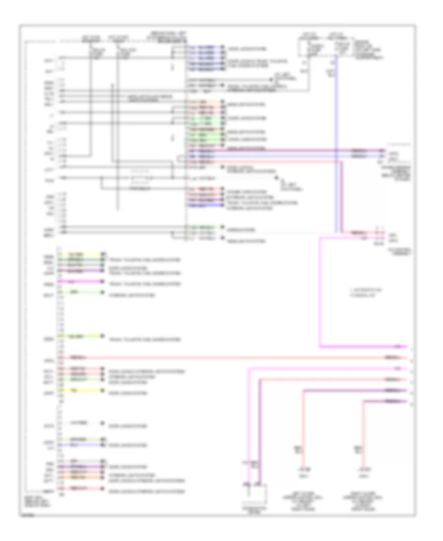
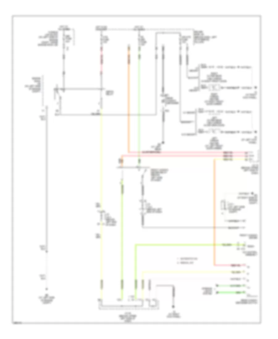
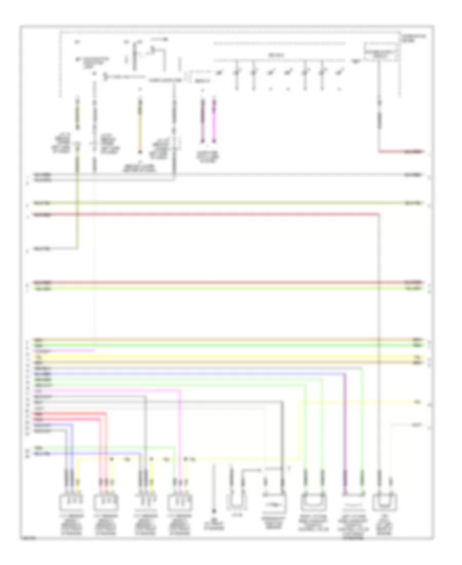
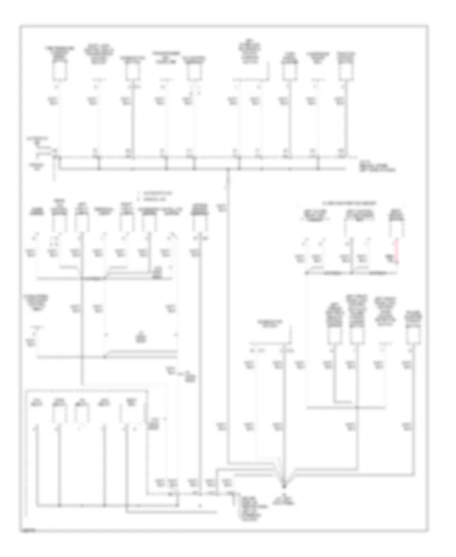
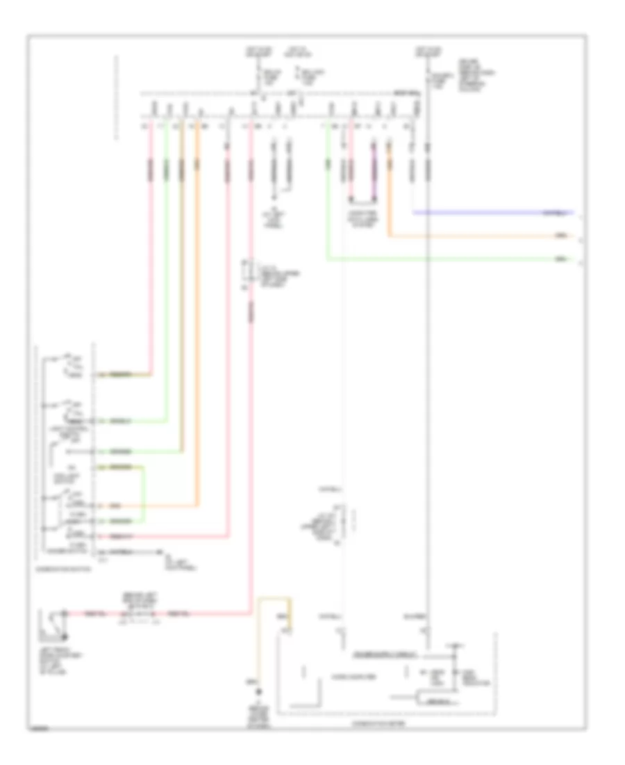
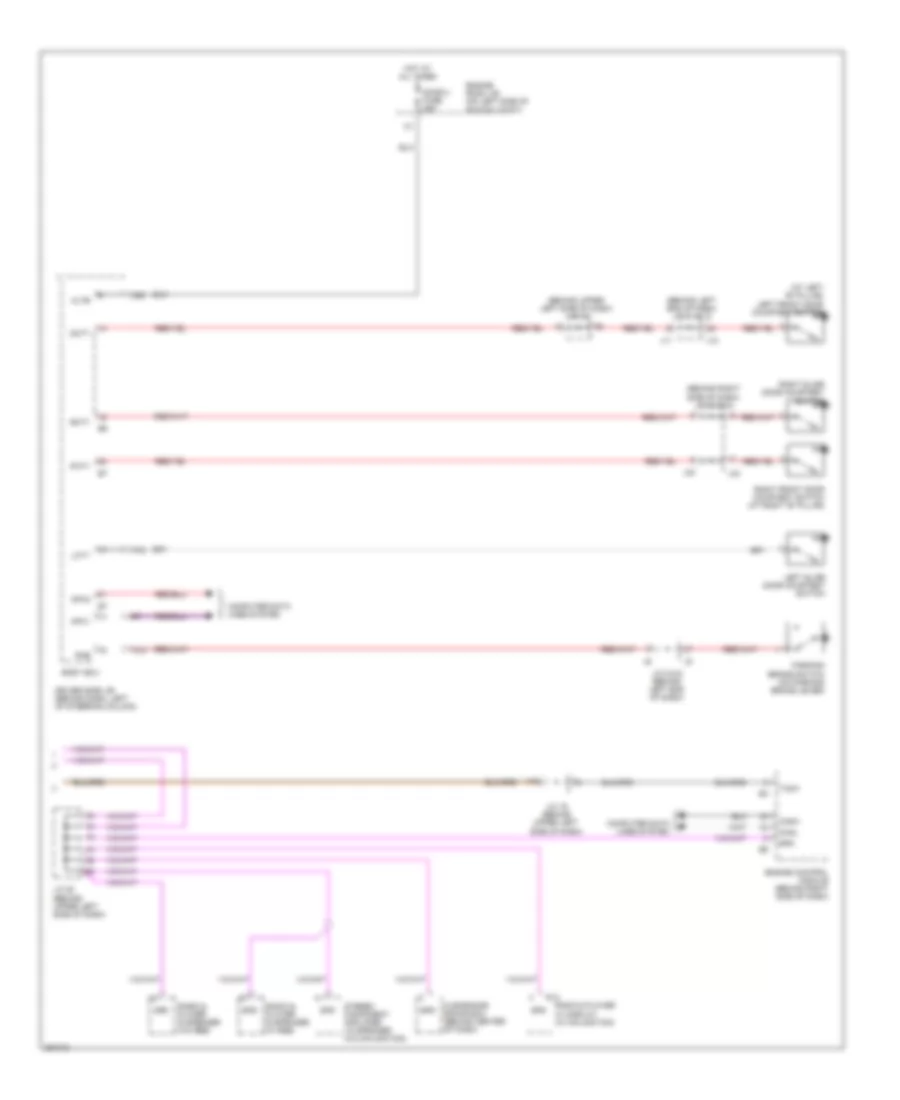
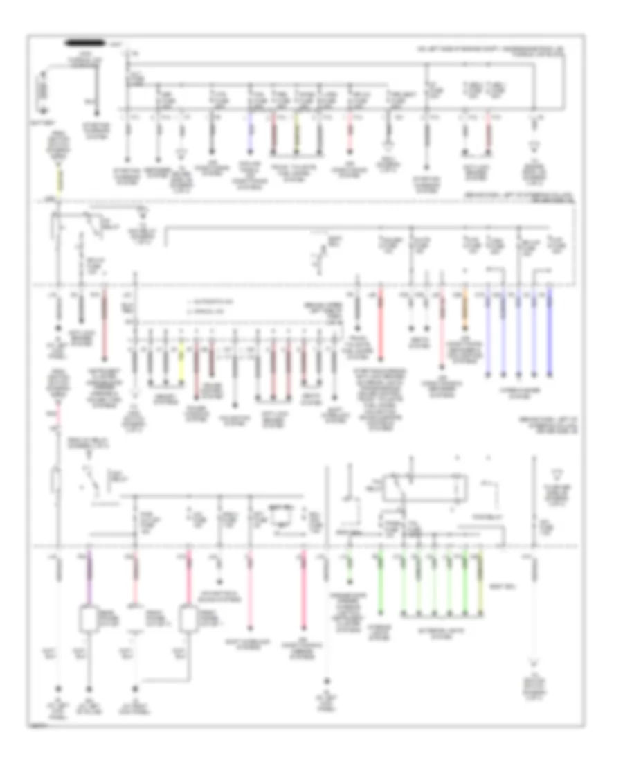
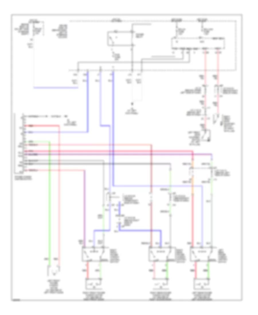
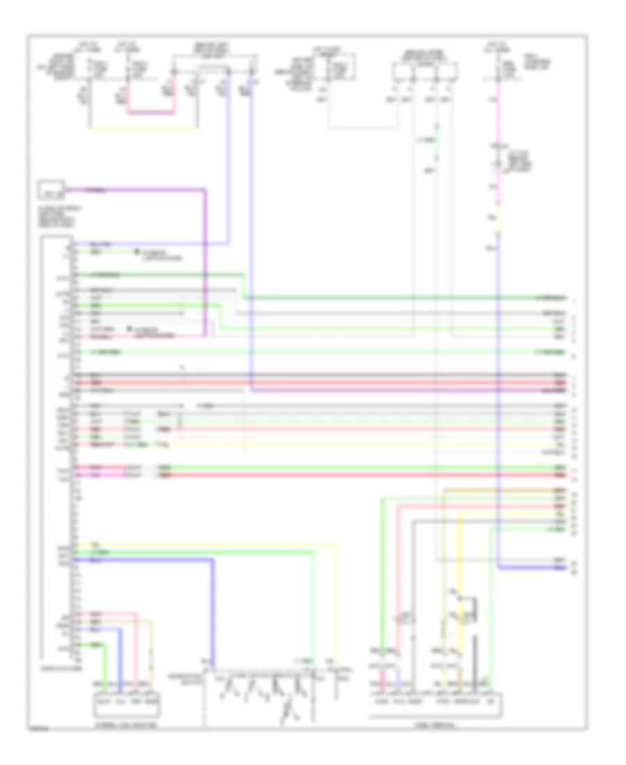
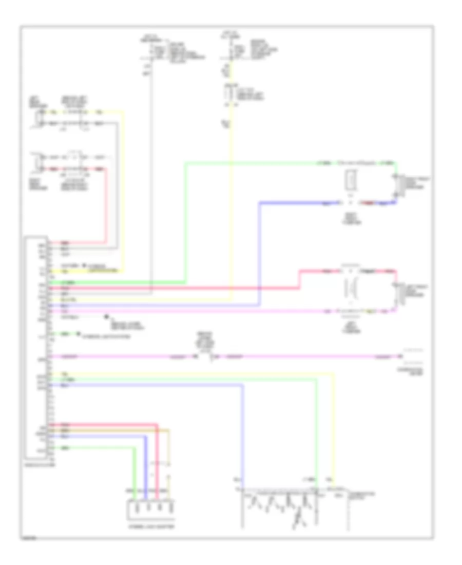
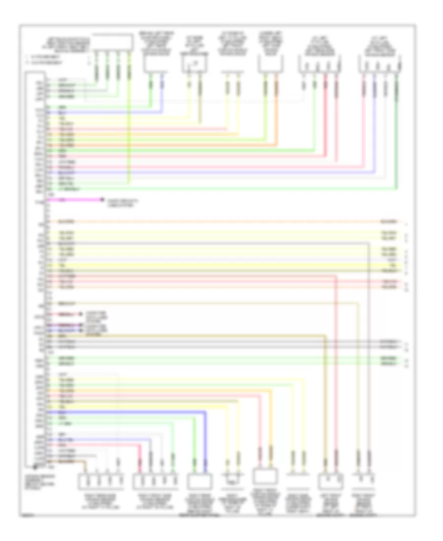
AIR CONDITIONING
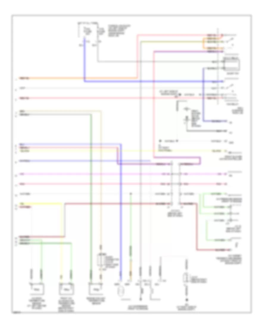
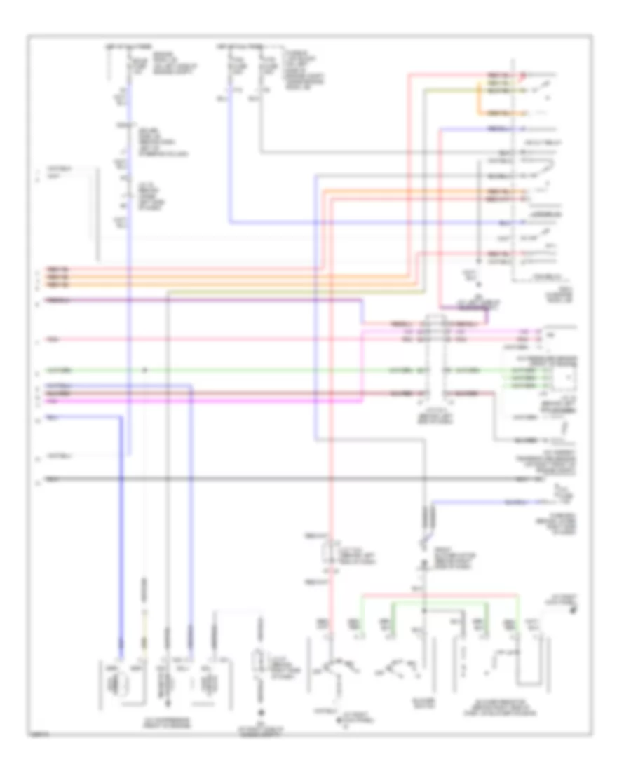
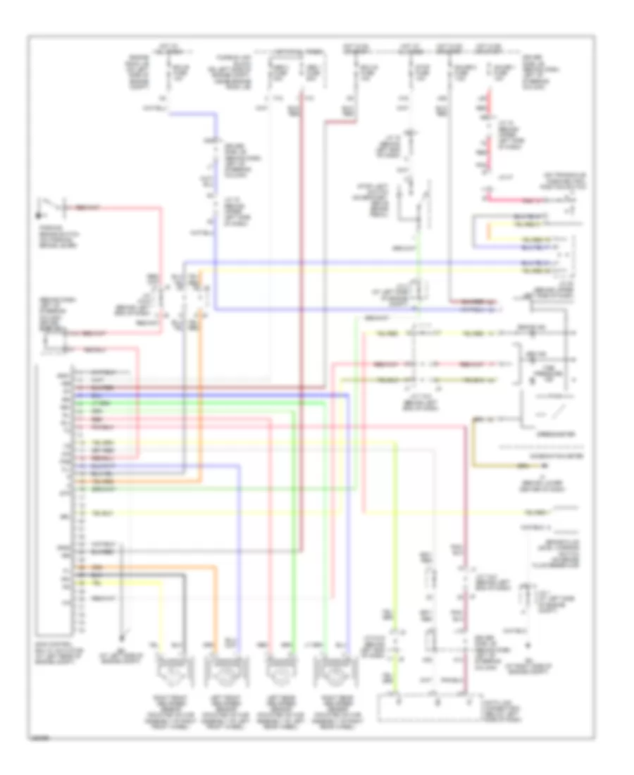
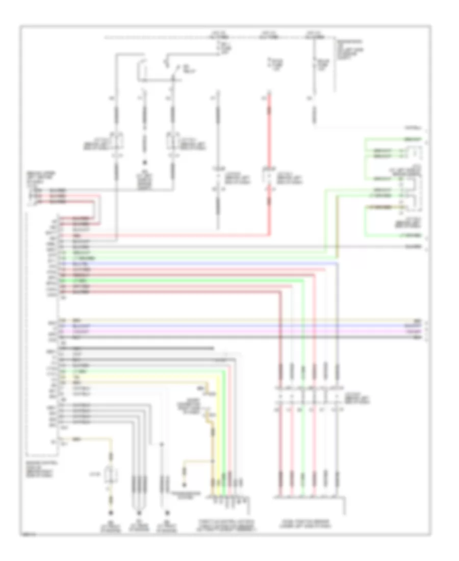
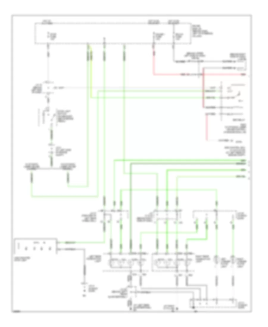
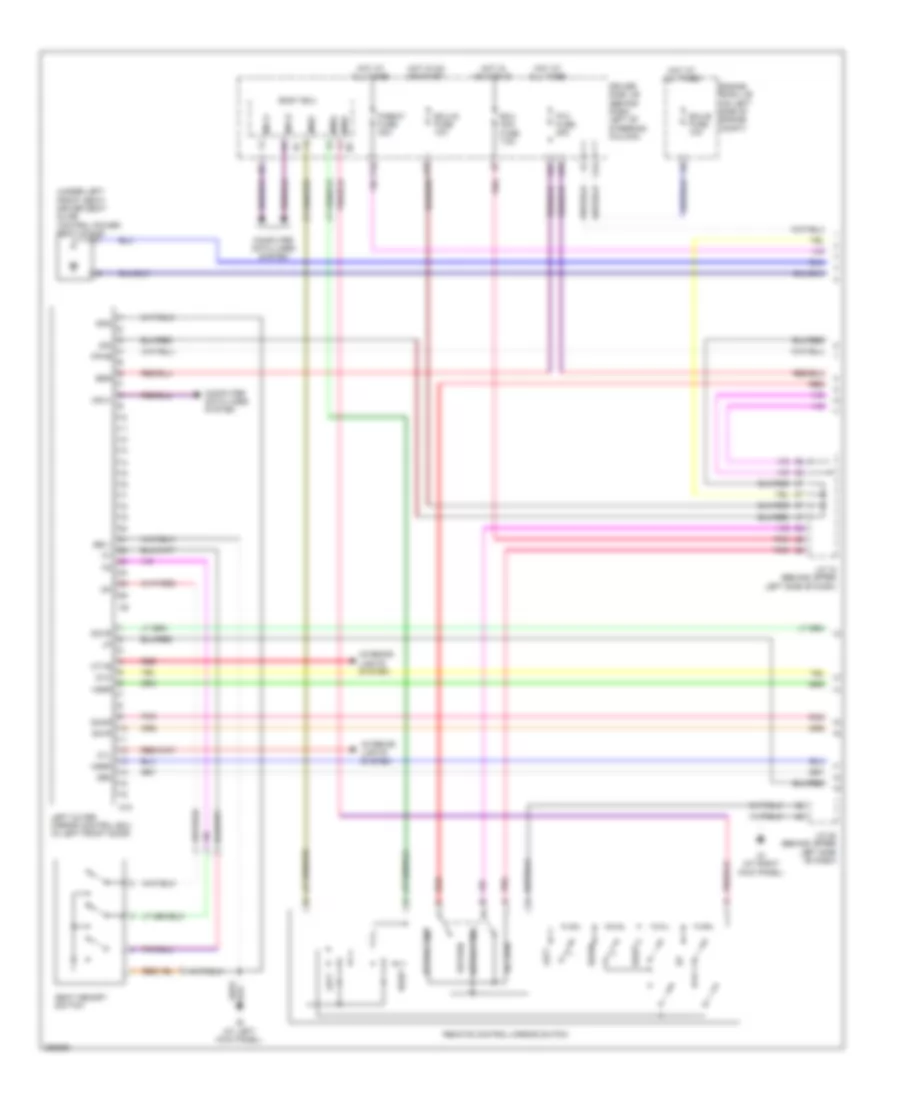
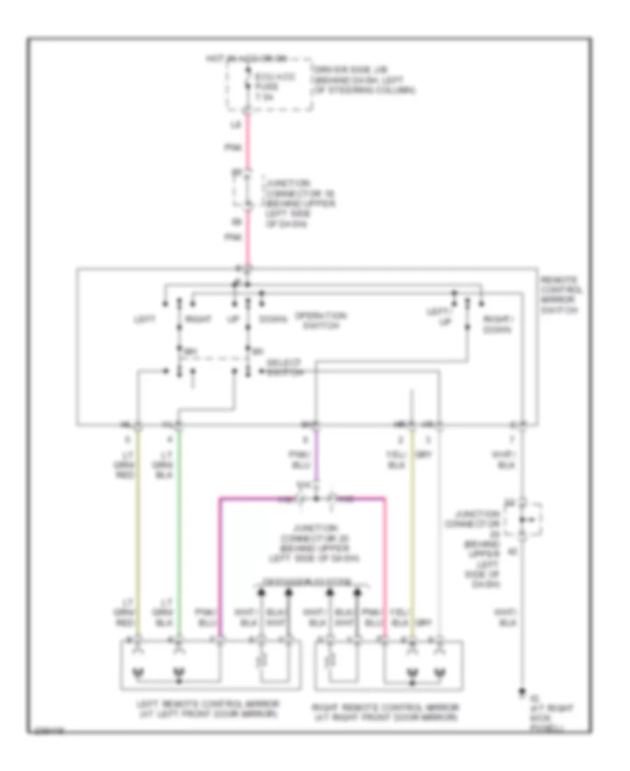
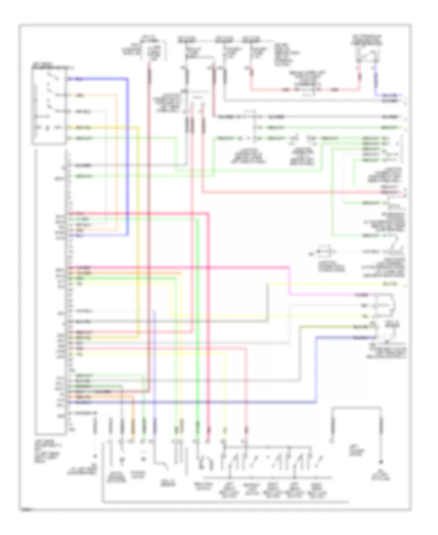
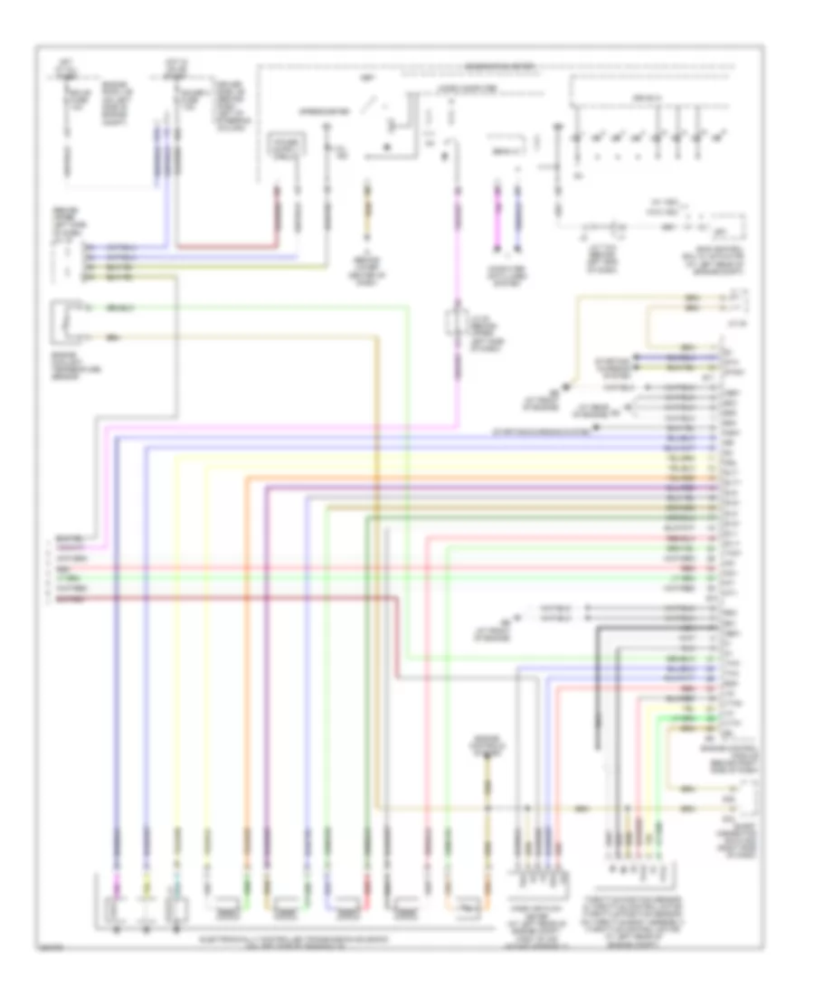
Automatic A/C Wiring Diagram, Front (1 of 2) for Toyota Sienna CE 2007
 https://portal-diagnostov.com/license.html
Automotive Electricians Portal FZCO
Automotive Electricians Portal FZCO
https://portal-diagnostov.com/license.html
https://portal-diagnostov.com/license.html
Automotive Electricians Portal FZCO
Automotive Electricians Portal FZCO
List of elements for Automatic A/C Wiring Diagram, Front (1 of 2) for Toyota Sienna CE 2007:
- (behind left end of dash) j/c 3 & 4
- (behind right side of dash)
- A/c control assembly
- Acc
- Aif
- Air
- Air inlet control servo motor (behind upper right side of dash)
- Amdc
- Amdh
- Ampc
- Amph
- Aod
- Aof
- Automatic light control sensor (on top left side of dash)
- Blw
- C24
- C26
- Canh
- Canl
- Computer data lines system
- Cooling fan ecu (at center front (at center front of engine compt) of engine compt)
- Driver side air mix control servo motor (behind left center of dash)
- Driver side j/b (behind dash, left of steering column)
- E4 e4
- Ecu acc
- Ecu-b fuse 10a
- Ed (at left side of engine compt)
- Engine control
- Engine room j/b (on left side of engine compt)
- Fan motor (main)
- Fan motor (sub)
- Front air vent mode control servo motor (behind left center of dash)
- Front passenger side air mix control servo motor (behind right center of dash)
- Fuse 7.5a
- Gnd
- Hot at all times
- Hot in acc or on
- Htr fuse 10a
- Ie (at left kick panel)
- J/c 18 (behind upper left side of dash)
- J/c 19 (behind upper left side of dash)
- L28
- Lock
- Mgc
- Module
- Mpx+
- Mpx-
- Pnk
- Pre
- Red
- Rfc rfc
- S5-1
- S5-5
- Sg-1
- Sg-4
- Sg-5
- Sg-6
- Sol+
- Tam
- Thw
- Tpd
- Tpi
- Tpo
- Tpp
- Tsd
- Tsl
- Tsp
- Tsr
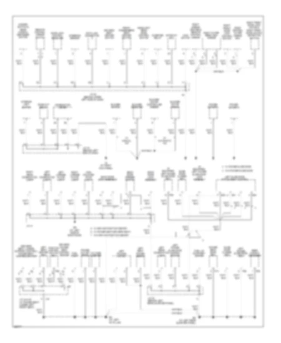
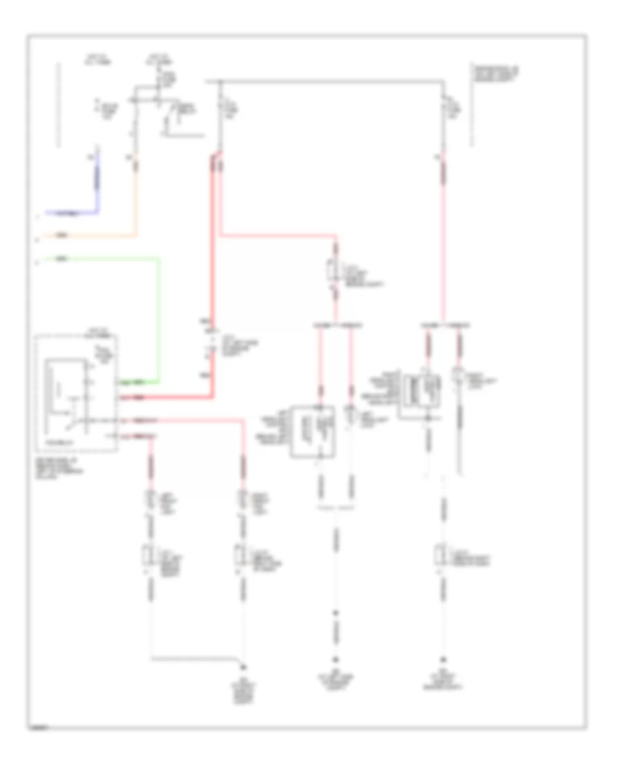
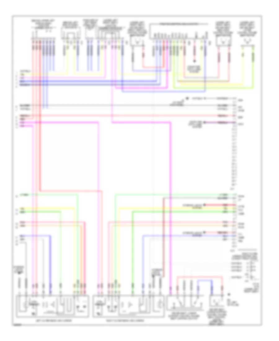
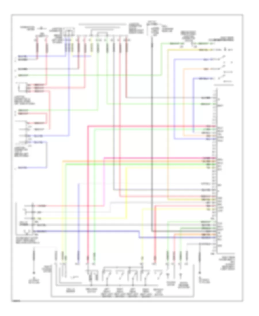
Automatic A/C Wiring Diagram, Front (2 of 2) for Toyota Sienna CE 2007
List of elements for Automatic A/C Wiring Diagram, Front (2 of 2) for Toyota Sienna CE 2007:
- (at left side of engine compt) ed
- A/c ambient temperature sensor (on right front of engine compt)
- A/c compressor (front of engine)
- A/c pressure sensor (front of engine)
- A/c room temperature sensor (at left center of dash)
- A31
- A32
- Ea (at right side of engine compt)
- Engine coolant temperature sensor
- F12
- Fan fuse 50a
- Fan relay
- Front a/c evaporator temperature sensor (behind right side of dash)
- Front blower motor (behind right side of dash)
- Front blower motor controller
- Fusible link block (on left side of engine compt, inside engine room j/b)
- Gnd
- Hot at all times
- Htr fuse 50a
- Ig (at right kick panel)
- J/c 15 (behind left end of dash)
- J/c 27 (behind right side of dash)
- J/c 3 & 4 (behind left end of dash)
- J15
- Mg clt relay
- Mg+
- Pnk
- R/b 3 (in engine room j/b)
- S34
- S35
- Short connector 34 & 35 (right side of dash)
- Short pin
- Sol+
- Sol-
- Ssr+
- Ssr-
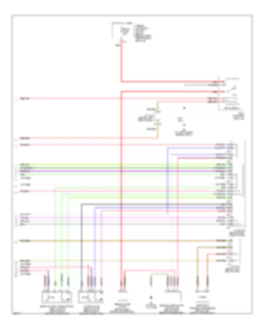
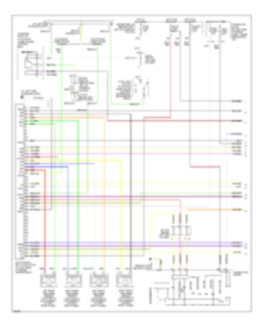
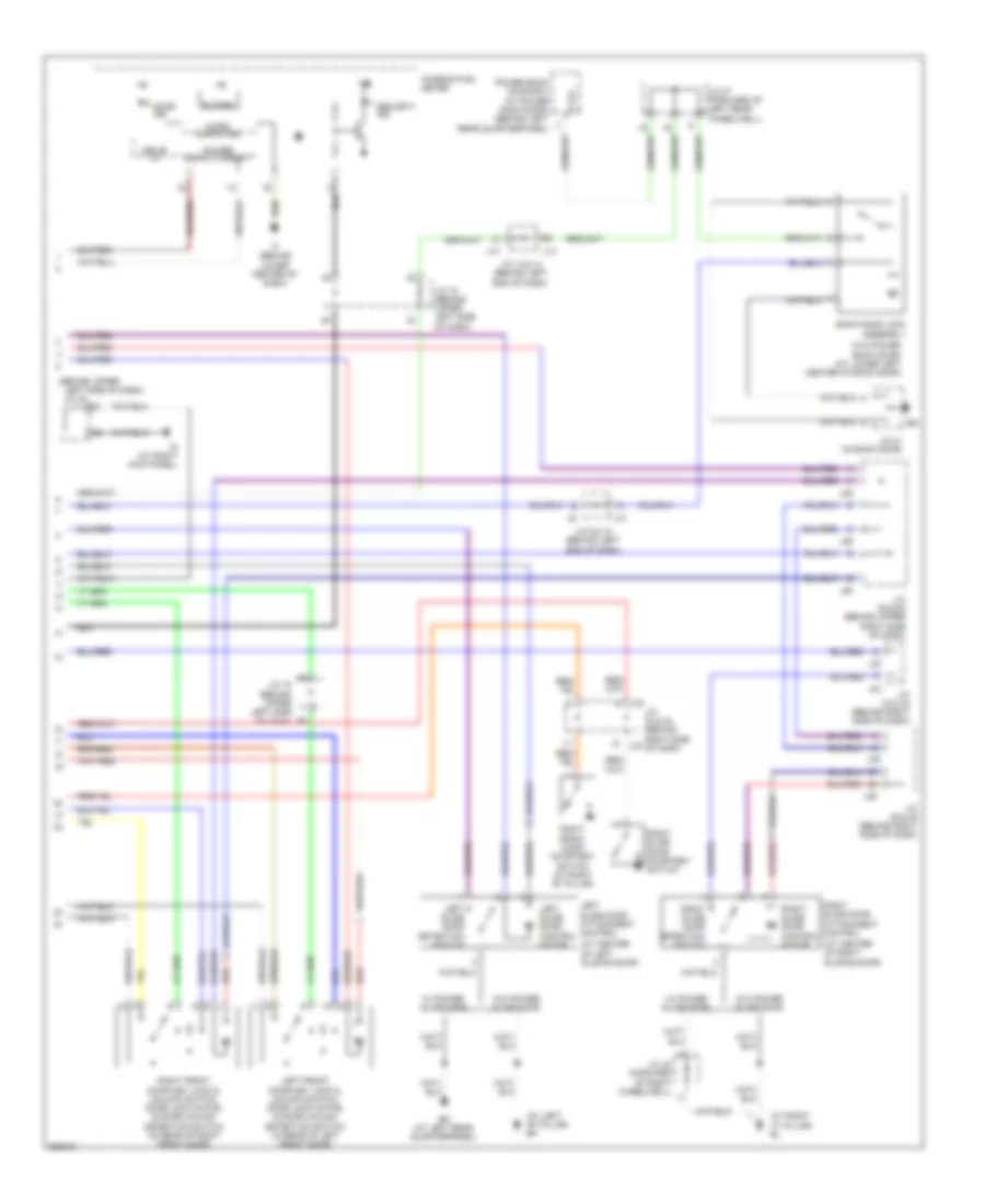
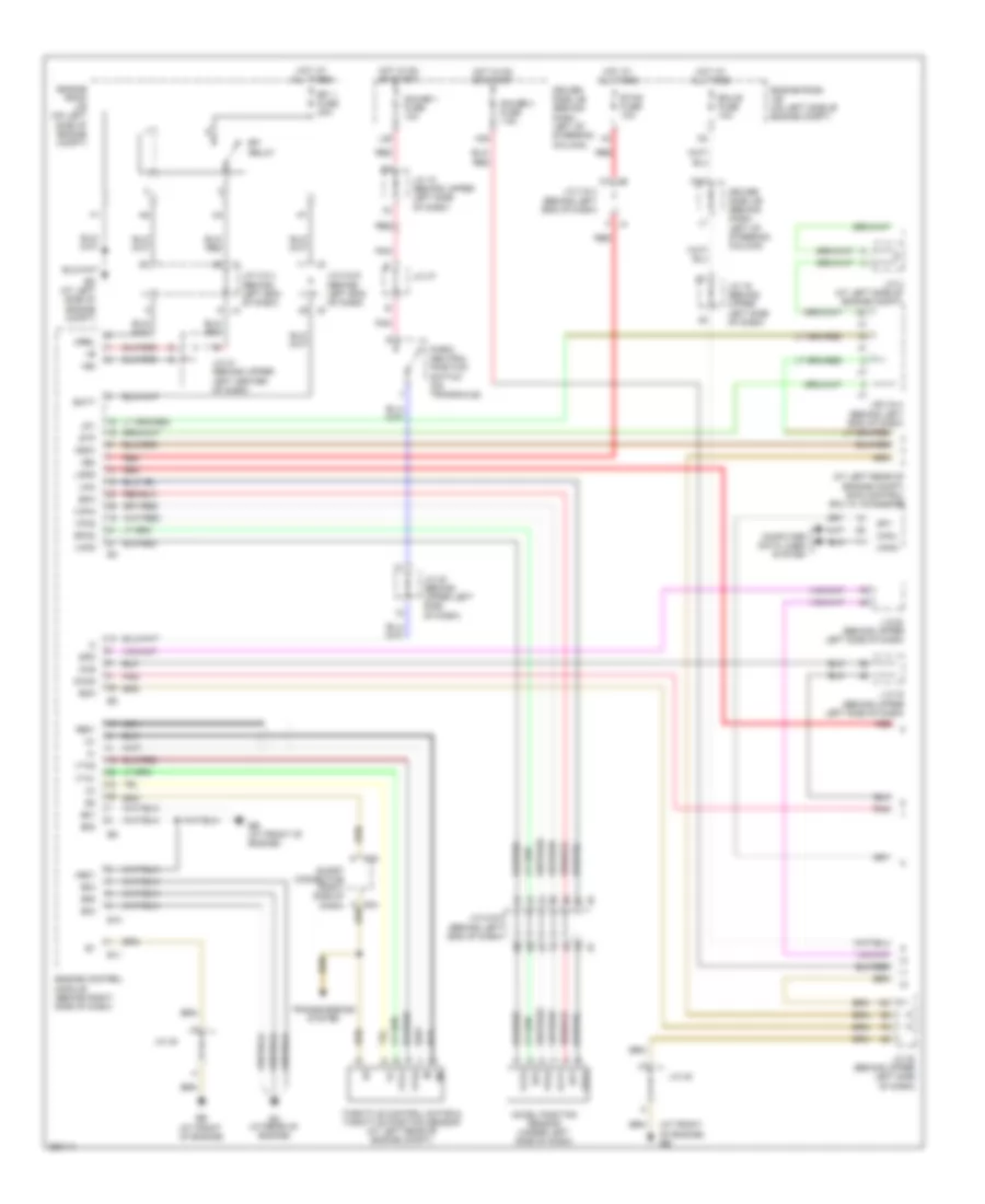
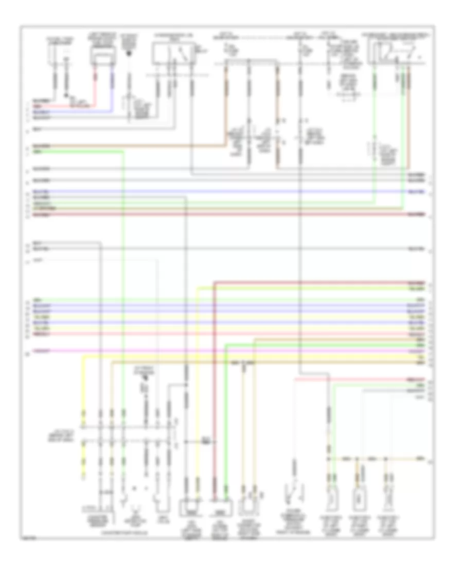
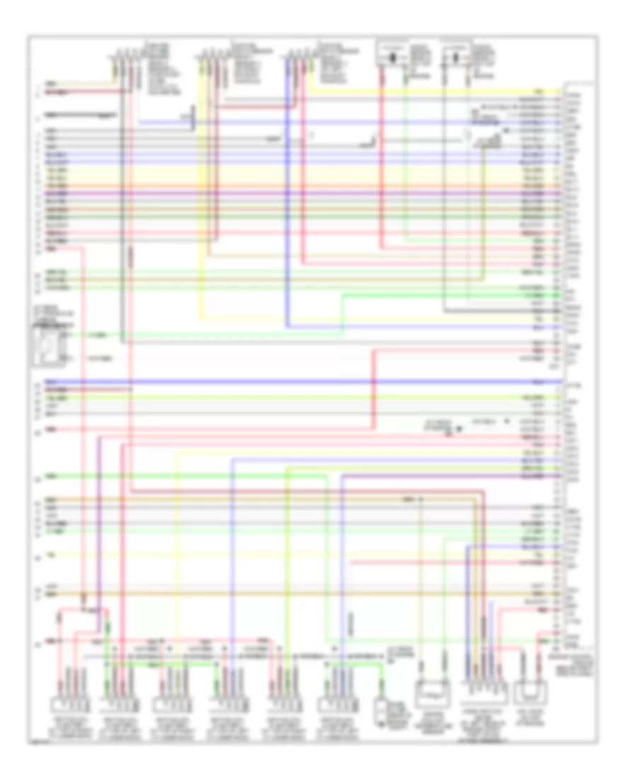
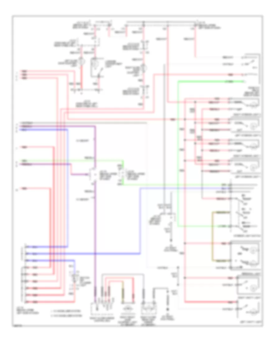
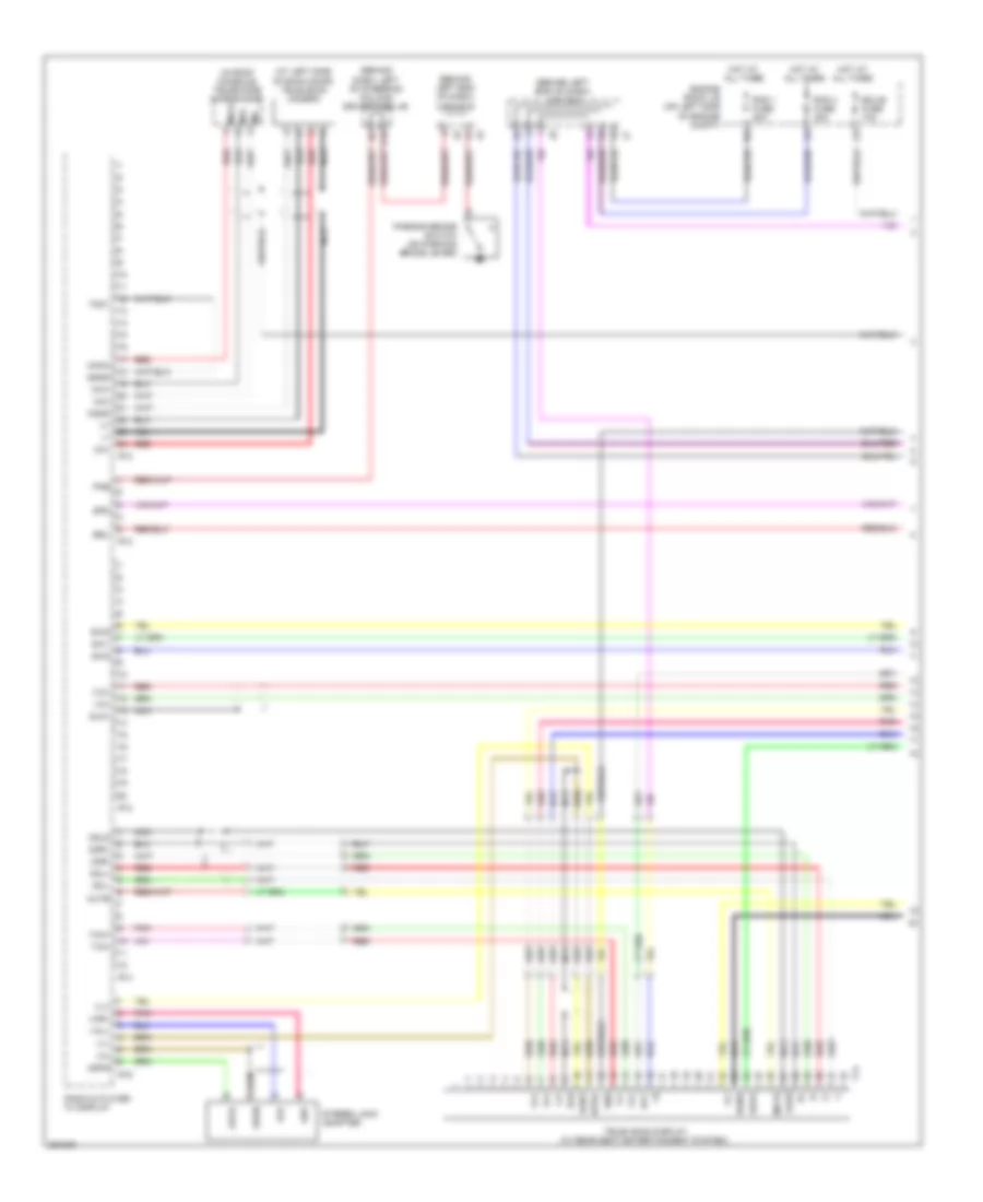
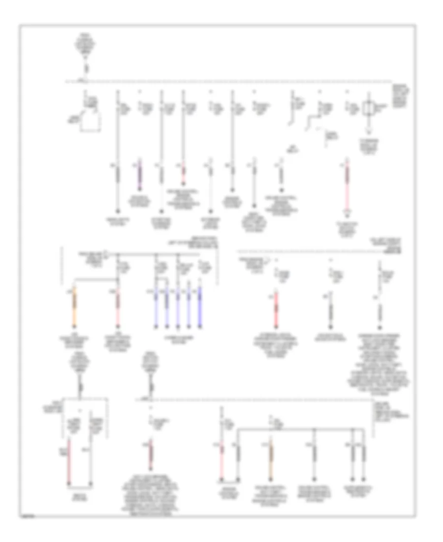
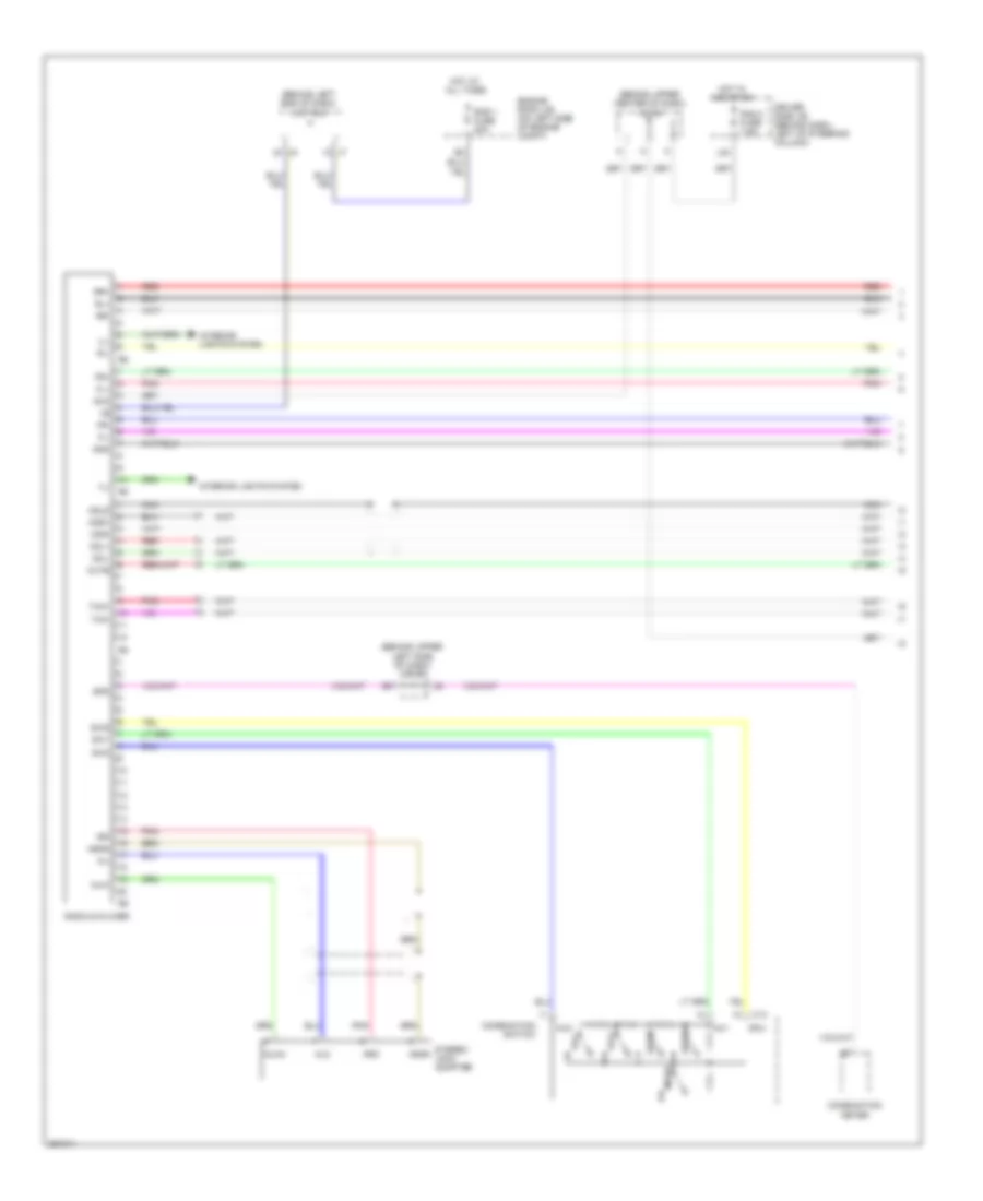
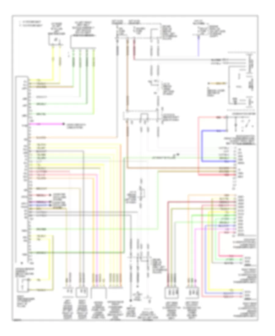
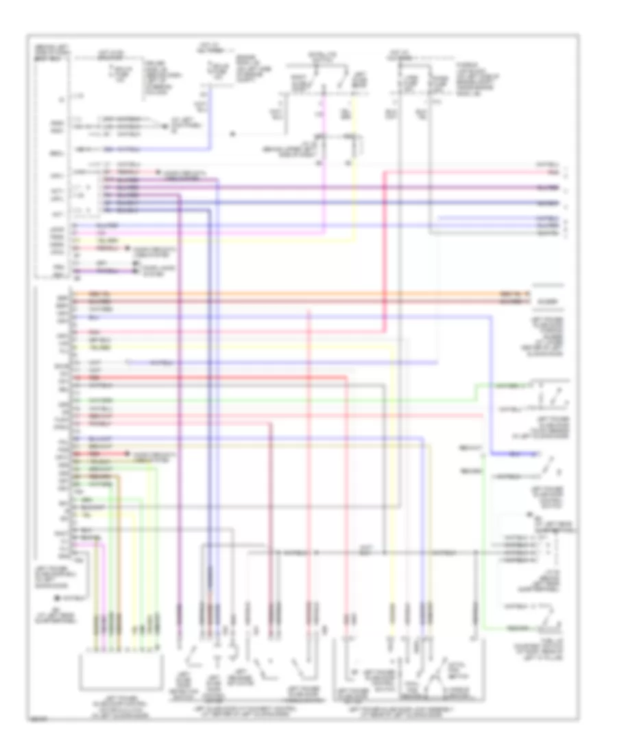
Automatic A/C Wiring Diagram, Rear (1 of 2) for Toyota Sienna CE 2007
List of elements for Automatic A/C Wiring Diagram, Rear (1 of 2) for Toyota Sienna CE 2007:
- A/c control assembly
- A10
- Acc
- Aif
- Air
- Amdc
- Amdh
- Ampc
- Amph
- Aod
- Aof
- Blw
- Blwh
- C24
- C26
- Clk
- Clkr
- Computer data lines system
- Dpd
- Driver side j/b (behind dash, left of steering column)
- Ecu-b fuse 10a
- Engine room j/b (on left side of engine compt)
- Face
- Foot
- Front a/c circuit
- Gnd
- Hot at all times
- Hrh
- Htr fuse 10a
- Ie (at left kick panel)
- Ill
- Ill+
- Ill-
- Interior lights system
- J/c 18 (behind upper left side of dash)
- J/c 19 (behind upper left side of dash)
- J/c 35 & 36 (behind right side of dash)
- J/c 43 (behind right rear quarterpanel)
- J35
- J36
- L28
- Lock
- Mch
- Mgc
- Mhh
- Mpx+
- Mpx-
- Pnk
- Pre
- Rear a/c control switch
- Rear a/c evaporator temperature sensor (behind right rear quarterpanel)
- Red
- S5-1
- S5-5
- Sg-1
- Sg-4
- Sg-5
- Sg-6
- Sgnd
- Sol+
- Stk
- Stx
- Swd
- Tam
- Tec
- Tpd
- Tph
- Tpi
- Tpm
- Tpo
- Tpp
- Tsd
- Tsp
- Vmh
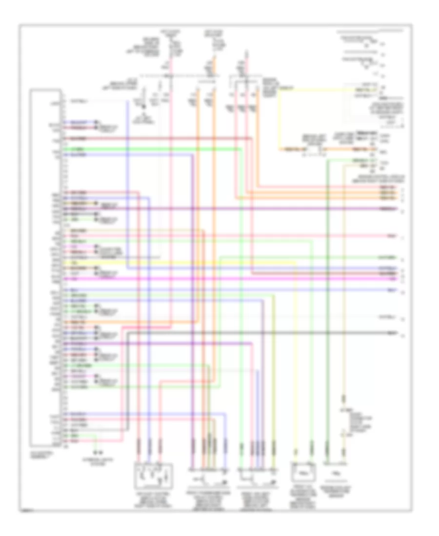
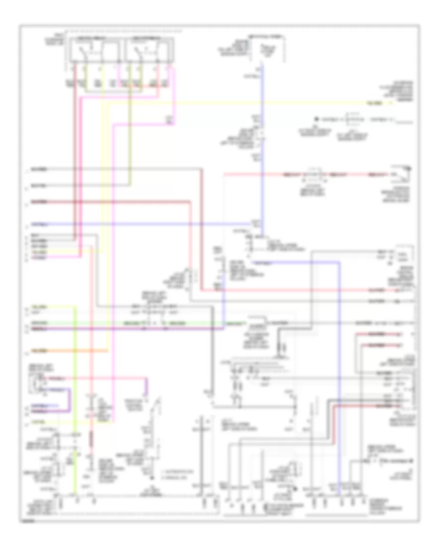
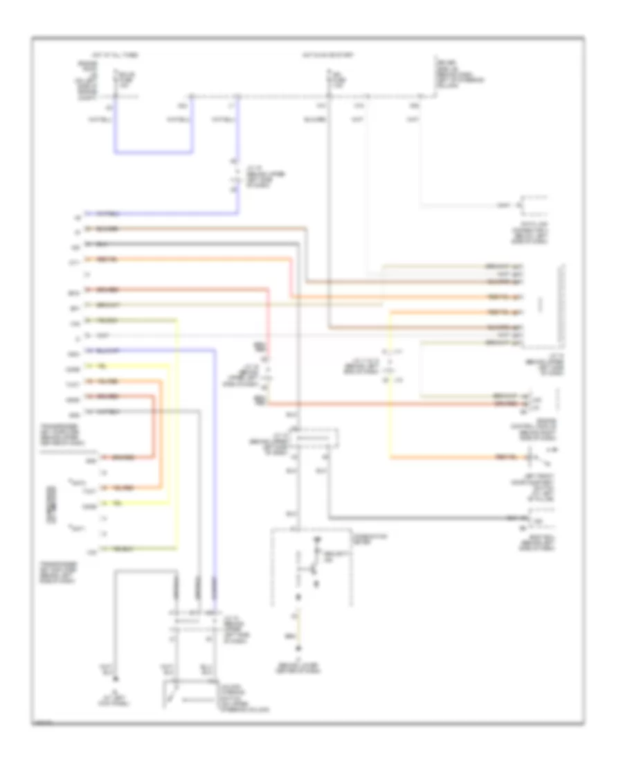
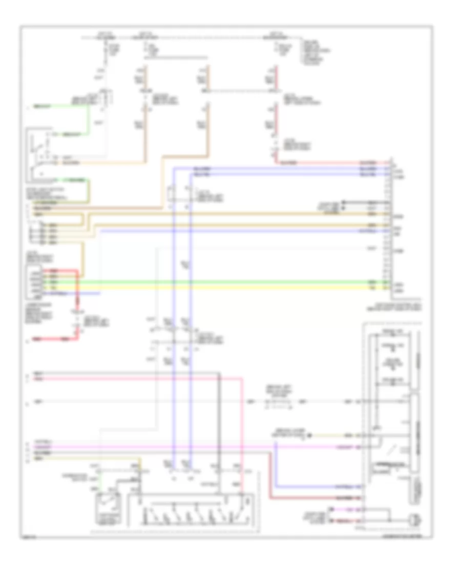
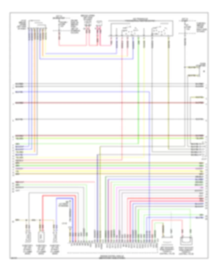
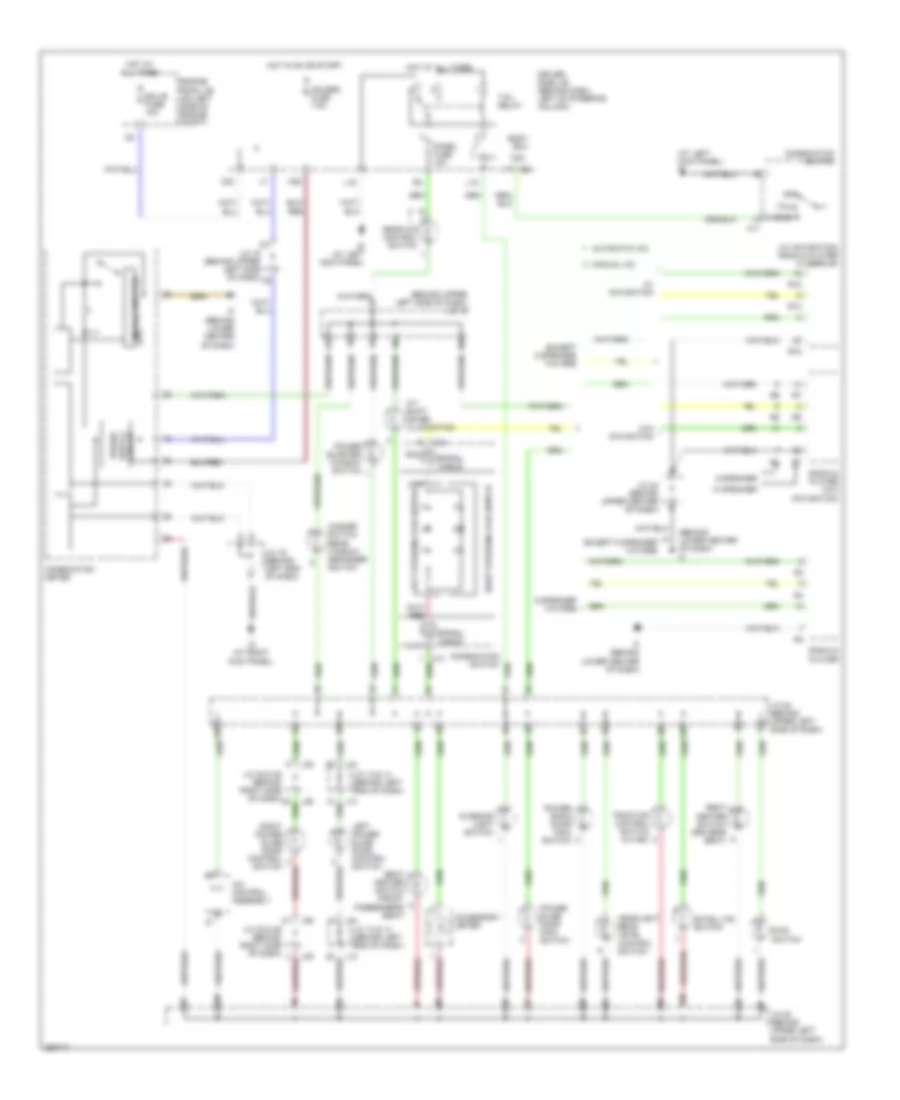
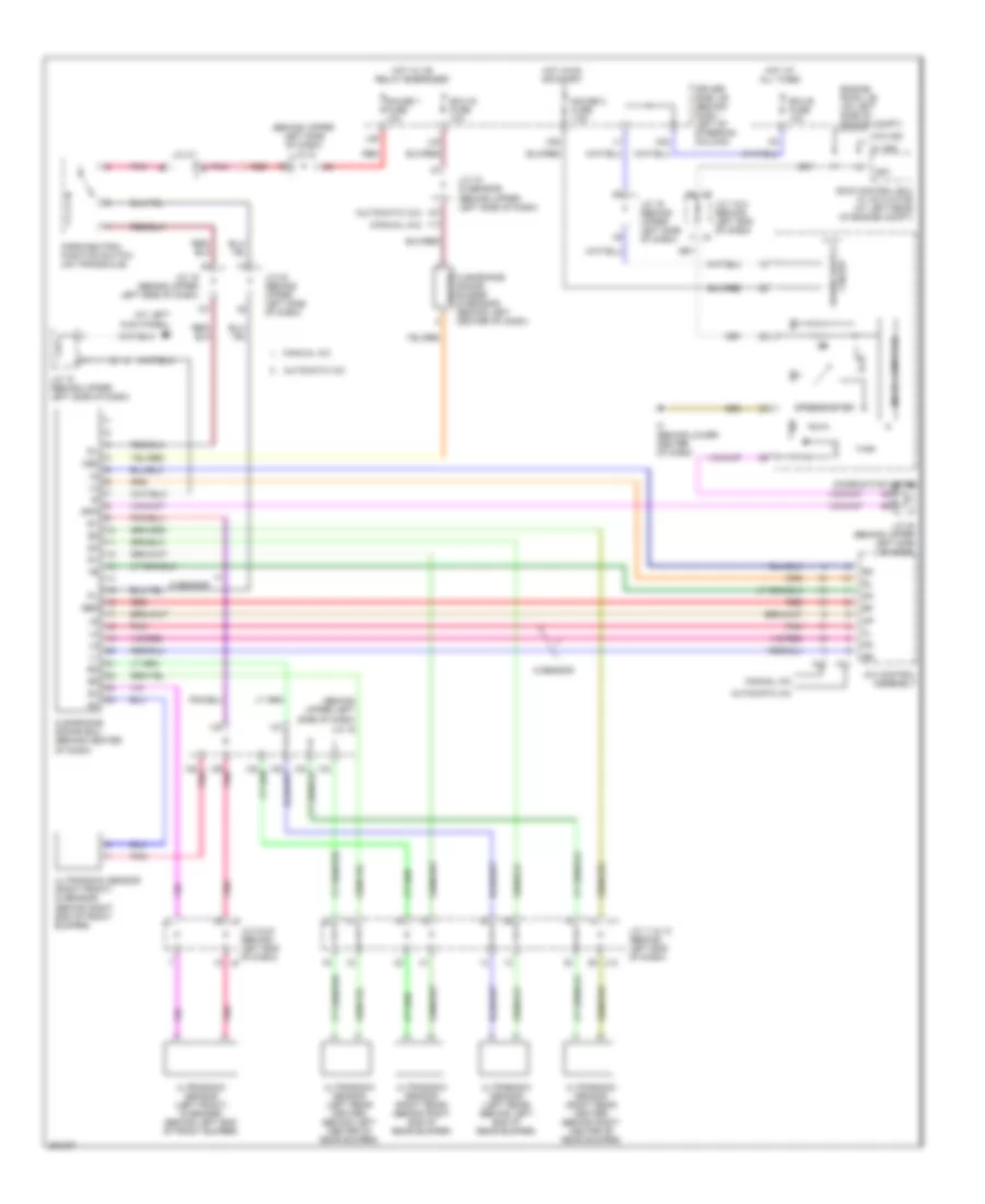
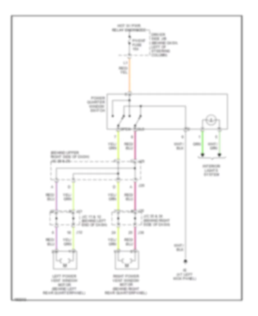
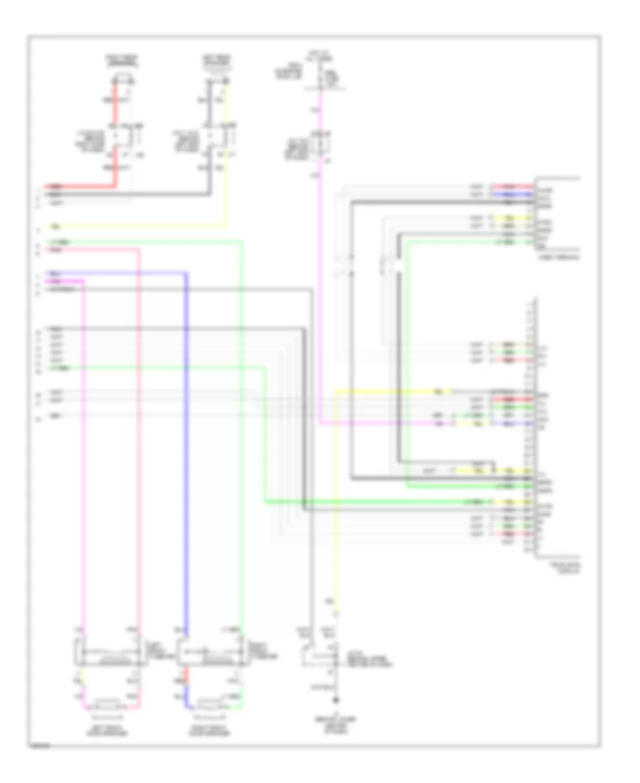
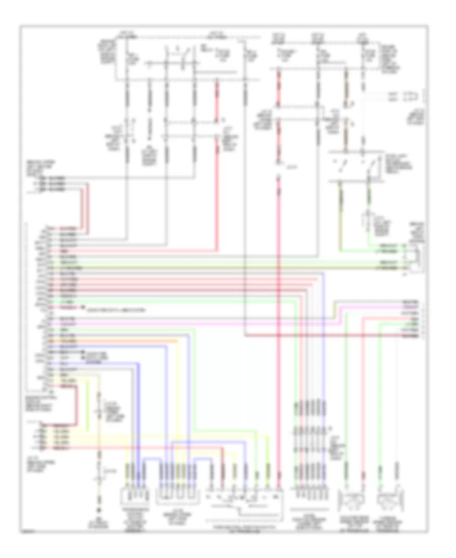
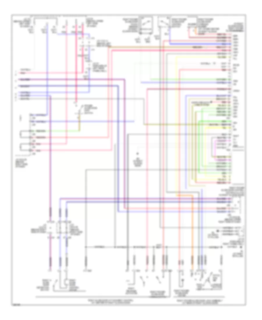
Automatic A/C Wiring Diagram, Rear (2 of 2) for Toyota Sienna CE 2007
List of elements for Automatic A/C Wiring Diagram, Rear (2 of 2) for Toyota Sienna CE 2007:
- Bl (at right "c" pillar)
- Ed (at left side of engine compt)
- F14
- Fusible link block (on left side of engine compt, inside engine room j/b)
- Hot at all times
- J/c 35 & 36 (behind right side of dash)
- J/c 7 & 8 (behind left end of dash)
- J/c 9 & 10 (behind left end of dash)
- J10
- J35
- J36
- R/b 3 (in engine room j/b)
- Rear air vent mode control servo motor (behind right rear quarterpanel)
- Rear blower motor (behind right rear quarterpanel)
- Rear blower motor controller (behind right rear quarterpanel)
- Rear room temperature sensor (behind left rear quarterpanel)
- Red
- Rr a/c fuse 40a
- Rr a/c relay
- Water valve servo motor (behind right rear quarterpanel)
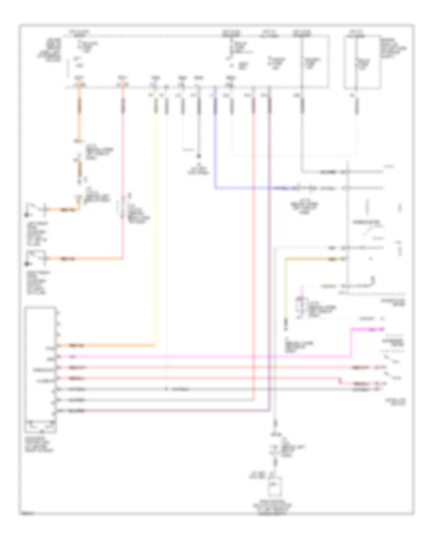
Manual A/C Wiring Diagram, Front (1 of 2) for Toyota Sienna CE 2007
List of elements for Manual A/C Wiring Diagram, Front (1 of 2) for Toyota Sienna CE 2007:
- (behind left end of dash) j/c 3 & 4
- A/c control assembly
- A/cb
- A10
- Acc
- Air inlet control servo motor (behind upper right side of dash)
- Aod
- Aof
- Blin
- Blwc
- Bset
- C26
- Canh
- Canl
- Computer data lines system
- Cooling fan ecu (at center front of engine compt)
- Driver's side j/b (behind dash, left of steering column)
- Ecu acc
- Engine control module (behind right side of dash)
- Engine coolant temperature sensor
- Engine room j/b (on left side of engine compt)
- Face
- Fan motor (main)
- Fan motor (sub)
- Foot
- Front a/c evaporator temperature sensor (behind right side of dash)
- Front air vent mode control servo motor (behind left center of dash)
- Front passenger side air mix control servo motor (behind right center of dash)
- Frs
- Ftin
- Fuse 7.5a
- Gnd
- Hot in acc or on
- Hot in on or start
- Hrc
- Htr fuse 10a
- Ie (at left kick panel)
- Ig+
- Ill+
- Ill-
- Interior lights system
- J/c 18 (behind upper left side of dash)
- L28
- Lock
- Mch
- Mgc
- Mhh
- Mpx+
- Mpx-
- Pnk
- Pre
- Rear a/c circuit
- Rec
- Rfc
- S34
- S35
- S5-1
- S5-5
- Sg-1
- Sg-4
- Sg-6
- Short connector 34 & 35 (right side of dash)
- Sol+
- Tam
- Tcol
- Thot
- Thw
- Tph
- Tpm
- Tpo
- Tset
- Vmc
Manual A/C Wiring Diagram, Front (2 of 2) for Toyota Sienna CE 2007
List of elements for Manual A/C Wiring Diagram, Front (2 of 2) for Toyota Sienna CE 2007:
- (at right kick panel) ig
- A/c ambient temperature sensor (on right front of engine compt)
- A/c compressor (front of engine)
- A/c fuse 7.5a
- A/c pressure sensor (front of engine)
- A31
- A32
- Blower resistor (behind right side of dash, on blower housing)
- Blower switch
- C24
- Clutch magnetic
- Driver side j/b (behind dash, left of steering column)
- Ea (at right side of engine compt)
- Ecu-b fuse 10a
- Ed (at left side of engine compt)
- Engine room j/b (on left side of engine compt)
- F12
- Fan fuse 50a
- Fan relay
- Flow control valve
- Front blower motor (behind right side of dash)
- Fuse box (behind lower right side of dash)
- Fusible link block (on left side of engine compt, inside engine room j/b)
- Hot at all times
- Htr fuse 50a
- Htr relay
- J/c 15 (behind left end of dash)
- J/c 19 (behind upper left side of dash)
- J/c 27 (behind right side of dash)
- J/c 3 & 4 (behind left end of dash)
- J/c 7 & 8 (behind left end of dash)
- J15
- Lock sensor
- Mg clt relay
- Mg+
- Off
- Pnk
- R/b 3 (in engine room j/b)
- Sol+
- Sol-
- Ssr+
- Ssr-
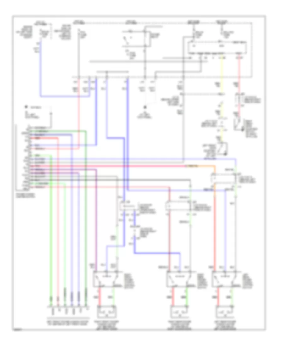
Manual A/C Wiring Diagram, Rear for Toyota Sienna CE 2007
List of elements for Manual A/C Wiring Diagram, Rear for Toyota Sienna CE 2007:
- (behind right rear quarterpanel) rear blower motor controller
- (in engine room j/b)
- A/c control assembly
- A10
- B/l
- B13
- Bl (at right "c" pillar)
- Blin
- Blwc
- Bset
- C24
- C26
- Driver side j/b (behind dash, left of steering column)
- Ecu-b fuse 10a
- Ed (at left side of engine compt)
- Engine room j/b (on left side of engine compt)
- F14
- Face
- Fcin
- Foot
- Ftin
- Fusible link block (on left side of engine compt, inside engine room j/b)
- Gnd
- Hot at all times
- Hot in on or start
- Hrc
- Htr fuse 10a
- Ie (at left kick panel)
- Ig+
- Ill
- Interior lights system
- J/c 18 (behind upper left side of dash)
- J/c 19 (behind upper left side of dash)
- J/c 35 & 36 (behind right side of dash)
- J/c 43 (behind right rear quarterpanel)
- J/c 7 & 8 (behind left end of dash)
- J35
- J36
- L28
- Mch
- Mhh
- R/b 3
- Rear a/c control switch
- Rear air vent mode control servo motor (behind right rear quarterpanel)
- Rear blower motor (behind right rear quarterpanel)
- Red
- Rr a/c fuse 40a
- Rr a/c relay
- Tph
- Tpm
- Tset
- Vmc
- Water valve servo motor (behind right rear quarterpanel)
ANTI-LOCK BRAKES
Anti-lock Brakes Wiring Diagram, with VSC (1 of 2) for Toyota Sienna CE 2007
List of elements for Anti-lock Brakes Wiring Diagram, with VSC (1 of 2) for Toyota Sienna CE 2007:
- (at left side of engine compt) ed
- (in engine room j/b)
- (w/ dynamic laser cruise) control) r/b 6
- +bs
- Abs 1 fuse 50a
- Abs 2 fuse 30a
- Abs ind
- Brake ind
- Brk relay
- Brl
- C16
- C21
- Canh
- Canl
- Combination meter
- Csw
- D/g
- Driver side j/b (behind dash, left of steering column)
- Driver side j/b (behind dash, left of steering column) j6 j/c 5 & 6 (behind left end of dash) j5
- Ecu-ig fuse 10a
- F10
- F12
- Fl+
- Fl-
- Fr+
- Fr-
- Fusible link block (on left side of engine compt, inside engine room j/b)
- Gauge 2 fuse 7.5a
- Gnd1
- Gnd2
- H25
- Hot at all times
- Hot in on or start
- If (behind lower center of dash)
- Ig1
- Ind
- J/c 15 (behind left end of dash)
- J/c 2 (at left side of engine compt) a
- J/c 7 & 8 (behind left end of dash)
- K15
- L23
- Left front abs speed sensor (mounted on hub assembly of left front wheel)
- Left rear abs speed sensor (mounted on hub assembly of left rear wheel)
- Mrf
- Pkb
- Red
- Right front abs speed sensor (mounted on hub assembly of right front wheel)
- Right rear abs speed sensor (mounted on hub assembly of right rear wheel)
- Rl+
- Rl-
- Rr+
- Rr-
- Skid control ecu w/ actuator (at left rear of engine compartment)
- Slip ind
- Speedometer
- Stop fuse 10a
- Stop light switch (w/ dynamic laser cruise control) (on bracket, above brake pedal)
- Stp1
- Stp2
- Stpo
- Tire pressure
- Trac off ind
- Vsc ind
- W/ dynamic laser cruise control
- W/o dynamic laser cruise control
- Wfse
Anti-lock Brakes Wiring Diagram, with VSC (2 of 2) for Toyota Sienna CE 2007
List of elements for Anti-lock Brakes Wiring Diagram, with VSC (2 of 2) for Toyota Sienna CE 2007:
- (behind left end of dash) j/c 5 & 6
- (behind upper left side of dash) j/c 20
- (on brake fluid reservoir) brake fluid level warning switch
- Automatic a/c
- Bat
- Bl (at right "c" pillar)
- Buzzer
- C24
- Canh
- Canl
- Data link connector 3 below left side of dash)
- Driver side j/b (behind dash, left of steering column)
- Ea (at right side of engine compt)
- Ecu-b fuse 10a
- Engine control module (behind right side of dash)
- Engine room j/b (on left side of engine compt)
- Ess
- Gnd
- Hot at all times
- Ie (at left kick panel)
- Ig (at right kick panel)
- Ig1
- J/c 1 (at left side of engine compt)
- J/c 17 (behind upper left side of dash)
- J/c 18 (behind upper left side of dash)
- J/c 19 (behind upper left side of dash)
- J/c 28 (behind right side of dash)
- J/c 31 & 32 (behind right side of dash)
- J/c 42 (forward of right wheelwell) a
- J/c 49
- J/c 5 & 6 (behind left end of dash)
- J31
- J32
- J7 j/c 7 & 8 (behind left j8 end of dash)
- K10
- K28
- Manual a/c
- Parking brake switch (on parking brake lever)
- R/b 5 (in engine room j/b)
- Sil
- Steering sensor (inside steering column)
- Traction control switch
- Vsc fail relay
- Vsc mtr relay
- Vsc warning buzzer (behind left side of dash)
- Wsfe
- Yaw rate sensor (under right front seat)
Anti-lock Brakes Wiring Diagram, without VSC for Toyota Sienna CE 2007
List of elements for Anti-lock Brakes Wiring Diagram, without VSC for Toyota Sienna CE 2007:
- (behind dash, left of steering column) driver side j/b
- (on transaxle) park/neutral position switch
- +bm
- +bs
- Abs 1 fuse 50a
- Abs 2 fuse 30a
- Abs ind
- Brake fluid level warning switch (on brake fluid reservoir)
- Brake ind
- Brl
- C16
- C24
- Combination meter
- D/g
- Data link connector 3 (below left side of dash)
- Driver side j/b (behind dash, left of steering column)
- Ea (at right side of engine compt)
- Ecu-b fuse 10a
- Ecu-ig fuse 10a
- Ed (at left side of engine compt)
- Engine room j/b (on left side of engine compt)
- F10
- F12
- Fl+
- Fl-
- Fr+
- Fr-
- Fusible link block (on left side of engine compt, inside engine room j/b)
- Gauge 1 fuse 10a
- Gauge 2 fuse 7.5a
- Gnd1
- Gnd2
- H25
- Hot at all times
- Hot in on or start
- If (behind lower center of dash)
- Ig1
- J/c 1 (at left side of engine compt)
- J/c 15 (behind left end of dash)
- J/c 18 (behind upper left side of dash)
- J/c 19 (behind upper left side of dash)
- J/c 2 (at left side of engine compt)
- J/c 20 (behind upper left side of dash)
- J/c 47
- J/c 5 & 6 (behind left end of dash)
- J/c 7 & 8 (behind left end of dash)
- K10
- K14
- K28
- L10
- L26
- Left front abs speed sensor (mounted on hub assembly of left front wheel)
- Left rear abs speed sensor (mounted on hub assembly of left rear wheel)
- Parking brake switch (on parking brake lever)
- Pkb
- Pnk
- Red
- Right front abs speed sensor (mounted on hub assembly of right front wheel)
- Right rear abs speed sensor (mounted on hub assembly of right rear wheel)
- Rl+
- Rl-
- Rr+
- Rr-
- Sil
- Skid control ecu w/ actuator (at left rear of engine compt)
- Speedometer
- Stop fuse 10a
- Stop light switch (on bracket, above brake pedal)
- Stp
- Tire pressure ind
ANTI-THEFT
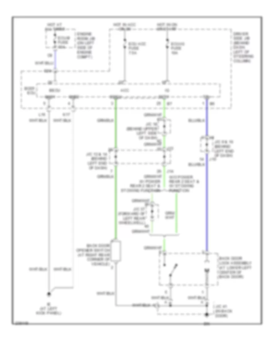
Forced Entry Wiring Diagram (1 of 2) for Toyota Sienna CE 2007
List of elements for Forced Entry Wiring Diagram (1 of 2) for Toyota Sienna CE 2007:
- (at left kick panel) ie
- (at right side of engine compt) ea
- Acc
- Act+
- Act-
- Actd
- Altb
- Bcty
- Becu
- Body ecu (behind left side of dash)
- Buzzer
- Bzr
- C24
- C25
- C30
- Dcty
- Door 2 fuse 25a
- Door lock control receiver (behind upper center of dash)
- Driver side j/b (behind dash, left of steering column)
- Ecu acc fuse 7.5a
- Ecu-b fuse 10a
- Ecu-ig fuse 10a
- Ehw
- Engine hood courtesy switch (center front of engine compt)
- Engine room j/b (on left side of engine compt)
- Gauge 2 fuse 7.5a
- Gnd
- Gnd2
- H25
- Haz
- Hcty
- Horn
- Horns system
- Hot at all times
- Hot in acc or on
- Hot in on or start
- Ie (at left kick panel)
- Ig (at right kick panel)
- Ind
- J/c 1 (at left side of engine compt)
- J/c 11 & 12 (behind left end of dash)
- J/c 18 (behind upper left side of dash)
- J/c 19 (behind upper left side of dash)
- J/c 20 (behind upper left side of dash)
- J/c 3 & 4 (behind left end of dash)
- J11
- J12
- K17
- K22
- K25
- K26
- Keyless buzzer (behind left front corner lamp)
- Ksw
- Lcty
- Left front door courtesy switch (at left "b" pillar)
- Left slide door courtesy switch
- Lock
- Lock left front door lock control switch
- Lswd
- Lswl
- Lswp
- Lswr
- P17
- P19
- Pcty
- Prg
- Rcty
- Rda
- Right front door lock control switch
- Theft deterrent horn (on right rear of engine compt)
- Tr+
- Turn signal flasher (behind left side of dash)
- Ul1
- Ul2
- Ul3
- Unlock
- Unlock warning switch (on upper steering column)
Forced Entry Wiring Diagram (2 of 2) for Toyota Sienna CE 2007
List of elements for Forced Entry Wiring Diagram (2 of 2) for Toyota Sienna CE 2007:
- (at center of left sliding door)
- (at center of right sliding door)
- (at left "b" pillar) bh
- (at right "c" pillar) bl
- (behind upper
- (w/o power back door) (at lower left center of back door)
- Back door lock assembly
- Bm (at left rear quarterpanel)
- Buzzer
- Combination meter
- Ctyo
- Door ind
- Drive ic
- If (behind lower center of dash)
- Ig (at right kick panel)
- J/c 13 & 14 (behind left end of dash)
- J/c 18 (behind upper left side of dash)
- J/c 20
- J/c 25 & 26 (behind upper right side of dash)
- J/c 33 & 34 (behind right side of dash)
- J/c 35 & 36 (behind right side of dash)
- J/c 37 (forward of left rear wheelwell)
- J/c 41 (in back door)
- J/c 42 (forward of right wheelwell)
- J/c 9 & 10 (behind left end of dash)
- J10
- J13
- J14
- J25
- J26
- J33
- J33 j/c 33 & 34 (behind right side j34 of dash)
- J34
- J35
- J36
- Left front door key lock & unlock switch, door lock motor, & door unlock detection switch (in rear of left front door)
- Left side of dash)
- Left slide door attachment control
- Left slide door control motor
- Left slide door detection switch
- Micro computer
- Power back door ecu (w/ power back door) (behind left rear quarterpanel)
- Red
- Right front door courtesy switch (at right "b" pillar)
- Right front door key lock & unlock switch, door lock motor, & door unlock detection switch (in rear of right front door)
- Right slide door attachment control
- Right slide door control motor
- Right slide door courtesy switch
- Right slide door detection switch
- Security ind
- W/ power slide door
- W/o power slide door
Immobilizer Wiring Diagram for Toyota Sienna CE 2007
List of elements for Immobilizer Wiring Diagram for Toyota Sienna CE 2007:
- Agnd
- Ant1
- Ant2
- Body ecu (behind left side of dash)
- C24
- Code
- Combination meter
- Cty
- Data link connector 3 (below left side of dash)
- Driver side j/b (behind dash, left of steering column)
- Ecu-b fuse 10a
- Efii
- Efio
- Engine control module (behind right side of dash)
- Engine room j/b (on left side of engine compt)
- Gnd
- H12
- H13
- Hot at all times
- Hot in on or start
- Ie (at left kick panel)
- If (behind lower center of dash)
- Ign fuse 7.5a
- Imi
- Imo
- Ind
- J/c 11 & 12 (behind left end of dash)
- J/c 18 (behind upper left side of dash)
- J/c 19 (behind upper left side of dash)
- J11
- J12
- K28
- Key amplifier transponder
- Ksw
- Left front door courtesy switch (at left "b" pillar)
- Security ind
- Transponder key amplifier (behind left side of dash)
- Transponder key computer (behind upper center of dash)
- Txct
- Unlock warning switch (on upper steering column)
- Vc5
BODY CONTROL MODULES
Body Control Modules Wiring Diagram (1 of 2) for Toyota Sienna CE 2007
List of elements for Body Control Modules Wiring Diagram (1 of 2) for Toyota Sienna CE 2007:
- (at left kick panel) ie
- (behind dash, left of steering column) driver side j/b
- A/c control assembly
- A21
- Acc
- Act+
- Act-
- Actd
- Air bag sensor assembly (below center of dash)
- Altb
- Automatic a/c
- Bcty
- Bdsu
- Becu
- Body ecu (behind left side of dash)
- C10
- C23
- C24
- C25
- C30
- Combination meter
- Dcty
- Dcyl
- Door 2 fuse 25a
- Door locks & interior lights systems
- Door locks & trunk, tailgate, fuel doors systems
- Door locks system
- Drl
- Dsds
- Ecu acc fuse 7.5a
- Ecu-b fuse 10a
- Ecu-ig fuse 10a
- Engine room j/b (on left side of engine compartment)
- Exterior lights system
- Gnd1
- Gnd2
- H30
- H32
- Headlights & exterior lights systems
- Headlights system
- Horn
- Horns system
- Hot at all times
- Hot in acc or on
- Hot in on or start
- Hrly
- Ie (at left kick panel)
- Ile
- Interior lights system
- K10
- K17
- K22
- K25
- K26
- L16
- Lcty
- Left outer mirror control ecu (w/ memory) (in left front door)
- Lswd
- Lswl
- Lswp
- Lswr
- Manual a/c
- Mpx+
- Mpx-
- Mpx1
- Mpx2
- O11
- P17
- P19
- Pbds
- Pcty
- Pcyl
- Pkb
- Power tops system
- Prg
- Psds
- Pwr relay
- Pws
- Rcty
- Rcut
- Rda
- Right outer mirror control ecu (w/ memory) (in right front door)
- Trly
- Trunk, tailgate, fuel doors & interior lights systems
- Trunk, tailgate, fuel doors system
- Ul1
- Ul2
- Ul3
Body Control Modules Wiring Diagram (2 of 2) for Toyota Sienna CE 2007
List of elements for Body Control Modules Wiring Diagram (2 of 2) for Toyota Sienna CE 2007:
- Anti-theft system
- Body ecu (behind left side of dash)
- Bzr
- Cltb
- Clte
- Clts
- Data link connector 3 (below left side of dash)
- Door locks & anti-theft systems
- Door locks & warning systems
- Door locks system
- Driver side j/b (behind dash, left of steering column)
- Exterior lights system
- Ffgo
- Ffog
- Gateway ecu (left side of dash)
- H12
- Haz
- Hcty
- Head
- Headlights system
- Ind
- J/c 13 & 14 (behind left end of dash)
- J/c 18 (behind upper left side of dash)
- J/c 19 (behind upper left side of dash)
- J/c 35 & 36 (behind right side of dash)
- J/c 37 (forward of left rear wheelwell)
- J/c 44 & 45 (under left front seat)
- J13
- J14
- J35
- J36
- J44
- J45
- K28
- Ksw
- Left power slide door ecu (in left sliding door)
- Mirb
- Mire
- Mirrors system
- Mirs
- Mpd1
- Mpd2
- Mpx1
- Obd2
- Position control ecu & switch (w/ memory) (under left side of driver's seat)
- Power back door ecu (behind left rear quarterpanel)
- Red
- Right power slide door ecu (in right sliding door)
- Sil
- Tail
- Tr+
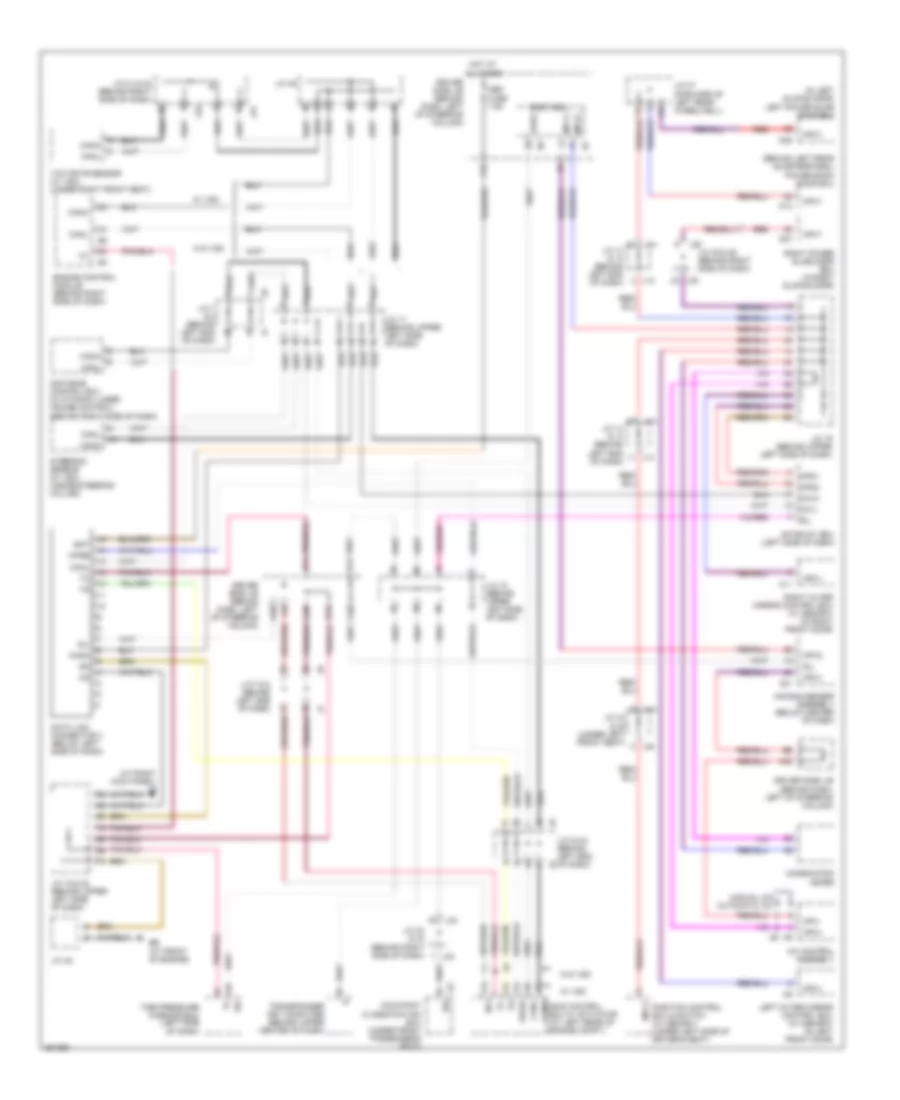
COMPUTER DATA LINES
Computer Data Lines Wiring Diagram for Toyota Sienna CE 2007
List of elements for Computer Data Lines Wiring Diagram for Toyota Sienna CE 2007:
- (at front of engine)
- (at right kick panel) ig
- (behind left rear quarterpanel) power back door ecu
- (in left sliding door) left power slide door ecu
- A/c control assembly
- A21
- Air bag sensor assembly (below center of dash)
- Bat
- Body ecu
- Ca1h
- Ca1l
- Canh
- Canh skid control ecu w/ actuator (at left rear of engine compt)
- Canl
- Combination meter
- D/g
- Data link connector 3 (below left side of dash)
- Dia
- Distance control ecu (w/ dynamic laser cruise control) (behind right side of dash)
- Driver side j/b (behind dash, left of steering column)
- E10
- Engine control module (behind right side of dash)
- Gateway ecu (left side of dash)
- H12
- H32
- H34
- Hot at all times
- J/c 13 & 14 (behind left end of dash)
- J/c 17 (behind upper left side of dash)
- J/c 18 (behind upper left side of dash)
- J/c 19 & 20 (behind upper left side of dash)
- J/c 19 (behind upper left side of dash)
- J/c 31 & 32 (behind right side of dash)
- J/c 33 & 34 (behind right side of dash)
- J/c 35 & 36 (behind right side of dash)
- J/c 37 (forward of left rear wheelwell)
- J/c 44 & 45 (under left front seat)
- J/c 48
- J/c 49
- J/c 5 & 6 (behind left end of dash)
- J/c 7 & 8 (behind left end of dash)
- J13
- J14
- J31
- J32
- J33
- J34
- J35
- J36
- J44
- J45 h
- K12
- K14
- K28
- L10
- Left outer mirror control ecu (w/ memory) (in left front door)
- Manual a/c automatic a/c
- Mpd1
- Mpd2
- Mpx+
- Mpx-
- Mpx1
- Mpx2
- O11
- Obd fuse 7.5a
- Obd2
- Occupant classification ecu (under front passenger's seat)
- P13
- P25
- P27
- Position control ecu & switch (w/ memory) (under left side of driver's seat)
- Red
- Right outer mirror control ecu (w/ memory) (in right front door)
- Right power slide door ecu (in right sliding door)
- Sil
- Steering sensor (w/ vsc) (inside steering column)
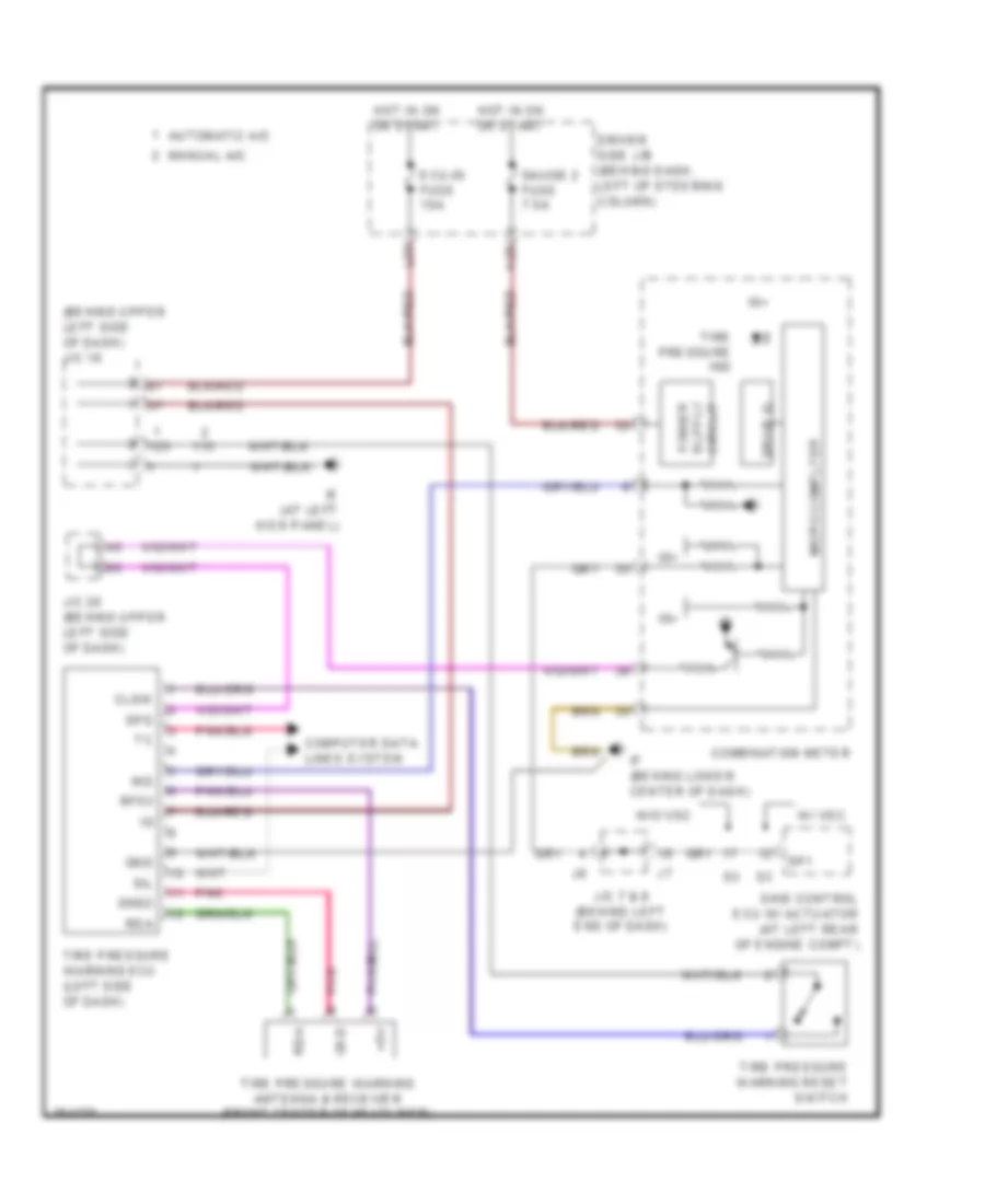
- Tire pressure warning ecu (left side of dash)
- Transponder key computer (behind upper center of dash)
- W/ vsc
- W/o vsc
- Wfse
- Yaw rate sensor (w/ vsc) (under right front seat)
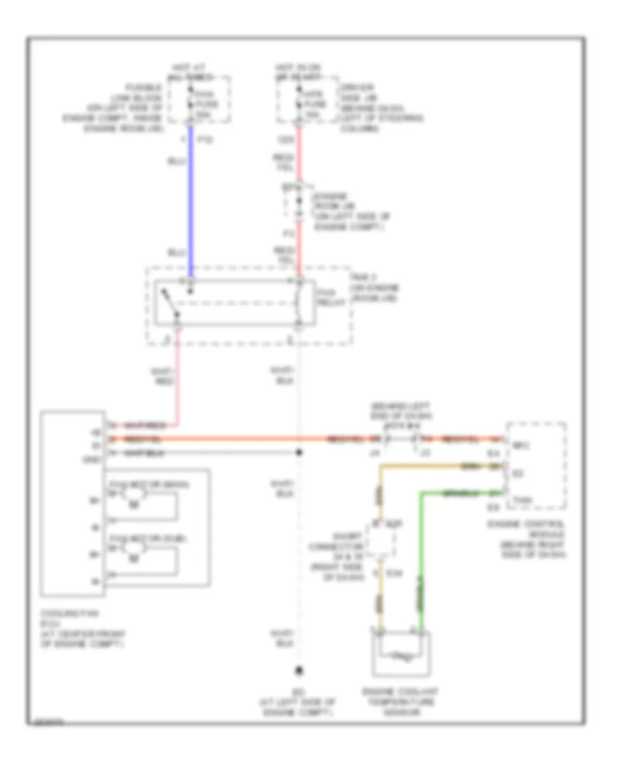
COOLING FAN
Cooling Fan Wiring Diagram for Toyota Sienna CE 2007
List of elements for Cooling Fan Wiring Diagram for Toyota Sienna CE 2007:
- (behind left end of dash) j/c 3 & 4
- C26
- Cooling fan ecu (at center front of engine compt)
- Driver side j/b (behind dash, left of steering column)
- Ed (at left side of engine compt)
- Engine control module (behind right side of dash)
- Engine coolant temperature sensor
- Engine room j/b (on left side of engine compt)
- F12
- Fan fuse 50a
- Fan motor (main)
- Fan motor (sub)
- Fan relay
- Fusible link block (on left side of engine compt, inside engine room j/b)
- Gnd
- Hot at all times
- Hot in on or start
- Htr fuse 10a
- R/b 3 (in engine room j/b)
- Rfc
- S34
- S35
- Short connector 34 & 35 (right side of dash)
- Thw
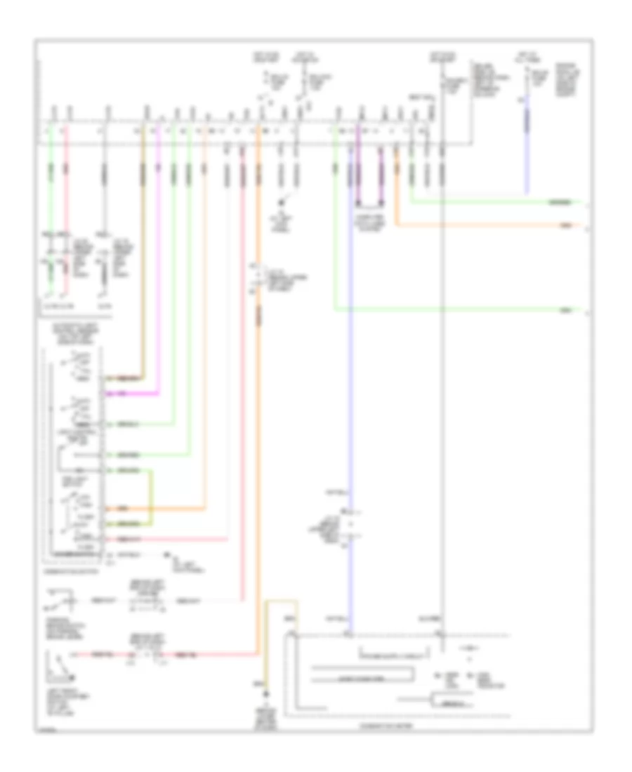
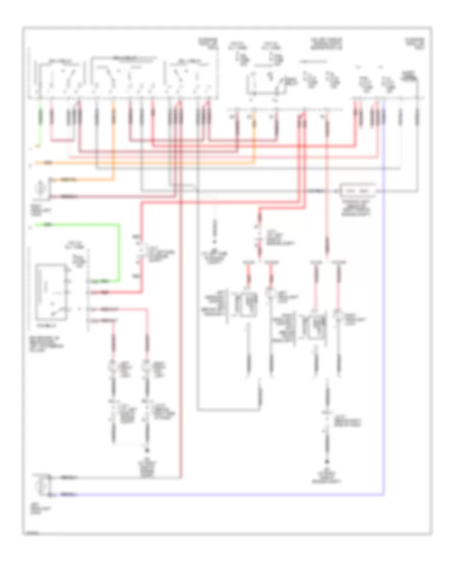
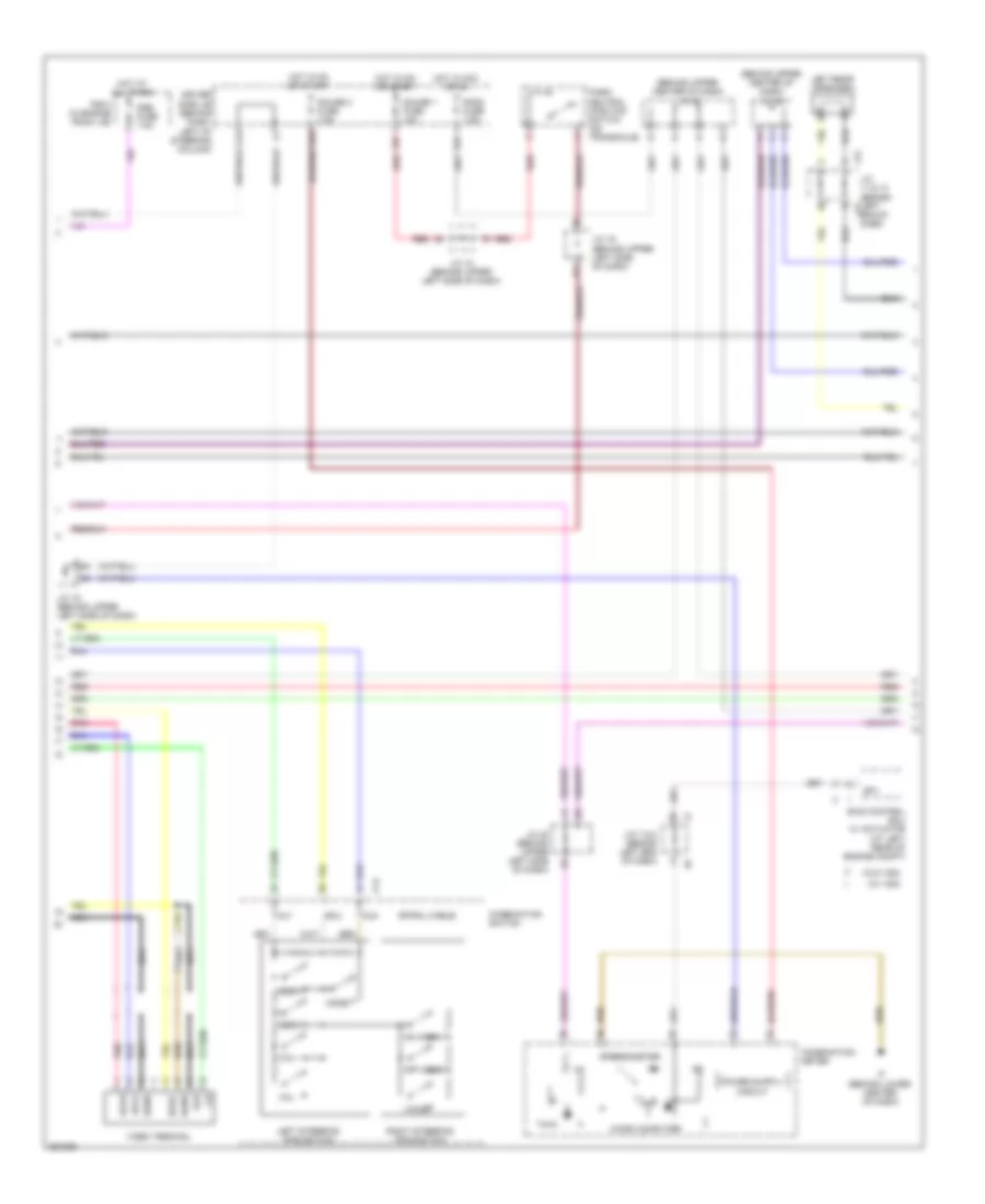
CRUISE CONTROL
Cruise Control Wiring Diagram (1 of 2) for Toyota Sienna CE 2007
List of elements for Cruise Control Wiring Diagram (1 of 2) for Toyota Sienna CE 2007:
- (behind upper left center of dash) j/c 21
- +b2
- +bm
- Accel position sensor (under left side of dash)
- Batt
- Ccs
- E01
- E02
- E03
- E04
- E05
- E10
- E11
- Eb (at front of engine)
- Ec (at rear of engine)
- Ecu-b fuse 10a
- Ed (at left side of engine compt)
- Efi 1 fuse 20a
- Efi relay
- Engine control module (behind right side of dash)
- Engine room j/b (on left side of engine compt)
- Eom
- Epa
- Epa2
- Etcs fuse 10a
- Geo1
- Hot at all times
- Igsw
- J/c 2 (at left side of engine compt)
- J/c 3 & 4 (behind left end of dash)
- J/c 48
- J/c 5 & 6 (behind left end of dash)
- Me01
- Mrel
- Nca
- Red
- S34
- S35
- Short connector (right side of dash)
- Spd
- St1-
- Stp
- Throttle control motor & throttle position sensor (on throttle body assembly)
- Transmissions system
- Vcp2
- Vcpa
- Vpa
- Vpa2
- Vta1
- Vta2
Cruise Control Wiring Diagram (2 of 2) for Toyota Sienna CE 2007
List of elements for Cruise Control Wiring Diagram (2 of 2) for Toyota Sienna CE 2007:
- (behind left end of dash)
- (behind upper left side of dash)
- +res
- -set
- Bean ic
- Cancel
- Combination meter
- Combination switch
- Computer data lines system
- Cruise control switch
- Cruise ind
- Driver ic
- Driver side j/b (behind dash, left of steering column)
- Eb (at front of engine)
- Gauge 1 fuse 10a
- Gauge 2 fuse 7.5a
- Hot at all times
- Hot in on or start
- If (behind lower center of dash)
- Ign fuse 7.5a
- J/c 15
- J/c 18 (behind upper left side of dash)
- J/c 19
- J/c 19 (behind upper left side of dash)
- J/c 20 (behind upper left side of dash)
- J/c 47
- J/c 48
- J/c 5 & 6 (behind left end of dash)
- L26 red
- Micro computer
- On-off
- Park/neutral position switch (on transaxle)
- Pnk
- Red
- Stop fuse 10a
- Stop light switch (on bracket, above brake pedal)
Dynamic Laser Cruise Control Wiring Diagram (1 of 2) for Toyota Sienna CE 2007
List of elements for Dynamic Laser Cruise Control Wiring Diagram (1 of 2) for Toyota Sienna CE 2007:
- (at front of engine)
- (at front of engine) eb
- (at left rear of engine compt) skid control ecu w/ actuator
- +b2
- +bm
- Accel position sensor (under left side of dash)
- Batt
- C24
- Canh
- Canl
- Cchg
- Ccs
- Computer data lines system
- Driver side j/b (behind dash, left of steering column)
- E01
- E02
- E03
- E04
- E05
- E10
- E11
- Eb (at front of engine)
- Ec (at rear of engine)
- Ecu-b fuse 10a
- Ed (at left side of engine compt)
- Efi 1 fuse 20a
- Efi relay
- Engine control module (behind right side of dash)
- Engine room j/b (on left side of engine compt)
- Eom
- Ep1
- Ep2
- Epa
- Epa2
- Etcs fuse 10a
- Gauge 1 fuse 10a
- Gauge 2 fuse 7.5a
- Ge01
- H25
- Hot at all times
- Hot in on or start
- Igsw
- J/b 3 & 4 (behind left end of dash)
- J/c 18 (behind upper left side of dash)
- J/c 19 (behind upper left side of dash)
- J/c 2 (at left side of engine compt)
- J/c 20 (behind upper left side of dash)
- J/c 21 (behind upper left center of dash)
- J/c 3 & 4 (behind left end of dash)
- J/c 47
- J/c 48
- J/c 5 & 6 (behind left end of dash)
- L26
- Lgnd
- Me01
- Mrel
- Nca
- Park/ neutral position switch (on transaxle)
- Pnk
- Red
- S34
- S35
- Short connector (right side of dash)
- Sp1
- Spd
- Sti
- Stp
- Throttle control motor & throttle position sensor (at left rear of engine compt)
- Transmissions system
- Vcp1
- Vcp2
- Vcpa
- Vpa
- Vpa1
- Vpa2
- Vta1
- Vta2
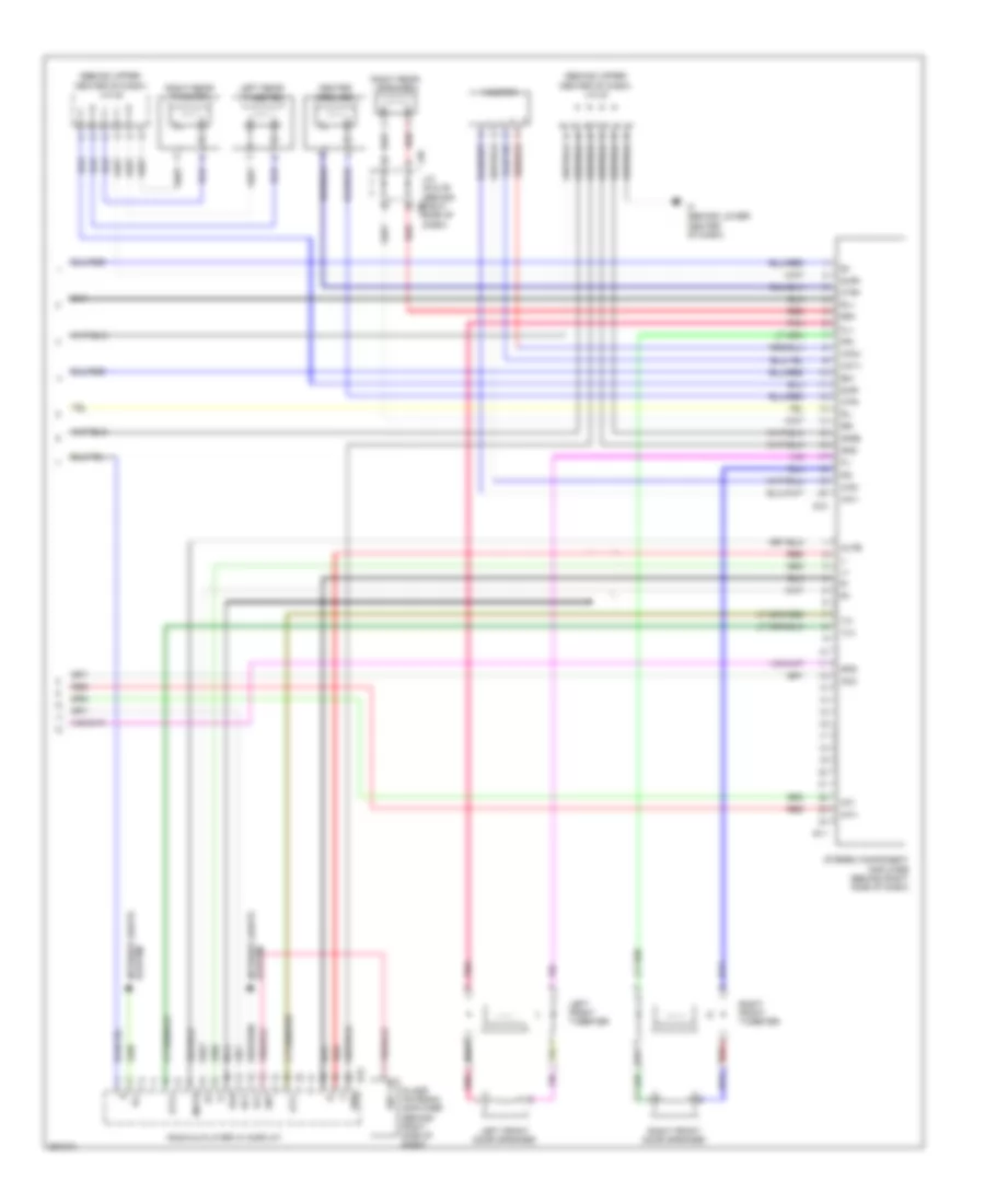
Dynamic Laser Cruise Control Wiring Diagram (2 of 2) for Toyota Sienna CE 2007
List of elements for Dynamic Laser Cruise Control Wiring Diagram (2 of 2) for Toyota Sienna CE 2007:
- (behind left end of dash) j/c 7 & 8
- (behind lower center of dash) if
- +res
- -set
- Bean ic
- Buzzer
- C10
- C12
- C13
- C16
- Cancel
- Ccs
- Combination meter
- Combination switch
- Computer data lines system
- Cruise check ind
- Cruise ind
- Dist
- Distance control ecu (behind right side of dash)
- Distance control switch
- Drive ic
- Driver side j/b (behind dash, left of steering column)
- Ecc
- Ecu-ig fuse 10a
- Gnd
- H13
- Hot at all times
- Hot in on or start
- Igb
- Ign fuse 7.5a
- J/c 15 (behind left end of dash)
- J/c 18 (behind upper left side of dash)
- J/c 28 (behind right side of dash)
- J/c 3 & 4 (behind left end of dash)
- J/c 5 & 6 (behind left end of dash)
- K30
- L23
- Laser radar sensor (behind right side of front bumper)
- Lgnd
- Lrdd
- Lrrd
- Micro computer
- Mode
- Normal ind
- On/off
- Pnk
- R/n
- Ready ind
- Red
- Sgnd
- Speedometer
- Stop fuse 10a
- Stop light switch (on bracket, above brake pedal)
- Wash
- Wip2
DEFOGGERS
Defoggers Wiring Diagram for Toyota Sienna CE 2007
List of elements for Defoggers Wiring Diagram for Toyota Sienna CE 2007:
- A/c control assembly
- A10
- Automatic a/c
- Bm (at left rear quarterpanel)
- C26
- Def fuse 40a
- Defog relay
- Driver side j/b (behind dash, left of steering column)
- Ea (at right side of engine compt)
- Ed (at left side of engine compt)
- Engine room j/b (on left side of engine compt)
- F14
- Fr def fuse 15a
- Front window deicer
- Front window deicer relay (behind left side of dash)
- Fusible link block (on left side of engine compt, inside engine room j/b)
- Hot at all times
- Hot in on or start
- Htr fuse 10a
- Ie (at left kick panel)
- Ig (at right kick panel)
- Ill
- Interior lights system
- J/c 1 (at left side of engine compt)
- J/c 18 (behind upper left side of dash)
- J/c 20 (behind upper left side of dash)
- J/c 3 & 4 (behind left end j4 of dash)
- J/c 7 & 8 (behind left end of dash)
- J12
- K16
- L28
- Left mirror heater (at left front door mirror)
- Left outer rear view mirror (in driver's door)
- Manual a/c
- Mir htr fuse 10a
- P25
- R31
- R32
- Rdsw
- Rear window defogger
- Rear window defogger switch
- Right mirror heater (at right front door mirror)
- Right outer rear view mirror (in right front door)
- W/ memory
- W/o memory
ENGINE PERFORMANCE
3.5L
3.5L, Engine Performance Wiring Diagram (1 of 6) for Toyota Sienna CE 2007
List of elements for 3.5L, Engine Performance Wiring Diagram (1 of 6) for Toyota Sienna CE 2007:
- (at front of engine) eb
- (at left side of engine compt) ed
- (behind left end of dash) j/c 3 & 4
- (behind upper left side of dash) j/c 20
- +b2
- +bm
- A/f fuse 25a
- Accel position sensor (under left side of dash)
- Alt
- At4
- Atl
- Batt
- C/ opn relay
- Canh
- Canl
- Computer data lines system
- Efi 1 fuse 20a
- Efi 2 fuse 10a
- Efi relay
- Efii
- Efio
- Els
- Engine control module (behind right side of dash)
- Engine room j/b (on left side of engine compt)
- Eom
- Ep1
- Ep2
- Epa
- Epa2
- Etcs fuse 10a
- Fuel pump relay
- Hot at all times
- Igsw
- Ill
- Imi
- Imo
- Interior lights system
- J/c 18 (behind upper left side of dash)
- J/c 19 (behind upper left side of dash)
- J/c 21 (behind upper left center of dash)
- J/c 3 & 4 (behind left end of dash)
- J/c 48
- J/c 5 & 6 (behind left end of dash)
- J/c 5 & 6 (behind left end of dash) j5
- Mpmp
- Mrel
- Nssd
- Nssl
- Power distribution system
- Ppmp
- Red
- Spd
- St1-
- Starting/ charging system
- Stp
- Tach
- Transmission control switch (at base of shifter assembly)
- Transponder key computer (behind upper center of dash)
- Vcp1
- Vcp2
- Vcpa
- Vpa
- Vpa1
- Vpa2
- Vpmp
3.5L, Engine Performance Wiring Diagram (2 of 6) for Toyota Sienna CE 2007
List of elements for 3.5L, Engine Performance Wiring Diagram (2 of 6) for Toyota Sienna CE 2007:
- (at front of engine) eb
- (at right side of engine compt) ea
- (behind left end of dash) j/c 15
- (in engine room j/b) r/b 6
- (in fuel tank) fuel pump
- (left rear of engine compt) fuel pump resistor
- (on bracket, above brake pedal) stop light switch
- A/f relay
- Bh (at left "b" pillar)
- C16
- Canister pressure sensor
- Canister pump module
- Driver side j/b (behind dash, left of steering column)
- H13
- H18
- Hot at all times
- Hot in on or start
- Ign fuse 7.5a
- Inj fuse 10a
- Injector 4 (at top of left cylinder bank)
- Injector 5 (at top of right cylinder bank)
- Injector 6 (at top of left cylinder bank)
- J/c 1 (at left side of engine compt)
- J/c 13 & 14 (behind left end of dash)
- J/c 18 (behind upper left side of dash)
- J/c 2 (at left side of engine compt)
- J/c 3 & 4 (behind left end of dash)
- J/c 5 & 6 (behind left end of dash)
- J13
- J14
- K30
- Leak detection pump
- Power steering oil pressure switch (on right front of engine)
- Red
- S34
- S35
- Short connector s34 & s35 (right side of dash)
- Stop fuse 10a
- Vent valve
- Vsv (acm) (left side of engine compt)
- Vsv (purge) (on top right of engine)
3.5L, Engine Performance Wiring Diagram (3 of 6) for Toyota Sienna CE 2007
List of elements for 3.5L, Engine Performance Wiring Diagram (3 of 6) for Toyota Sienna CE 2007:
- (behind upper left side of dash) j/c 18
- (on transaxle) park/neutral position switch
- B pnk
- Diode (starter)
- Driver side j/b (behind dash, left of steering column)
- E11
- Eb (at front of engine)
- Engine control module (behind right side of dash)
- Ev1+
- Ev1-
- Ev2+
- Ev2-
- Fpr
- Fuse box (behind lower right side of dash)
- Gauge 1 fuse 10a
- Hot in on or start
- Hot in start
- Injector 1 (at top of right cylinder bank)
- Injector 2 (at top of left cylinder bank)
- Injector 3 (at top of right cylinder bank)
- J/c 20 (behind upper left side of dash)
- J/c 47
- J/c 48
- L26
- Left exhaust side camshaft timing oil control valve
- Ne+
- Ne-
- Oc1+
- Oc1-
- Oc2+
- Oc2-
- Oe1+
- Oe1-
- Oe2+
- Oe2-
- Pnk
- Pr2
- Psw
- Red
- Right exhaust side camshaft timing oil control valve
- St fuse 7.5a
- Sta
- Stsw
- Vv1+
- Vv1-
- Vv2+
- Vv2-
3.5L, Engine Performance Wiring Diagram (4 of 6) for Toyota Sienna CE 2007
List of elements for 3.5L, Engine Performance Wiring Diagram (4 of 6) for Toyota Sienna CE 2007:
- Bean ic
- Combination meter
- Computer data lines system
- Crankshaft position sensor
- Drive ic
- Eb (at front of engine)
- Ex+
- Ex-
- If (behind lower center of dash)
- Ig+
- J/c 19 (behind upper left side of dash)
- J/c 20 (behind upper left side of dash)
- J/c 48
- Left intake side camshaft timing oil control valve (top front of engine)
- Malfunction indicator lamp
- Micro computer
- Nca
- Pnk
- Red
- Right intake side camshaft timing oil control valve
- Speedometer
- Vc2
- Vsv (aciv) (at left rear of engine)
- Vvl+
- Vvl-
- Vvr+
- Vvr-
- Vvt sensor (bank 1 sensor 1) (top front of engine)
- Vvt sensor (bank 1 sensor 2) (top front of engine)
- Vvt sensor (bank 2 sensor 1) (top front of engine)
- Vvt sensor (bank 2 sensor 2) (top front of engine)
3.5L, Engine Performance Wiring Diagram (5 of 6) for Toyota Sienna CE 2007
List of elements for 3.5L, Engine Performance Wiring Diagram (5 of 6) for Toyota Sienna CE 2007:
- (at front of engine) eb
- (behind left end of dash) j/c 3 & 4
- Counter gear speed sensor (on top of transaxle)
- Driver side j/b (behind dash, left of steering column)
- Ed (at left side of engine compt)
- Electronically controlled transmission solenoid (on left side of transaxle)
- Gauge 2 fuse 7.5a
- H18
- H25
- Heated oxygen sensor (bank 1 sensor 2) (in exhaust)
- Hot at all times
- Hot in on or start
- Ig2 fuse 7.5a
- Ig2 relay
- Inj fuse 10a
- J/c 48
- Nca
- Noise filter (rear of engine compt)
- R/b 3 (in engine room j/b)
- Red
- Throttle position sensor & throttle control motor (throttle position sensor: on throttle body assembly) (throttle control motor: at left rear of engine compt)
- Vta1
- Vta2
3.5L, Engine Performance Wiring Diagram (6 of 6) for Toyota Sienna CE 2007
List of elements for 3.5L, Engine Performance Wiring Diagram (6 of 6) for Toyota Sienna CE 2007:
- (at front of engine) eb
- (at rear of transaxle) turbine speed sensor
- A1a+
- A1a-
- A2a+
- A2a-
- Acis
- Aciv
- Acm
- Af+
- Af+ pnk
- Af-
- Air fuel ratio sensor (bank 1 sensor 1) (on right exhaust manifold)
- Air fuel ratio sensor (bank 2 sensor 1) (on left exhaust manifold)
- Dsl
- E01
- E02
- E03
- E04
- E05
- E10
- E2g
- Eb (at front of engine)
- Ec (at rear of engine)
- Ekn2
- Eknk
- Engine control module (behind right side of dash)
- Engine coolant temperature sensor
- Ge01
- Gnd
- Ha1a
- Ha2a
- Heated oxygen sensor (bank 2 sensor 2) (in exhaust, after catalytic converter)
- Ht1b
- Ht2b
- Igf1
- Ignition coil & igniter 1 (at top of right cylinder bank)
- Ignition coil & igniter 2 (at top of left cylinder bank)
- Ignition coil & igniter 3 (at top of right cylinder bank)
- Ignition coil & igniter 4 (at top of left cylinder bank)
- Ignition coil & igniter 5 (at top of right cylinder bank)
- Ignition coil & igniter 6 (at top of left cylinder bank)
- Igt1
- Igt2
- Igt3
- Igt4
- Igt5
- Igt6
- Knk1
- Knk2
- Knock sensor (bank 1) (on top of engine)
- Knock sensor (bank 2) (on top of engine)
- Mass air flow meter (at left rear of engine compt, part of air intake assembly)
- Me01
- Nc+
- Nc-
- Nca
- Noise filter (rear of engine compt)
- Nsw
- Nt+
- Nt-
- Ox1b
- Ox2b
- Pnk
- Pnk igt
- Prg
- Red
- Red +b
- Sl1+
- Sl1-
- Sl2+
- Sl2-
- Sl3+
- Sl3-
- Slt+
- Slt-
- Tha
- Tho1
- Thw
- Vsv (acis) (on top of engine)
- Vta1
- Vta2
EXTERIOR LIGHTS
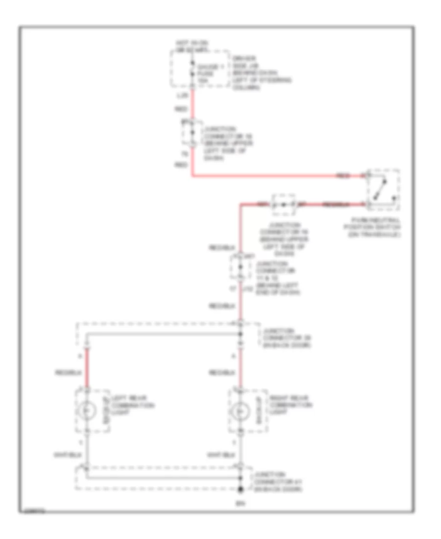
Back-up Lamps Wiring Diagram for Toyota Sienna CE 2007
List of elements for Back-up Lamps Wiring Diagram for Toyota Sienna CE 2007:
- Back-up
- Driver side j/b (behind dash, left of steering column)
- Gauge 1 fuse 10a
- Hot in on or start
- J11
- J12
- Junction connector 11 & 12 (behind left end of dash)
- Junction connector 18 (behind upper left side of dash)
- Junction connector 19 (behind upper left side of dash)
- Junction connector 39 (in back door)
- Junction connector 41 (in back door)
- L26
- Left rear combination light
- Park/neutral position switch (on transaxle)
- Red
- Right rear combination light
Exterior Lamps Wiring Diagram (1 of 2) for Toyota Sienna CE 2007
List of elements for Exterior Lamps Wiring Diagram (1 of 2) for Toyota Sienna CE 2007:
- (at left rear quarterpanel) bm
- (at right "c" pillar) bl
- (behind right side of dash) j/c 28
- (behind upper left side of dash) j/c 18
- Brk relay
- C16
- C21
- Driver side j/b (behind dash, left of steering column)
- Ecu-ig fuse 10a
- Gauge 1 fuse 10a
- High mounted stop light
- Hot at all times
- Hot in on or start
- J/c 15 (behind left end of dash)
- J/c 2 (at left side of engine compt)
- J/c 31 & 32 (behind right side of dash)
- J/c 37 (forward of left rear wheelwell)
- J/c 38 (behind left rear quarterpanel)
- J/c 39 (in back door)
- J/c 41 (in back door)
- J31
- J32
- L17
- L23
- L26
- Left license plate
- Left rear combination light
- Light
- R/b 6 (w/ dynamic laser cruise control) (in engine room j/b)
- R19
- R20
- R21
- R22
- Red
- Right license plate
- Right rear combination light
- Skid control ecu w/ actuator (at left rear of engine compt)
- Stop
- Stop fuse 10a
- Stop light switch (on bracket, above brake pedal)
- Stpo
- Tail
- Turn
- W/ dynamic laser cruise control
- W/o dynamic laser cruise control
Exterior Lamps Wiring Diagram (2 of 2) for Toyota Sienna CE 2007
List of elements for Exterior Lamps Wiring Diagram (2 of 2) for Toyota Sienna CE 2007:
- Alt fuse 140a
- Body ecu (behind left side of dash)
- C11
- C13
- C14
- C17
- C28
- Combi- nation switch
- Combination meter
- Combination switch
- Drive ic
- Driver side j/b (behind dash, left of steering column)
- Ea (at right side of engine compt)
- Ecu-ib fuse 10a
- Ed (at left side of engine compt)
- Ehw
- Engine room j/b (on left side of engine compt)
- Fusible link block (on left side of engine compt, inside engine room j/b)
- Gnd
- H21
- H25
- H26
- Haz
- Haz fuse 15a
- Hazard switch
- Head
- Hot at all times
- Hot in on or start
- Ie (at left kick panel)
- If (behind lower center of dash)
- Ig (at right kick panel)
- J/c 18 (behind upper left side of dash)
- J/c 20 (behind upper left side of dash)
- J/c 21 (w/ memory) (behind upper left center of dash)
- J/c 27 (behind right side of dash)
- J/c 3 & 4 (behind left end of dash)
- L16
- L19
- Left outer rear view mirror
- Left parking/ turn signal light
- Left side marker light
- Left turn ind
- Micro computer
- Off
- P14
- P18
- Park
- Red
- Right outer rear view mirror
- Right parking/ turn signal light
- Right side marker light
- Right turn ind
- Tail
- Tail fuse 10a
- Tail ind (except usa)
- Tail relay
- Trly
- Turn
- Turn signal flasher (behind left side of dash)
- Turn signal light
- W/ memory
- W/o memory
GROUND DISTRIBUTION
Ground Distribution Wiring Diagram (1 of 4) for Toyota Sienna CE 2007
List of elements for Ground Distribution Wiring Diagram (1 of 4) for Toyota Sienna CE 2007:
- (in engine room j/b) r/b 3
- (in engine room j/b) r/b 4
- (in engine room j/b) r/b 6
- (on left side of engine compt) engine room j/b
- (w/ hid) left headlight control ecu
- (w/ hid) right headlight control ecu
- (w/ theft deterrent system) engine hood courtesy switch
- (w/o hid) left headlight (low)
- (w/o hid) right headlight (low)
- A/c compr- essor
- A/f relay
- Brake fluid level warning switch
- Cooling fan ecu
- Defog relay
- Drl 3 relay
- Drl 4 relay
- E10
- Ea (at right side of engine compt)
- Ec (at rear of engine)
- Ed (at left side of engine compt)
- Efi relay
- Engine control module
- Fan relay
- Front window deicer
- Front wiper motor
- Htr relay
- Ig2 relay
- J/c 1 (at left side of engine compt)
- J/c 27 (behind right side of dash)
- Keyless buzzer
- Left front fog light
- Left headlight beam level control actuator
- Left parking light & turn signal light
- Left side marker light
- Right front fog light
- Right headlight beam level control actuator
- Right parking light & turn signal light
- Right side marker light
- Rr a/c relay
- Running light resistor
- Skid control ecu w/ actuator
- St relay
- Washer level sensor
Ground Distribution Wiring Diagram (2 of 4) for Toyota Sienna CE 2007
List of elements for Ground Distribution Wiring Diagram (2 of 4) for Toyota Sienna CE 2007:
- (6 speaker) radio & player
- (w/ rear seat entertainment system) television display
- 10 speaker
- A21
- Air bag sensor assembly
- Air fuel ratio sensor (bank 1 sensor 1) shield
- Air fuel ratio sensor (bank 2 sensor 1) shield
- Bi (at right "b" pillar)
- Bj (in right sliding door)
- Bk (in right sliding door)
- Bl (at right "c" pillar)
- Blower motor controller (rear)
- C13
- Canister pump module
- Combination meter
- Combination switch
- Crankshaft position sensor shield
- Data link connector
- Distance control ecu
- Driver side j/b (behind dash, left of steering column)
- E10
- E11
- Eb (at front of engine)
- Engine control module
- Front passenger's power seat control switch
- Heated oxygen sensor (bank 1 sensor 2) shield
- Heated oxygen sensor (bank 2 sensor 2) shield
- If (behind lower center of dash)
- Ignition coil & igniter 1
- Ignition coil & igniter 2
- Ignition coil & igniter 3
- Ignition coil & igniter 4
- Ignition coil & igniter 5
- Ignition coil & igniter 6
- J/c 13 & 14 (behind left end of dash)
- J/c 20 (behind upper left side of dash)
- J/c 23 (behind upper center of dash)
- J/c 28 (behind right side of dash)
- J/c 42 (w/ vsc) (forward of right wheelwell)
- J/c 48
- J13
- J14
- Knock sensor 1 & 2 shield
- Laser sensor
- Nca
- Occupant classification ecu
- P28
- R15
- Radio & player
- Radio & player w/ display
- Right folding motor
- Right power slide door control motor & clutch
- Right power slide door control switch
- Right power slide door ecu
- Right power slide door lock assembly
- Right rear combination light
- Right seat heater ecu
- Right seat power rear
- Right slide door attachment control
- S10
- S23
- S24
- S25
- Stereo component amplifier
- Telephone microphone shield
- Tire pressure warning ecu
- W/ 6 speaker & w/o rear seat entertainment system
- W/ navigation system
- W/ power seat
- W/ power slide door
- W/ vsc
- W/o 6 speaker & rear seat entertainment system
- W/o navigation system
- W/o power seat
- W/o power side door
- W/o power slide door
- W/o vsc
- Yaw rate sensor
Ground Distribution Wiring Diagram (3 of 4) for Toyota Sienna CE 2007
List of elements for Ground Distribution Wiring Diagram (3 of 4) for Toyota Sienna CE 2007:
- (if equipped) moon roof control ecu
- A/c control assembly
- A21
- Acc relay
- Accessory meter
- Air bag sensor assembly
- Automatic a/c
- Body ecu
- C11
- C12
- Clearance sonar ecu
- Combination switch
- Driver side j/b (behind dash, left of steering column)
- Ie (at left kick panel)
- Ig1 relay
- Inner mirror
- J/c 18 (behind upper left side of dash)
- K17
- Key interlock solenoid & unlock warning
- L16
- Left control outer mirror ecu
- Left front door lock control switch & power window master switch
- Left front door lock motor & door unlock detection switch
- Left mirror heater & remote control mirror
- Left outer rear view mirror
- Left vanity light
- Manual a/c
- Personal light
- Power quarter window
- Pwr relay
- Rear a/c control switch
- Right vanity light
- Satellite switch
- Seat memory switch
- Shift lock control ecu & transmission control switch
- Switch
- Tail relay
- Tire pressure warning reset switch
- Traction control switch
- Transponder key computer
- Turn signal flasher
- W/ driving position memory
- W/ moon roof
- W/o moon roof
Ground Distribution Wiring Diagram (4 of 4) for Toyota Sienna CE 2007
List of elements for Ground Distribution Wiring Diagram (4 of 4) for Toyota Sienna CE 2007:
- (driver's seat lumbar support control) power seat control switch
- (if equipped) left power slide door ecu
- (if equipped) left power slide door lock assembly
- Back door lock assembly
- Back door opener switch
- Bh (at left "b" pillar)
- Blower motor (front)
- Blower motor controller (front)
- Blower resistor
- Blower switch
- Bm (at left rear quarter panel)
- Bn (at left side of back door)
- Combination meter
- Data link connector
- Dome cut relay
- Door lock control receiver
- Driver's power seat control switch
- Driver's seat heater switch
- Front passenger's seat heater switch
- Fuel lid courtesy switch
- Fuel pump
- Gateway ecu
- Hazard switch & rear window defogger switch
- Headlight beam level control switch
- High mounted stop light
- Ig (at right kick panel)
- Interior light
- Inverter relay
- J/c 16 (behind left end of dash)
- J/c 20 (behind upper left side of dash)
- J/c 38 (behind left rear quarter panel)
- J/c 41
- J/c 44 & 45 (w/ power seat) (under left front seat)
- J44
- J45
- Left folding motor
- Left license plate light
- Left power slide door control switch
- Left power slide door ecu
- Left rear combination light
- Left seat heater ecu
- Left seat power rear 2
- Left slide door attachment control
- Main switch
- P14
- P25
- P26
- P58
- Position control switch ecu
- Power back door ecu
- Power outlet (rear)
- Power outlet 1
- Power outlet 2
- R32
- Rear window defogger
- Remote control mirror switch
- Right control outer mirror ecu
- Right front door lock control switch
- Right front door lock motor & right front door unlock detection switch
- Right license plate light
- Right mirror heater & remote control mirror
- Right outer rear view mirror
- Right rear combination light
- S20
- S21
- S22
- Slide door closer ecu
- Steering sensor
- Switch
- Voltage inverter
- W/ automatic a/c
- W/ driving position memory
- W/ manual a/c
- W/ power seat(driver's seat)
- W/ power slide door
- W/o driving position memory
- W/o power slide door
HEADLIGHTS
Headlights Wiring Diagram, with DRL (1 of 2) for Toyota Sienna CE 2007
List of elements for Headlights Wiring Diagram, with DRL (1 of 2) for Toyota Sienna CE 2007:
- (behind left end of dash) j/c 11 & 12
- (behind left end of dash) j/c 5 & 6
- Acc
- Auto
- Automatic light control sensor (on top left side of dash)
- Becu
- Body ecu
- C10
- C11
- C23
- C24
- Cltb
- Clte
- Clts
- Combination meter
- Combination switch
- Computer data lines system
- Dcty
- Dimmer switch
- Drive ic
- Driver side j/b (behind dash, left of steering column)
- Drl
- Ecu acc fuse 7.5a
- Ecu-b fuse 10a
- Ecu-ig fuse 10a
- Engine room j/b (on left side of engine compt)
- Ffgo
- Ffog
- Flash
- Fog light switch
- Gauge 2 fuse 7.5a
- Gnd1
- Gnd2
- H25
- Head
- Head ind (usa)
- High
- High beam indicator
- Hot at all times
- Hot in acc or on
- Hot in on or start
- Hrly
- Ie (at left kick panel)
- If (behind lower center of dash)
- J/c 18 (behind upper left side of dash)
- J/c 19 (behind upper left side of dash)
- J/c 20 (behind upper left side of dash)
- J11
- J12
- K10
- K17
- L16
- Left front door courtesy switch (at left "b" pillar)
- Light control switch off
- Low
- Micro computer
- Mpx1
- Mpx2
- Off
- Parking brake switch (on parking brake lever)
- Pkb
- Red
- Tail
Headlights Wiring Diagram, with DRL (2 of 2) for Toyota Sienna CE 2007
List of elements for Headlights Wiring Diagram, with DRL (2 of 2) for Toyota Sienna CE 2007:
- (behind right headlight)
- (in engine room j/b) r/b 3
- (in engine room j/b) r/b 4
- (on left side of engine compt) engine room j/b
- C11
- C12
- Control ecu
- Driver side j/b (behind dash, left of steering column)
- Drl 2 relay
- Drl 3 relay
- Drl 4 relay
- Drl fuse 20a
- Ea (at right side of engine compt)
- Ecu control light
- Ed (at left side of engine compt)
- Fog fuse 15a
- Fog relay
- H28
- Head relay
- Hot at all times
- J/c 1 (at left side of engine compt)
- J/c 2 (at left side of engine compt)
- J/c 27 (behind right side of dash)
- Left front fog light
- Left headlight (high)
- Left headlight (low)
- Left headlight control ecu (behind left headlight)
- Lh h-lp fuse 10a
- Light
- Ll h-lp fuse 15a
- Low (hid)
- Main fuse 30a
- Red
- Rh h-lp fuse 10a
- Right front fog light
- Right headlight (high)
- Right headlight (low)
- Right headlight control ecu
- Rl h-lp fuse 15a
- Running light resistor (right side of engine compt)
- Short pin
- W/ hid
- W/o hid
Headlights Wiring Diagram, without DRL (1 of 2) for Toyota Sienna CE 2007
List of elements for Headlights Wiring Diagram, without DRL (1 of 2) for Toyota Sienna CE 2007:
- (behind left end of dash) j/c 11 & 12
- Acc
- Becu
- Body ecu
- C10
- C11
- C24
- Combination meter
- Combination switch
- Computer data lines system
- Dcty
- Dimmer switch
- Drive ic
- Driver side j/b (behind dash, left of steering column)
- Ecu acc fuse 7.5a
- Ecu-ig fuse 10a
- Ffgo
- Ffog
- Flash
- Fog light switch
- Gauge 2 fuse 7.5a
- Gnd1
- Gnd2
- H25
- Head
- Head ind (usa)
- High
- High beam indicator
- Hot in acc or on
- Hot in on or start
- Hrly
- Ie (at left kick panel)
- If (behind lower center of dash)
- J/c 18 (behind upper left side of dash)
- J/c 19 (behind upper left side of dash)
- J11
- J12
- K17
- L16
- Left front door courtesy switch (at left "b" pillar)
- Light control switch off
- Low
- Micro computer
- Mpx1
- Mpx2
- Off
- Tail
Headlights Wiring Diagram, without DRL (2 of 2) for Toyota Sienna CE 2007
List of elements for Headlights Wiring Diagram, without DRL (2 of 2) for Toyota Sienna CE 2007:
- C11
- C12
- Control ecu
- Driver side j/b (behind dash, left of steering column)
- Ea (at right side of engine compt)
- Ecu
- Ecu-b fuse 10a
- Ed (at left side of engine compt)
- Engine room j/b (on left side of engine compt)
- Fog fuse 15a
- Fog relay
- H28
- Head relay
- Hot at all times
- J/c 1 (at left side of engine compt)
- J/c 2 (at left side of engine compt)
- J/c 27 (behind right side of dash)
- Left front fog light
- Left headlight (low)
- Left headlight control ecu (behind left headlight)
- Light
- Light control
- Ll h-lp fuse 15a
- Low (hid)
- Main fuse 30a
- Red
- Right front fog light
- Right headlight (low)
- Right headlight control ecu (behind right headlight)
- Rl h-lp fuse 15a
- W/ hid
- W/o hid
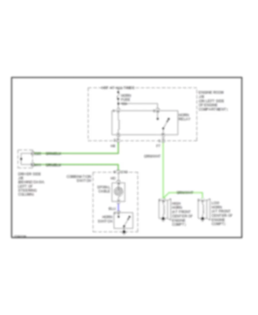
HORN
Horn Wiring Diagram for Toyota Sienna CE 2007
List of elements for Horn Wiring Diagram for Toyota Sienna CE 2007:
- C13
- C25
- Combination switch
- Driver side j/b (behind dash, left of steering column)
- Engine room j/b (on left side of engine compartment)
- H11
- High horn (at front center of engine compt)
- Horn fuse 10a
- Horn relay
- Horn switch
- Hot at all times
- Low horn (at front center of engine compt)
- Spiral cable
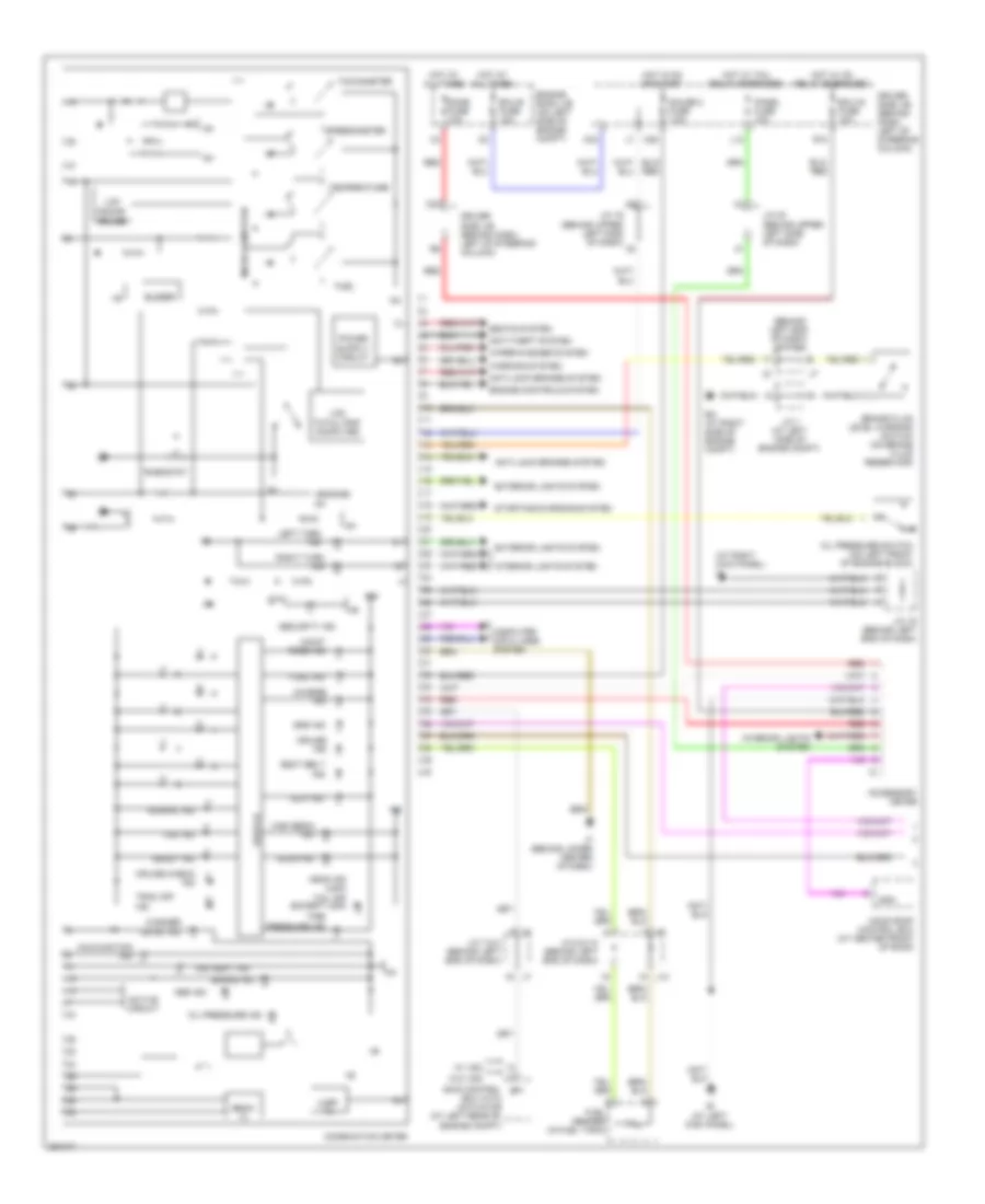
INSTRUMENT CLUSTER
Instrument Cluster Wiring Diagram (1 of 2) for Toyota Sienna CE 2007
List of elements for Instrument Cluster Wiring Diagram (1 of 2) for Toyota Sienna CE 2007:
- (at right kick panel) ig
- (behind left end of dash) j/c 7 & 8
- +b(dome) ig+
- 3rd seat ind
- Abs ind
- Accessory meter
- Active circuit
- Anti-lock brakes system
- Anti-theft system
- Bean ic
- Brake fluid level warning switch (on brake fluid reservoir)
- Brake ind
- Buzzer
- C24
- C27
- Charge ind
- Combination meter
- Computer data lines system
- Cruise check ind
- Cruise ind
- Dome fuse 10a
- Door ind
- Drive ic
- Driver side j/b (behind dash, left of steering column)
- Ea (at right side of engine compt)
- Ecu with actuator (at left rear of engine compt)
- Ecu-b fuse 10a
- Ecu-ig fuse 10a
- Engine controls system
- Engine room j/b (on left side of engine compt)
- Exterior lights system
- Fuel
- Fuel ind
- Fuel sender (in fuel tank)
- Gauge 2 fuse 7.5a
- H25
- Head ind (usa) tail ind (except usa)
- High beam ind
- Hot at all times
- Hot in on or start
- Hot w/ ig1 relay energized
- Hot w/ tail relay energized
- Ie (at left kick panel)
- If (behind lower center of dash)
- Ig+
- Interior lights system
- J/c 1 (at left side of engine compt)
- J/c 16 (behind left end of dash)
- J/c 19 (behind upper left side of dash)
- J/c 20 (behind upper left side of dash)
- J/c 7 & 8 (behind left end of dash)
- J/c 9 & 10 (behind left end of dash)
- J10
- L12
- Lcd
- Lcd total/trip computer
- Left turn ind
- Maint reqd ind
- Malfunction ind
- Micro computer
- Moon roof control ecu (at center front of roof)
- Normal ind
- Oil pressure ind
- Oil pressure switch (on left front of engine block)
- Panel fuse 10a
- R10
- Radar cruise
- Ready ind
- Red
- Rheostat
- Right turn ind
- Seat belt ind
- Seats system
- Security ind
- Skid control sp1
- Slip ind
- Spd
- Speedometer
- Srs ind
- Starting/charging system
- Tachometer
- Temperature
- Tire pressure ind
- Trac off ind
- Uart tx
- Vsc ind
- W/ vsc
- W/o vsc
- Warning system
- Washer level ind
- Wiper/washer system
Instrument Cluster Wiring Diagram (2 of 2) for Toyota Sienna CE 2007
List of elements for Instrument Cluster Wiring Diagram (2 of 2) for Toyota Sienna CE 2007:
- (at left "b" pillar) left front door courtesy switch
- (behind left end of dash) j/c 11 & 12
- (behind right side of dash) j/c 33 & 34
- (behind upper left side of dash)
- (behind upper left side of dash) j/c 18
- Altb
- Body ecu
- C30
- Canh
- Canl
- Clearance sonar ecu (behind center of dash)
- Computer data
- Computer data lines system
- Dcty
- Door 2 fuse 25a
- Driver side j/b (behind dash, left of steering column)
- Engine control module (behind right side of dash)
- Engine room j/b (on left side of engine compt)
- Hot at all times
- J/c 19
- J/c 20 (behind upper left side of dash)
- J/c 5 & 6 (behind left end of dash)
- J11
- J12
- J33
- J34
- K10
- Lcty
- Left slide door courtesy switch
- Lines system
- Mpx1
- Mpx2
- P19
- Parking brake switch (on parking brake lever)
- Pcty
- Pkb
- R12
- Radio & player (6 speaker w/ rse)
- Radio & player (6 speaker w/o rse)
- Radio & player w/ display (w/ navigation)
- Rcty
- Right front door courtesy switch (at right "b" pillar)
- Right slide door courtesy switch
- Spd
- Stereo component amplifier (10 speaker w/o navigation)
- Tach
INTERIOR LIGHTS
Courtesy Lamps Wiring Diagram (1 of 2) for Toyota Sienna CE 2007
List of elements for Courtesy Lamps Wiring Diagram (1 of 2) for Toyota Sienna CE 2007:
- (at left kick panel) ie
- (at right kick panel) ig
- (behind left end of dash) j/c 11 & 12
- (behind right side of dash) j/c 33 & 34
- (behind upper left side of dash) j/c 20
- (w/o memory) left front door courtesy light
- Acc
- B7 mpx1 lcty dcyl
- Back door lock assembly (w/o power back door) (at lower left center of back door)
- Bcty
- Becu
- Body ecu
- C16
- C24
- C27
- Combination meter
- Computer data lines system
- Ctyb
- Ctyo
- Cyl
- D14
- D15
- Dome fuse 10a
- Door indicator
- Door lock control receiver (behind upper center of dash)
- Driver side j/b (behind dash, left of steering column)
- Ecu acc fuse 7.5a
- Ecu-b fuse 10a
- Ecu-ig fuse 10a
- Engine room j/b (on left side of engine compt)
- Gauge2 fuse 7.5a
- Gnd
- Gnd2 gnd1
- H25
- H30
- Hot at all times
- Hot in acc or on
- Hot in on or start
- Ie (at left kick panel)
- If (behind lower center of dash)
- Ile
- J/c 11 & 12 (behind left end of dash)
- J/c 13 & 14 (behind left end of dash)
- J/c 15 (behind left end of dash)
- J/c 18 (behind upper left side of dash)
- J/c 19 (behind upper left side of dash)
- J/c 35 & 36 (behind right side of dash)
- J/c 37 (forward of left rear wheelwell)
- J/c 41 (in back door)
- J/c 7 & 8 (behind left end of dash)
- J11
- J12
- J13
- J14
- J33
- J34
- J35
- J36
- K17
- L13
- L16
- Left front door courtesy light (w/ memory)
- Left front door courtesy switch (at left "b" pillar)
- Left outer mirror control ecu
- Left outer rear view mirror (w/ memory)
- Left power rear 2 seat switch (w/ power rear 2 seat w/ stowing function)
- Left slide door courtesy switch
- Micro computer
- Mpx1
- O10
- P16
- P19
- Pcty
- Pcyl
- Power back door ecu (behind left rear quarterpanel)
- Prg
- Rcut mpx2
- Rda
- Rda prg rcty dcty
- Red
- Right front door courtesy light (w/o memory)
- Right front door courtesy switch (at right "b" pillar)
- Right power rear 2 seat switch (w/ power rear 2 seat w/ stowing function)
- Right slide door courtesy switch
- Stop fuse 10a
- W/ power back door
Courtesy Lamps Wiring Diagram (2 of 2) for Toyota Sienna CE 2007
List of elements for Courtesy Lamps Wiring Diagram (2 of 2) for Toyota Sienna CE 2007:
- Ctyb
- Cyl
- Dome cut relay (behind left side of dash)
- Door
- I13
- I14
- Ig (at right kick panel)
- Ignition key cylinder light
- Interior light switch
- J/c 11 & 12 (behind left end of dash)
- J/c 16 (behind left end of dash)
- J/c 19 (behind upper left side of dash)
- J/c 20 (behind upper left side of dash)
- J/c 31 & 32 (behind right side of dash)
- J/c 37 (forward of left rear wheelwell)
- J11
- J12
- J31
- J32
- Left interior light 1
- Left interior light 2
- Left slide door courtesy light
- Left vanity light
- Luggage compartment light
- Mpx1
- O11
- O12
- Off
- Personal light
- Red
- Right front door courtesy light (w/ memory)
- Right interior light 1
- Right interior light 2
- Right outer mirror control ecu
- Right outer rear view mirror (w/ memory)
- Right slide door courtesy light
- Right vanity light
- W/ immobilizer system
- W/ memory
- W/o immobilizer system
Instrument Illumination Wiring Diagram for Toyota Sienna CE 2007
List of elements for Instrument Illumination Wiring Diagram for Toyota Sienna CE 2007:
- (at left kick panel) ie
- (behind lower center of dash) if
- (behind upper left side of dash) j/c 19
- (w/ navigation) radio & player w/ display
- 10 speaker
- 6 speaker
- 6 speaker w/o rse
- A/c control assembly
- A/t shift lever illumination
- Accessory meter
- Automatic a/c
- Back door main switch
- Body ecu
- C11
- C13
- C24
- Combination meter
- Combination switch
- Driver side j/b (behind dash, left of steering column)
- Eau
- Ecu-b fuse 10a
- Engine room j/b (on left side of engine compt)
- Except 6 speaker w/o rse
- Gauge2 fuse 7.5a
- H25
- Hazard switch rear window defogger switch
- Head
- Headlight beam level control switch
- Heater switch (driver's seat)
- Heater switch (front passenger's seat)
- Hot at all times
- Hot in on or start
- Ie (at left kick panel)
- If (behind lower center of dash)
- Ig (at right kick panel)
- Il+2
- Ill+
- Ill-
- Interior light switch
- J/c 13 & 14 (behind left end of dash)
- J/c 16 (behind left end of dash)
- J/c 19 (behind upper left side of dash)
- J/c 20 (behind upper left side of dash)
- J/c 23 (behind upper center of dash)
- J/c 35 & 36 (behind right side of dash)
- J13
- J14
- J35
- J36
- L12
- L16
- Left power slide door control switch
- Left steering pad switch
- Main switch
- Manual a/c
- Micro computer
- Off
- Panel fuse 10a
- Power
- Power quarter window switch
- Power slide door main switch
- R13
- R15
- Radio & player
- Radio & player (w/o navigation)
- Rear a/c control switch
- Right power slide door control switch
- Right steering pad switch
- Satellite switch
- Seat
- Spiral cable
- Tail
- Tail relay
- Traction control switch (w/vsc)
- Trly
- W/ navigation
- W/o navigation
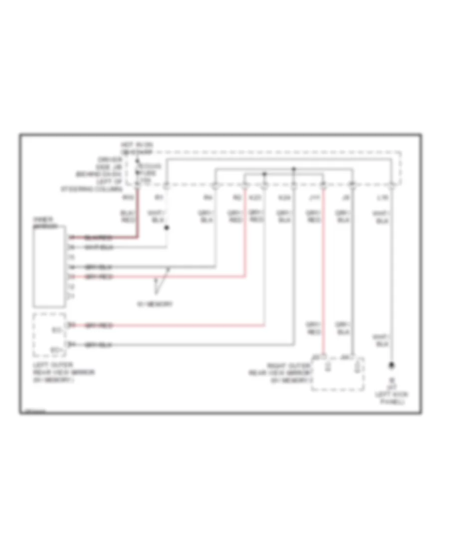
MEMORY SYSTEMS
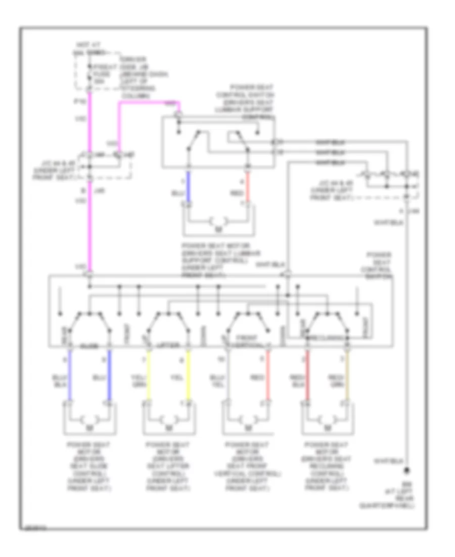
Memory Systems Wiring Diagram (1 of 2) for Toyota Sienna CE 2007
List of elements for Memory Systems Wiring Diagram (1 of 2) for Toyota Sienna CE 2007:
- (under left front seat) driver seat slide control power seat motor
- Bdr
- Body ecu
- C24
- Computer data lines system
- Cpub
- Ctyb
- Cyl
- De2
- Dm+r
- Dmhr
- Dmvr
- Down
- Driver side j/b (behind dash, left of steering column)
- Dvc
- Ecu acc fuse 7.5a
- Ecu-b fuse 10a
- Ecu-ig fuse 10a
- Engine room j/b (on left side of engine compt)
- Gnd
- Hot at all times
- Hot in acc or on
- Hot in on or start
- Hssr
- Ie (at left kick panel)
- Ig (at right kick panel)
- Interior lights system
- J/c 18 (behind upper left side of dash)
- J/c 20 (behind upper left side of dash)
- K21
- K34
- L23
- Left
- Left outer mirror control ecu (in left front door)
- Mirb
- Mire
- Mirs
- Mpx1
- Mpx2
- O10
- P/seat fuse 30a
- P/w fuse 25a
- P10
- Pnk
- Red
- Remote control mirror switch
- Retraction
- Return
- Right
- Seat memory switch
- Sel1
- Sig
- Vssr
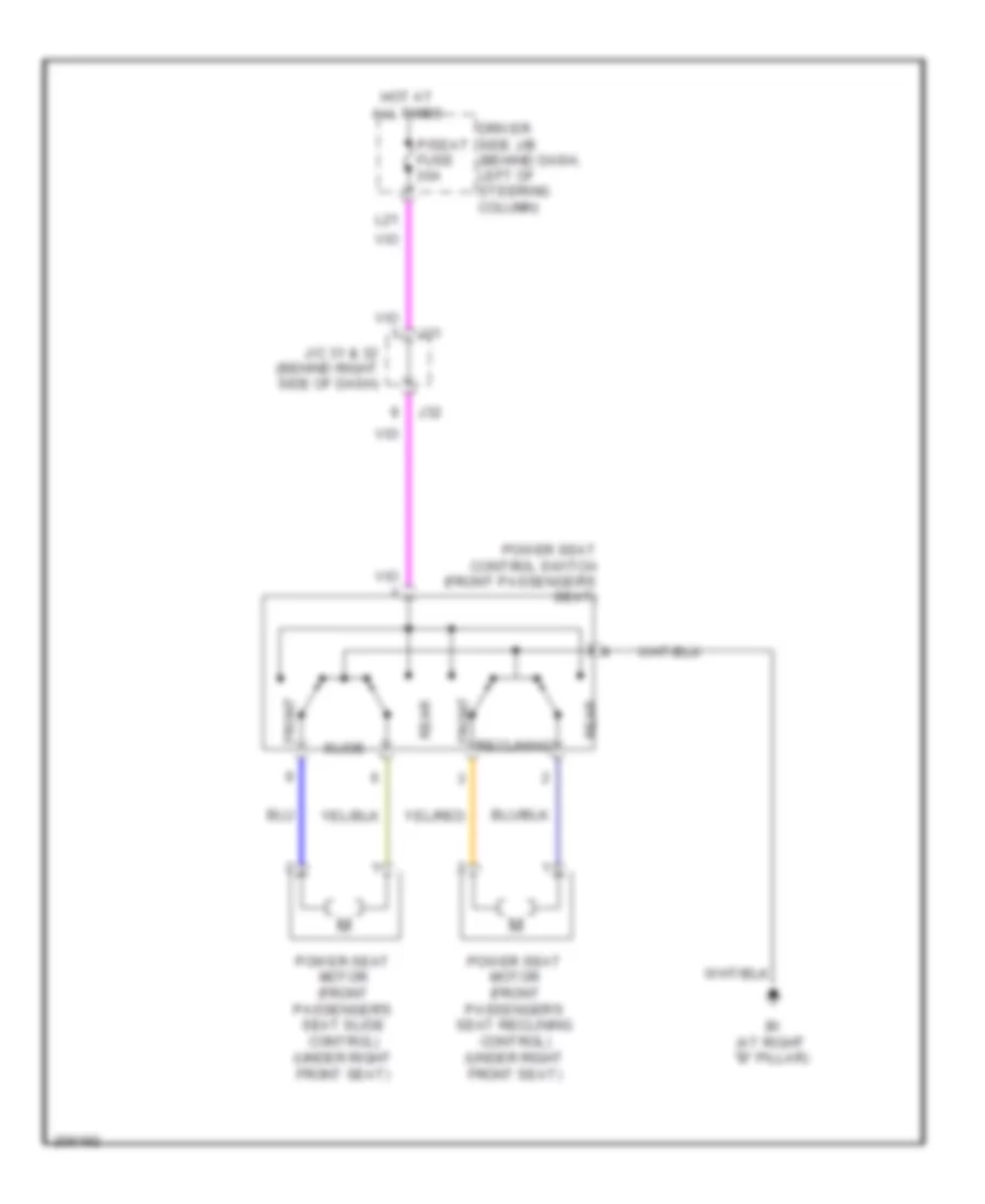
Memory Systems Wiring Diagram (2 of 2) for Toyota Sienna CE 2007
List of elements for Memory Systems Wiring Diagram (2 of 2) for Toyota Sienna CE 2007:
- (behind left end of dash) j/c 13 & 14
- (behind upper left side of dash) junction connector 19
- (forward of left rear wheelwell) j/c 37
- (under left front seat) driver seat front vertical control power seat motor
- (under left front seat) driver seat lifter control power seat motor
- (under left front seat) driver seat reclining control power seat motor
- (under left front seat) junction connector 44 & 45
- Bdr
- Bh (at left "b" pillar)
- Computer data lines system
- Cpub
- Ctrl circuit
- Ctyb
- Cyl
- Driver seat lumbar support control power seat control motor (under left front seat)
- Driver seat lumbar support control power seat control switch
- Frv+
- Frv-
- Gnd
- Hssr
- Ig (at right kick panel)
- Interior lights system
- J/c 44 & 45 (under left front seat)
- J13
- J14
- J44
- J45
- Left outer rear view mirror
- Lft+
- Lft-
- Mpx1
- O11
- O12
- P58
- P59
- Pe2
- Pm+r
- Pmhr
- Pmvr
- Pnk
- Position control ecu & switch
- Pvc
- Rcl+
- Rcl-
- Red
- Right outer mirror control ecu (in right front door)
- Right outer rear view mirror
- Sig
- Sld+
- Sld-
- Sysb
- Vssr
NAVIGATION
Navigation Wiring Diagram, Rear View Monitor & Audio System (1 of 3) for Toyota Sienna CE 2007
List of elements for Navigation Wiring Diagram, Rear View Monitor & Audio System (1 of 3) for Toyota Sienna CE 2007:
- (at left side of back door) television camera
- (behind dash, left of steering column) driver side j/b
- (behind left end of dash) j/c 5 & 6
- (behind left end of dash) j/c 7 & 8
- (in roof console) telephone microphone
- Acc
- Adpg
- Alo
- Aro
- Asgn
- Auxo
- Ca+
- Cdl+
- Cdl-
- Cdr+
- Cdr-
- Cgnd
- Csld
- Ecu-b fuse 10a
- Engine room j/b (on left side of engine compt)
- Gnd
- Hot at all times
- Ivo+
- Ivo-
- K10
- L1+
- Macc
- Mi1+
- Mic+
- Mic-
- Mute
- Nca
- Ntsc
- Parking brake switch (on parking brake lever)
- Pkb
- Pnk
- R1+
- R10
- R12
- R13
- R14
- R16
- Rad 1 fuse 20a
- Rad 3 fuse 30a
- Radio & player w/ display
- Red
- Rev
- Sgn1
- Sgnd
- Sld
- Sld1
- Sld9
- Spd
- Stereo jack adapter
- Sw1
- Sw2
- Swg
- T14
- Television display (w/ rear seat entertainment system)
- Tsw-
- Tx+
- Tx-
- Txm+
- Txm-
- Va-
- Val+
- Var+
- Vv+
- Vv-
Navigation Wiring Diagram, Rear View Monitor & Audio System (2 of 3) for Toyota Sienna CE 2007
List of elements for Navigation Wiring Diagram, Rear View Monitor & Audio System (2 of 3) for Toyota Sienna CE 2007:
- (behind upper center of dash) j/c 23
- (behind upper center of dash) j/c 24
- (w/ vsc)
- (w/o vsc)
- Au1
- Au2
- Auxl
- Auxr
- C13
- C24
- Combination meter
- Combination switch
- Driver side j/b (behind dash, left of steering column)
- Eau
- End of dash)
- Gauge 1 fuse 10a
- Gauge 2 fuse 7.5a
- H25
- Hot at all times
- Hot in acc or on
- Hot in on or start
- If (behind lower center of dash)
- Ig+
- J/c 11 & 12 (behind left j11
- J/c 18 (behind upper left side of dash)
- J/c 19 (behind upper left side of dash)
- J/c 20 (behind upper left side of dash)
- J/c 7 & 8 (behind left end of dash)
- J12
- L24
- L26
- Left rear speaker
- Left steering pad switch
- Micro computer
- Mode
- Nca
- Ntsc
- Off hook
- On hook
- Park/ neutral position switch (on transaxle)
- Pnk
- R/b 3 (in engine room j/b)
- Rad2 fuse 7.5a
- Red
- Right steering pad switch
- Rse fuse 7.5a
- Seek+
- Seek-
- Sgnd
- Skid control ecu w/ actuator (at left rear of engine compt)
- Sld
- Sp1
- Speedometer
- Spiral cable
- Video terminal
- Voice
- Vol+
- Vol-
Navigation Wiring Diagram, Rear View Monitor & Audio System (3 of 3) for Toyota Sienna CE 2007
List of elements for Navigation Wiring Diagram, Rear View Monitor & Audio System (3 of 3) for Toyota Sienna CE 2007:
- (behind upper center of dash) j/c 22
- (behind upper center of dash) j/c 23
- Acc
- Ant
- Ant +b
- Atx+
- Atx-
- B2+
- Center speaker
- Ctr+
- Ctr-
- Fl+
- Fl-
- Fr+
- Fr-
- Glass antenna amplifier (behind right side of dash)
- Gnd
- Gnd2
- If (behind lower center of dash)
- Ill+
- Ill-
- Int+
- Int-
- Interior lights system
- J/c 35 & 36 (behind right j35
- J36
- Left front door speaker
- Left front tweeter
- Left rear tweeter
- Mute
- Nca
- Pnk
- R15
- Radio & player w/ display
- Red
- Right front door speaker
- Right front tweeter
- Right rear speaker
- Right rear tweeter
- Rl+
- Rl-
- Rr+
- Rr-
- S10
- S11
- Side of dash)
- Sld
- Spd
- Stereo component amplifier (behind right side of dash)
- Sur+
- Sur-
- Tx+
- Tx-
- Wf1+
- Wf1-
- Wf2+
- Wf2-
- Woofer
Parking Assistant Wiring Diagram for Toyota Sienna CE 2007
List of elements for Parking Assistant Wiring Diagram for Toyota Sienna CE 2007:
- (at left kick panel) ie
- (automatic a/c)
- (behind upper left side of dash)
- (behind upper left side of dash) j/c 18
- (manual a/c)
- 6 sensor
- A/c control assembly
- A10
- A11
- Automatic a/c
- Bbz
- Buzzer
- C24
- Cbz
- Clearance sonar buzzer (6 sensor) (behind left center of dash)
- Clearance sonar ecu (behind center of dash)
- Combination meter
- Driver side j/b (behind dash, left of steering column)
- Ecu-b fuse 10a
- Ecu-ig fuse 10a
- Engine room j/b (on left side of engine compt)
- Gauge 1 fuse 10a
- Gauge 2 fuse 7.5a
- H25
- Hot at all times
- Hot in on or start
- Hot w/ ig1 relay energized
- If (behind lower center of dash)
- Ig+
- J/c 11 & 12 (behind left end of dash)
- J/c 18 (6 sensor) (behind upper left side of dash)
- J/c 18 (behind upper left side of dash)
- J/c 19
- J/c 19 (behind upper left side of dash)
- J/c 20 (behind upper left side of dash)
- J/c 47
- J/c 5 & 6 (behind left end of dash)
- J/c 7 & 8 (behind left end of dash)
- J11
- J12
- L23
- L26
- Manual a/c
- Micro computer
- Park/neutral position switch (on transaxle)
- Pnk
- Red
- Skid control ecu w/ actuator (at left rear of engine compt)
- Sp1
- Spd
- Speedometer
- Ultrasonic sensor (left front) (6 sensor) (behind left end of front bumper)
- Ultrasonic sensor (left rear center) (behind left center of rear bumper)
- Ultrasonic sensor (left rear) (behind left end 0f rear bumper)
- Ultrasonic sensor (right front) (6 sensor) (behind right end of front bumper)
- Ultrasonic sensor (right rear center) (behind right center of rear bumper)
- Ultrasonic sensor (right rear) (behind right end 0f rear bumper)
- W/ vsc
- W/o vsc
POWER DISTRIBUTION
Power Distribution Wiring Diagram (1 of 3) for Toyota Sienna CE 2007
List of elements for Power Distribution Wiring Diagram (1 of 3) for Toyota Sienna CE 2007:
- (behind dash, left of steering column) driver side j/b
- (behind upper left side of dash)
- (on left side of engine compt, inside engine room j/b) fusible link block
- Abs 1 fuse 50a
- Abs 2 fuse 30a
- Acc
- Acc relay
- Air conditioning & defogger systems
- Air conditioning & mirrors systems
- Air conditioning system
- Air conditioning, defogger & cooling fans systems
- Alt fuse 140a
- Am1 fuse 7.5a
- Anti-lock
- Anti-lock brakes system
- Automatic a/c
- Battery
- Bh (at left "b" pillar)
- Body ecu
- Brakes system
- Cig fuse 15a
- Cooling fans & air conditioning systems
- Cruise control system
- Def fuse 40a
- Defogger system
- Ecu acc fuse 7.5a
- Ecu-ig fuse 10a
- Exterior lights system
- F10
- F11
- F12
- F13
- F14
- F21
- Fan fuse 50a
- From ig1 relay (diagram 1 of 3)
- From ignition switch (diagram 2 of 3)
- Front power outlet 1
- Front power outlet 2
- Garage door opener, interior lights & instrument cluster systems
- Gauge1 fuse 10a
- H29
- Htr fuse 10a
- Htr fuse 50a
- Ie (at left kick panel)
- Ig (at right kick panel)
- Ig1 relay
- Ign
- Instrument cluster, garage door opener, mirrors & power tops systems
- Interior lights system
- J/c 18
- K18 pnk
- L-psd fuse 30a
- L23
- L26 red
- L8 pnk
- Manual a/c
- Memory systems
- Navigation & sound systems
- Navigation system
- Panel fuse 10a
- Pbd fuse 30a
- Pnk
- Power windows system
- Pwr outlet fuse 15a
- Pwr relay
- R-psd fuse 30a
- R/b 3 (diagram 3 of 3)
- Rad 2 fuse 7.5a
- Rear power outlet
- Red
- Relay
- Rr a/c fuse 40a
- Rr wip fuse 15a
- Rr2 seat fuse 50a
- S-htr fuse 15a
- Seats
- Seats system
- Sft fuse 5a
- Shift interlock system
- Shift interlock systems
- St fuse 30a
- Starting/ charging system
- Starting/charging, anti-lock brakes, exterior lights, transmissions, cruise control, trunk, tailgate, fuel doors, navigation, sound & engine controls systems
- System
- Tail
- Tail fuse 10a
- To acc relay (diagram 1 of 3)
- To driver side j/b (diagram 2 of 3)
- To engine room j/b (diagram 3 of 3)
- To ignition switch (diagram 2 of 3)
- To main switch (diagram 2 of 3)
- Trunk, tailgate, fuel doors
- Trunk, tailgate, fuel doors system
- Wip fuse 30a
- Wiper/washer system
- Wsh fuse 20a
Power Distribution Wiring Diagram (2 of 3) for Toyota Sienna CE 2007
List of elements for Power Distribution Wiring Diagram (2 of 3) for Toyota Sienna CE 2007:
- (behind left end of dash) junction connector 11 & 12
- Ac inv fuse 15a
- Ac1
- Ac2
- Acc
- Acc cut relay (left side of dash)
- Am1
- Am2
- Bh (at left "b" pillar)
- C16
- Computer data lines system
- Control module
- Defogger system
- Driver side j/b (behind dash, left of steering column)
- Engine controls, exterior lights, anti-lock brakes, cruise control, interior lights, shift interlock & transmissions systems
- Engine els
- Fog fuse 15a
- Fog relay
- Fr def fuse 15a
- From driver h
- From driver side j/b (diagram 1 of 3)
- From engine room j/b (diagram 3 of 3)
- From fusible link block (diagram 1 of 3)
- From junction connector j18 (diagram 1 of 3)
- Fuse box (behind lower right side of dash)
- Fuse box 2 (right side of dash)
- Ig (at right kick panel)
- Ig1
- Ig2
- Ignition switch
- Inverter relay (behind upper left side of dash)
- J11
- J12
- Junction connector 20 (behind upper left side of dash)
- Junction connector 3 & 4 (behind left end of dash)
- K12
- K16
- K21
- K33
- K34
- L21
- Lock
- Main switch
- Memory systems
- Obd fuse 7.5a
- Off
- P/seat fuse 30a
- P/w fuse 25a
- P10
- Pnk
- Power outlet 1
- Power outlet 2
- Power tops system
- Power windows & memory systems
- R12
- S/roof fuse 25a
- Seats system
- Sft fuse 5a
- Shift interlock system
- Side j/b (diagram 1 of 3)
- St fuse 7.5a
- St2
- Start
- Starting/ charging, engine controls & transmissions systems
- Stop fuse 10a
- To driver side j/b (diagram 1 of 3)
- To driver side j/b (diagram 3 of 3)
- Voltage inverter (above left rear wheelwell)
Power Distribution Wiring Diagram (3 of 3) for Toyota Sienna CE 2007
List of elements for Power Distribution Wiring Diagram (3 of 3) for Toyota Sienna CE 2007:
- (behind dash, left of steering column) driver side j/b
- (on left side of engine compt) engine room j/b
- A/f fuse 25a
- Air conditioning & defogger systems
- Air conditioning, defogger & cooling fans systems
- Alt-s fuse 7.5a
- Am2 fuse 30a
- Body computer, anti-theft & door locks systems
- Cruise control, anti-theft, transmissions &
- Cruise control, engine controls, transmissions & systems
- Cruise control, transmissions & engine controls systems
- Dome fuse 10a
- Door 2 fuse 25a
- Driver side j/b (behind dash, left of steering column)
- Drl fuse 20a
- Ecu-b fuse 10a
- Efi 1 fuse 20a
- Efi relay
- Engine controls system
- Engine controls systems
- Engine room j/b (on left side of engine compt)
- Etcs fuse 10a
- Exterior lights system
- From driver side j/b (diagram 1 of 3)
- From engine k room j/b (diagram 3 of 3)
- From fusible link block (diagram 1 of 3)
- From ignition switch (diagram 2 of 3)
- Gauge 2 fuse 7.5a
- H18 red
- H27
- H3 red
- Haz fuse 15a
- Head relay
- Headlights system
- Horn fuse 10a
- Horn relay
- Htr fuse 10a
- Ig 2 fuse 7.5a
- Ign fuse 7.5a
- Instrument cluster & trunk, tailgate, fuel doors systems
- Interior lights, garage door opener,
- L-rr2 seat fuse 30a
- Main fuse 30a
- Navigation & sound systems
- Pin
- R-rr2 seat fuse 30a
- R/b 3 (in engine room j/b)
- Rad 1 fuse 20a
- Rad 3 fuse 30a
- Red
- Rr wip fuse 15a
- Seats system
- Short
- Sound & navigation systems
- Starting/ charging system
- To engine room j/b (diagram 3 of 3)
- To ignition switch (diagram 2 of 3)
- Wip fuse 30a
- Wiper/washer system
- Wsh fuse 20a
POWER DOOR LOCKS
Power Door Locks Wiring Diagram (1 of 2) for Toyota Sienna CE 2007
List of elements for Power Door Locks Wiring Diagram (1 of 2) for Toyota Sienna CE 2007:
- (at left kick panel) ie
- (at right side of engine compt) ea
- Acc
- Act+
- Act-
- Actd
- Altb
- Bcty
- Becu
- Body ecu (behind left side of dash)
- Buzzer
- Bzr
- C24
- C25
- C30
- Dcty
- Door 2 fuse 25a
- Door lock control receiver (behind upper center of dash)
- Driver side j/b (behind dash, left of steering column)
- Ecu acc fuse 7.5a
- Ecu-b fuse 10a
- Ecu-ig fuse 10a
- Ehw
- Engine hood courtesy switch (center front of engine compt)
- Engine room j/b (on left side of engine compt)
- Gauge 2 fuse 7.5a
- Gnd
- Gnd2
- H25
- Haz
- Hcty
- Horn
- Horns system
- Hot at all times
- Hot in acc or on
- Hot in on or start
- Ie (at left kick panel)
- Ig (at right kick panel)
- Ind
- J/c 1 (at left side of engine compt)
- J/c 11 & 12 (behind left end of dash)
- J/c 18 (behind upper left side of dash)
- J/c 19 (behind upper left side of dash)
- J/c 20 (behind upper left side of dash)
- J/c 3 & 4 (behind left end of dash)
- J11
- J12
- K17
- K22
- K25
- K26
- Keyless buzzer (behind left front corner lamp)
- Ksw
- Lcty
- Left front door courtesy switch (at left "b" pillar)
- Left slide door courtesy switch
- Lock
- Lock left front door lock control switch
- Lswd
- Lswl
- Lswp
- Lswr
- P17
- P19
- Pcty
- Prg
- Rcty
- Rda
- Right front door lock control switch
- Theft deterrent horn (on right rear of engine compt)
- Tr+
- Turn signal flasher (behind left side of dash)
- Ul1
- Ul2
- Ul3
- Unlock
- Unlock warning switch (on upper steering column)
Power Door Locks Wiring Diagram (2 of 2) for Toyota Sienna CE 2007
List of elements for Power Door Locks Wiring Diagram (2 of 2) for Toyota Sienna CE 2007:
- (at center of left sliding door)
- (at center of right sliding door)
- (at left "b" pillar) bh
- (at right "c" pillar) bl
- (behind upper
- (w/o power back door) (at lower left center of back door)
- Back door lock assembly
- Bm (at left rear quarterpanel)
- Buzzer
- Combination meter
- Ctyo
- Door ind
- Drive ic
- If (behind lower center of dash)
- Ig (at right kick panel)
- J/c 13 & 14 (behind left end of dash)
- J/c 18 (behind upper left side of dash)
- J/c 20
- J/c 25 & 26 (behind upper right side of dash)
- J/c 33 & 34 (behind right side of dash)
- J/c 35 & 36 (behind right side of dash)
- J/c 37 (forward of left rear wheelwell)
- J/c 41 (in back door)
- J/c 42 (forward of right wheelwell)
- J/c 9 & 10 (behind left end of dash)
- J10
- J13
- J14
- J25
- J26
- J33
- J33 j/c 33 & 34 (behind right side j34 of dash)
- J34
- J35
- J36
- Left front door key lock & unlock switch, door lock motor, & door unlock detection switch (in rear of left front door)
- Left side of dash)
- Left slide door attachment control
- Left slide door control motor
- Left slide door detection switch
- Micro computer
- Power back door ecu (w/ power back door) (behind left rear quarterpanel)
- Red
- Right front door courtesy switch (at right "b" pillar)
- Right front door key lock & unlock switch, door lock motor, & door unlock detection switch (in rear of right front door)
- Right slide door attachment control
- Right slide door control motor
- Right slide door courtesy switch
- Right slide door detection switch
- Security ind
- W/ power slide door
- W/o power slide door
POWER MIRRORS
Electrochromic Mirror Wiring Diagram for Toyota Sienna CE 2007
List of elements for Electrochromic Mirror Wiring Diagram for Toyota Sienna CE 2007:
- Driver side j/b (behind dash, left of steering column)
- Ec+
- Ec-
- Ecu-ig fuse 10a
- Hot in on or start
- Ie (at left kick panel)
- Inner mirror
- J11
- K23
- K24
- L16
- Left outer rear view mirror (w/ memory)
- R10
- Right outer rear view mirror (w/ memory)
- W/ memory
Power Mirrors Wiring Diagram for Toyota Sienna CE 2007
List of elements for Power Mirrors Wiring Diagram for Toyota Sienna CE 2007:
- Defogger system
- Down
- Driver side j/b (behind dash, left of steering column)
- Ecu acc fuse 7.5a
- Hot in acc or on
- Ig (at right kick panel)
- Junction connector (behind upper left side of dash)
- Junction connector 18 (behind upper left side of dash)
- Junction connector 20 (behind upper left side of dash)
- Left
- Left remote control mirror (at left front door mirror)
- Left/ up
- Operation switch
- Pnk
- Remote control mirror switch
- Right
- Right remote control mirror (at right front door mirror)
- Right/ down
- Select switch
POWER SEATS
Driver Power Seat Wiring Diagram for Toyota Sienna CE 2007
List of elements for Driver Power Seat Wiring Diagram for Toyota Sienna CE 2007:
- (at left rear quarterpanel)
- A j44
- A j45
- Down
- Driver side j/b (behind dash, left of steering column)
- Front
- Front vertical
- Hot at all times
- J/c 44 & 45 (under left front seat)
- J44
- J45
- Lifter
- P/seat fuse 30a
- P10
- Power seat control switch
- Power seat control switch (driver's seat lumbar support control)
- Power seat motor (driver's seat front vertical control) (under left front seat)
- Power seat motor (driver's seat lifter control) (under left front seat)
- Power seat motor (driver's seat lumbar support control) (under left front seat)
- Power seat motor (driver's seat reclining control) (under left front seat)
- Power seat motor (driver's seat slide control) (under left front seat)
- Rear
- Reclining
- Red
- Slide
Heated Seats Wiring Diagram for Toyota Sienna CE 2007
List of elements for Heated Seats Wiring Diagram for Toyota Sienna CE 2007:
- A j44
- A j45
- Bh (at left "b" pillar)
- Bi (at right "b" pillar)
- Driver side j/b (behind dash, left of steering column)
- Driver's seat heater switch
- Ecu-ig fuse 10a
- Front passenger's seat heater switch
- Heater
- Hot in on or start
- Ig (at right kick panel)
- Interior lights system
- J11
- J12
- J33
- J34
- Junction connector 11 & 12 (behind left end of dash)
- Junction connector 18 (behind upper left side of dash)
- Junction connector 20 (behind upper left side of dash)
- Junction connector 33 & 34 (behind right side of dash)
- Junction connector 44 & 45 (under left front seat)
- K35
- K36
- L23
- Left seat heater ecu (under left front seat)
- Red
- Right seat heater ecu (under right front seat)
- S-htr fuse 15a
- Seat back
- Seat cushion
- Temp sensor
Passenger Power Seat Wiring Diagram for Toyota Sienna CE 2007
List of elements for Passenger Power Seat Wiring Diagram for Toyota Sienna CE 2007:
- Bi (at right "b" pillar)
- Driver side j/b (behind dash, left of steering column)
- Front
- Hot at all times
- J/c 31 & 32 (behind right side of dash)
- J31
- J32
- L21
- P/seat fuse 30a
- Power seat control switch (front passenger's seat)
- Power seat motor (front passenger's seat reclining control) (under right front seat)
- Power seat motor (front passenger's seat slide control) (under right front seat)
- Rear
- Reclining
- Slide
Rear Power Seat 2 Wiring Diagram (1 of 2) for Toyota Sienna CE 2007
List of elements for Rear Power Seat 2 Wiring Diagram (1 of 2) for Toyota Sienna CE 2007:
- (behind upper left side of dash) junction connector 18
- (on transaxle) park/neutral position switch
- Back door lock assembly (w/o power back door) (at lower left center of back door)
- Bdcy
- Bh (at left "b" pillar)
- Bm (at left rear quarterpanel)
- Ctyo
- Driver side j/b (behind dash, left of steering column)
- Ecu-ig fuse 10a
- Fld+
- Fld-
- Fold
- Folding motor
- Front
- Gauge 1 fuse 10a
- Gauge 2 fuse 7.5a
- Gnd
- Hall ic sensor
- Hot at all times
- Hot in on or start
- Ind1
- Ind2
- J13
- J14
- Junction connector 13 & 14 (behind left end of dash)
- Junction connector 18 (behind upper left side of dash)
- Junction connector 37 (forward of left rear wheelwell)
- Junction connector 41 (in back door)
- L-rr2 seat fuse 30a
- L26 red
- Lckf
- Lckr
- Left folding motor
- Left front seat lock switch
- Left rear power seat 2 ecu (in left rear seat 2 seat back)
- Left rear power seat switch 2
- Left rear seat lock switch
- P62
- P63
- P66
- P67
- Pnk
- Power back door ecu (w/ power back door) (behind left rear quarterpanel)
- Power seat motor (left rear seat reclining control 2)
- R/b 3 (in engine room j/b)
- Ract
- Ratch release actuator
- Rcl+
- Rcl-
- Rclf
- Rclr
- Rear
- Reclining switch
- Red
- Retract lock switch
- Right front seat lock switch
- Right rear seat lock switch
- Rtrn
- Sfld
- Sg1
- Sg2
- Srcl
- Sv1
- Sv2
- Tbl
Rear Power Seat 2 Wiring Diagram (2 of 2) for Toyota Sienna CE 2007
List of elements for Rear Power Seat 2 Wiring Diagram (2 of 2) for Toyota Sienna CE 2007:
- (behind right side of dash) junction connector 35 & 36
- 3rd seat
- Bdcy
- Bi (at right "b" pillar)
- Bl (at right "c" pillar)
- Combination meter
- Fld+
- Fld-
- Fold
- Folding motor
- Front
- Gnd
- Hall ic sensor
- Hot at all times
- Ind1
- Ind2
- J13
- J14
- J33
- J34
- J35
- J36
- Junction connector (behind upper left side of dash)
- Junction connector 13 & 14 (behind left end of dash)
- Junction connector 18 (behind upper left side of dash)
- Junction connector 33 & 34 (behind right side of dash)
- Lckf
- Lckr
- Left front seat lock switch
- Left rear seat lock switch
- P64
- P65
- P68
- P69
- Pnk
- Power seat motor (right rear seat reclining control 2)
- R-rr2 seat fuse 30a
- R/b 3 (in engine room j/b)
- Ract
- Ratch release actuator
- Rcl+
- Rcl-
- Rclf
- Rclr
- Rear
- Reclining switch
- Red
- Retract lock switch
- Right folding motor
- Right front seat lock switch
- Right rear power seat 2 ecu (in right rear seat) 2 seat back)
- Right rear power seat switch 2
- Right rear seat lock switch
- Rtrn
- Sfld
- Sg1
- Sg2
- Srcl
- Sv1
- Sv2
- Tbl
POWER TOP/SUNROOF
Power Top/Sunroof Wiring Diagram for Toyota Sienna CE 2007
List of elements for Power Top/Sunroof Wiring Diagram for Toyota Sienna CE 2007:
- (w/ vsc) (w/o vsc)
- Acc
- Accessory meter
- Becu
- Body ecu
- C10
- C24
- Close/up
- Combination meter
- Dcty
- Driver side j/b (behind dash, left of steering column)
- Ecu b fuse 10a
- Ecu-acc fuse 7.5a
- Ecu-ig fuse 10a
- Engine room j/b (on left side of engine compt)
- Gauge 2 fuse 7.5a
- Gnd1
- Gnd2
- H25
- Hot at all times
- Hot in acc or on
- Hot in on or start
- Ie (at left kick panel)
- If (behind lower center of dash)
- J/c 11 & 12 (behind left end of dash) j12
- J/c 18 (behind upper left side of dash)
- J/c 19 (behind upper left side of dash)
- J/c 20 (behind upper left side of dash)
- J/c 33 & 34 (behind j34 right side of dash)
- J/c 7 & 8 (behind left end of dash)
- J11
- J33
- K17
- L16
- Left front door courtesy switch (at left b" pillar)
- Moon roof control ecu (at center front of roof)
- Open/down
- Pcty
- Pws
- R10
- R12
- Right front door courtesy switch (at right "b" pillar)
- S/roof fuse 25a
- Satellite switch
- Skid control ecu with actuator (at left rear of engine compt)
- Sp1
- Spd
- Speedometer
POWER WINDOWS
Power Windows Wiring Diagram, with Jam Protection for Toyota Sienna CE 2007
List of elements for Power Windows Wiring Diagram, with Jam Protection for Toyota Sienna CE 2007:
- Acc
- Becu
- Body ecu
- C24
- Dcty
- Down
- Driver side j/b (behind dash, left of steering column)
- Ecu acc fuse 7.5a
- Ecu-b fuse 10a
- Ecu-ig fuse 10a
- Engine room j/b (on left side of engine compt)
- Gnd1
- Gnd2
- Hot at all times
- Hot in on or acc
- Hot in on or start
- Ie (at left kick panel)
- J/c 11 & 12 (behind left end of dash)
- J/c 13 & 14 (behind left end of dash)
- J/c 18 (behind upper left side of dash)
- J/c 25 & 26 (behind upper right side of dash) j26
- J/c 33 & 34 (behind right side of dash)
- J11
- J12
- J13
- J14
- J25
- J33
- J34
- J35 j/c 35 & 36 (behind right side of dash) j36
- K17
- K20
- K21
- L16
- L23
- Left front door courtesy switch (at left "b" pillar)
- Left front power window motor (at center of left front door)
- Left rear power window control switch
- Left rear power window motor (at center of left sliding door)
- P/w fuse 25a
- Pcty
- Pls
- Pls1
- Pls2
- Pnk
- Power relay
- Power window master switch
- Pwr fuse 30a
- Pws
- Red
- Red red
- Right front door courtesy switch (at right "b" pillar)
- Right front power window control switch
- Right front power window motor (at center of left front door)
- Right rear power window control switch
- Right rear power window motor (at center of right sliding door)
- Rld
- Rlu
- Rrd
- Rru
- Sgnd
- Ssrb
Power Windows Wiring Diagram, without Jam Protection for Toyota Sienna CE 2007
List of elements for Power Windows Wiring Diagram, without Jam Protection for Toyota Sienna CE 2007:
- Acc
- Becu
- Body ecu
- C24
- Dcty
- Down
- Driver side j/b (behind dash, left of steering column)
- Ecu acc fuse 7.5a
- Ecu-b fuse 10a
- Ecu-ig fuse 10a
- Engine room j/b (on left side of engine compt)
- Gnd1
- Gnd2
- Hot at all times
- Hot in on or acc
- Hot in on or start
- Ie (at left
- Ie (at left kick panel)
- J/c 11 & 12 (behind left end of dash)
- J/c 13 & 14 (behind left end of dash)
- J/c 18 (behind upper left side of dash)
- J/c 25 & 26 (behind upper right side of dash) j26
- J/c 33 & 34 (behind right side of dash)
- J11
- J12
- J13
- J14
- J25
- J33
- J34
- J35 j/c 35 & 36 (behind right side of dash) j36
- K17
- K20
- Kick panel)
- L16
- Left front door courtesy switch (at left "b" pillar)
- Left front power window motor (at center of left front door)
- Left rear power window control switch
- Left rear power window motor (at center of left sliding door)
- Pcty
- Pnk
- Power relay
- Power window master switch
- Pwr fuse 30a
- Pws
- Red
- Red red
- Right front door courtesy switch (at right "b" pillar)
- Right front power window control switch
- Right front power window motor (at center of right front door)
- Right rear power window control switch
- Right rear power window motor (at center of right sliding door)
- Rld
- Rlu
- Rrd
- Rru
Rear Quarter Windows Wiring Diagram for Toyota Sienna CE 2007
List of elements for Rear Quarter Windows Wiring Diagram for Toyota Sienna CE 2007:
- (behind upper right side of dash) j/c 25 & 26
- Cls
- Driver side j/b (behind dash, left of steering column)
- Hot w/ pwr relay energized
- Ie (at left kick panel)
- Interior lights system
- J/c 11 & 12 (behind left end of dash)
- J/c 35 & 36 (behind right side of dash)
- J11
- J12
- J25
- J26
- J35
- J36
- Left power vent window motor (behind left rear quarterpanel)
- Open
- P/vent fuse 15a
- Power quarter window switch
- Right power vent window motor (behind right rear quarterpanel)
RADIO
10-Speaker System Wiring Diagram, with Navigation (1 of 3) for Toyota Sienna CE 2007
List of elements for 10-Speaker System Wiring Diagram, with Navigation (1 of 3) for Toyota Sienna CE 2007:
- (at left side of back door) television camera
- (behind dash, left of steering column) driver side j/b
- (behind left end of dash) j/c 5 & 6
- (behind left end of dash) j/c 7 & 8
- (in roof console) telephone microphone
- Acc
- Adpg
- Alo
- Aro
- Asgn
- Auxo
- Ca+
- Cdl+
- Cdl-
- Cdr+
- Cdr-
- Cgnd
- Csld
- Ecu-b fuse 10a
- Engine room j/b (on left side of engine compt)
- Gnd
- Hot at all times
- Ivo+
- Ivo-
- K10
- L1+
- Macc
- Mi1+
- Mic+
- Mic-
- Mute
- Nca
- Ntsc
- Parking brake switch (on parking brake lever)
- Pkb
- Pnk
- R1+
- R10
- R12
- R13
- R14
- R16
- Rad 1 fuse 20a
- Rad 3 fuse 30a
- Radio & player w/ display
- Red
- Rev
- Sgn1
- Sgnd
- Sld
- Sld1
- Sld9
- Spd
- Stereo jack adapter
- Sw1
- Sw2
- Swg
- T14
- Television display (w/ rear seat entertainment system)
- Tsw-
- Tx+
- Tx-
- Txm+
- Txm-
- Va-
- Val+
- Var+
- Vv+
- Vv-
10-Speaker System Wiring Diagram, with Navigation (2 of 3) for Toyota Sienna CE 2007
List of elements for 10-Speaker System Wiring Diagram, with Navigation (2 of 3) for Toyota Sienna CE 2007:
- (behind upper center of dash) j/c 23
- (behind upper center of dash) j/c 24
- (w/ vsc)
- (w/o vsc)
- Au1
- Au2
- Auxl
- Auxr
- C13
- C24
- Combination meter
- Combination switch
- Driver side j/b (behind dash, left of steering column)
- Eau
- End of dash)
- Gauge 1 fuse 10a
- Gauge 2 fuse 7.5a
- H25
- Hot at all times
- Hot in acc or on
- Hot in on or start
- If (behind lower center of dash)
- Ig+
- J/c 11 & 12 (behind left j11
- J/c 18 (behind upper left side of dash)
- J/c 19 (behind upper left side of dash)
- J/c 20 (behind upper left side of dash)
- J/c 7 & 8 (behind left end of dash)
- J12
- L24
- L26
- Left rear speaker
- Left steering pad switch
- Micro computer
- Mode
- Nca
- Ntsc
- Off hook
- On hook
- Park/ neutral position switch (on transaxle)
- Pnk
- R/b 3 (in engine room j/b)
- Rad2 fuse 7.5a
- Red
- Right steering pad switch
- Rse fuse 7.5a
- Seek+
- Seek-
- Sgnd
- Skid control ecu w/ actuator (at left rear of engine compt)
- Sld
- Sp1
- Speedometer
- Spiral cable
- Video terminal
- Voice
- Vol+
- Vol-
10-Speaker System Wiring Diagram, with Navigation (3 of 3) for Toyota Sienna CE 2007
List of elements for 10-Speaker System Wiring Diagram, with Navigation (3 of 3) for Toyota Sienna CE 2007:
- (behind upper center of dash) j/c 22
- (behind upper center of dash) j/c 23
- Acc
- Ant
- Ant +b
- Atx+
- Atx-
- B2+
- Center speaker
- Ctr+
- Ctr-
- Fl+
- Fl-
- Fr+
- Fr-
- Glass antenna amplifier (behind right side of dash)
- Gnd
- Gnd2
- If (behind lower center of dash)
- Ill+
- Ill-
- Int+
- Int-
- Interior lights system
- J/c 35 & 36 (behind right j35
- J36
- Left front door speaker
- Left front tweeter
- Left rear tweeter
- Mute
- Nca
- Pnk
- R15
- Radio & player w/ display
- Red
- Right front door speaker
- Right front tweeter
- Right rear speaker
- Right rear tweeter
- Rl+
- Rl-
- Rr+
- Rr-
- S10
- S11
- Side of dash)
- Sld
- Spd
- Stereo component amplifier (behind right side of dash)
- Sur+
- Sur-
- Tx+
- Tx-
- Wf1+
- Wf1-
- Wf2+
- Wf2-
- Woofer
10-Speaker System Wiring Diagram, without Navigation (1 of 2) for Toyota Sienna CE 2007
List of elements for 10-Speaker System Wiring Diagram, without Navigation (1 of 2) for Toyota Sienna CE 2007:
- (behind left end of dash) j/c 7 & 8
- (behind upper center of dash) j/c 23
- Acc
- Ali
- Alo
- Ant
- Ant +b
- Ari
- Aro
- Asgn
- Atx+
- Atx-
- Au1
- Au2
- Auxi
- Auxl
- Auxo
- Auxr
- C13
- Cdl+
- Cdl-
- Cdr+
- Cdr-
- Combination switch
- Csld
- Driver side j/b (behind dash, left of steering column)
- Eau
- Engine room j/b (on left side of engine compt)
- Glass antenna amplifier (behind right side of dash)
- Gnd
- Hot at all times
- Hot in acc or on
- Ill
- Interior lights system
- J/c 7 & 8 (behind left end of dash)
- L24
- Mode
- Mute
- Nca
- Ntsc
- Pnk
- R/b 3 (in engine room j/b)
- Rad 1 fuse 20a
- Rad 2 fuse 7.5a
- Rad 3 fuse 30a
- Radio & player
- Red
- Rse fuse 7.5a
- Seek+
- Seek-
- Sgnd
- Sld
- Stereo jack adapter
- Sw1
- Sw2
- Swg
- Txm+
- Txm-
- Video terminal
- Vol+
- Vol-
10-Speaker System Wiring Diagram, without Navigation (2 of 2) for Toyota Sienna CE 2007
List of elements for 10-Speaker System Wiring Diagram, without Navigation (2 of 2) for Toyota Sienna CE 2007:
- (behind left end of dash) j/c 11 & 12
- (behind upper left side of dash) j/c 20
- Acc
- Adpg
- B2+
- Center of dash)
- Center speaker
- Combination meter
- Ctr+
- Ctr-
- Fl+
- Fl-
- Fr+
- Fr-
- Gnd
- Gnd2
- If (behind lower center of dash)
- J/c 22 (behind upper center of dash)
- J/c 23 (behind upper
- J/c 24 (behind upper center of dash)
- J/c 35 & 36 (behind right side of dash)
- J11
- J12
- J35
- J36
- L1+
- Left front door speaker
- Left front tweeter
- Left rear speaker
- Left rear tweeter
- Mute
- Nca
- Pnk
- R1+
- Red
- Right front door speaker
- Right front tweeter
- Right rear speaker
- Right rear tweeter
- Rl+
- Rl-
- Rr+
- Rr-
- S10
- S11
- Sgnd
- Sld9
- Spd
- Stereo component amplifier (behind right side of dash)
- Sur+
- Sur-
- Television display (w/ rear seat entertainment system)
- Tx+
- Tx-
- Vv+
- Vv-
- Wf1+
- Wf1-
- Wf2+
- Wf2-
- Woofer
6-Speaker System Wiring Diagram, with Rear Seat Entertainment (1 of 2) for Toyota Sienna CE 2007
List of elements for 6-Speaker System Wiring Diagram, with Rear Seat Entertainment (1 of 2) for Toyota Sienna CE 2007:
- (behind left end of dash) j/c 7 & 8
- (behind upper center of dash) j/c 23
- (behind upper left side of dash) j/c 20
- Acc
- Ali
- Alo
- Ari
- Aro
- Asgn
- Au1
- Au2
- Auxi
- Auxo
- C13
- Cdl+
- Cdl-
- Cdr+
- Cdr-
- Combination meter
- Combination switch
- Csld
- Driver side j/b (behind dash, left of steering column)
- Eau
- Engine room j/b (on left side of engine compt)
- Fl+
- Fl-
- Fr+
- Fr-
- Gnd
- Hot at all times
- Hot in acc or on
- Ill
- Interior lights system
- L24
- Mode
- Mute
- Nca
- Pnk
- Rad 1 fuse 20a
- Rad 2 fuse 7.5a
- Radio & player
- Red
- Rl+
- Rl-
- Rr+
- Rr-
- Seek+
- Seek-
- Spd
- Stereo jack adapter
- Sw1
- Sw2
- Swg
- Txm+
- Txm-
- Vol+
- Vol-
6-Speaker System Wiring Diagram, with Rear Seat Entertainment (2 of 2) for Toyota Sienna CE 2007
List of elements for 6-Speaker System Wiring Diagram, with Rear Seat Entertainment (2 of 2) for Toyota Sienna CE 2007:
- Acc
- Adpg
- Auxl
- Auxr
- Center of dash)
- Gnd
- Hot at all times
- If (behind lower
- J/c 11 & 12 (behind left end of dash)
- J/c 23 (behind upper center of dash)
- J/c 35 & 36 (behind right side of dash)
- J/c 7 & 8 (behind left end of dash)
- J11
- J12
- J35
- J36
- L1+
- Left front door speaker
- Left front tweeter
- Left rear speaker
- Mute
- Nca
- Ntsc
- Pnk
- R/b 3 (in engine room j/b)
- R1+
- Red
- Right front door speaker
- Right front tweeter
- Right rear speaker
- Rse fuse 7.5a
- Sgnd
- Sld
- Sld9
- Television display
- Tx+
- Tx-
- Video terminal
- Vv+
- Vv-
6-Speaker System Wiring Diagram, without Rear Seat Entertainment for Toyota Sienna CE 2007
List of elements for 6-Speaker System Wiring Diagram, without Rear Seat Entertainment for Toyota Sienna CE 2007:
- (behind
- (behind left end of dash) j/c 11 & 12
- Acc
- Ali
- Alo
- Ari
- Aro
- Asgn
- Au1
- Au2
- Auxi
- Auxo
- C13
- Combination meter
- Combination switch
- Driver side j/b (behind dash, left of steering column)
- Eau
- Engine room j/b (on left side of engine compt)
- Fl+
- Fl-
- Fr+
- Fr-
- Gnd
- Hot at all times
- Hot in acc or on
- If (behind lower center of dash)
- Ill+
- Ill-
- Interior lights system
- J/c 20
- J/c 35 & 36 (behind right side of dash)
- J/c 7 & 8 (behind left end of dash)
- J11
- J12
- J35
- J36
- L24
- Left front door speaker
- Left front tweeter
- Left rear speaker
- Mode
- Pnk
- Rad 1 fuse 20a
- Rad 2 fuse 7.5a
- Radio & player
- Red
- Right front door speaker
- Right front tweeter
- Right rear speaker
- Rl+
- Rl-
- Rr+
- Rr-
- Seek+
- Seek-
- Spd
- Stereo jack adapter
- Sw1
- Sw2
- Swg
- Upper left side of dash)
- Vol+
- Vol-
SHIFT INTERLOCK
Shift Interlock Wiring Diagram for Toyota Sienna CE 2007
List of elements for Shift Interlock Wiring Diagram for Toyota Sienna CE 2007:
- (at left kick panel) ie
- (behind left end of dash) j/c 3 & 4
- Acc
- C16
- Driver side j/b (behind dash, left of steering column)
- Ecu-ig fuse 10a
- Fuse box 2 (right side of of dash)
- Hot at all times
- Hot in acc or on
- Hot in on or start
- J/c 15 (behind left end of dash)
- J/c 18 (behind upper left side of dash)
- J/c 2 (at left side of engine compt)
- Key interlock solenoid (on upper steering column)
- Kls+
- L23
- Pnk
- Sft fuse 5a
- Shift lock control ecu (at base of shifter assembly)
- Sls+
- Sls-
- Stop fuse 10a
- Stop light switch (on bracket, above brake pedal)
- Stp
STARTING/CHARGING
Charging Wiring Diagram for Toyota Sienna CE 2007
List of elements for Charging Wiring Diagram for Toyota Sienna CE 2007:
- Alt fuse 140a
- Alt-s fuse 7.5a
- Battery
- Battery ground
- C24
- Charge ind
- Combination meter
- Drive ic
- Driver side j/b (behind dash, left of steering column)
- Ecu-b fuse 10a
- Engine control module (behind right side of dash)
- Engine room j/b (on left side of engine compt)
- F11
- Fusible link block (on left side of engine compt, inside engine room j/b)
- Gauge 1 fuse 10a
- Gauge 2 fuse 7.5a
- Generator
- H25
- Hot at all times
- Hot in on or start
- If (behind lower center of dash)
- Ig+
- J/c 18 (behind upper left side of dash)
- J/c 19 (behind upper left side of dash)
- J/c 47
- L26
- Micro computer
- Nca
- Red
- Starting circuit
Starting Wiring Diagram for Toyota Sienna CE 2007
List of elements for Starting Wiring Diagram for Toyota Sienna CE 2007:
- Acc
- Am2
- Am2 fuse 30a
- Battery
- Battery ground
- Diode (starter)
- E10
- E11
- Ed (at left side of engine compt)
- Engine control module (behind right side of dash)
- Engine room j/b (on left side of engine compt)
- F13
- Fuse box (behind lower right side of dash)
- Fusible link block (on left side of engine compt, inside engine room j/b)
- Ignition switch
- J/c 3 & 4 (behind left end of dash)
- J/c 47
- Lock
- Nca
- Nsw
- Off
- Park/neutral position switch (on transaxle)
- R/b 3 (in engine room j/b)
- St2
- Sta
- Start
- Starter
- Starter fuse 30a
- Starter fuse 7.5a
- Starter relay
- Stsw
SUPPLEMENTAL RESTRAINTS
Supplemental Restraints Wiring Diagram, with Side Air Bag (1 of 2) for Toyota Sienna CE 2007
List of elements for Supplemental Restraints Wiring Diagram, with Side Air Bag (1 of 2) for Toyota Sienna CE 2007:
- (at base of left "a" pillar) (if equipped) left front curtain shield air bag squib
- (at base of left "b" pillar) left pretensioner
- (at left "b" pillar) (if equipped) left front side air bag sensor
- (at left "c" pillar) (if equipped) left rear side air bag sensor
- (behind left rear quarter panel) (if equipped) left rear curtain shield air bag squib
- (under left front seat) (if equipped) left side air bag squib
- +sl
- +sr
- -sl
- -sr
- A20
- A21
- A22
- Air bag sensor assembly (below center of dash)
- Cl2+
- Cl2-
- Computer data lines system
- Cr2+
- Cr2-
- Csl+
- Csl-
- Csr+
- Csr-
- D2+
- D2-
- Escl
- Escr
- Esl
- Esr
- Fsr+
- Fsr-
- Icl+
- Icl-
- Icr+
- Icr-
- Ig2
- Lbe+
- Lbe-
- Left buckle switch & seat position sensor (in left front seat belt buckle assembly)
- Left front air bag sensor (at left front of engine compt)
- Lsp+
- Lsp-
- Mpx1
- Mpx2
- P-ab
- P2+
- P2-
- Paon
- Pl+
- Pl-
- Pnk
- Pr+
- Pr-
- Red
- Right "a" pillar)
- Right "b" pillar)
- Right front air bag sensor (at right front of engine compt)
- Right front curtain shield air bag squib (if equipped) (at base of
- Right front side air bag sensor (if equipped) (at right "b" pillar)
- Right pretensioner (at base of
- Right rear curtain shield air bag squib (if equipped) (behind right rear quarter panel)
- Right rear side air bag sensor (if equipped) (at right "c" pillar)
- Right side air bag squib (if equipped) (under right front seat)
- Sfl+
- Sfl-
- Sfr+
- Sfr-
- Sil
- Ssl+
- Ssl-
- Ssr+
- Ssr-
- Vucl
- Vucr
- Vupl
- Vupr
- W/ power seat
- W/o power seat
Supplemental Restraints Wiring Diagram, with Side Air Bag (2 of 2) for Toyota Sienna CE 2007
List of elements for Supplemental Restraints Wiring Diagram, with Side Air Bag (2 of 2) for Toyota Sienna CE 2007:
- (at right "b" pillar) bi
- (behind right side of dash) air bag squib (front passenger air bag assembly)
- (under steering wheel pad) air bag squib (steering wheel pad)
- Bgnd
- Bsw
- C24
- Combination meter
- Data link connector 3 (below left side of dash)
- Dia
- Driver side j/b (behind dash, left of steering column)
- E10
- Ecu b fuse 10a
- Engine room j/b (on left side of engine compt)
- Fsr+
- Fsr-
- Gauge 2 fuse 7.5a
- Gnd
- H12
- H22
- H25
- Hot at all times
- Hot in on or start
- Ic drive
- Ie (at left kick panel)
- If (behind lower center of dash)
- Ign fuse 7.5a
- J/c 18 (behind upper left side of dash)
- J/c 19 (behind upper left side of dash)
- J/c 33 & 34 (behind right side of dash) j34
- J33
- J34
- K28
- L16
- Left front occupant classification sensor (under driver's seat)
- Left rear occupant classification sensor (under driver's seat)
- Micro computer
- Occupant classification ecu (under front passenger's seat)
- Pnk
- Red
- Right buckle switch (in right front seat belt buckle assembly)
- Right front occupant classification sensor (under front passenger's seat)
- Right rear occupant classification sensor (under front passenger's seat)
- Sgd1
- Sgd2
- Sgd3
- Sgd4
- Sig1
- Sig2
- Sig3
- Sig4
- Sil
- Srs ind
- Svc1
- Svc2
- Svc3
- Svc4
Supplemental Restraints Wiring Diagram, without Side Airbag for Toyota Sienna CE 2007
List of elements for Supplemental Restraints Wiring Diagram, without Side Airbag for Toyota Sienna CE 2007:
- (at base of left "b" pillar) left pretensioner
- (in left front seat belt buckle assembly) left buckle switch seat position sensor
- +sl
- +sr
- -sl
- -sr
- A20
- A21
- A22
- Air bag sensor assembly (below center of dash)
- Air bag squib (front passenger air bag assembly) (behind right side of dash)
- Air bag squib (steering wheel pad) (under steering wheel pad)
- Bgnd
- Bi (at right "b" pillar)
- Bsw
- Buckle switch (front passenger's side) (in right front seat belt buckle assembly)
- C24
- Combination meter
- Computer data lines system
- Computer micro
- D2+
- D2-
- Data link connector 3 (below left side of dash)
- Dia
- Driver side j/b (behind dash, left of steering column)
- E10
- Ecu b fuse 10a
- Engine room j/b (on left side of engine compt)
- Fsr+
- Fsr-
- Gauge 2 fuse 7.5a
- Gnd
- H12
- H22
- H25
- Hot at all times
- Hot in on or start
- Ic drive
- Ie (at left kick panel)
- If (behind lower center of dash)
- Ig2
- Ign fuse 7.5a
- J/c 18 (behind upper left side of dash)
- J/c 19 (behind upper left side of dash)
- J/c 33 & 34 (behind right side of dash) j34
- J33
- J34
- K28
- L16
- Lbe+
- Lbe-
- Left front air bag sensor (at left front of engine compt)
- Left front occupant classification sensor (under driver's seat)
- Left rear occupant classification sensor (under driver's seat)
- Lsp+
- Lsp-
- Mpx1
- Mpx2
- Occupant classification ecu (under front passenger's seat)
- P-ab
- P2+
- P2-
- Paon
- Pl+
- Pl-
- Pnk
- Pr+
- Pr-
- Red
- Right "b" pillar)
- Right front air bag sensor (at right front of engine compt)
- Right front occupant classification sensor (under front passenger's seat)
- Right pretensioner (at base of
- Right rear occupant classification sensor (under front passenger's seat)
- Sgd1
- Sgd2
- Sgd3
- Sgd4
- Sig1
- Sig2
- Sig3
- Sig4
- Sil
- Srs ind
- Svc1
- Svc2
- Svc3
- Svc4
- W/ power seat
- W/o power seat
TRANSMISSION
A/T Wiring Diagram (1 of 2) for Toyota Sienna CE 2007
List of elements for A/T Wiring Diagram (1 of 2) for Toyota Sienna CE 2007:
- (behind left end of dash) j/c 3 & 4
- (behind upper left center of dash) j/c 21
- +b2
- +bm
- Accel position sensor (under left side of dash)
- At4
- Atl
- Batt
- C16
- Canh
- Canl
- Computer data lines system
- Counter gear speed sensor (on top of transaxle)
- Driver side j/b (behind dash, left of steering column)
- Eb (at front of engine)
- Ed (at left side of engine compt)
- Efi 1 fuse 20a
- Efi 2 fuse 10a
- Efi relay
- End of dash)
- Engine control module (behind right side of dash)
- Engine room j/b (on left side of engine compt)
- Eom
- Ep1
- Ep2
- Epa
- Epa2
- Etcs fuse 10a
- Gauge 1 fuse 10a
- H13
- Hot at all times
- Hot in on or start
- Ign fuse 7.5a
- Igsw
- J/c 15 (behind left end of dash)
- J/c 18 (behind upper left side of dash)
- J/c 19 (behind upper left side of dash)
- J/c 2 (at left side of engine compt)
- J/c 20 (behind upper left side of dash)
- J/c 3 & 4 (behind left j4
- J/c 47
- J/c 48
- J/c 5 & 6 (behind left
- J/c 5 & 6 (behind left end of dash)
- J/c 5 & 6 (behind left j5 end of dash)
- K30
- L26
- Mrel
- Nssd
- Nssl
- Park/neutral position switch (on transaxle)
- Pnk
- Red
- Spd
- St1-
- Stop fuse 10a
- Stop light switch (on bracket, above brake pedal)
- Stp
- Transmission control switch (at base of shifter assembly)
- Turbine speed sensor (at rear of transaxle)
- Vcp1
- Vcp2
- Vcpa
- Vpa
- Vpa1
- Vpa2
A/T Wiring Diagram (2 of 2) for Toyota Sienna CE 2007
List of elements for A/T Wiring Diagram (2 of 2) for Toyota Sienna CE 2007:
- (at rear of engine)
- (behind upper left side of dash) j/c 19
- (w/ vsc)
- (w/o vsc)
- Bean ic
- C24
- Combination meter
- Computer data lines system
- Drive ic
- Driver side j/b (behind dash, left of steering column)
- Dsl
- E01
- E02
- E03
- E04
- E05
- E10
- E11
- E2g
- Eb (at front of engine)
- Ecu-b fuse 10a
- Electronically controlled transmission solenoid (on left side of transaxle)
- Engine control module (behind right side of dash)
- Engine controls system
- Engine coolant temperature sensor
- Engine room j/b (on left side of engine compt)
- Gauge 2 fuse 7.5a
- Ge01
- H25
- Hot at all times
- Hot in on or start
- If (behind lower center of dash)
- Ig+
- J/c 20 (behind upper left side of dash)
- J/c 48
- J/c 7 & 8 (behind left end of dash)
- Mass air flow meter (at left rear of engine compt, part of air intake assembly)
- Me01
- Micro computer
- Mil ind
- Nc+
- Nc-
- Nca
- Nsw
- Nt+
- Nt-
- Red
- S34
- S35
- Short connector s34 & s35 (right side of dash)
- Skid control ecu w/ actuator (at left rear of engine compt)
- Sl1+
- Sl1-
- Sl2+
- Sl2-
- Sl3+
- Sl3-
- Slt+
- Slt-
- Sp1
- Speedometer
- Sta
- Starting/ charging system
- Starting/charging system
- Stsw
- Tha
- Tho1
- Throttle position sensor & throttle control motor (throttle position sensor: on throttle body assembly) (throttle control motor: at left rear of engine compt)
- Thw
- Vta1
- Vta2
TRUNK, TAILGATE, FUEL DOOR
Power Liftgate Wiring Diagram for Toyota Sienna CE 2007
List of elements for Power Liftgate Wiring Diagram for Toyota Sienna CE 2007:
- (at left kick panel) ie
- (at left side of engine compt) j/c 1
- (at right side of engine compt) ea
- (behind upper left side of dash)
- (behind upper left side of dash) j/c 18
- (on upper steering column) unlock warning switch
- Back door lock assembly (at lower left center of back door)
- Back door opener switch (at right rear corner of vehicle)
- Bcty
- Bd+
- Bd-
- Becu
- Bm (at left rear quarterpanel)
- Body ecu (behind left side of dash)
- Buzzer
- Bzr
- Bzr+
- Bzr-
- C24
- Cl+
- Cl-
- Computer data lines system
- Ctyo
- Dc+
- Dc-
- Driver side j/b (behind dash, left of steering column)
- Ds1
- Ds2
- Dsg
- Dsv
- Ecu-b fuse 10a
- Ecu-ig fuse 10a
- Ecub
- Ehw
- Engine room j/b (on left side of engine compt)
- F12
- Ful
- Fusible link block (on left side of engine compt, inside engine room j/b)
- Gnd
- Gnd1
- Gnd2
- Haf
- Hatch door
- Haz
- Hot at all times
- Hot in on or start
- Hsw
- J/c 11 & 12 (behind left end of dash) j11
- J/c 13 & 14 (behind left end of dash)
- J/c 18 (behind upper left side of dash)
- J/c 19
- J/c 20 (behind upper left side of dash)
- J/c 3 & 4 (behind left end of dash)
- J/c 37 (forward of left rear wheelwell)
- J/c 40 (in back door)
- J/c 41 (in back door)
- J12
- J13
- J14
- K17
- Keyless buzzer (behind left front corner lamp)
- Ksw
- L16
- Left power back door touch sensor (at left side of back door)
- Mpx1
- Mpx2
- Mse
- Msw
- Ose
- Osl
- Osr
- P13
- P14
- Pbd fuse 30a
- Pbds
- Pnk
- Pos
- Power back door drive unit (behind left rear quarterpanel)
- Power back door ecu (behind left rear quarterpanel)
- Power back door main switch
- Power back door warning buzzer (at lower right side of back door)
- Red
- Right power back door touch sensor (at right side of back door)
- Satellite switch
- Turn signal flasher (behind left side of dash)
Power Sliding Door Wiring Diagram (1 of 2) for Toyota Sienna CE 2007
List of elements for Power Sliding Door Wiring Diagram (1 of 2) for Toyota Sienna CE 2007:
- (at left kick panel) ie
- (behind left side of dash) body ecu
- Act+
- Act-
- Becu
- Bm (at left rear quarterpanel)
- Buzzer
- Bzr+
- Bzr-
- C24
- Cl+
- Cl-
- Computer data lines system
- Cpsw
- Csw
- Dc+
- Dc-
- Door control motor
- Door locks system
- Driver side j/b (behind dash, left of steering column)
- Ds1
- Ds2
- Dsds
- Dsg
- Dsv
- Ecu-b fuse 10a
- Ecu-ig fuse 10a
- Ecub
- Engine room j/b (on left side of engine compt)
- F13
- Flsw
- Fuel lid courtesy switch (at roof, rear of left "c" pillar)
- Ful
- Full
- Fusible link block (on left side of engine compt, inside engine room j/b)
- Gnd
- Gnd1
- Gnd2
- Haf
- Handle switch
- Hot at all times
- Hot in on or start
- Hsw
- Initial pos switch
- J/c 18 (behind upper left side of dash)
- J/c 38 (behind left rear quarterpanel)
- K17
- L-psd fuse 30a
- L16
- Left power slide door control
- Left power slide door control motor & clutch (in left sliding door)
- Left power slide door control switch
- Left power slide door ecu (in left siding door)
- Left power slide door handle switch
- Left power slide door lock assembly (at rear of left sliding door)
- Left power slide door motor
- Left power slide door touch sensor (in left sliding door)
- Left power slide door warning buzzer (at lower center of left sliding door)
- Left release actuator
- Left slide
- Left slide door
- Left slide door attachment control (at center of left sliding door)
- Left slide door detection switch
- Lswl
- Lswr
- Mpx1
- Mpx2
- Msw
- Osg
- P17
- P25
- P26
- Pawl pos switch
- Pnk
- Pol
- Pos
- Prg
- Psds
- R-psd fuse 30a
- Ract
- Rda
- Red
- Right slide door
- S20
- S21
- S22
- Satellite switch
- Sd+
- Sd-
- Seco
- Sel
- Switch
Power Sliding Door Wiring Diagram (2 of 2) for Toyota Sienna CE 2007
List of elements for Power Sliding Door Wiring Diagram (2 of 2) for Toyota Sienna CE 2007:
- (in right sliding door) right power slide door ecu
- Bi (at right "b" pillar)
- Bk (in right sliding door)
- Bl (at right "c" pillar)
- Buzzer
- Bzr+
- Bzr-
- Cl+
- Cl-
- Computer data lines system
- Cpsw
- Csw
- Dc+
- Dc-
- Ds1
- Ds2
- Dsg
- Dsv
- Ecub
- Ful
- Full
- Gnd
- Haf
- Handle switch
- Hsw
- Initial pos sw
- J/c 13 & 14 (behind left end of dash)
- J/c 19 (behind upper left side of dash)
- J/c 20 (behind upper left side of dash)
- J/c 25 & 26 (behind upper right side of dash)
- J/c 33 & 34 (behind right side of dash)
- J/c 35 & 36 (behind right side of dash)
- J/c 37 (forward of left rear wheelwell)
- J/c 42 (forward of right wheelwell)
- J13
- J14
- J25
- J26
- J33
- J34
- J35
- J36
- Mpx1
- Mse
- Msw
- Osg
- P27
- Pawl pos sw
- Pnk
- Pol
- Pos
- Power slide door main switch
- Ract
- Red
- Right power slide door control motor & clutch (in right sliding door)
- Right power slide door control switch
- Right power slide door handle switch
- Right power slide door lock assembly (at rear of right sliding door)
- Right power slide door motor
- Right power slide door touch sensor (in right sliding door)
- Right power slide door warning buzzer (at lower center of right sliding door)
- Right release actuator
- Right slide door attachment control (at center of right sliding door)
- Right slide door control motor
- Right slide door detection switch
- S23
- S24
- S25
- Sd+
- Sd-
- Seco
Tailgate Release Wiring Diagram for Toyota Sienna CE 2007
List of elements for Tailgate Release Wiring Diagram for Toyota Sienna CE 2007:
- Acc
- Back door lock assembly (at lower left center of back door)
- Back door opener switch (at right rear corner of vehicle)
- Bcty
- Bdsu
- Becu
- Body ecu
- C24
- Driver side j/b (behind dash, left of steering column)
- Ecu acc fuse 7.5a
- Ecu-b fuse 10a
- Ecu-ig fuse 10a
- Engine room j/b (on left side of engine compt)
- Gnd1
- Gnd2
- Hot at all times
- Hot in acc or on
- Hot in on or start
- Ie (at left kick panel)
- J/c 13 & 14 (behind left end of dash)
- J/c 18 (behind upper left side of dash)
- J/c 37 (forward of left rear wheelwell)
- J/c 41 (in back door)
- J/c 9 & 10 (behind left end of dash)
- J10
- J13
- J14
- K17
- L16
- Tr+
- W/ power rear 2 seat & stowing function
- W/o power rear 2 seat & w/ stowing function
WARNING SYSTEMS
Key Reminder & Seat Belt Warning Wiring Diagram for Toyota Sienna CE 2007
List of elements for Key Reminder & Seat Belt Warning Wiring Diagram for Toyota Sienna CE 2007:
- (behind upper left side of dash) j/c 19
- A20
- A21
- A22
- Acc
- Air bag air bag sensor assembly (below center of dash)
- B18
- Becu
- Bgnd
- Body ecu (behind left side of dash)
- Bsw
- Buzzer
- C24
- Combination meter
- Computer data lines system
- Dcty
- Door ind
- Drive ic
- Driver side j/b (behind dash, left of steering column)
- Ecu acc fuse 7.5a
- Ecu-b fuse 10a
- Ecu-ig fuse 10a
- Engine room j/b (on left side of engine compartment)
- Fsr+
- Fsr-
- Gauge 2 fuse 7.5a
- Gnd1
- Gnd2
- H25
- Hot at all times
- Hot in acc or on
- Hot in on or start
- Ic bean
- Ie (at left kick panel)
- If (behind lower center of dash)
- Ig+
- J/c 11 & 12 (behind left end of dash)
- J/c 18 (behind upper left side of dash)
- J11
- J12
- K17
- Ksw
- L16
- Lbe+
- Lbe-
- Left buckle switch (in left front seat belt buckle assembly)
- Left front door courtesy switch (at left "b" pillar)
- Micro computer
- Mpx1
- Mpx2
- Occupant classification ecu (under front passenger's seat)
- Red
- Right buckle switch (in right front seat belt buckle assembly)
- Seat belt ind
- Unlock warning switch (on upper steering column)
- W/ power seat
- W/ side air bag
- W/o power seat
- W/o side air bag
Tire Pressure Monitoring Wiring Diagram for Toyota Sienna CE 2007
List of elements for Tire Pressure Monitoring Wiring Diagram for Toyota Sienna CE 2007:
- (behind upper left side of dash) j/c 18
- +5v
- Automatic a/c
- Circuit
- Clsw
- Combination meter
- Computer data lines system
- Drive ic
- Driver side j/b (behind dash, left of steering column)
- Ecu-ig fuse 10a
- Gauge 2 fuse 7.5a
- Gnd
- Gnd2
- H25
- Hot in on or start
- Ie (at left kick panel)
- If (behind lower center of dash)
- Ig+
- Ind
- J/c 20 (behind upper left side of dash)
- J/c 7 & 8 (behind left end of dash)
- L23
- Manual a/c
- Micro computer
- Pnk
- Rda
- Rf5v
- Sil
- Skid control ecu w/ actuator (at left rear of engine compt)
- Sp1
- Spd
- Tire pressure ind
- Tire pressure warning antenna & receiver (front center of headliner)
- Tire pressure warning ecu (left side of dash)
- Tire pressure warning reset switch
- W/ vsc
- W/o vsc
WIPER/WASHER
Front Wiper/Washer Wiring Diagram for Toyota Sienna CE 2007
List of elements for Front Wiper/Washer Wiring Diagram for Toyota Sienna CE 2007:
- (behind dash, left
- (on left side of firewall)
- C12
- C19
- Combination meter
- Combination switch
- Driver side j/b
- Ea (at right side of engine compt)
- Front washer motor (at right front corner of engine compt, in washer fluid reservoir)
- Front washer switch
- Front wiper motor
- Front wiper switch
- Gauge 2 fuse 7.5a
- H25
- High
- Hot in on or start
- Ie (at left kick panel)
- Int
- Int time
- Junction connector 15 (behind left end of dash)
- Junction connector 27 (behind right side of dash)
- Junction connector 3 & 4 (behind left end of dash)
- Junction connector 7 & 8 (behind left side of dash)
- Low/mist
- Of steering column)
- Off
- Solid state
- W/ dynamic laser cruise control
- W/o dynamic laser cruise control
- Washer level ind
- Washer level sensor (at right front of engine compt)
- Wip fuse 30a
- Wsh fuse 20a
Rear Wiper/Washer Wiring Diagram for Toyota Sienna CE 2007
List of elements for Rear Wiper/Washer Wiring Diagram for Toyota Sienna CE 2007:
- (forward of left rear wheelwell) j/c 37
- C12
- C20
- Combination switch
- Diode (rear wiper)
- Driver side j/b (behind dash, left of steering column)
- Hot in on or start
- Ie (at left kick panel)
- Int
- J/c 13 & 14 (behind left end of dash)
- J/c 3 & 4 (behind left end of dash)
- J13
- J14
- Junction connector 46
- Off
- Rear washer motor (on washer fluid reservoir)
- Rear wiper motor
- Rear wiper motor & relay (on center of back door)
- Rear wiper relay
- Rear wiper/ washer switch
- Rr wip fuse 15a
- Washer
- Washer +on
- Wsh fuse 20a

 Čeština
 Dansk
Dansk Deutsch
 Ελληνικά
 English
 English
 Español
 Suomi
Suomi Français
 Français
 עברית
עברית Hrvatski
 Magyar
 Italiano
 日本語
日本語 한국어
한국어 Nederlands
 Polski
 Português
 Română
 Русский
 Slovenčina
 Slovenščina
 Svenska
 Türkçe
 中文 (中国)