ANTI-THEFT
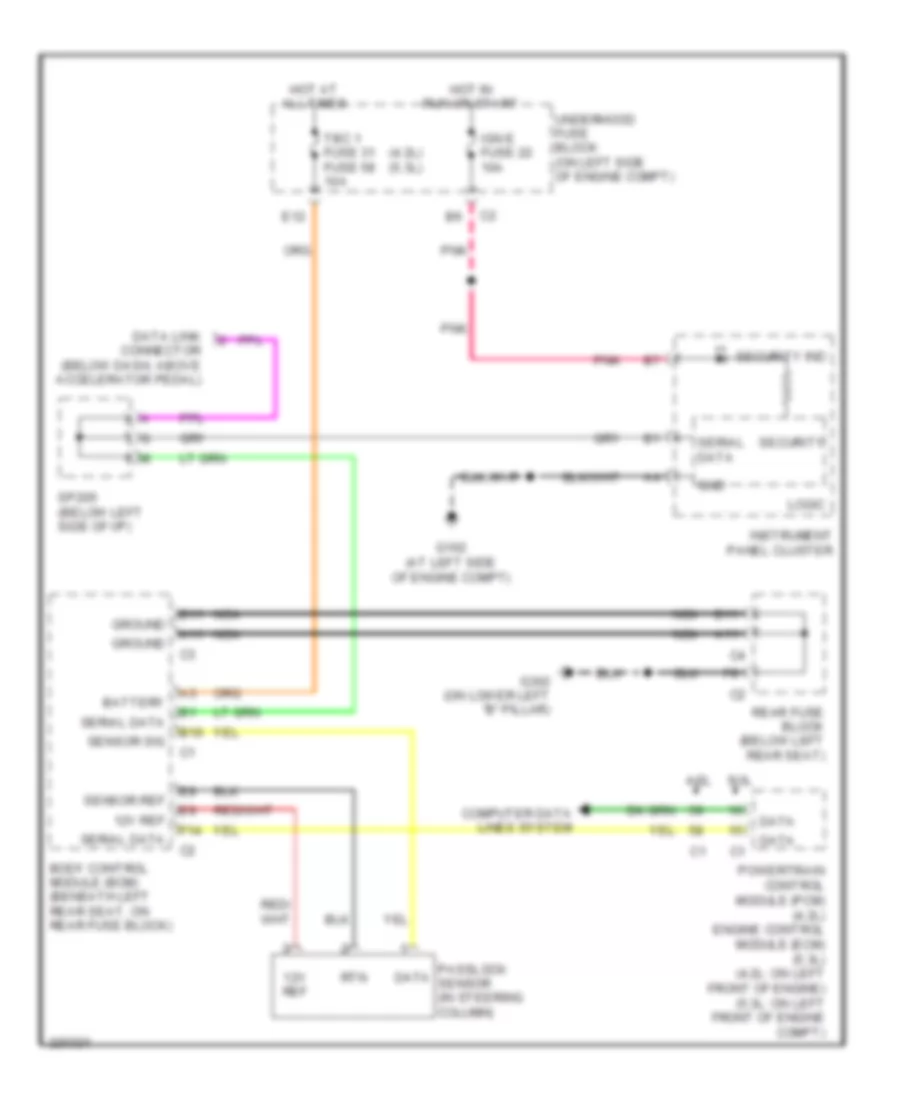
Immobilizer Wiring Diagram for Isuzu Ascender LS 2005
List of elements for Immobilizer Wiring Diagram for Isuzu Ascender LS 2005:
- (4.2l) (5.3l)
- 12v ref
- 4.2l
- 5.3l
- A11
- B10
- B11
- Battery
- Body control module (bcm) (beneath left rear seat, on rear fuse block)
- Computer data lines system
- Data
- Data link connector (below dash, above accelerator pedal)
- E12
- F14
- G102 (at left side of engine compt)
- G302 (on lower left "b" pillar)
- Gnd
- Ground
- Hot at all times
- Hot in run or start
- Ign e fuse 22 10a
- Instrument panel cluster
- Logic
- Nca
- Passlock sensor (in steering column)
- Pnk
- Powertrain control module (pcm) (4.2l) engine control module (ecm) (5.3l) (4.2l: on left front of engine) (5.3l: on left front of engine compt)
- Rear fuse block (below left rear seat)
- Rtn
- Security
- Security ind
- Sensor ref
- Sensor sig
- Serial data
- Sp205 (below left side of i/p)
- Tbc 1 fuse 31 fuse 58 10a
- Underhood fuse block (on left side of engine compt)
 Čeština
 Dansk
Dansk Deutsch
 Ελληνικά
 English
 English
 Español
 Suomi
Suomi Français
 Français
 עברית
עברית Hrvatski
 Magyar
 Italiano
 日本語
日本語 한국어
한국어 Nederlands
 Polski
 Português
 Português
 Русский
 Slovenčina
 Slovenščina
 Svenska
 Türkçe
 中文 (中国)
 Română