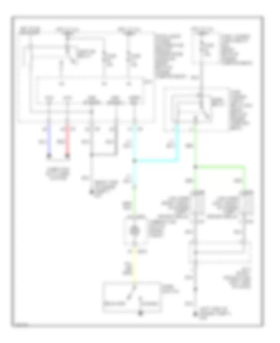
HORN
Horn Wiring Diagram for Infiniti FX45 2004
List of elements for Horn Wiring Diagram for Infiniti FX45 2004:
- (left side of engine compt) e50
- (right side of engine compt) e21
- +ig
- Can -h
- Can -l
- Combination switch (spiral cable)
- Computer data lines system
- Cpu
- E35
- E36
- E37
- E38
- Fuse 10a
- Fuse 15a
- Fuse, fusible link & relay box (right rear of engine compart- ment)
- Fuse, fusible link & relay box (right rear of engine compartment)
- Gnd (power)
- Gnd (signal)
- Horn relay
- Horn rly
- Horn switch
- Hot at all times
- Hot in on or start
- Ignition relay
- Intelligent power distribution module engine room (ipdm e/r) (right rear of engine compartment)
- J/c 2 (early production) (left side of dash)
- Low horn (left front of engine compt, behind grille)
- Low horn (right front of engine compt, behind grille)
- M15
- M203
- Pushed
- Red
- Released
 Čeština
 Dansk
Dansk Deutsch
 Ελληνικά
 English
 English
 Español
 Suomi
Suomi Français
 Français
 עברית
עברית Hrvatski
 Magyar
 Italiano
 日本語
日本語 한국어
한국어 Nederlands
 Polski
 Português
 Português
 Русский
 Slovenčina
 Slovenščina
 Svenska
 Türkçe
 中文 (中国)
 Română