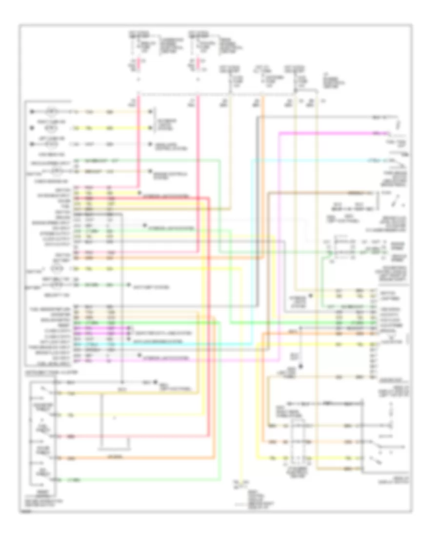
INSTRUMENT CLUSTER
Instrument Cluster Wiring Diagram for Buick Park Avenue 1997
List of elements for Instrument Cluster Wiring Diagram for Buick Park Avenue 1997:
- A10
- A11
- A12
- A13
- A14
- A15
- A16
- A17
- Anti-lock brakes system
- Anti-lock input
- Anti-theft system
- B10
- B11
- B12
- B13
- B14
- B15
- B16
- B17
- Battery
- Body control module (behind right side of i/p)
- Brake fluid input
- Brake fluid level switch (in master cylinder reservoir)
- C11
- Check engine ind
- Class 2 data
- Clock output
- Computer data lines system
- Cstr/sbm fuse 10a
- Data output
- Dim enable input
- Dim input
- Driver information center switch
- E/m switch
- Engine controls system
- Engine speed
- Engine speed input
- English/metric
- Exterior lights system
- Fuel
- Fuel level input
- Fuel sensor return
- Fuel switch
- Fuel tank unit
- G200 (left kick panel)
- G403 (right rear wheelhouse)
- Gauge
- Gauge switch
- Ground
- Head up display module (left top of i/p)
- Head up display switch
- Headlamps control system
- High beam ind
- Hot at all times
- Hot in run and start
- Hud clock
- Hud data
- Hud fuse 10a
- Hud motor
- Hud strobe
- Hud sw out
- Hvac fuse 10a
- I/p bussed electrical center
- Ignition
- Instrument panel cluster
- Interior lights system
- Lamp feed
- Left turn ind
- Odometer
- Odometer switch
- Park brake sw input
- Park brake switch (above park brake pedal)
- Pcm/cru fuse 10a
- Pnk
- Pnk e5
- Pnk f6
- Powertrain control module (left front of engine compt)
- Rear bussed electrical center
- Red
- Reset
- Reset switch
- Right turn ind
- S203
- S210
- S213
- S303
- Seat belt ind
- Security ind
- Smb/lcm fuse 10a
- Strobe output
- Tan
- Underhood bussed electrical center
- Uplevel
- Vehicle speed
- Vehicle speed input
- Vss signal
 Čeština
 Dansk
Dansk Deutsch
 Ελληνικά
 English
 English
 Español
 Suomi
Suomi Français
 Français
 עברית
עברית Hrvatski
 Magyar
 Italiano
 日本語
日本語 한국어
한국어 Nederlands
 Polski
 Português
 Português
 Русский
 Slovenčina
 Slovenščina
 Svenska
 Türkçe
 中文 (中国)
 Română