ANTI-LOCK BRAKES
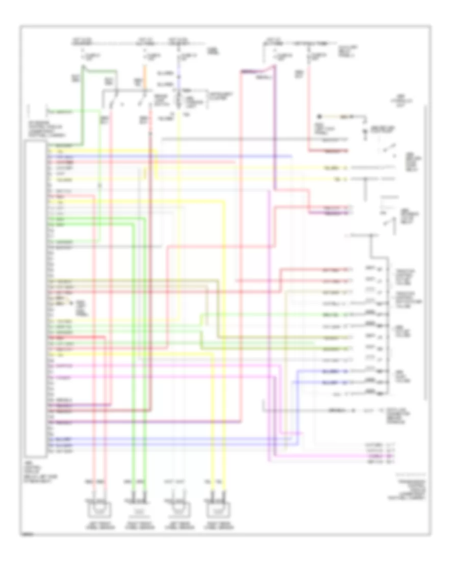
Anti-lock Brakes Wiring Diagram, FWD for Audi A6 1997
 https://portal-diagnostov.com/license.html
Automotive Electricians Portal FZCO
Automotive Electricians Portal FZCO
https://portal-diagnostov.com/license.html
https://portal-diagnostov.com/license.html
Automotive Electricians Portal FZCO
Automotive Electricians Portal FZCO
List of elements for Anti-lock Brakes Wiring Diagram, FWD for Audi A6 1997:
- (below left side
- Abs
- Abs inlet valves
- Abs outlet valves
- Abs return flow pump
- Abs return flow pump relay
- Abs solenoid valve relay
- Abs warning light
- All times
- Auxiliary relay panel 2
- Brake lamp switch
- Control
- Data link connector
- Fuse 15 5a
- Fuse 21 10a
- Fuse 53 50a
- Fuse 54 30a
- Fuse 9 10a
- Fuse panel
- G200 (left kick panel)
- Hot at
- Hot at all times
- Hot in on or start
- Hydraulic
- Instrument cluster
- Left front wheel sensor
- Left rear wheel sensor
- Mfi engine control module (under right footwell carpet)
- Module
- Of rear seat)
- Red
- Right front wheel sensor
- Right rear wheel sensor
- T26
- T26a
- Traction control outlet valves
- Traction control switch-over valves
- Unit
Anti-lock Brakes Wiring Diagram, Quattro for Audi A6 1997
List of elements for Anti-lock Brakes Wiring Diagram, Quattro for Audi A6 1997:
- (below left side
- Abs
- Abs control
- Abs inlet valves
- Abs outlet valves
- Abs return flow pump
- Abs return flow pump relay
- Abs solenoid valve relay
- Abs warning light
- All times
- Auxiliary relay panel 2
- Brake lamp switch
- Data link connector (behind console)
- Fuse 15 5a
- Fuse 21 10a
- Fuse 53 50a
- Fuse 54 30a
- Fuse 9 10a
- Fuse panel
- G200 (left kick panel)
- Hot at
- Hot at all times
- Hot in on or start
- Hydraulic
- Instrument cluster
- Left front wheel sensor
- Left rear wheel sensor
- Mfi engine control module (under right footwell carpet)
- Module
- Nca
- Of rear seat)
- Red
- Right front wheel sensor
- Right rear wheel sensor
- T26
- T26a
- Traction control outlet valves
- Traction control switch-over valves
- Transmission control module (under right footwell carpet)
- Unit

 Čeština
 Dansk
Dansk Deutsch
 Ελληνικά
 English
 English
 Español
 Suomi
Suomi Français
 Français
 עברית
עברית Hrvatski
 Magyar
 Italiano
 日本語
日本語 한국어
한국어 Nederlands
 Polski
 Português
 Português
 Русский
 Slovenčina
 Slovenščina
 Svenska
 Türkçe
 中文 (中国)