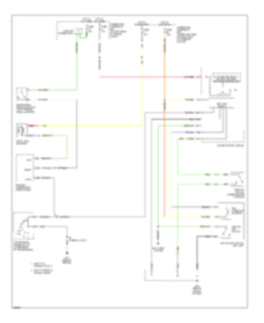
SHIFT INTERLOCK
Shift Interlock Wiring Diagram for Honda Fit 2007
List of elements for Shift Interlock Wiring Diagram for Honda Fit 2007:
- 5v stabilize circuit/ controller area network controller
- A17
- A19
- Anti-theft system
- Atpp
- B14
- Bksw
- Brake pedal position switch (top of brake pedal support)
- C11
- C22
- Canada: dx & lx
- Canada: sport
- D21
- E22
- Ecm/pcm (under right side of dash)
- Fuse 10a
- Fuse 15a
- Fuse 7.5a
- G101 (rear of engine)
- G402 (behind middle of dash)
- Gauge control module
- Hot at all times
- Hot in acc or on
- Hot in on or start
- I/f
- Ignition key switch
- Ignition key switch/ key light
- Junction connector a
- Key interlock solenoid
- Key lock circuit
- Park pin switch (under center console)
- Red
- S3 (thermal joint)
- Shift lock solenoid
- Sls
- Transmission range switch (lower rear of transmission)
- Under-dash fuse/relay box (under left side of dash, right of steering column)
- Under-hood fuse/relay box (at left rear of engine compt)
- Usa: fit &
- Usa: fit sport &
 Čeština
 Dansk
Dansk Deutsch
 Ελληνικά
 English
 English
 Español
 Suomi
Suomi Français
 Français
 עברית
עברית Hrvatski
 Magyar
 Italiano
 日本語
日本語 한국어
한국어 Nederlands
 Polski
 Português
 Português
 Русский
 Slovenčina
 Slovenščina
 Svenska
 Türkçe
 中文 (中国)
 Română