ANTI-LOCK BRAKES
Anti-lock Brake Wiring Diagrams for Mercury Mountaineer 1999
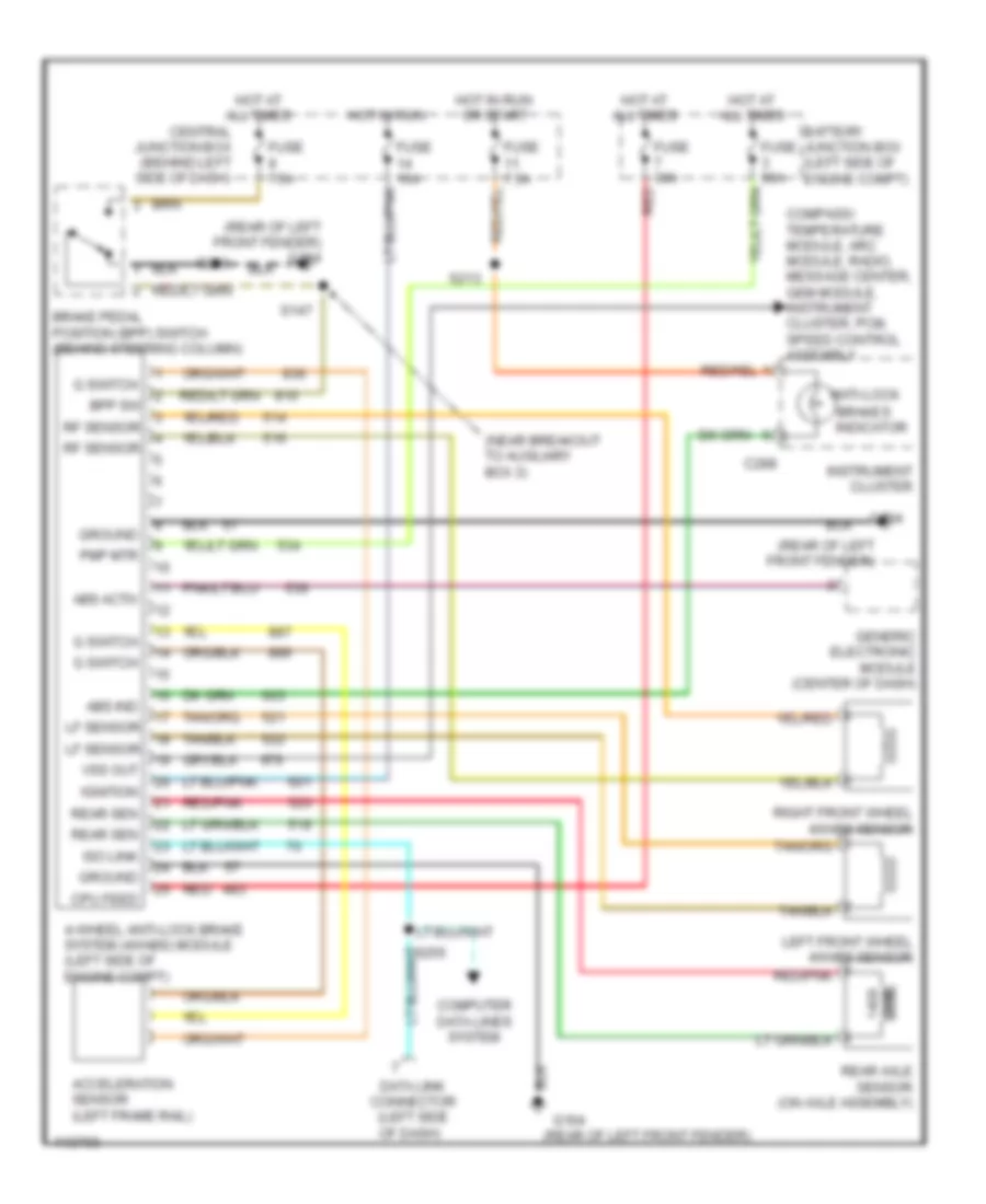
List of elements for Anti-lock Brake Wiring Diagrams for Mercury Mountaineer 1999:
- (near breakout to auxiliary box 3)
- (rear of left front fender)
- (rear of left front fender) g104
- 4-wheel anti-lock brake system (4wabs) module (left side of engine compt)
- Abs activ
- Abs ind
- Acceleration sensor (left frame rail)
- Anti-lock
- Battery junction box (left side of engine compt)
- Bpp sw
- Brake pedal position (bpp) switch (behind steering column)
- Brakes indicator
- C288
- Central junction box (behind left side of dash)
- Compass/ temperature module, arc module, radio, message center, gem module, instrument cluster, pcm, speed control assembly
- Computer data lines system
- Cpu feed
- Data link connector (left side of dash)
- Fuse 10a
- Fuse 30a
- Fuse 50a
- Fuse 7.5a
- G switch
- G104
- Generic electronic module (center of dash)
- Ground
- Hot at all times
- Hot in run
- Hot in run or start
- Ignition
- Instrument cluster
- Iso link
- Left front wheel 4wabs sensor
- Lf sensor
- Ohm
- Pmp mtr
- Rear axle sensor (on axle assembly)
- Rear sen
- Red
- Red/pnk
- Rf sensor
- Right front wheel 4wabs sensor
- S147
- S213
- S230
- Vss out
 Čeština
 Dansk
Dansk Deutsch
 Ελληνικά
 English
 English
 Español
 Suomi
Suomi Français
 Français
 עברית
עברית Hrvatski
 Magyar
 Italiano
 日本語
日本語 한국어
한국어 Nederlands
 Polski
 Português
 Português
 Русский
 Slovenčina
 Slovenščina
 Svenska
 Türkçe
 中文 (中国)
 Română