AIR CONDITIONING
3.1L
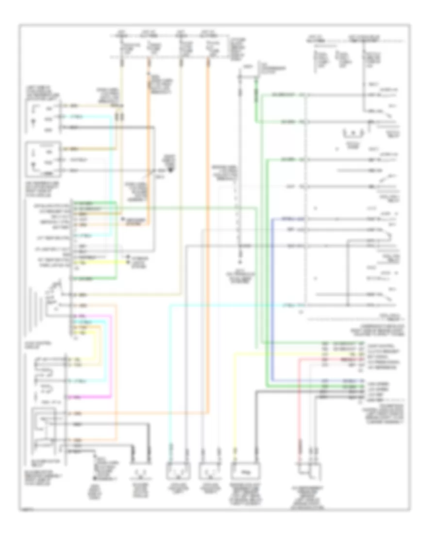
3.1L VIN J, Manual A/C Wiring Diagram for Pontiac Grand Prix GT 2002
 https://portal-diagnostov.com/license.html
Automotive Electricians Portal FZCO
Automotive Electricians Portal FZCO
https://portal-diagnostov.com/license.html
https://portal-diagnostov.com/license.html
Automotive Electricians Portal FZCO
Automotive Electricians Portal FZCO
List of elements for 3.1L VIN J, Manual A/C Wiring Diagram for Pontiac Grand Prix GT 2002:
- (dash harn, 4 cm from blower motor assembly)
- (dash harn, 4 cm from data link breakout) s206
- (engine harn, 4 cm from coolant fan breakout)
- (fuel inj harn, near breakout to map sensor)
- (left side of hvac module) air temperature actuator (left)
- (right side of dash) g200
- +5v reference
- A/c compressor clutch
- A/c clu diode
- A/c clu relay
- A/c clu/ abs ign fuse 28 10a
- A/c press signal
- A/c refrigerent pressure sensor (left side of engine compt, on accumulator)
- A/c request sig
- A10
- Air temperature actuator (right) (right side of hvac module)
- Battery
- Blower motor (in hvac module)
- Blower motor relay
- Blower motor resistor assembly (right side of hvac module)
- C10
- C11
- Clutch request
- Comp control
- Cool fan 1 fuse 6 30a
- Cool fan 2 fuse 1 30a
- Cool fan 1 relay
- Cool fan 2 relay
- Cool fan relay
- Cooling fan motor (left)
- Cooling fan motor (right)
- Defog rly ctrl
- Defogger system
- Dic/hvac fuse 10a
- Ect signal
- Engine controls system (map sensor)
- Engine coolant temperature (ect) sensor (top left rear of engine, below throttle body)
- F11
- G117 (on transaxle stud, near starter)
- G200 (right side of dash)
- Gnd
- High speed
- Hot at all times
- Hot in run
- Hot in run, bulb test or start
- Hvac control module
- Hvac ctrl fuse 20a
- Hvac hi fuse 30a
- I/p fuse block (behind right side of dash)
- I/p lamp sply volt
- Ign
- Ign 3 volt
- Interior lights system
- Lft temp dr ctrl
- Low ref
- Low reference
- Low speed
- Nca
- Nca nca
- Off
- Off blwr mtr ctrl
- P10
- P11
- Park lmp sw on
- Pos
- Powertrain control module (pcm) (left front side of engine compt, in air cleaner assembly)
- R10
- R11
- Radio fuse 10a
- Rt temp dr ctrl
- S105
- S121
- S213
- T10
- T11
- Tan
- U11
- Underhood fuse block (right side of engine compt, mounted to strut tower)
- V10
- V11
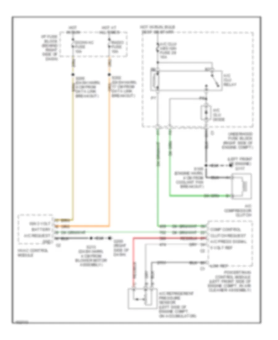
Compressor Wiring Diagram for Pontiac Grand Prix GT 2002
List of elements for Compressor Wiring Diagram for Pontiac Grand Prix GT 2002:
- (left front of engine) g117
- 5 volt ref
- A/c clu diode
- A/c clu relay
- A/c clu/ abs ign fuse 28 10a
- A/c compressor clutch
- A/c press signal
- A/c refrigerent pressure sensor (left side of engine compt, on accumulator)
- A/c request
- Battery
- C11
- Clutch request
- Comp control
- Dic/hvac fuse 10a
- G200 (right side of dash)
- Gnd
- Hot at all times
- Hot in run
- Hot in run, bulb test or start
- Hvac control module
- I/p fuse block (behind right side of dash)
- Ign 3 volt
- Low ref
- Powertrain control module (left front side of engine compt, in air cleaner assembly)
- Radio fuse 10a
- S105 (engine harn, 4 cm from coolant fan breakout)
- S213 (dash harn, 4 cm from blower motor assembly)
- Underhood fuse block (right side of engine compt)
3.8L
3.8L VIN 1, Manual A/C Wiring Diagram for Pontiac Grand Prix GT 2002
List of elements for 3.8L VIN 1, Manual A/C Wiring Diagram for Pontiac Grand Prix GT 2002:
- (dash harn, 4 cm from blower motor assembly)
- (dash harn, 4 cm from data link breakout) s206
- (engine harn, 4 cm from coolant fan breakout)
- (left side of hvac module) air temperature actuator (left)
- (right side of dash) g200
- +5v reference
- A/c compressor clutch
- A/c clu diode
- A/c clu relay
- A/c clu/ abs ign fuse 28 10a
- A/c press signal
- A/c refrigerent pressure sensor (left side of engine compt, on accumulator)
- A/c request sig
- A10
- Air temperature actuator (right) (right side of hvac module)
- Battery
- Blower motor (in hvac module)
- Blower motor relay
- Blower motor resistor assembly (right side of hvac module)
- C10
- C11
- Clutch request
- Comp control
- Cool fan 1 fuse 6 30a
- Cool fan 2 fuse 1 30a
- Cool fan 1 relay
- Cool fan 2 relay
- Cool fan relay
- Cooling fan motor (left)
- Cooling fan motor (right)
- Defog rly ctrl
- Defogger system
- Dic/hvac fuse 10a
- Ect signal
- Engine coolant temperature (ect) sensor (top left rear of engine, below throttle body)
- F11
- G117 (on transaxle stud, near starter)
- G200 (right side of dash)
- Gnd
- High speed
- Hot at all times
- Hot in run
- Hot in run, bulb test or start
- Hvac control module
- Hvac ctrl fuse 20a
- Hvac hi fuse 30a
- I/p fuse block (behind right side of dash)
- I/p lamp sply volt
- Ign
- Ign 3 volt
- Interior lights system
- Lft temp dr ctrl
- Low ref
- Low speed
- Nca
- Nca nca
- Off
- Off blwr mtr ctrl
- P10
- P11
- Park lmp sw on
- Pos
- Powertrain control module (pcm) (left front side of engine compt, in air cleaner assembly)
- R10
- R11
- Radio fuse 10a
- Rt temp dr ctrl
- S105
- S213
- T10
- T11
- Tan
- U11
- Underhood fuse block (right side of engine compt, mounted to strut tower)
- V10
- V11
3.8L VIN K, Manual A/C Wiring Diagram for Pontiac Grand Prix GT 2002
List of elements for 3.8L VIN K, Manual A/C Wiring Diagram for Pontiac Grand Prix GT 2002:
- (dash harn, 4 cm from blower motor assembly)
- (dash harn, 4 cm from data link breakout) s206
- (engine harn, 4 cm from coolant fan breakout)
- (left side of hvac module) air temperature actuator (left)
- (right side of dash) g200
- +5v reference
- A/c compressor clutch
- A/c clu diode
- A/c clu relay
- A/c clu/ abs ign fuse 28 10a
- A/c press signal
- A/c refrigerent pressure sensor (left side of engine compt, on accumulator)
- A/c request sig
- A10
- Air temperature actuator (right) (right side of hvac module)
- Battery
- Blower motor (in hvac module)
- Blower motor relay
- Blower motor resistor assembly (right side of hvac module)
- C10
- C11
- Clutch request
- Comp control
- Cool fan 1 fuse 6 30a
- Cool fan 2 fuse 1 30a
- Cool fan 1 relay
- Cool fan 2 relay
- Cool fan relay
- Cooling fan motor (left)
- Cooling fan motor (right)
- Defog rly ctrl
- Defogger system
- Dic/hvac fuse 10a
- Ect signal
- Engine coolant temperature (ect) sensor (top left rear of engine, below throttle body)
- F11
- G117 (on transaxle stud, near starter)
- G200 (right side of dash)
- Gnd
- High speed
- Hot at all times
- Hot in run
- Hot in run, bulb test or start
- Hvac control module
- Hvac ctrl fuse 20a
- Hvac hi fuse 30a
- I/p fuse block (behind right side of dash)
- I/p lamp sply volt
- Ign
- Ign 3 volt
- Interior lights system
- Lft temp dr ctrl
- Low ref
- Low speed
- Nca
- Nca nca
- Off
- Off blwr mtr ctrl
- P10
- P11
- Park lmp sw on
- Pos
- Powertrain control module (pcm) (left front side of engine compt, in air cleaner assembly)
- R10
- R11
- Radio fuse 10a
- Rt temp dr ctrl
- S105
- S213
- T10
- T11
- Tan
- U11
- Underhood fuse block (right side of engine compt, mounted to strut tower)
- V10
- V11
Compressor Wiring Diagram for Pontiac Grand Prix GT 2002
List of elements for Compressor Wiring Diagram for Pontiac Grand Prix GT 2002:
- (left front of engine) g117
- 5 volt ref
- A/c clu diode
- A/c clu relay
- A/c clu/ abs ign fuse 28 10a
- A/c compressor clutch
- A/c press signal
- A/c refrigerent pressure sensor (left side of engine compt, on accumulator)
- A/c request
- Battery
- C11
- Clutch request
- Comp control
- Dic/hvac fuse 10a
- G200 (right side of dash)
- Gnd
- Hot at all times
- Hot in run
- Hot in run, bulb test or start
- Hvac control module
- I/p fuse block (behind right side of dash)
- Ign 3 volt
- Low ref
- Powertrain control module (left front side of engine compt, in air cleaner assembly)
- Radio fuse 10a
- S105 (engine harn, 4 cm from coolant fan breakout)
- S213 (dash harn, 4 cm from blower motor assembly)
- Underhood fuse block (right side of engine compt)

 Čeština
 Dansk
Dansk Deutsch
 Ελληνικά
 English
 English
 Español
 Suomi
Suomi Français
 Français
 עברית
עברית Hrvatski
 Magyar
 Italiano
 日本語
日本語 한국어
한국어 Nederlands
 Polski
 Português
 Português
 Русский
 Slovenčina
 Slovenščina
 Svenska
 Türkçe
 中文 (中国)