SUPPLEMENTAL RESTRAINTS
Supplemental Restraints Wiring Diagram for Pontiac Grand Prix GT 2004
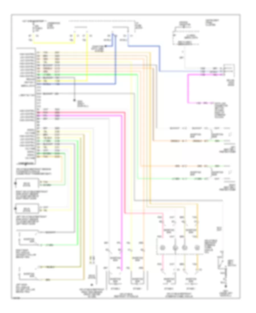
List of elements for Supplemental Restraints Wiring Diagram for Pontiac Grand Prix GT 2004:
- A10
- A11
- A12
- A13
- A14
- A15
- A16
- A17
- A18
- Air bag indicator
- Case ground
- Class 2 serial data
- Computer data lines system
- Data link connector (bottom of dash, right of steering column)
- G301 (inside left door sill)
- G302 (right door sill)
- Ground
- High control
- Hot in run & start
- I/p fuse block
- Ignition 1
- Inflatable restraint front end sensor (front center of car)
- Inflatable restraint i/p module
- Inflatable restraint sensing & diagnostic module (under front passenger seat)
- Inflatable restraint steering wheel module
- Inflatable restraint steering wheel module coil
- Instrument panel cluster
- L seat blt sw
- Left inflatable restraint side impact sensor (in lower center of left front door)
- Left roof rail module (on left c-pillar behind trim)
- Left seat belt pretentioner
- Low control
- Nca
- Pnk
- Right inflatable restraint side impact sensor (in lower center of right front door)
- Right roof rail module (on right c-pillar behind trim)
- Right seat belt pretentioner
- Sdm class 2 serial data
- Seat belt switch
- Serial data
- Shorting bar
- Signal
- Sir fuse 9 10a
- Solid state
- Splice pack sp205
- Stage 1
- Stage 2
- Tan
- Underhood fuse block
- Voltage
 Čeština
 Dansk
Dansk Deutsch
 Ελληνικά
 English
 English
 Español
 Suomi
Suomi Français
 Français
 עברית
עברית Hrvatski
 Magyar
 Italiano
 日本語
日本語 한국어
한국어 Nederlands
 Polski
 Português
 Português
 Русский
 Slovenčina
 Slovenščina
 Svenska
 Türkçe
 中文 (中国)
 Română