ANTI-LOCK BRAKES
Anti-lock Brake Wiring Diagrams for Mazda Protege LX 1998
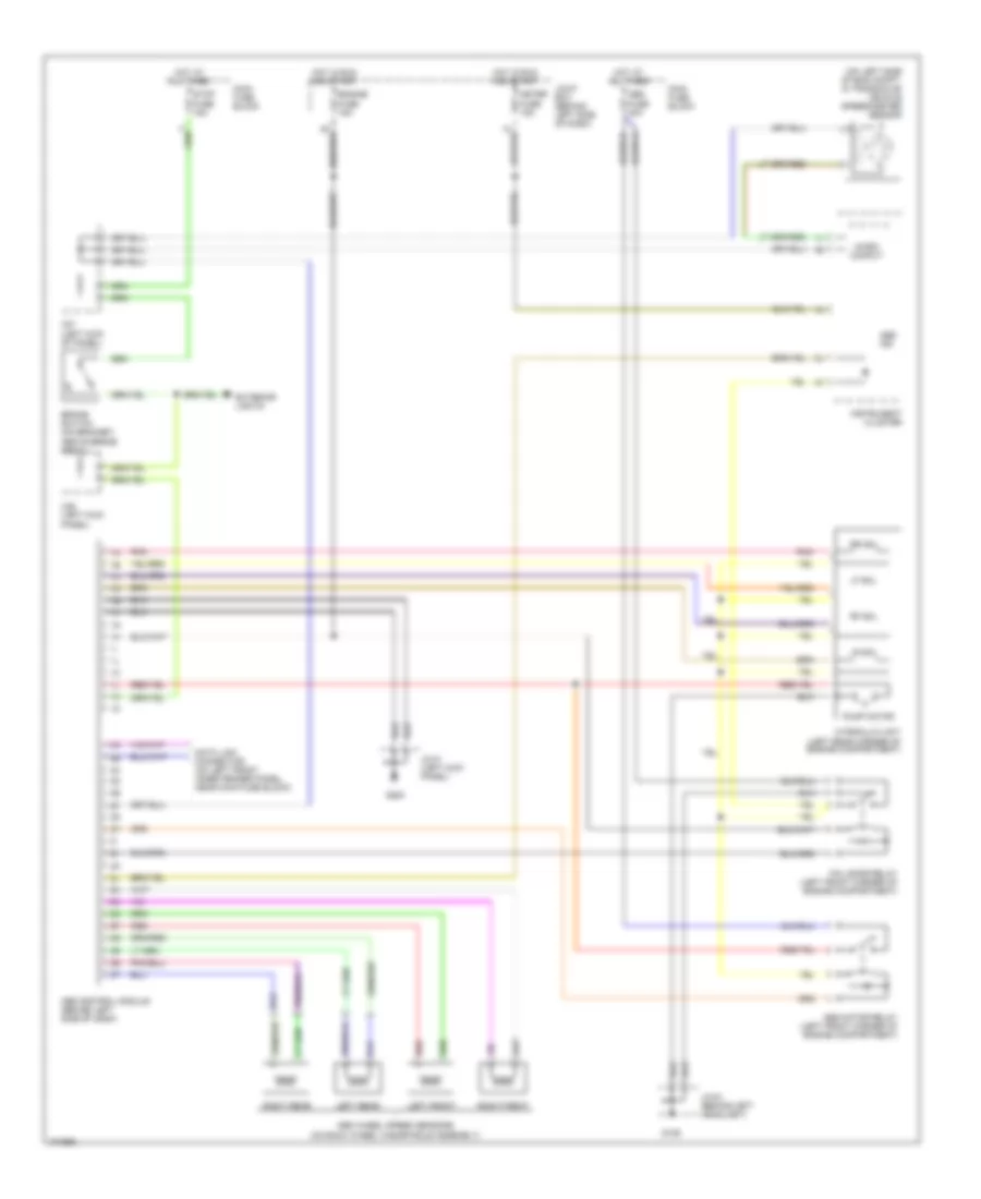
List of elements for Anti-lock Brake Wiring Diagrams for Mazda Protege LX 1998:
- (on left side of eng compt, in transaxle) vehicle speedometer sensor
- 2b
- Above brake pedal)
- Abs control module (behind left side of dash)
- Abs fuse 40a
- Abs ind
- Abs motor relay (left front corner of engine compartment)
- Abs wheel speed sensors (on each wheel hub/spindle assembly)
- Brake switch (on bracket,
- Data link connector (on left front inner fender panel, near main fuse block)
- Engine fuse 15a
- Exterior lights
- Fail-safe relay (left front corner of engine compartment)
- G106
- G200
- Hot at all times
- Hot in run and start
- Hydraulic unit (left rear corner of engine compartment)
- Instrument cluster
- Jc-01 (left kick panel)
- Jc-03 (behind left headlight)
- Joint box (behind left side of dash)
- Left front
- Left rear
- Lf sol
- Lr sol
- Main fuse block
- Meter fuse 15a
- Micro comput
- Of panel)
- Panel)
- Pnk
- Pump motor
- Red
- Rf sol
- Right front
- Right rear
- Rr sol
- Stop fuse 15a
- X25 (left kick
- X27 (left kick
 Čeština
 Dansk
Dansk Deutsch
 Ελληνικά
 English
 English
 Español
 Suomi
Suomi Français
 Français
 עברית
עברית Hrvatski
 Magyar
 Italiano
 日本語
日本語 한국어
한국어 Nederlands
 Polski
 Português
 Português
 Русский
 Slovenčina
 Slovenščina
 Svenska
 Türkçe
 中文 (中国)
 Română