ANTI-LOCK BRAKES
Anti-lock Brakes Wiring Diagram for Suzuki Aerio SX 2003
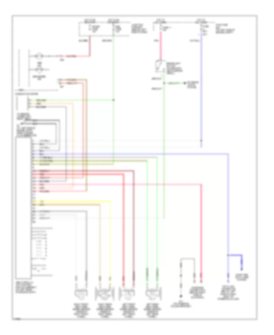
List of elements for Anti-lock Brakes Wiring Diagram for Suzuki Aerio SX 2003:
- "g" sensor (under left front seat)
- Abs fuse 10a
- Abs hydraulic unit/control module assembly (on left rear of engine compt)
- Abs ind
- Brake/ebd ind
- Brakelight switch (on bracket, above brake pedal)
- Combination meter
- Computer data lines system
- Cpu
- Data link connector (below left side of dash, right of steering column)
- Diagnosis connector 2 (behind right side of glove box)
- E17
- Exterior lights system
- Fuse 11 15a
- Fuse 60a
- G11 (on steering column bracket)
- G20
- G21
- G7 (at left side of engine compt, near washer fluid reservoir)
- Hot at all times
- Hot in on or start
- Junction/ fuse box (behind left side of dash)
- Left front abs wheel speed sensor (inside of left front wheel)
- Left rear abs wheel speed sensor (inside of left rear wheel)
- Main fuse box (on left side of engine compt)
- Meter fuse 10a
- Pnk
- Red
- Right front abs wheel speed sensor (inside of right front wheel)
- Right rear abs wheel speed sensor (inside of right rear wheel)
 Čeština
 Dansk
Dansk Deutsch
 Ελληνικά
 English
 English
 Español
 Suomi
Suomi Français
 Français
 עברית
עברית Hrvatski
 Magyar
 Italiano
 日本語
日本語 한국어
한국어 Nederlands
 Polski
 Português
 Português
 Русский
 Slovenčina
 Slovenščina
 Svenska
 Türkçe
 中文 (中国)
 Română