SHIFT INTERLOCK
Shift Interlock Wiring Diagram for Toyota Land Cruiser 2007
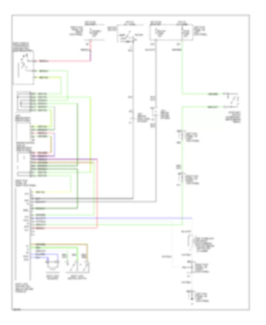
List of elements for Shift Interlock Wiring Diagram for Toyota Land Cruiser 2007:
- (right side of transmission) park/neutral position switch
- Acc
- Alt
- At4
- C16
- C17
- C19
- C20
- D10
- D16
- D27
- D30
- D31
- D35
- E18
- E26
- Ecu-ig1 fuse 10a
- Engine control module (behind right side of dash)
- Gauge 2 fuse 10a
- Hot at all times
- Hot in on or start
- Ignition switch
- J/b 4 (behind center of dash)
- J/b 6 (behind right side of dash)
- J/b 7 (behind right side of dash)
- Key interlock solenoid (on steering column, behind ignition key cylinder)
- Kls+
- Left kick panel j/b (left kick panel)
- Lock
- Nssl
- Off
- P10
- P11
- P12
- P13
- P14
- Right kick panel j/b (right kick panel)
- Shift lock control ecu (below center console)
- Shift lock control switch
- Shift lock solenoid
- Sls+
- Sls-
- Start
- Stop fuse 15a
- Stoplight switch (on bracket, above brake pedal)
- Stp
 Čeština
 Dansk
Dansk Deutsch
 Ελληνικά
 English
 English
 Español
 Suomi
Suomi Français
 Français
 עברית
עברית Hrvatski
 Magyar
 Italiano
 日本語
日本語 한국어
한국어 Nederlands
 Polski
 Português
 Português
 Русский
 Slovenčina
 Slovenščina
 Svenska
 Türkçe
 中文 (中国)
 Română