AIR CONDITIONING
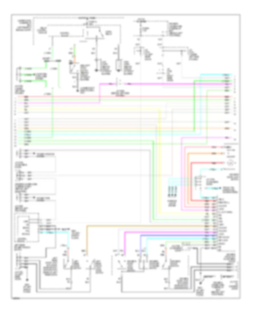
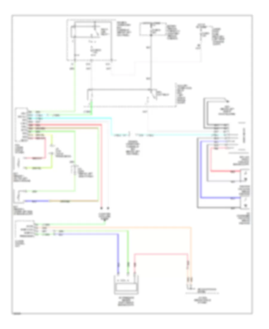
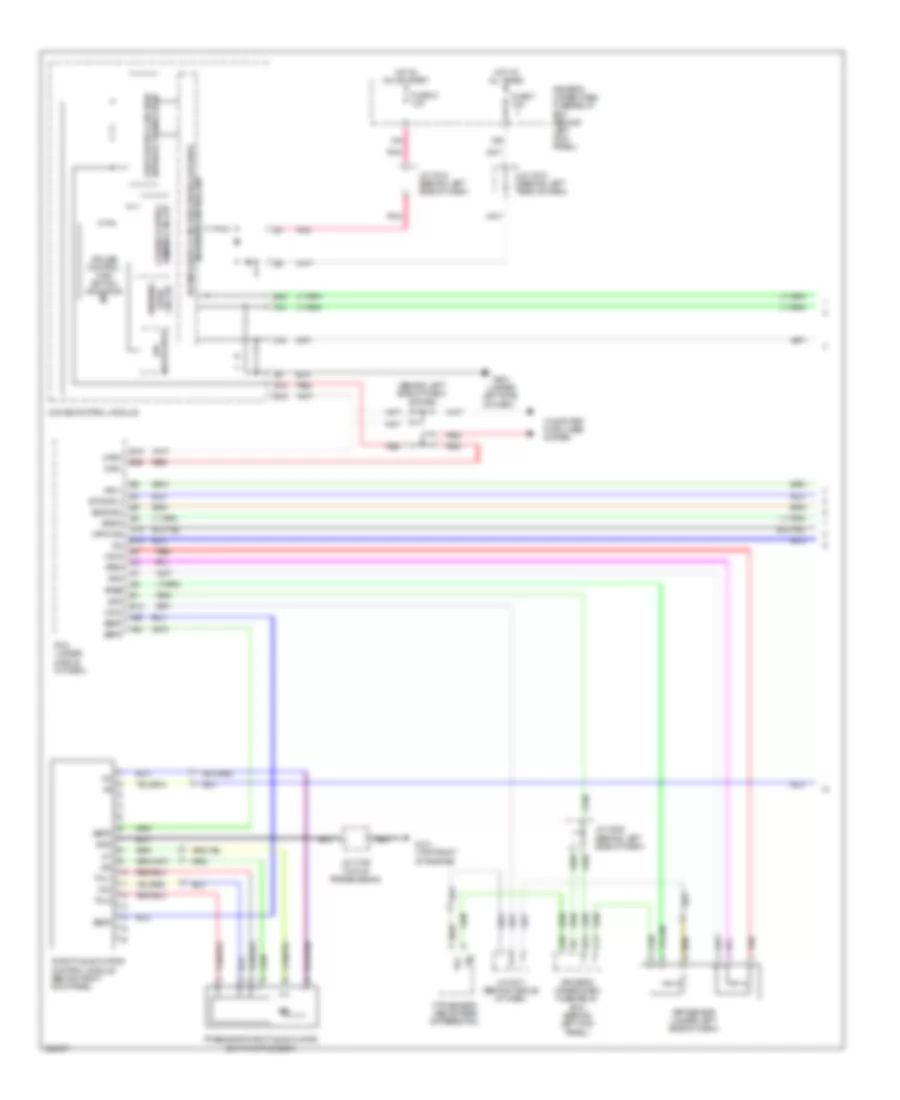
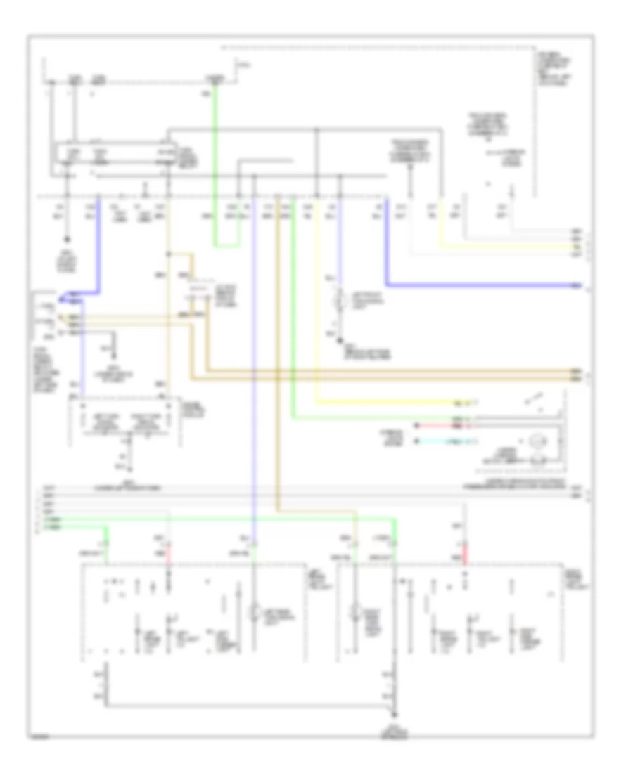
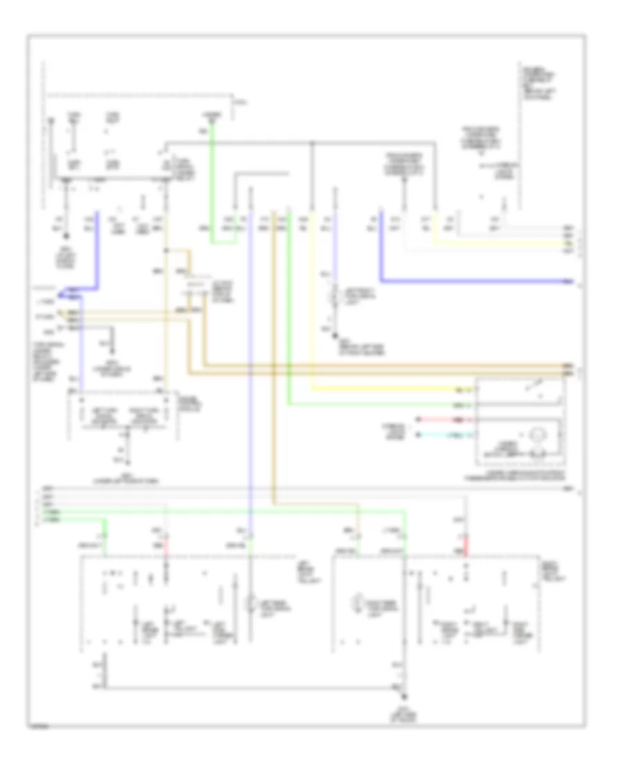
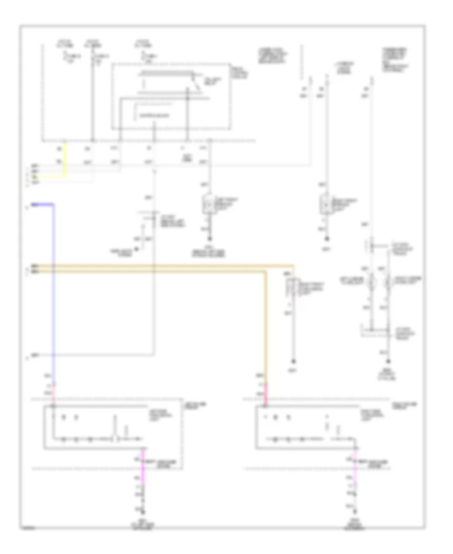
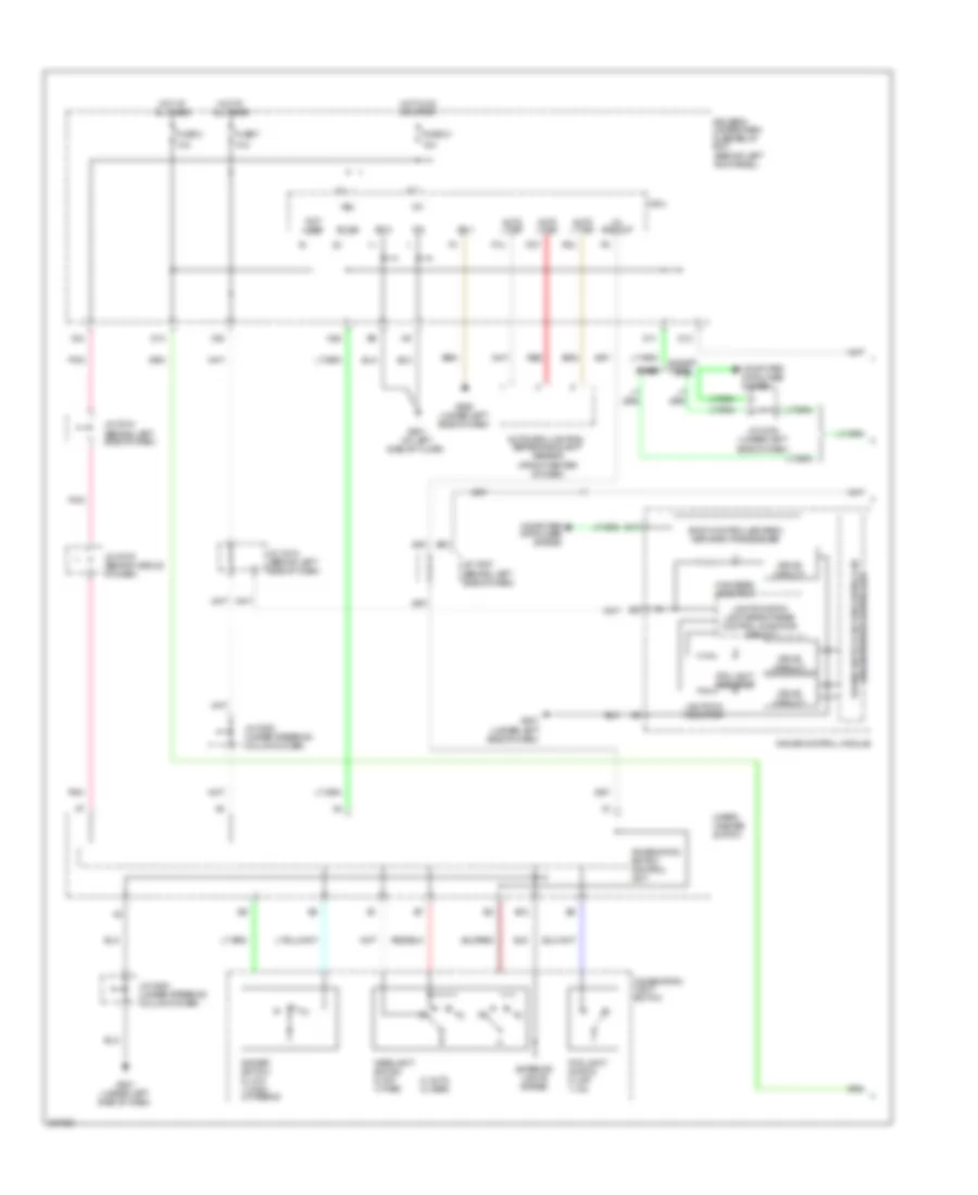
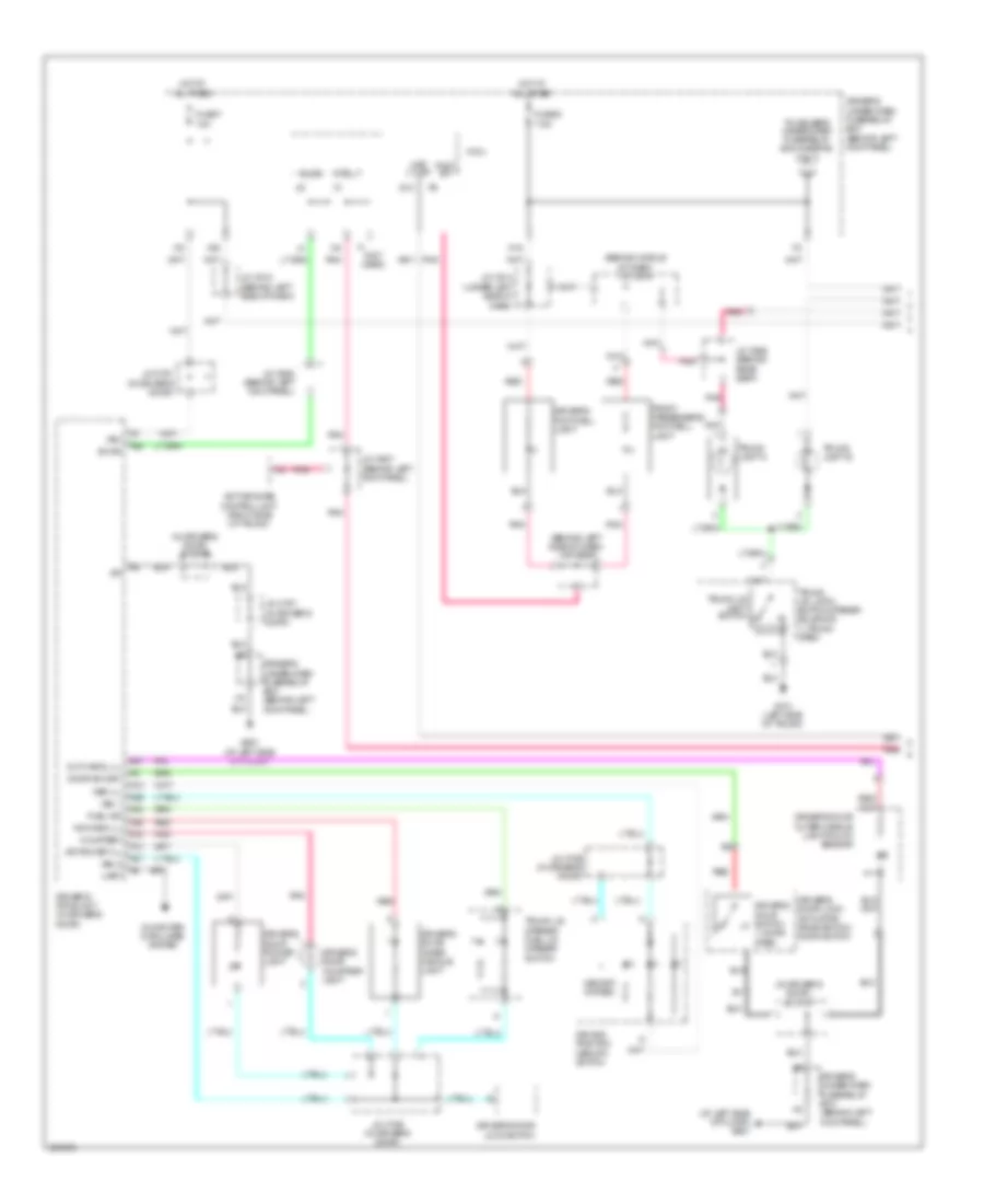
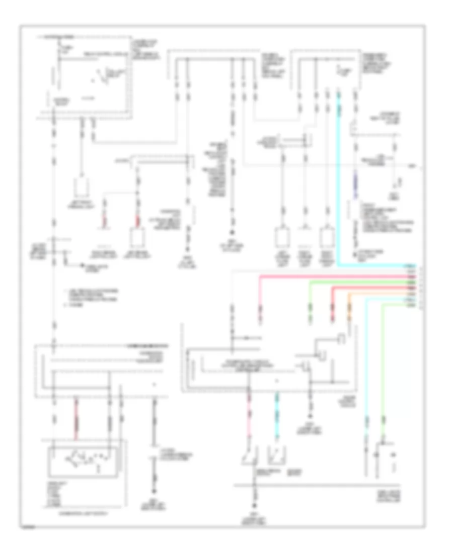
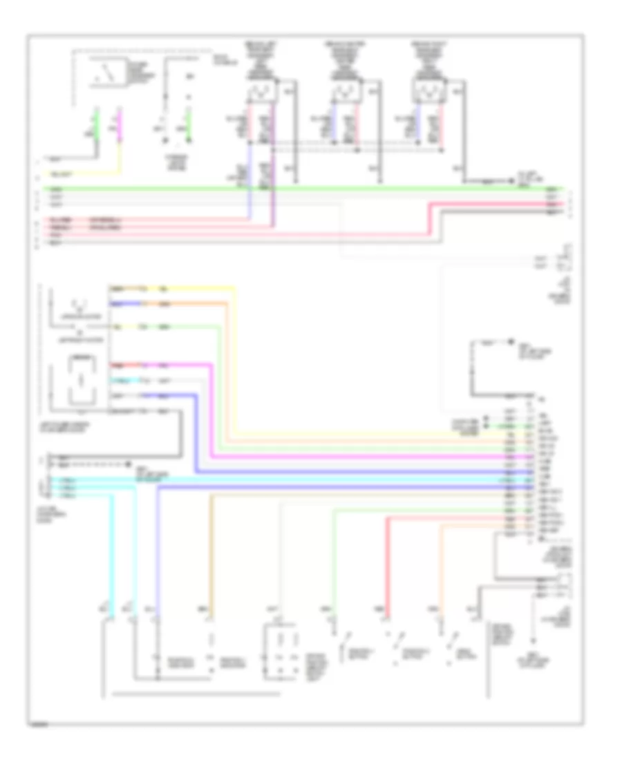
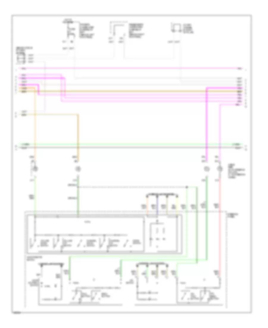
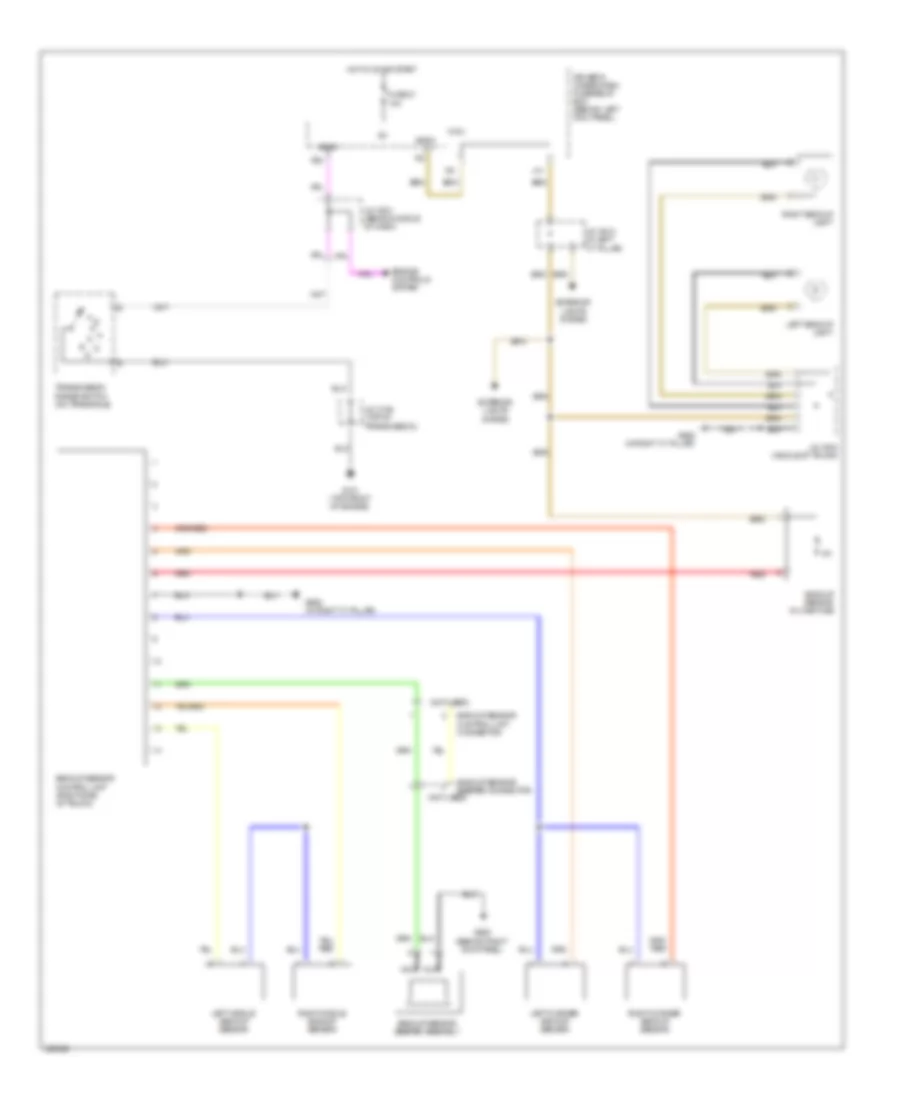
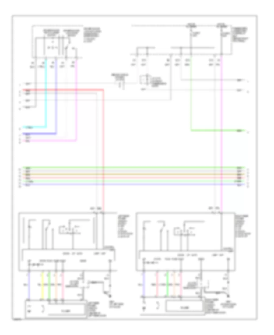
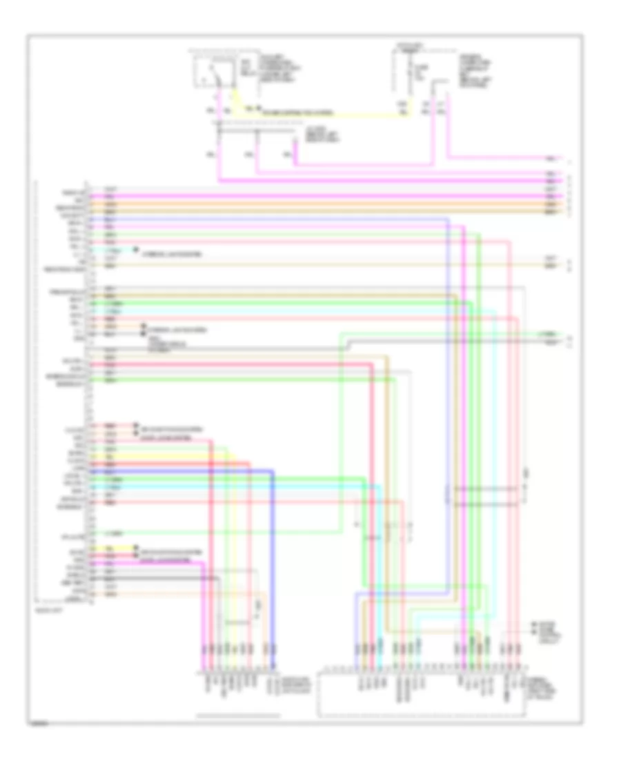
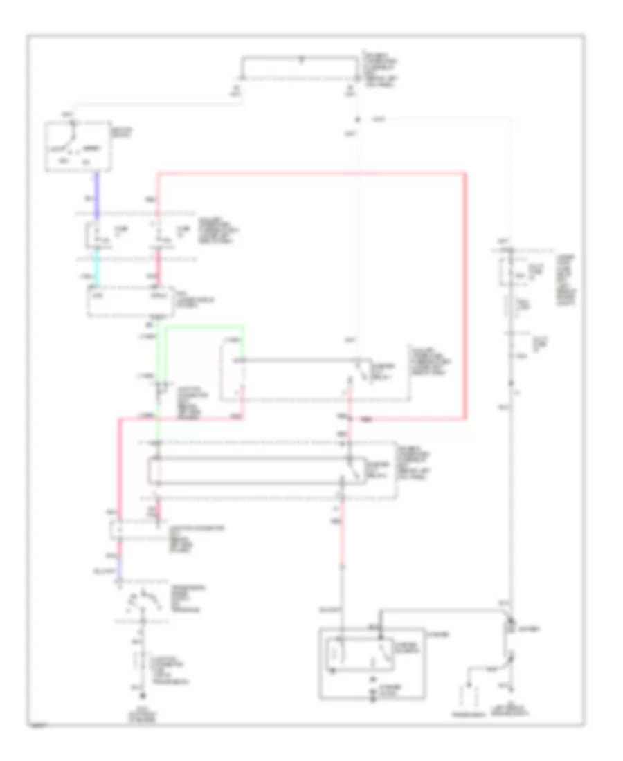
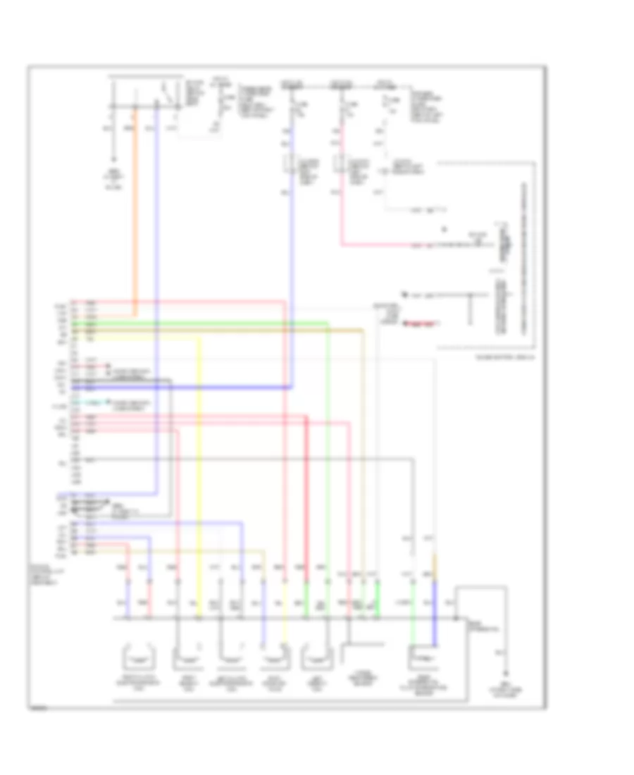
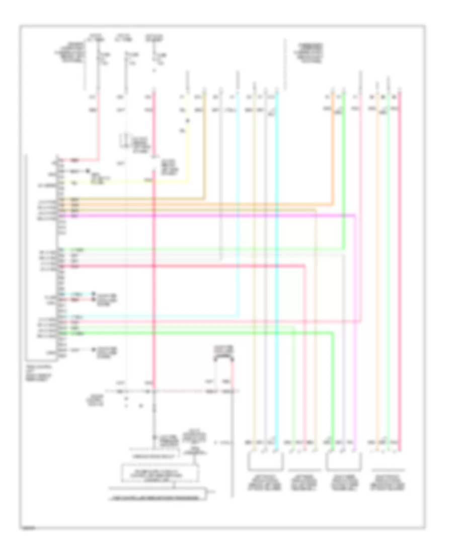
Automatic A/C Wiring Diagram (1 of 3) for Acura RL 2010
 https://portal-diagnostov.com/license.html
Automotive Electricians Portal FZCO
Automotive Electricians Portal FZCO
https://portal-diagnostov.com/license.html
https://portal-diagnostov.com/license.html
Automotive Electricians Portal FZCO
Automotive Electricians Portal FZCO
List of elements for Automatic A/C Wiring Diagram (1 of 3) for Acura RL 2010:
- A/c compressor
- A/c compressor clutch
- A/c pressure sensor (right side of engine compt)
- Aspirator fan
- Automatic lighting sensor/ sunlight sensor (front center of dash)
- B-can
- Blower motor (under right side of dash)
- Blower power transistor (behind right side of dash, left of blower motor)
- Blwr feedback
- Climate control unit
- Clk
- Clk ac
- Com gnd
- Com pwr
- Computer data lines system
- Ctrl mtr rly
- Driver's under-dash fuse/relay box (behind left kick panel)
- Driver's vent air temperature sensor (behind left side of gauge control module)
- Evaporator temperature sensor (under left side of dash)
- Front passenger's vent air temperature sensor (under right side of dash)
- Fuse 30 7.5a
- Fuse 9 7.5a
- G501 (under left side of dash)
- G503 (under middle of dash)
- G506 (behind glove box)
- Gnd
- Hot at all times
- Hot in on
- Hvac control motor relay
- Ig2
- Ill+
- Ill-
- In-car temperature sensor (on dash, right of steering column)
- Interior lights system
- J/c c517 (behind middle of dash)
- J/c c521 (behind middle of dash)
- J/c c524 (behind middle of dash)
- N20
- Outside air temperature sensor (behind right side of front bumper)
- Passenger's under-dash fuse/relay box (behind right kick panel)
- Pnk
- Press snsr
- Red
- Seats system
- Sens com
- Snsr 5v
- So ac
- Sol in
- Sol out
- Sunlight sens
- Temp sens
- Temperature sensor
- Trans ctrl
- Variable capacity control solenoid valve
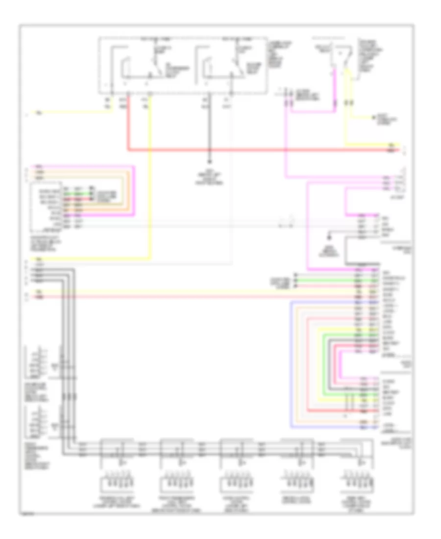
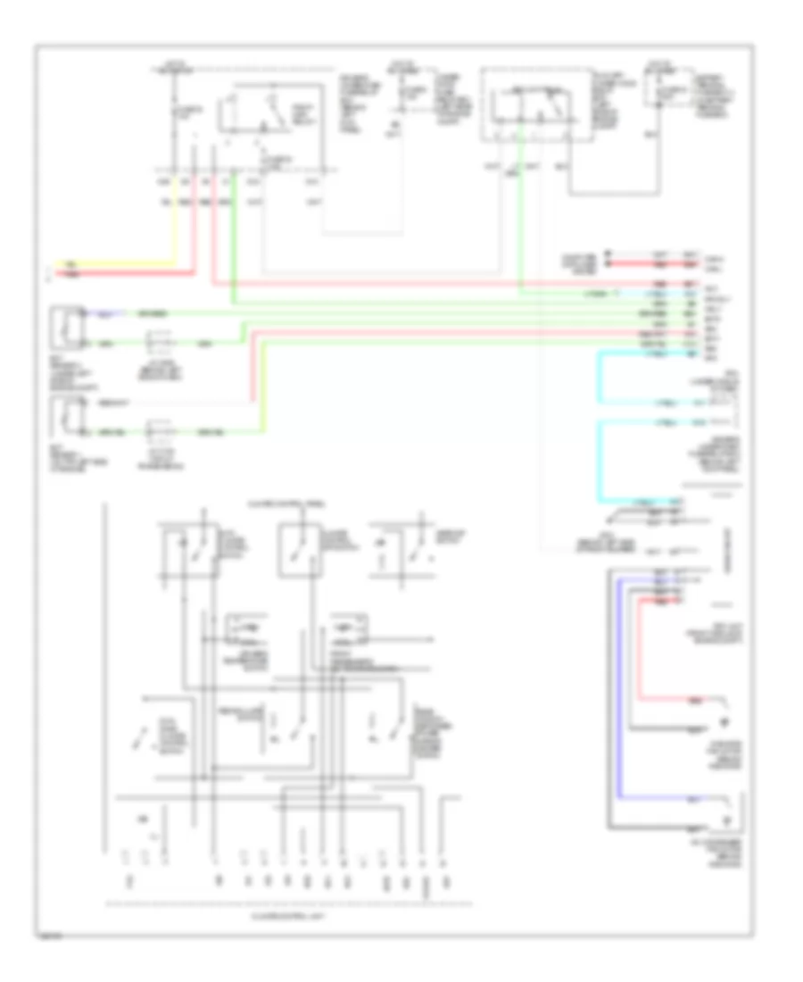
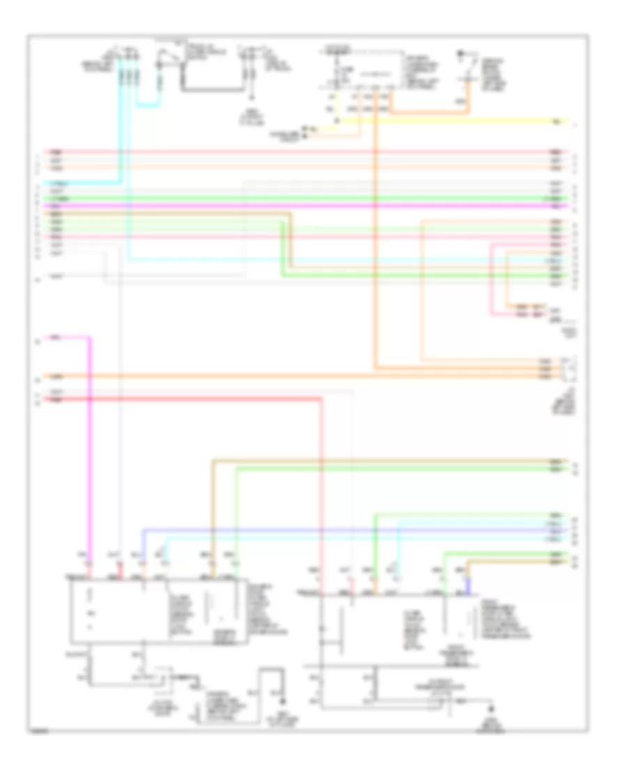
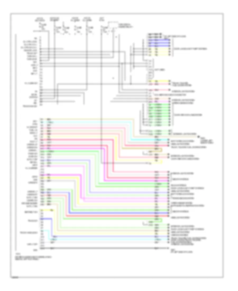
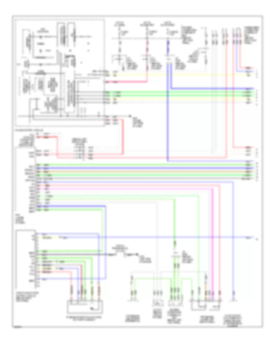
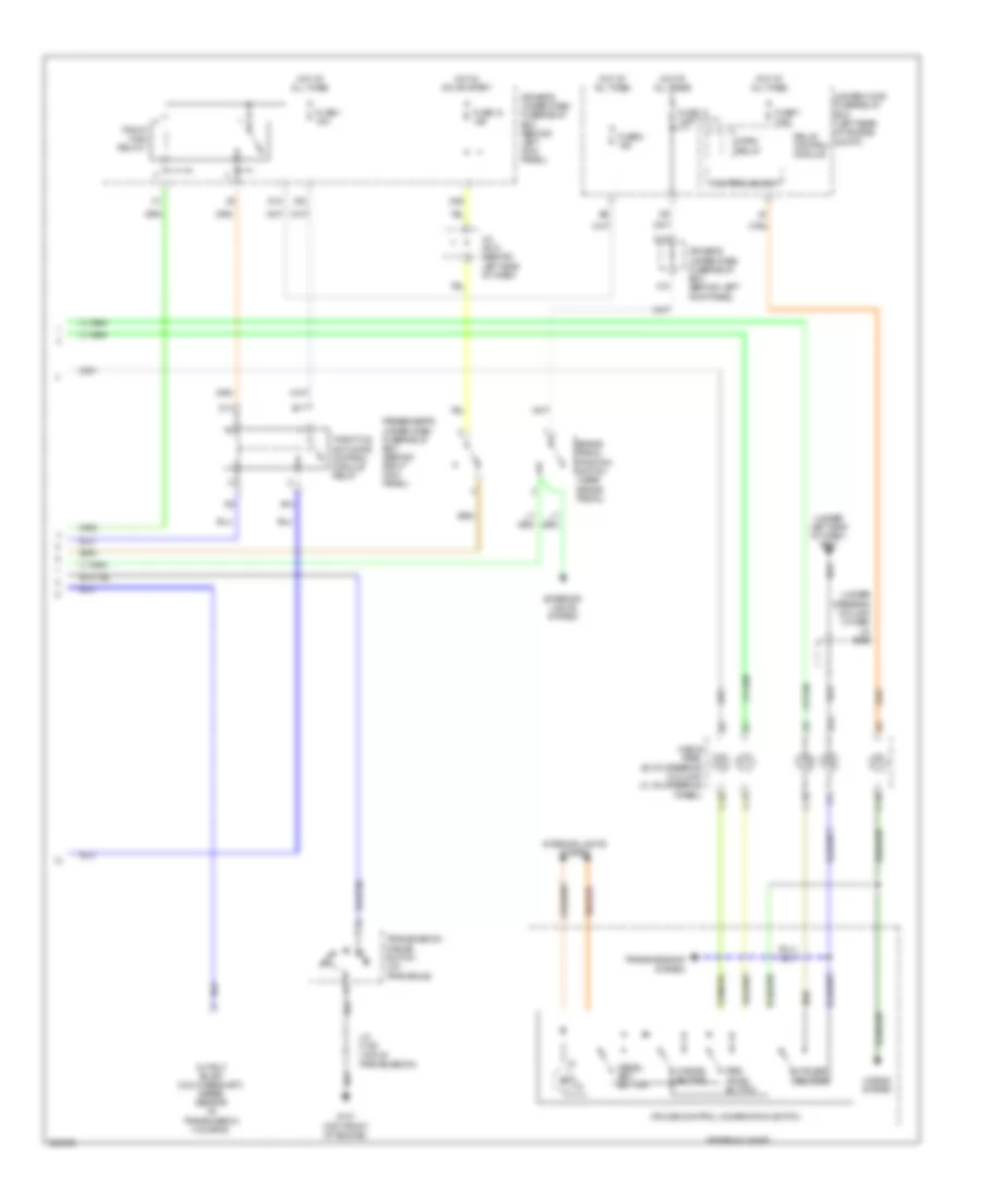
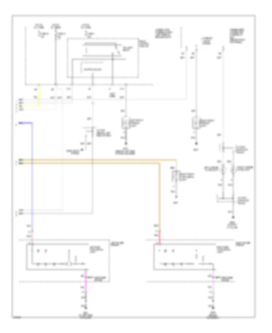
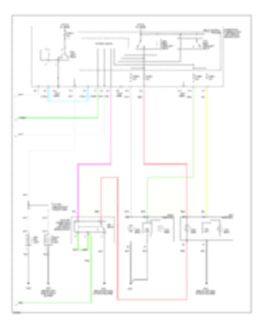
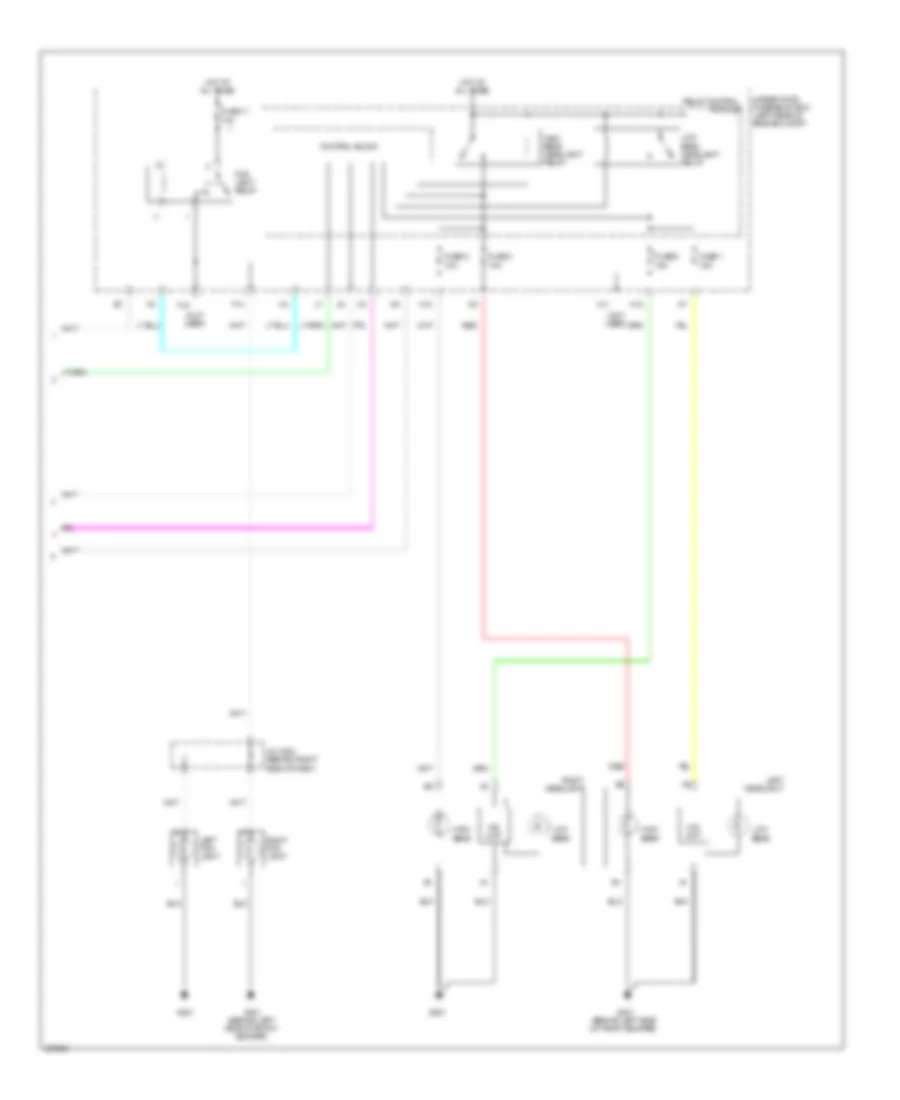
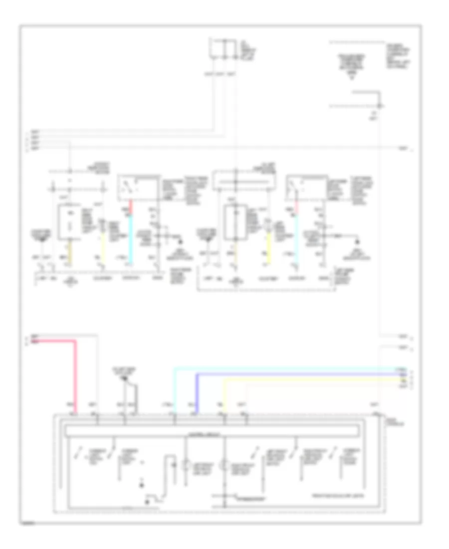
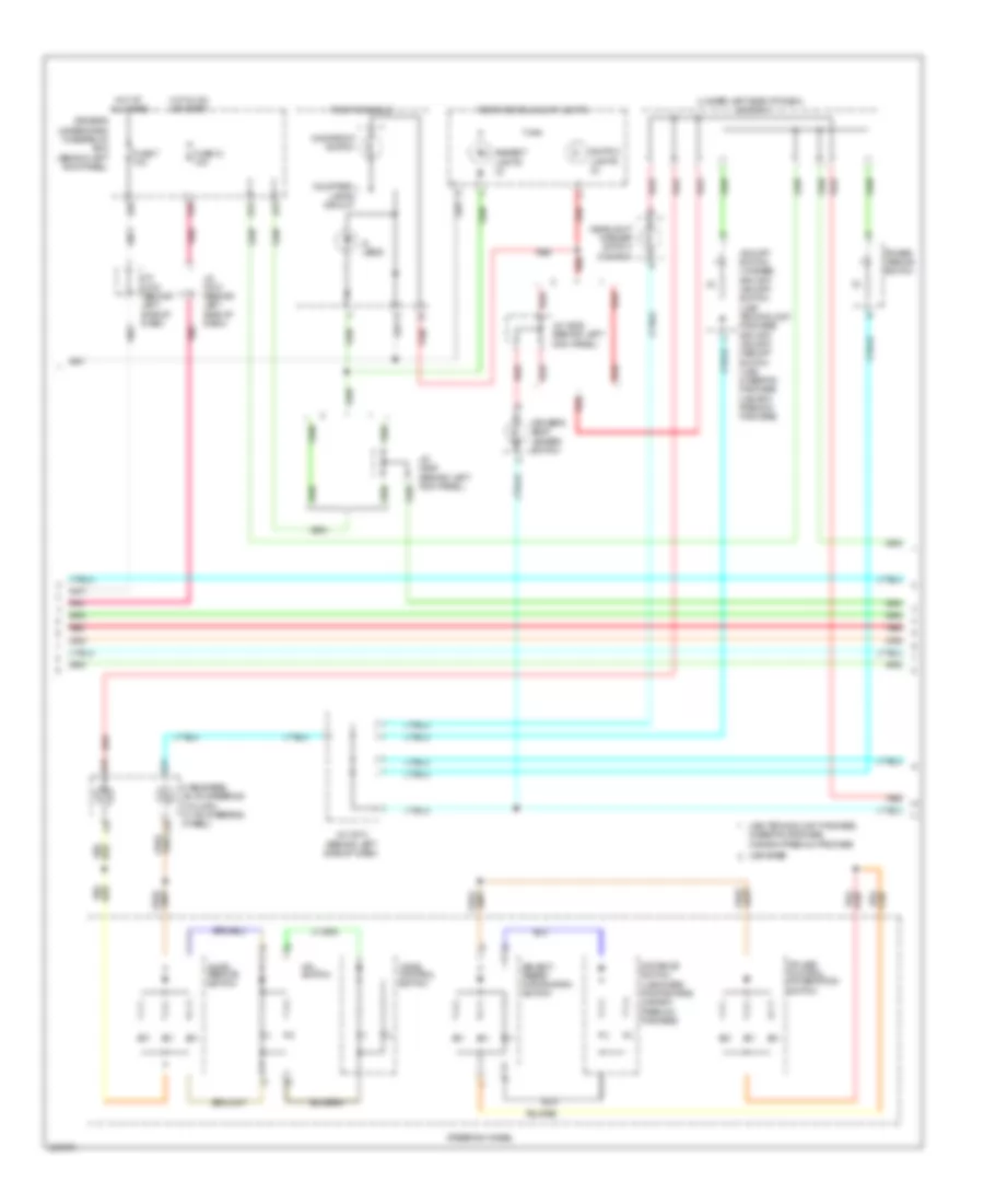
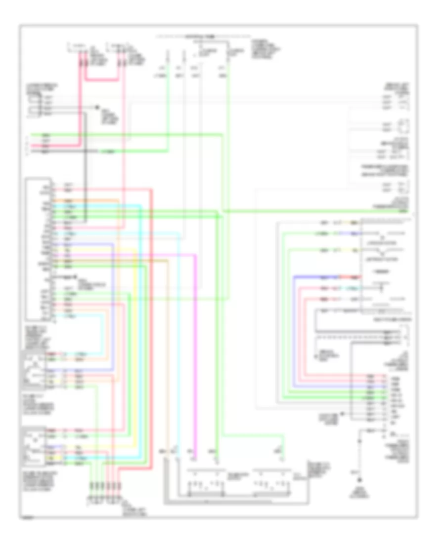
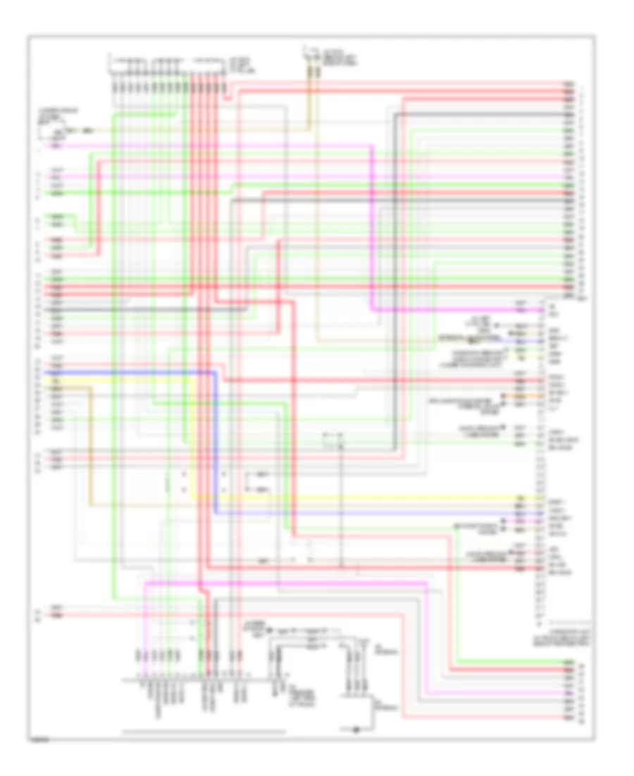
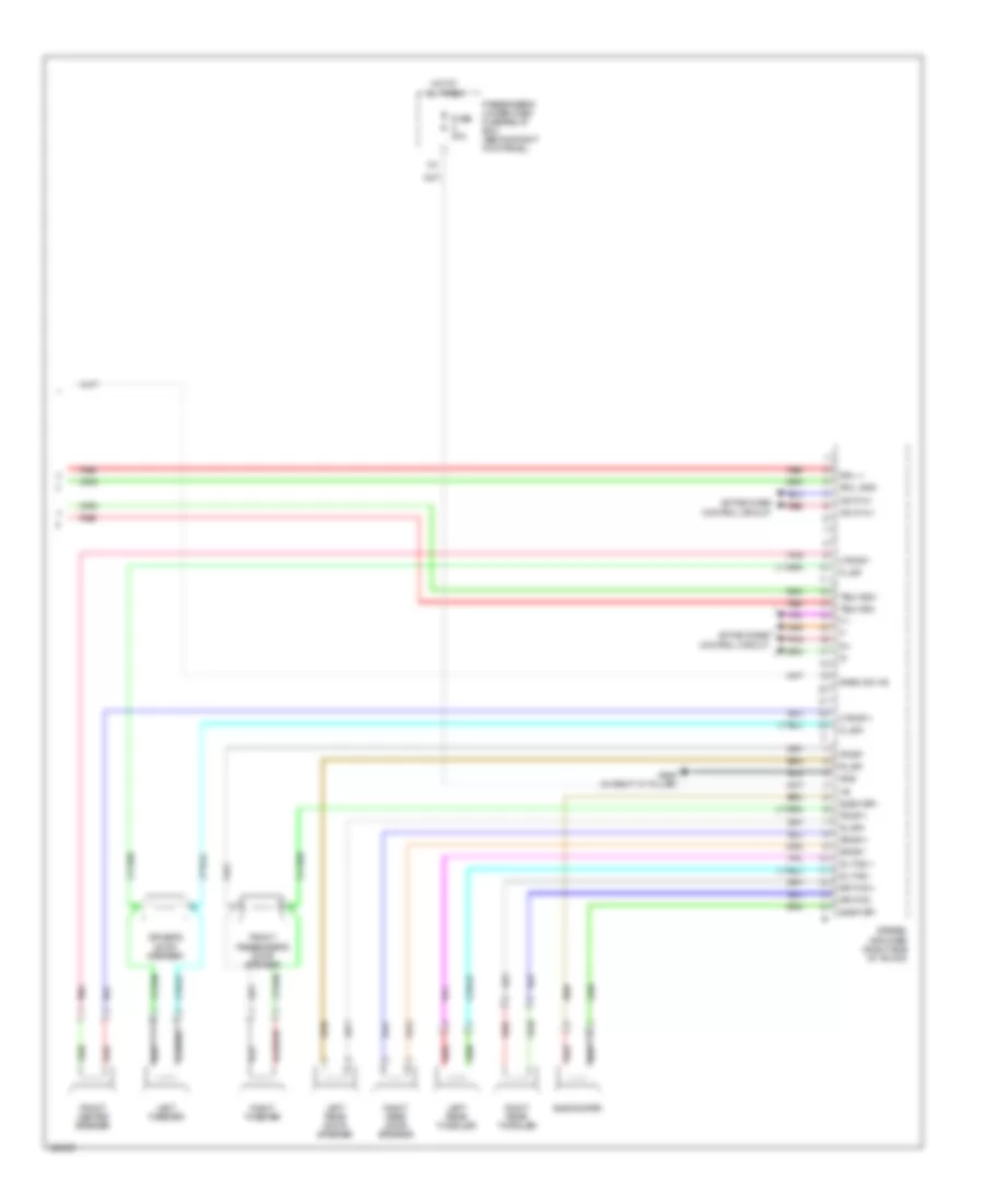
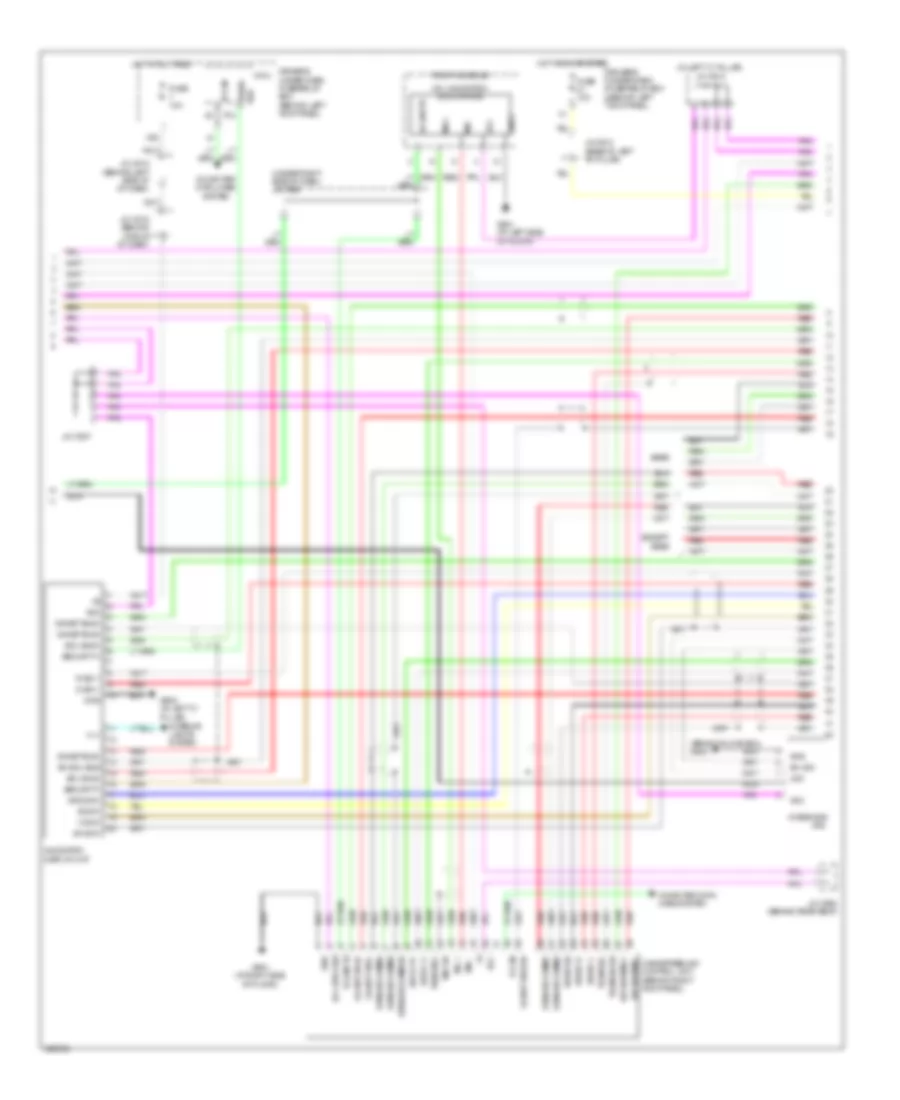
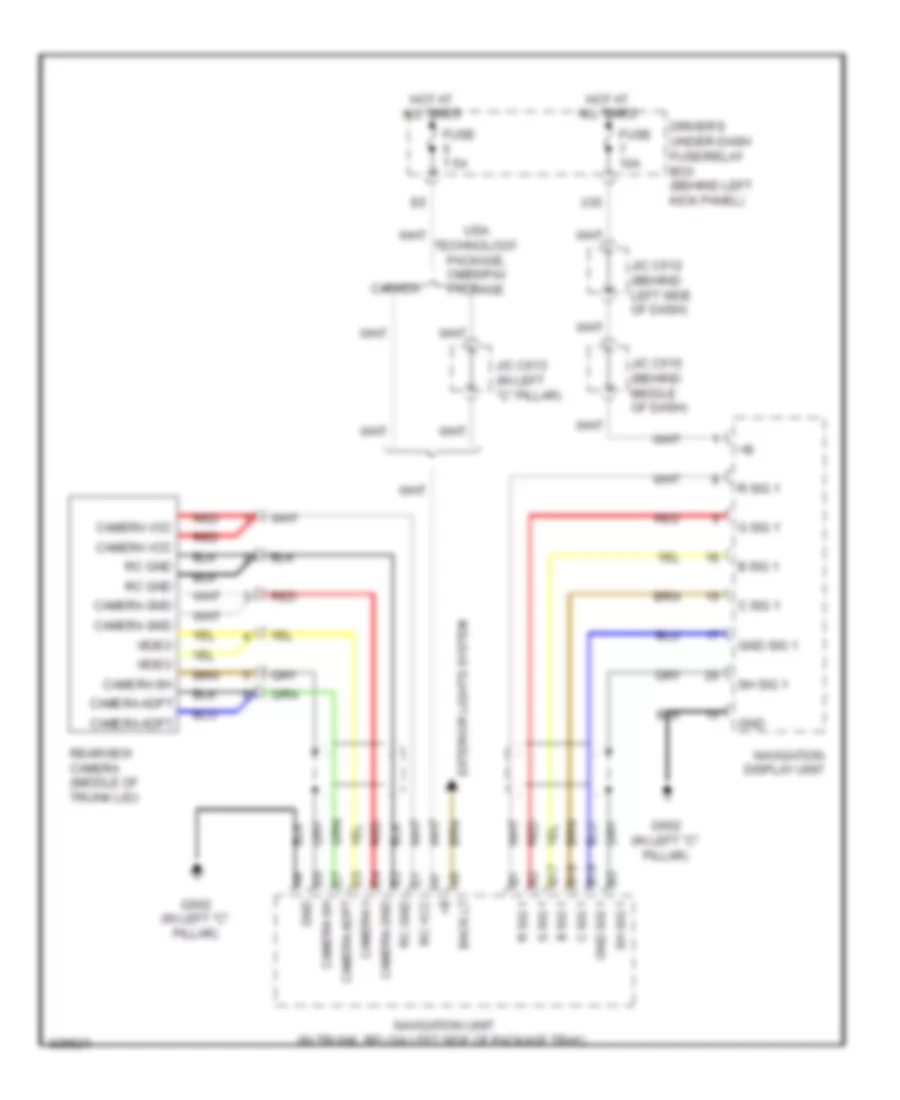
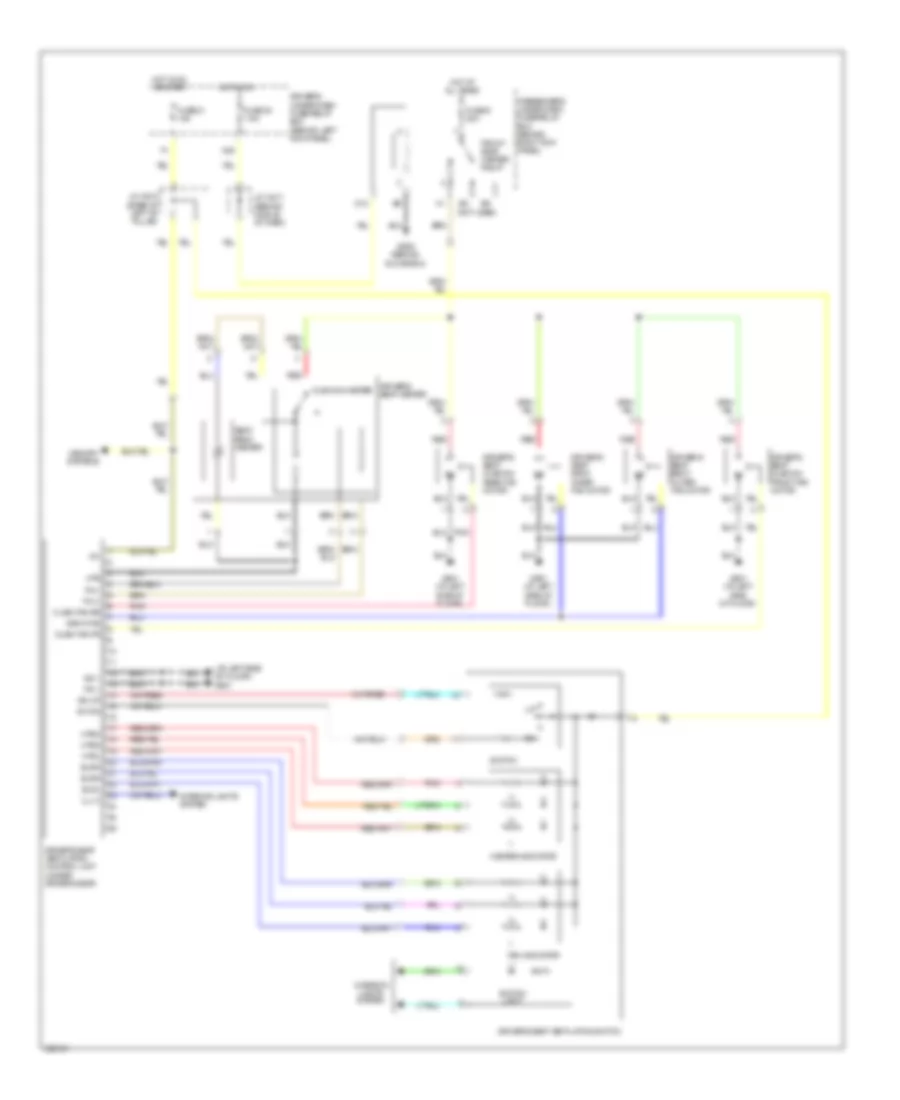
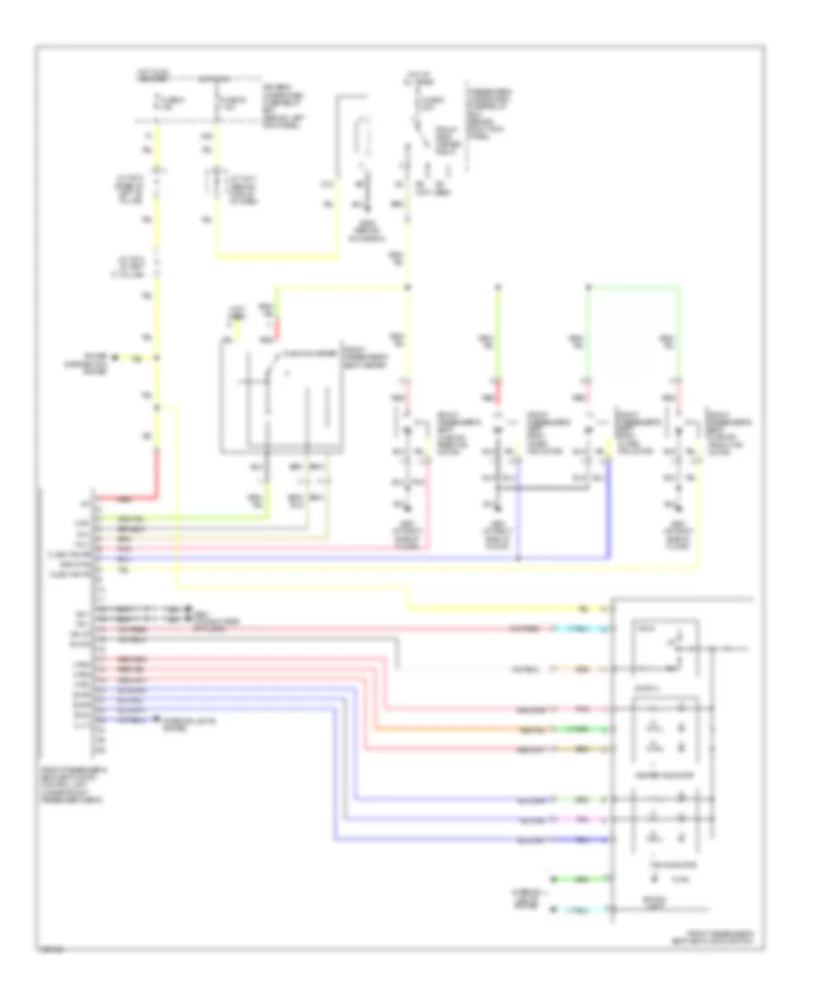
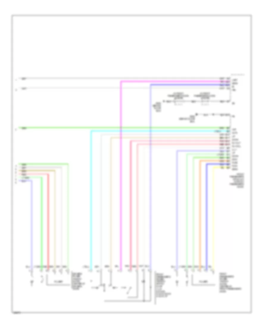
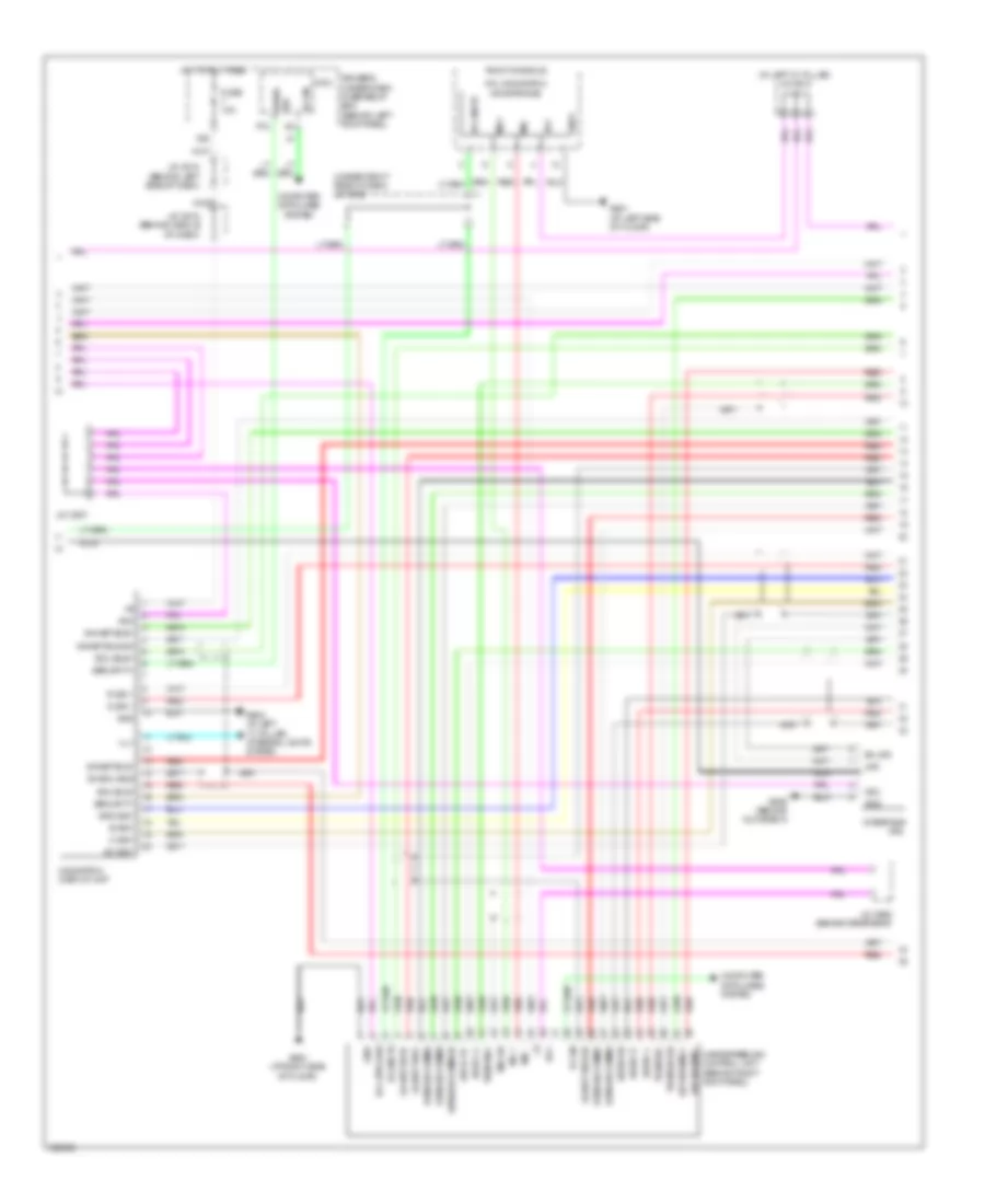
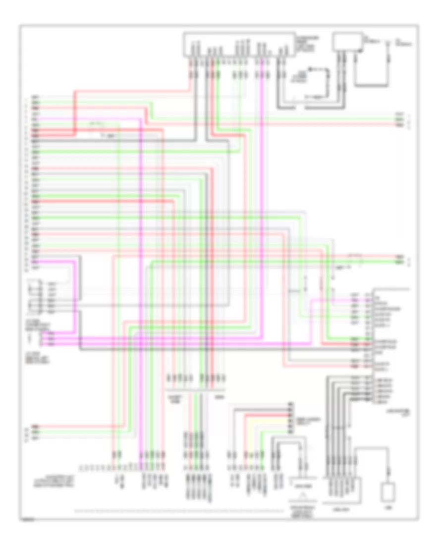
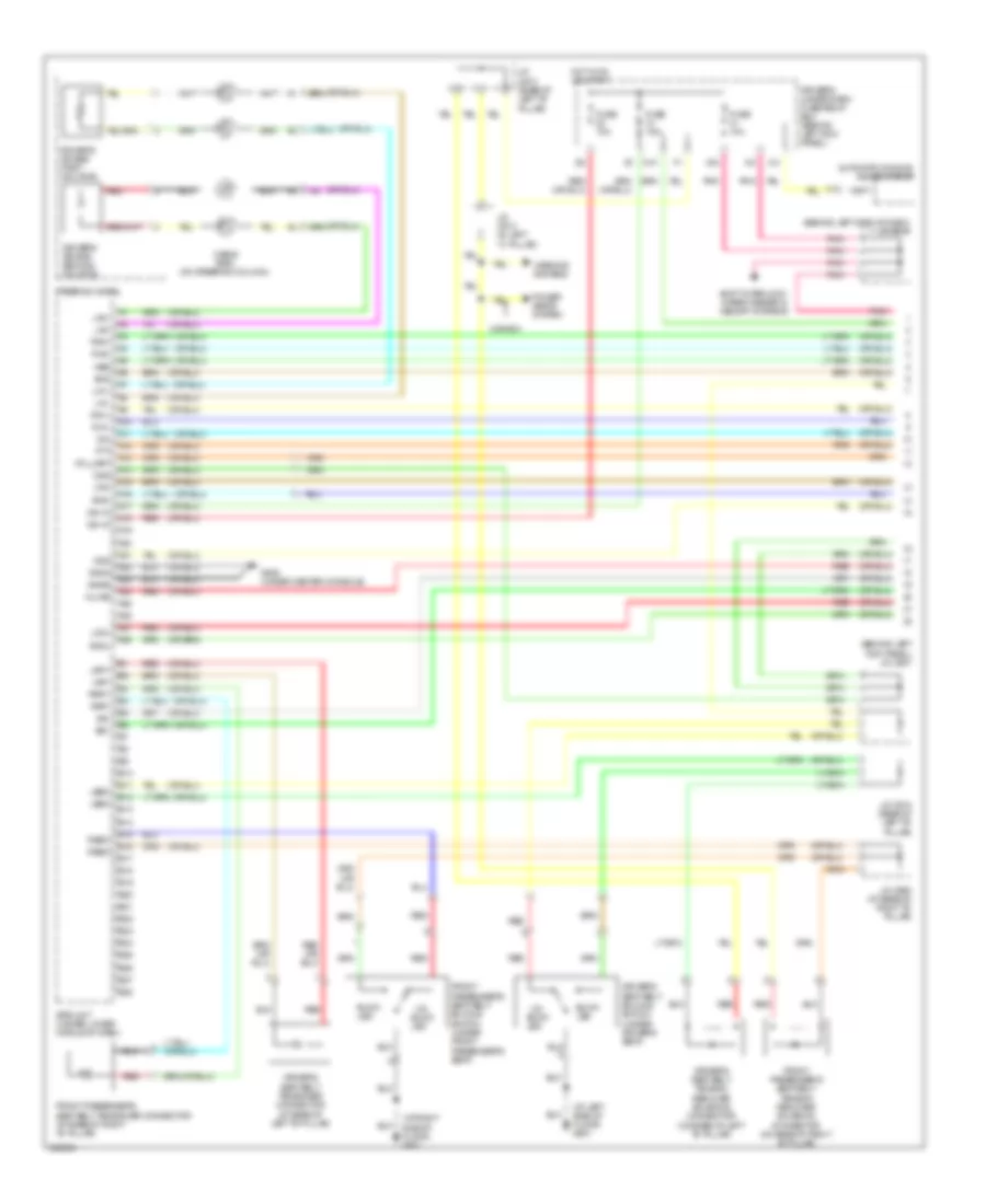
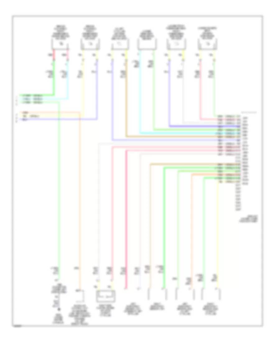
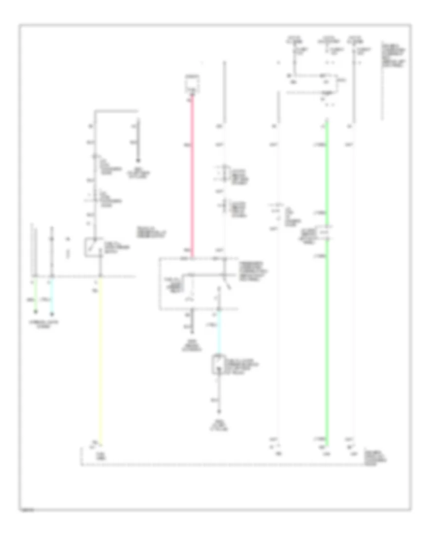
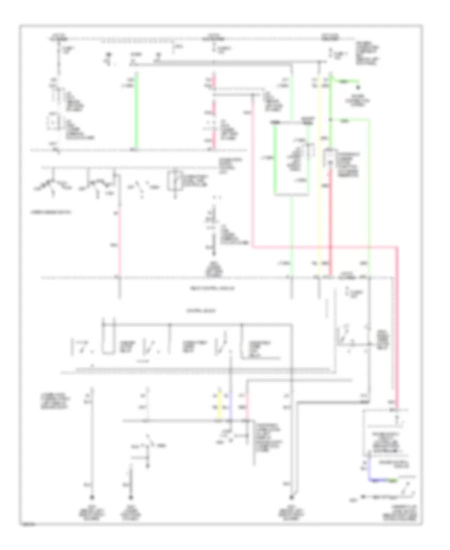
Automatic A/C Wiring Diagram (2 of 3) for Acura RL 2010
List of elements for Automatic A/C Wiring Diagram (2 of 3) for Acura RL 2010:
- 5v gnd
- A/c compressor clutch relay
- Ac-clk
- Ac-si
- Ac-so
- Acc
- Acc cut relay
- Audio unit
- Audio-hvac sub display unit clock
- B10
- B12
- B13
- B14
- B15
- B16
- B20
- B21
- B23
- B25
- B26
- B28
- B29
- B30
- B31
- B32
- Blank
- Blower motor relay
- Bus ic
- C10
- Clock
- Computer data lines system
- Data
- Driver's air mix control motor (below left side of dash)
- Driver's auxiliary under-dash relay box (under left side of dash)
- Driver's cool vent control motor (under left side of dash)
- E15
- Ecu bus (+)
- Ecu bus (-)
- F10
- Front passenger's air mix control motor (behind right side of dash)
- Front passenger's cool vent control motor (behind right side of dash)
- Fuse 12 7.5a
- Fuse 21 40a
- G301 (behind left side of front bumper)
- G506 (behind glove box)
- Ga-net (+)
- Ga-net (-)
- Ga-net shld
- Gnd
- Hot at all times
- Ic bus
- Interface dial
- J/c c508 (behind left side of dash)
- J/c c527
- Jog
- Jog shld
- Lcd bl +
- Lcd bl -
- Load
- Mode control motor (under left side of dash)
- Mt1
- Mt2
- Navigation unit (in trunk, below left side of package tray)
- Nca
- Pnk
- Rear vent control motor (under middle of dash)
- Recirculation control motor
- Red
- Seg test
- Sh ecu bus
- Shield
- Shift interlock system
- Shld
- Sig a
- Sig b
- Under-hood fuse/relay box (left rear of engine compt)
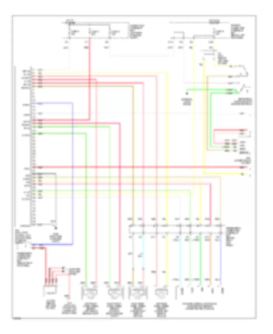
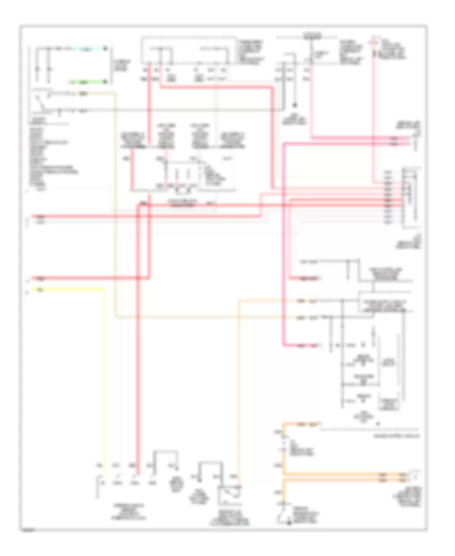
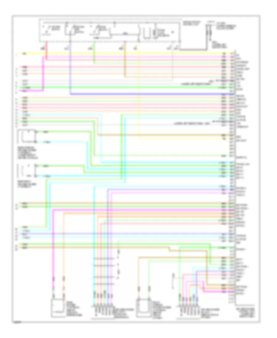
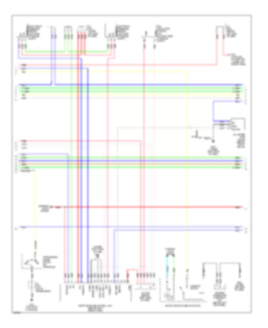
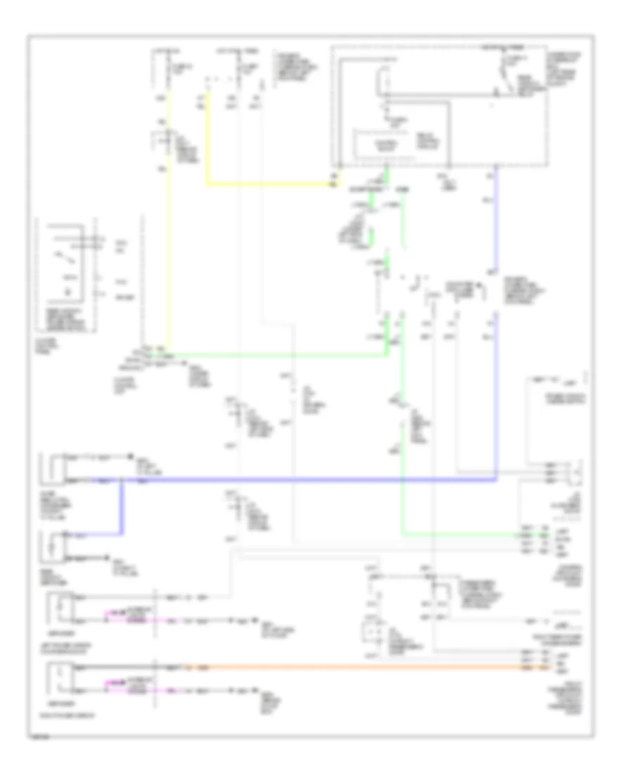
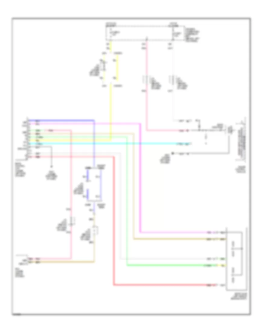
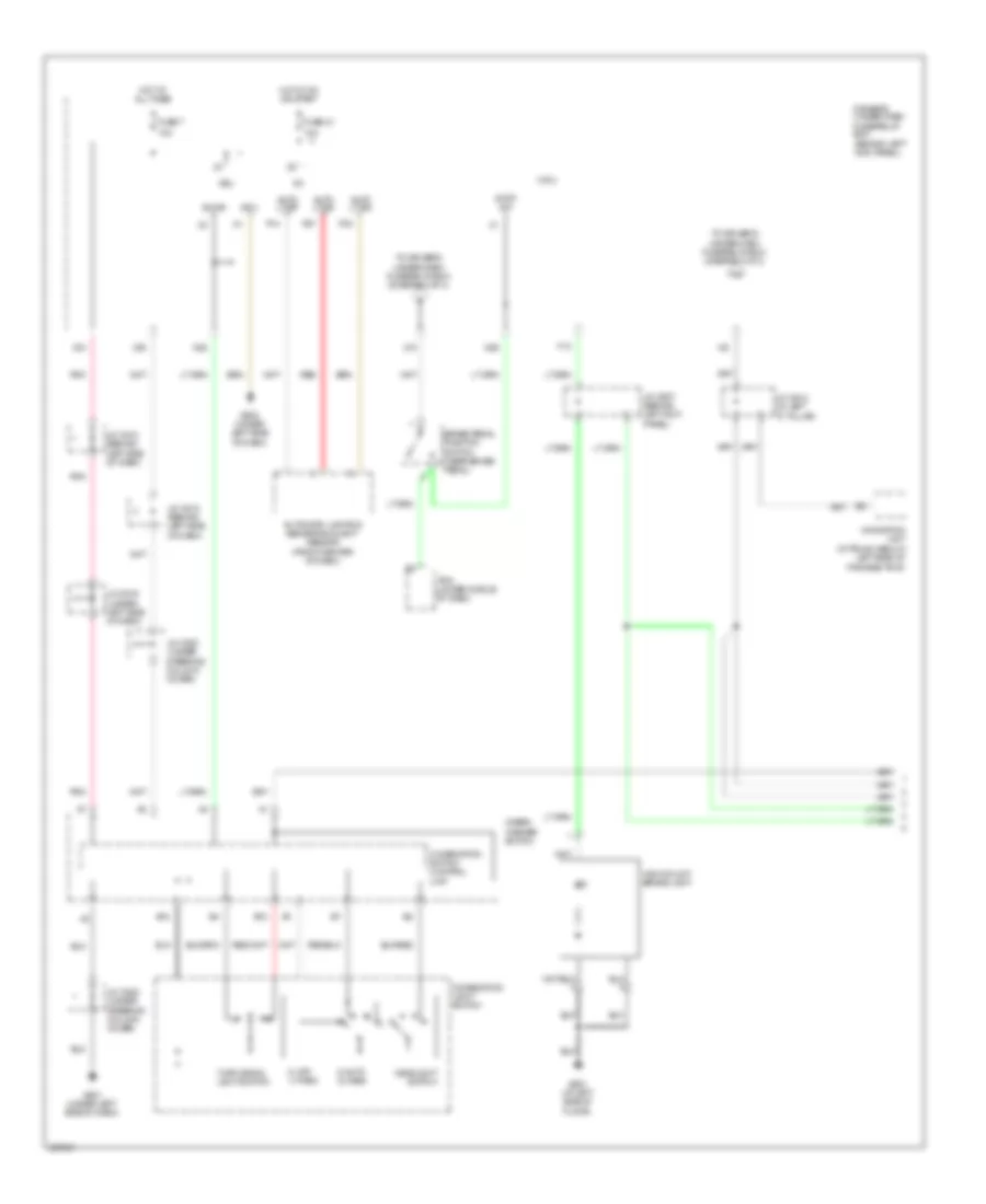
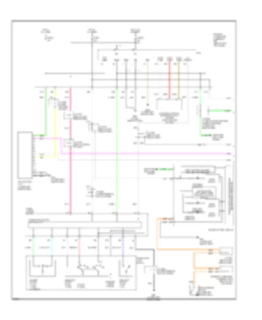
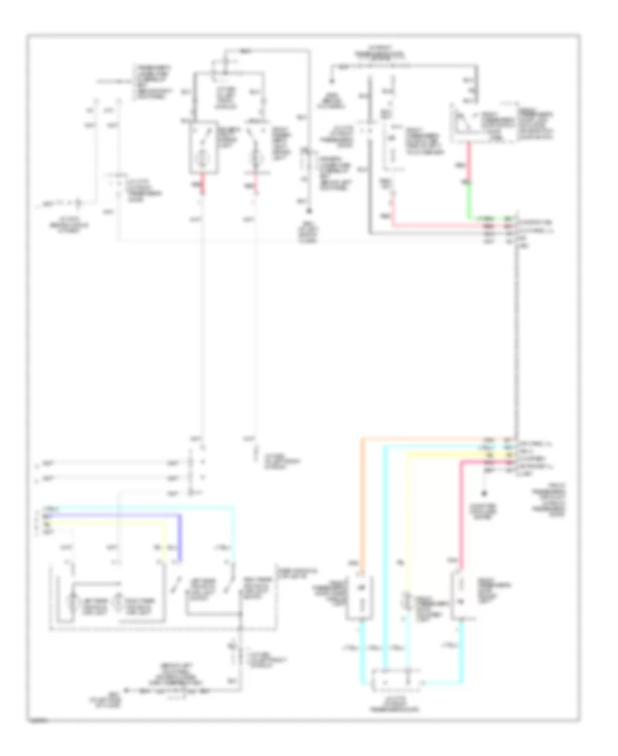
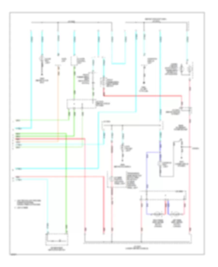
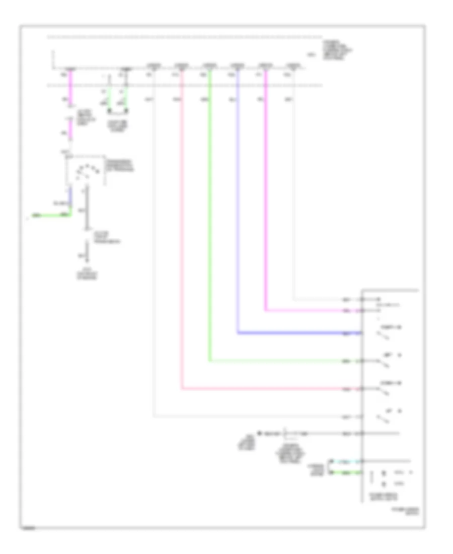
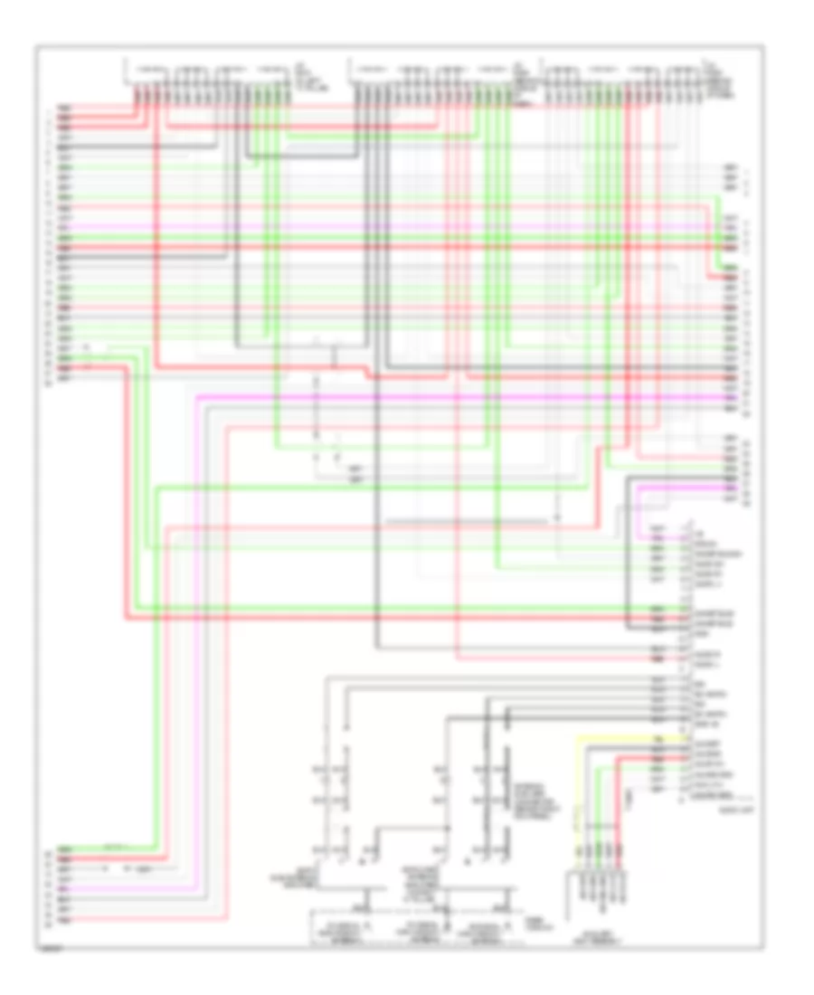
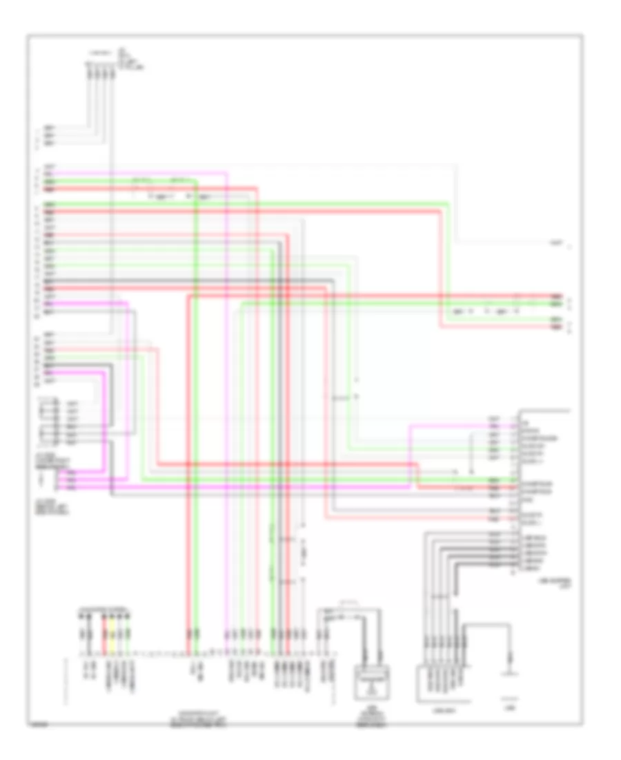
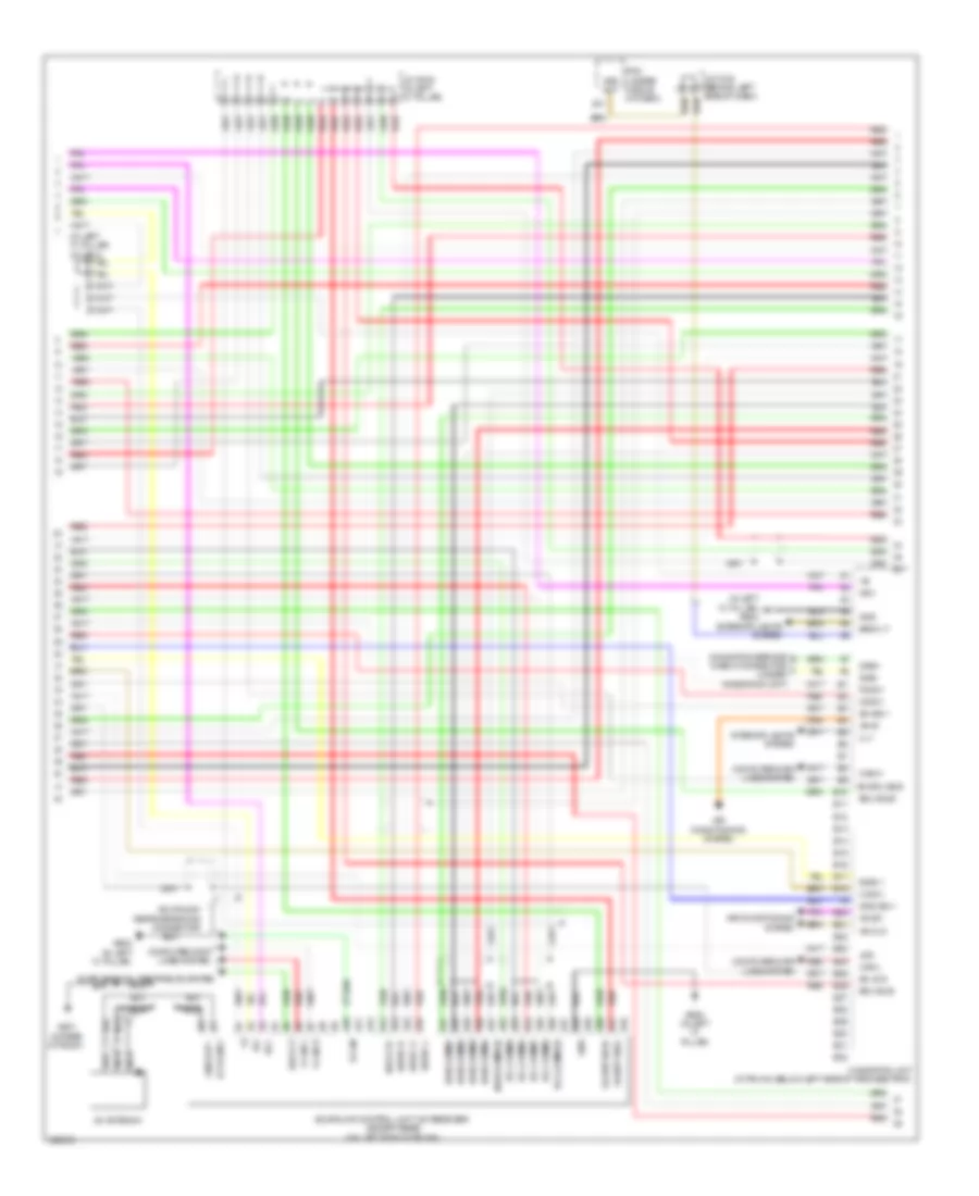
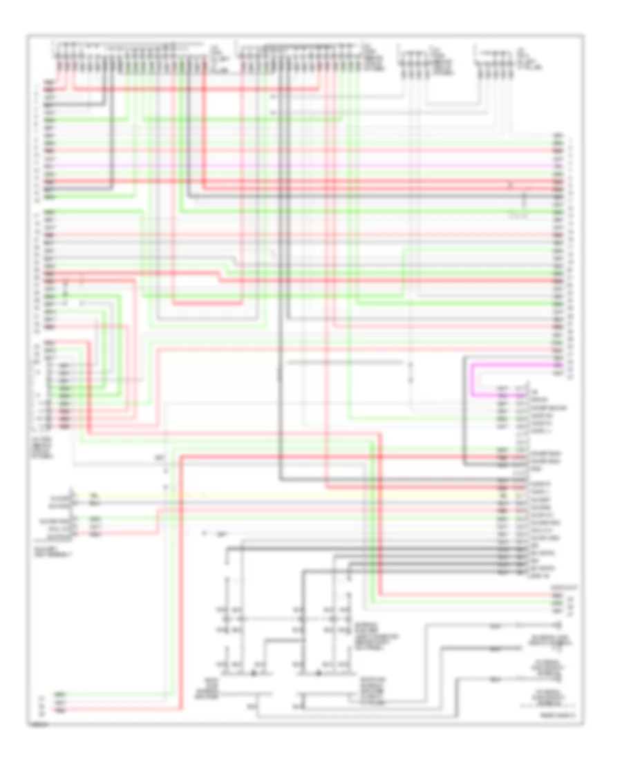
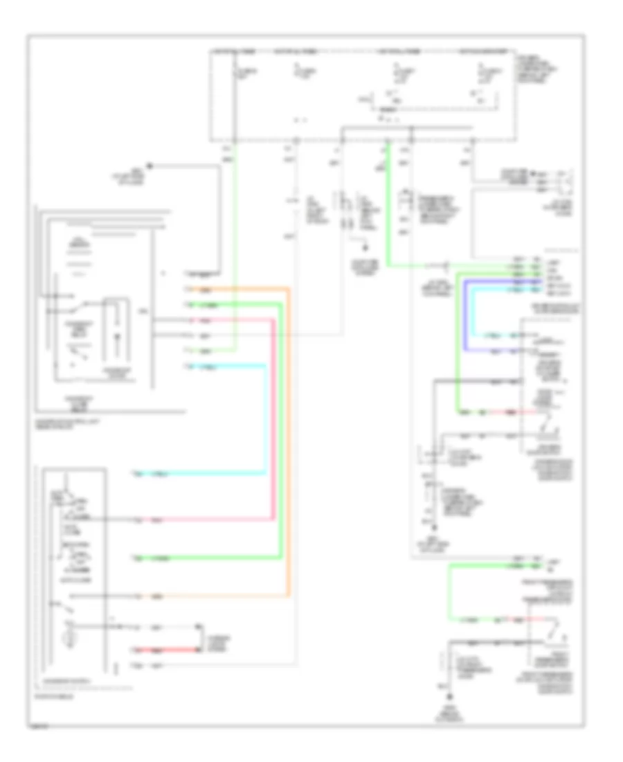
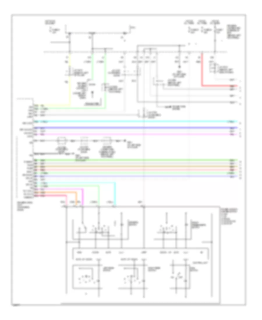
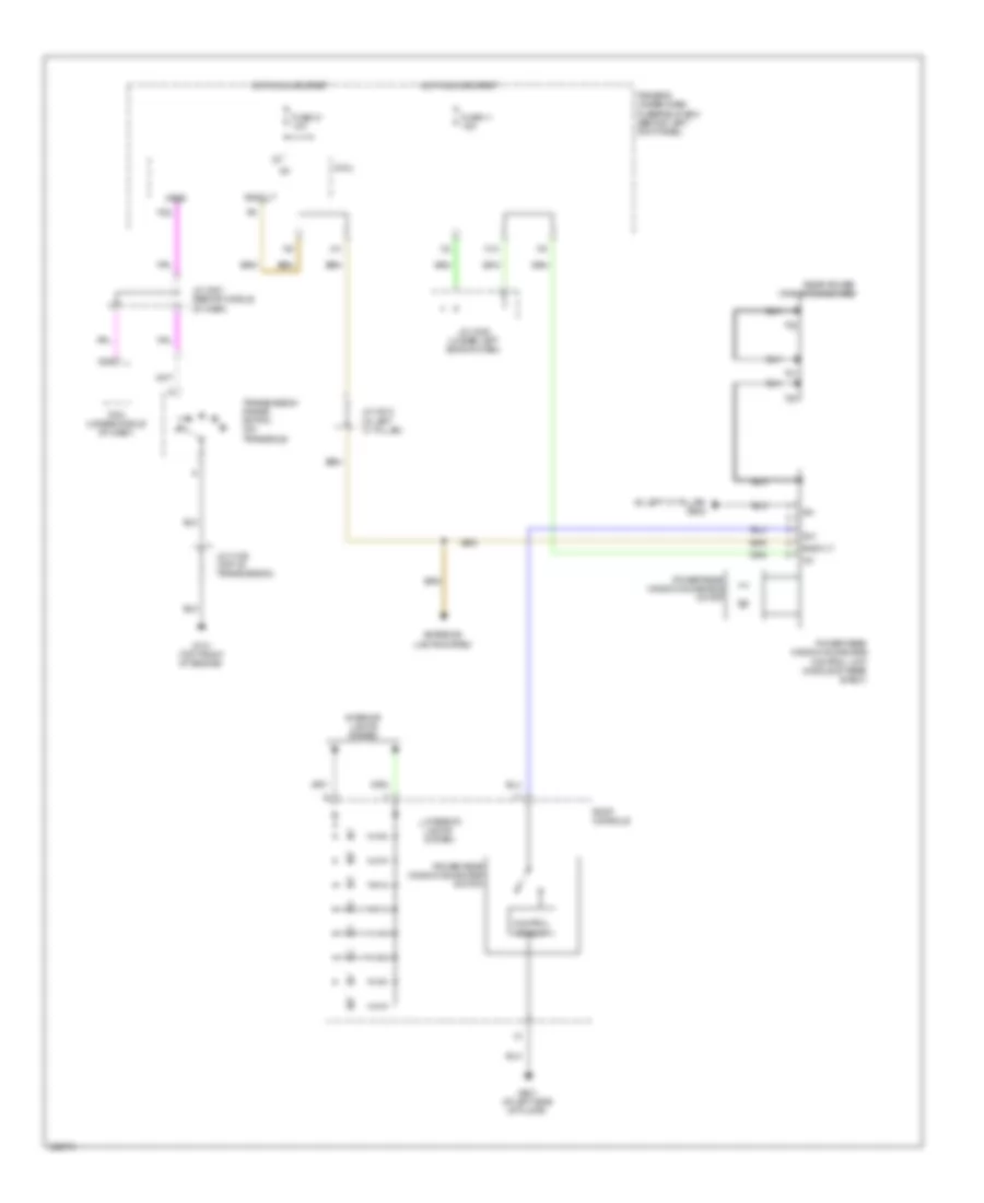
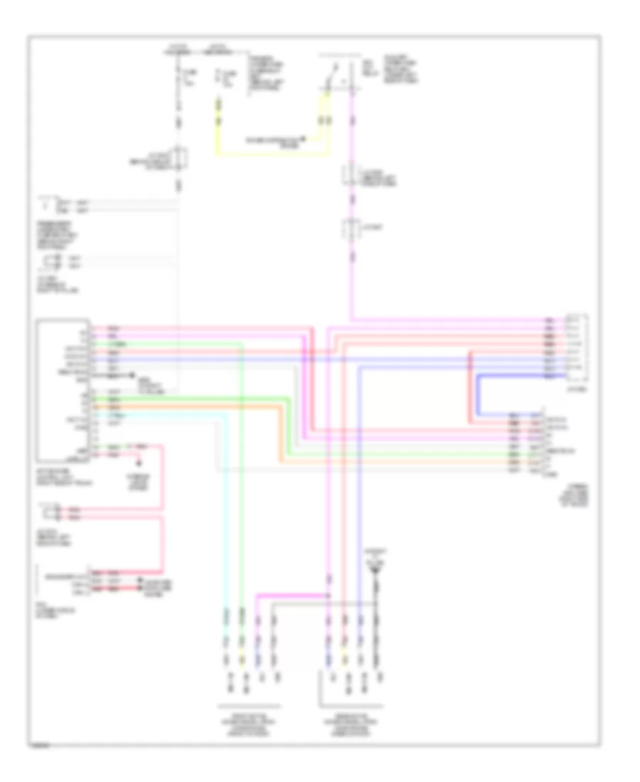
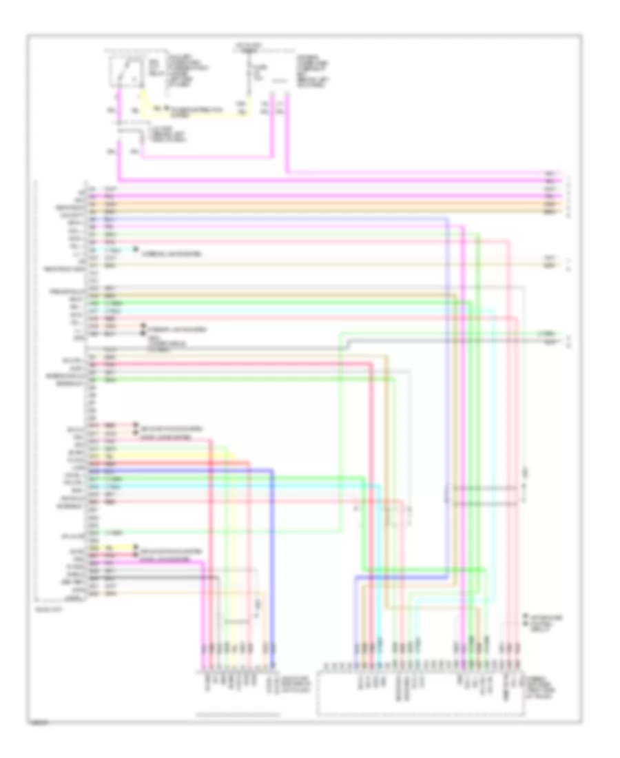
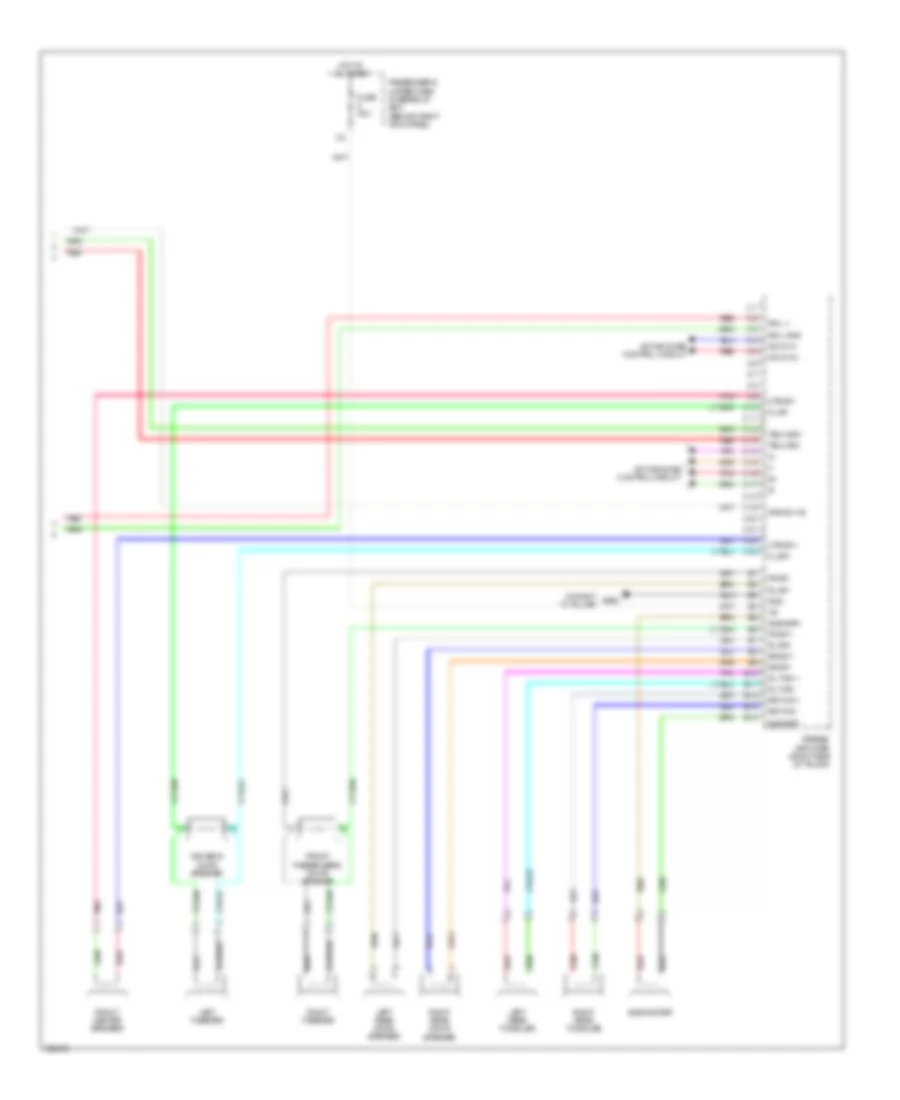
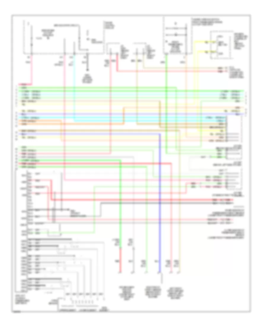
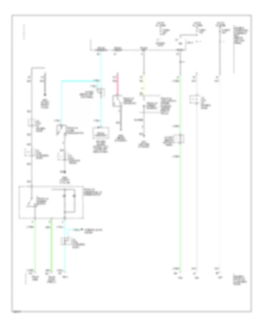
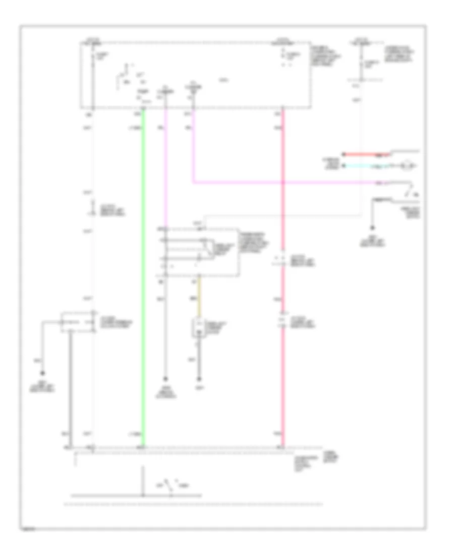
Automatic A/C Wiring Diagram (3 of 3) for Acura RL 2010
List of elements for Automatic A/C Wiring Diagram (3 of 3) for Acura RL 2010:
- A/c condenser fan motor (behind radiator)
- A13
- A14
- Acc
- Auto
- Auto climate control switch
- Auxiliary under-hood relay box (left side of engine compt)
- B24
- Battery terminal fuse box (+) (in battery terminal fuse box)
- C12
- Can-h
- Can-l
- Climate control off switch
- Climate control panel
- Climate control unit
- Computer data lines system
- Cool
- D10
- D15
- D16
- Def
- Defrost switch
- Di0
- Di1
- Di2
- Di3
- Do0
- Do1
- Do2
- Drive circuit
- Driver's temperature switch
- Driver's under-dash fuse/relay box (behind left kick panel)
- Dual zone climate control switch
- E15
- E26
- E27
- Ect sensor 1 (on top left side of engine)
- Ect sensor 2 (under left side of engine compt)
- Ect1
- Ect2
- Front passenger's temperature switch
- Fuse 23 7.5a
- Fuse 32 10a
- Fuse 34 50a
- Fuse 8 15a
- G301 (behind left side of front bumper)
- Hot at all times
- Hot in acc or on
- Ill
- J/c c108 (top of transmission)
- J/c c509 (behind left side of dash)
- Mrly
- N36
- P-ig
- Pcm (under middle of dash)
- Pgm-fi main relay 1
- Radiator fan motor (behind radiator)
- Rear window defogger/ power mirror heater switch
- Rec
- Recirculate switch
- Red
- Rfc
- Rfc rly
- Rfc unit (front middle of engine compt)
- Rfc unit relay
- Rr def
- Sg2
- Sg4
- Under- hood fuse/ relay box (left rear of engine compt)
- Warm
- X11
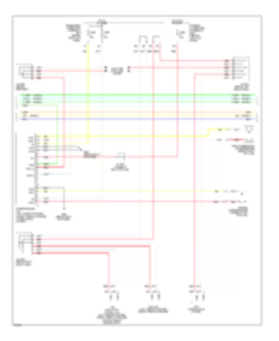
ANTI-LOCK BRAKES
Anti-lock Brakes Wiring Diagram (1 of 2) for Acura RL 2010
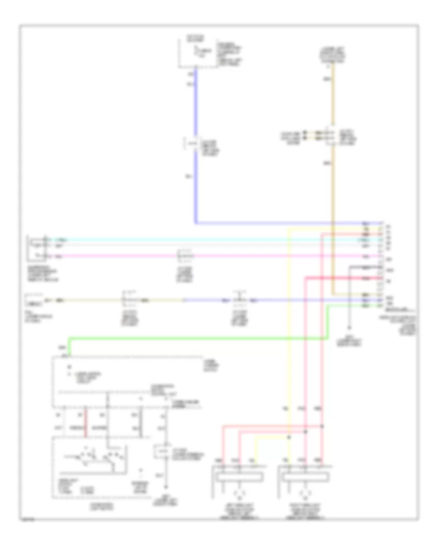
List of elements for Anti-lock Brakes Wiring Diagram (1 of 2) for Acura RL 2010:
- Bksw
- Bkswnc
- Brake pedal position switch (near brake pedal)
- Can-h
- Can-l
- Canh
- Canl
- Computer data lines system
- D10
- D13
- Diag-k
- Dlc (data link connector) (under left side of dash)
- Driver's under-dash fuse/relay box (behind left kick panel)
- E15
- E26
- Exterior lights system
- Fl +b
- Fl-gnd
- Fr +b
- Fr-gnd
- Fsr +b
- Fuse 13 15a
- Fuse 17 30a
- Fuse 18 15a
- Fuse 18 40a
- G lat
- G long
- G13
- G202 (right side of engine compt)
- Glat
- Glong
- Gnd
- Hot at all times
- Hot in on or start
- Ig1
- J/c c508 (behind left side of dash)
- J/c c510 (behind left side of dash)
- J10
- J12
- J13
- Left front wheel speed sensor (left side of engine compt)
- Left rear wheel speed sensor (under left rear of vehicle)
- Mr +b
- Mtr gnd
- N29
- Passenger's under-dash fuse/relay box (behind right kick panel)
- Pcm (under middle of dash)
- Pnk
- Red
- Right front wheel speed sensor (on right side of engine compt)
- Right rear wheel speed sensor (under right rear of vehicle)
- Rl +b
- Rl-gnd
- Rr +b
- Rr-gnd
- S-gnd
- Sgnd
- Svcc
- Under-hood fuse/relay box (left rear of engine compt)
- Vsa modulator control unit (on right side of engine compt)
- X10
- Yaw
- Yaw rate-lateral/longitudinal acceleration sensor (under center console)
Anti-lock Brakes Wiring Diagram (2 of 2) for Acura RL 2010
List of elements for Anti-lock Brakes Wiring Diagram (2 of 2) for Acura RL 2010:
- (behind left side of dash) j/c c510
- (not used)
- Abs ind
- Afs off/ vsa off switch (usa: w/ technology package) afs off/ vsa off/ cmbs off switch (usa: cmbs/pax package, canada: premium package) vsa off switch (w/ base)
- B10
- B12
- B13
- B14
- B15
- B16
- Brake fluid level switch (integral to brake fluid reservoir cap)
- Brake system ind
- Canh
- Canl
- Computer data lines system
- Dlc (data link connector) (under left side of dash)
- Drive circuit
- Driver's under-dash fuse/relay box (behind left kick panel)
- Fast controller area network transceiver
- Fuse 21 10a
- G401 (under right side of dash)
- G501 (under left side of dash)
- G506 (behind glove box)
- Gauge control module
- Gnd
- Hot in on or start
- Ig1
- Interior lights system
- J/c c202 (behind right side of dash)
- J/c c507 (behind left side of dash)
- J/c c518 (behind left side of dash)
- N21
- N30
- N34
- N37
- Parking brake switch (under left side of dash)
- Passenger's under-dash fuse/relay box (behind right kick panel)
- Pnk
- Red
- Steering angle sensor (on side of steering column)
- Usa: base, w/ technology package canada: base
- Usa: cmbs/ pax package canada: premium package
- Vsa activation ind
- Vsa off switch
- Vsa system ind
- Warning drive circuit
- X34
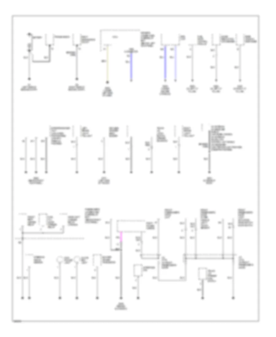
ANTI-THEFT
Forced Entry Wiring Diagram (1 of 5) for Acura RL 2010
List of elements for Forced Entry Wiring Diagram (1 of 5) for Acura RL 2010:
- (at left side of floor) g601
- (behind left side of dash) j/c c510
- (behind left side of dash) j/c c512
- (not used)
- (under left side of dash)
- +b door lock
- A21
- Acc
- Acc & cut relay
- Atpp
- Auxiliary under-dash relay box (under left side of dash)
- B-can
- B10
- B14
- B17
- B28
- Body controller area network transceiver
- Brake system indicator
- Cds
- D11
- Dr un l
- Driver's door lock actuator/ knob switch/ door switch
- Driver's under-dash fuse/relay box (behind left kick panel)
- E10
- Front passenger's door lock actuator/ knob switch/ door switch
- Fuse 10a
- Fuse 20a
- G101 (top front of engine)
- G501
- G502 (under left side of dash)
- G701 (left side of trunk)
- Gauge control module
- H10
- Hot at all times
- Hot in acc or on
- Hot in on or start
- Ig key sw
- Ig1
- Immobilizer system indicator
- J/c c106 (top of transmission)
- J/c c521 (behind middle of dash)
- J/c c522 (behind middle of dash)
- J/c c610 (base of left "b" pillar)
- J/c c757 (in driver's door)
- K11
- K12
- Keyless access system indicator
- Keyless answer back buzzer (behind middle of rear bumper)
- Keyless buzzer
- Left rear door lock actuator/ knob switch/ door switch (rear of left rear door)
- Lock
- Micu
- N22
- N36
- P13
- P16
- P21
- P29
- Pnk
- Red
- Right rear door lock actuator/ knob switch/ door switch (rear of right rear door)
- Seats system
- Security indicator
- Security indicator blinking circuit
- Sg1
- Sg2
- Shift interlock system
- Srs unit (under lower middle of dash)
- Starting/charging system
- Transmission range switch (on transaxle)
- Transmissions system
- Trunk act
- Trunk hndl sw
- Trunk switch
- Trunk, tailgate, fuel doors system
- Un l
- Vbu
- X18
- X34
- X35
Forced Entry Wiring Diagram (2 of 5) for Acura RL 2010
List of elements for Forced Entry Wiring Diagram (2 of 5) for Acura RL 2010:
- (in driver's door)
- (under right side of dash) g401
- A21
- A22
- A23
- A24
- A25
- A27
- A28
- A37
- B14
- Base
- Can
- Computer data lines system
- Control block
- Dr sw
- Driver's door key cylinder switch
- Driver's door lock actuator/ knob switch/ door switch
- Driver's door lock knob switch
- Driver's door lock switch
- Driver's door switch
- Driver's mpcs unit (in driver's door)
- Driver's under-dash fuse/relay box (behind left kick panel)
- Except base
- Fuse 13 15a
- Fuse 6 7.5a
- G601 (at left side of floor)
- High horn (behind middle of front bumper)
- Horn relay
- Hot at all times
- Ign
- Ill out handl
- Interior lights system
- J/c c305 (under left side of dash)
- J/c c508 (behind left side of dash)
- J/c c514 (under left side of dash)
- J/c c609 (behind left kick panel)
- J/c c755 (in driver's door)
- J/c c756
- J/c c757 (in driver's door)
- J/c c783 (in left rear door)
- J/c c793 (in right rear door)
- Key lock
- Key unlck
- Left rear door lock actuator/ knob switch/ door switch (rear of left rear door)
- Left rear door lock knob switch
- Left rear door switch
- Left rear power window switch
- Lock
- Low horn (behind middle of front bumper)
- N15
- Pnk
- Power tops system
- Power windows system
- Red
- Relay control module
- Remote ill
- Security hood switch (behind middle of front bumper)
- Sgnd
- Trunk, tail- gate & fuel doors system
- Uart
- Under-hood fuse/relay box (left rear of engine compt)
- Unlock
- Vbu
- Vbu 2
- X15
Forced Entry Wiring Diagram (3 of 5) for Acura RL 2010
List of elements for Forced Entry Wiring Diagram (3 of 5) for Acura RL 2010:
- (in front passenger's door)
- A10
- A15
- A16
- A17
- A20
- A23
- A26
- A28
- As dr sw
- B14
- Control block
- D13
- Diag-h
- Dlc (under left side of dash)
- Dr sw
- E13
- E25
- Front passenger's door lock actuator/ knob switch/ door switch
- Front passenger's door lock knob switch
- Front passenger's door lock switch
- Front passenger's door switch
- Front passenger's mpcs unit (in front passenger's door)
- G14
- G506 (behind glove box)
- G651 (at right side of floor)
- Headlights system
- Ill (+)
- Immobilizer control unit- receiver (on right side of steering column)
- Immocont
- Imocd
- Imoes unit (under middle of dash)
- Imolmp
- J/c c507 (behind left side of dash)
- J/c c511 (behind left side of dash)
- J/c c513 (behind left side of dash)
- J/c c775 (in front passenger's door)
- J/c c776
- J/c c793 (in right rear door)
- Key out
- Lock
- Passenger's under-dash fuse/relay box (behind right kick panel)
- Pcm (under middle of dash)
- Pnk
- Red
- Remote ill
- Right rear door lock actuator/ knob switch/ door switch (rear of right rear door)
- Right rear door lock knob switch
- Right rear door switch
- Right rear power window switch
- S-net
- Sgnd
- Uart
- Unlck
- Unlock
- Vbu
- Vbu 1
Forced Entry Wiring Diagram (4 of 5) for Acura RL 2010
List of elements for Forced Entry Wiring Diagram (4 of 5) for Acura RL 2010:
- (in front passenger's door) j/c c775
- Audio unit
- B11
- B27
- Driver's door lf antenna
- Driver's door outer handle light/ touch sensor (center of driver's door)
- Driver's under-dash fuse/relay box (behind left kick panel)
- Front passenger's door lf antenna
- Front passenger's door outer handle light/ touch sensor (center of front passenger's door)
- Fuse 20a
- G506 (behind glove box)
- G601 (at left side of floor)
- G652 (in right "c" pillar)
- Hot in on or start
- Immobilizer circuit
- Ims1
- Ims2
- J/c c507 (behind left side of dash)
- J/c c757 (in driver's door)
- J/c c833 (middle of trunk)
- N30
- N34
- Outer handle touch sensor/ door lock button
- Parking brake switch (under left side of dash)
- Pnk
- Red
- Trunk lid outer handle switch
Forced Entry Wiring Diagram (5 of 5) for Acura RL 2010
List of elements for Forced Entry Wiring Diagram (5 of 5) for Acura RL 2010:
- (under left side of dash)
- + b1
- +b backup
- A10
- A11
- A12
- A13
- A14
- A15
- A16
- A17
- A18
- A19
- A20
- A21
- A22
- A23
- A24
- A25
- A26
- A27
- A28
- A29
- A30
- A31
- Acc
- B can
- B10
- B11
- B12
- B13
- B14
- B15
- B16
- B17
- B18
- B19
- B20
- B21
- B22
- B23
- B24
- C10
- C11
- C12
- C13
- C14
- C15
- C16
- C17
- Cpu
- Diag h
- Dl fr as
- Dl fr dr
- Ext f +
- Ext f -
- Ext fr as +
- Ext fr as -
- Ext fr dr +
- Ext fr dr -
- Ext r +
- Ext r -
- Ext ti +
- Ext ti -
- Ext tr +
- Ext tr -
- Front interior keyless access lf antenna (behind middle of dash)
- G501
- G501 (under left side of dash)
- Hbrk sw
- Ig1
- Ign cont
- Ign trx
- Ignition key switch
- Ignition switch control unit
- Immobi lamp
- Immocont
- Ims1
- Ims2
- J/c c520 (under steering column cover)
- Key out
- Key sw
- Keyless access control unit (under left side of dash)
- Keyless access rf unit 1 (behind middle of dash)
- Keyless access rf unit 2 (middle of rear shelf)
- Knob lock solenoid
- Knob sw
- Knob switch
- Lg1
- Lg2
- Pnk
- Rear bumper lf antenna (behind middle of rear bumper)
- Rear interior keyless access lf antenna (under rear of center console)
- Rear shelf keyless access lf antenna
- Red
- Rf gnd 1
- Rf gnd 2
- Rf gnd1
- Rf gnd2
- Rfrxd 1
- Rfrxd 2
- Rfrxd1
- Rfrxd2
- Rftxd 1
- Rftxd 2
- Rftxd1
- Rftxd2
- Rotate sw
- Rotate switch
- Rssi 1
- Rssi 2
- Rssi1
- Rssi2
- Rxvcc 1
- Rxvcc 2
- Rxvcc1
- Rxvcc2
- S net
- Scs
- Sg1
- Sg2
- Smart mil
- Tr hndl sw
- Ts fr as
- Ts fr dr
- Txvcc 1
- Txvcc 2
- Txvcc1
- Txvcc2
Immobilizer Wiring Diagram for Acura RL 2010
List of elements for Immobilizer Wiring Diagram for Acura RL 2010:
- A15
- A16
- Anti-theft circuit
- B15
- B16
- B28
- Computer data lines system
- Diag h
- Diag-h
- Dlc (under left side of dash)
- Driver's under-dash fuse/relay box (behind left kick panel)
- E13
- E20
- E25
- Engine controls system
- Fp+
- Fp-
- Fpc
- Fpcd
- Fuel pump
- Fuel pump control module (in left "c" pillar)
- Fuel tank unit (under left side of rear seat)
- Fuse 10a
- Fuse 20a
- G101 (left side of engine)
- G603 (in left "c" pillar)
- Gauge control module
- H/brake sw
- Hot at all times
- Hot in on or start
- Ig1
- Igp
- Immobi alrm
- Immobilizer control unit- receiver (on right side of steering column)
- Immobilizer system indicator
- Immocont
- Imocd
- Imoes unit (under middle of dash)
- Imofpr
- Imolmp
- J/c c507 (behind left side of dash)
- J/c c511 (behind left side of dash)
- J/c c512 (behind left side of dash)
- J/c c513 (behind left side of dash)
- J/c c515 (behind middle of dash)
- J/c c517 (behind middle of dash)
- J/c c520 (under steering column cover)
- Key out
- Keyless access control unit (under left side of dash)
- Lg1
- Lg2
- Micu
- Mrly
- N30
- N34
- Network transceiver fast controller area
- P13
- Parking brake switch (under left side of dash)
- Pcm (under middle of dash)
- Pgm-fi main relay 1
- Pgm-fi main relay 2
- Pnk
- Red
- S net
- S-net
- X31
- X35
- X38
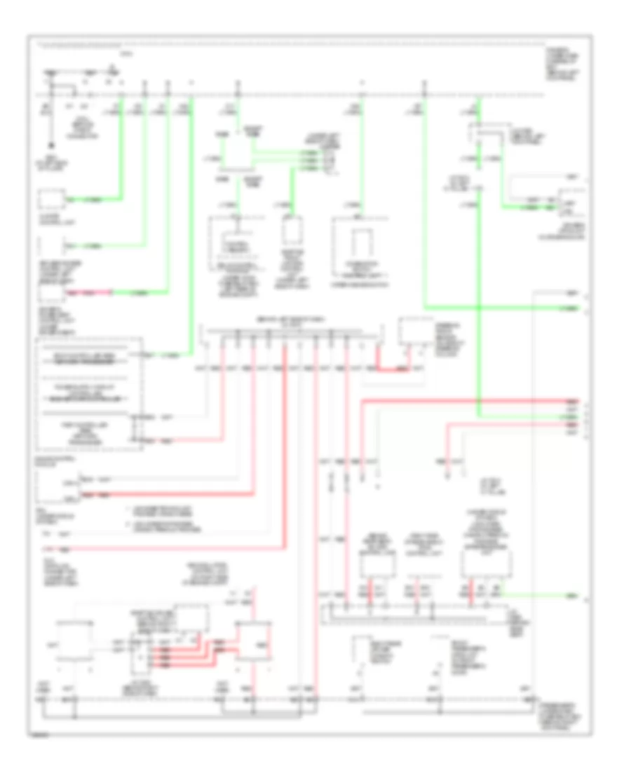
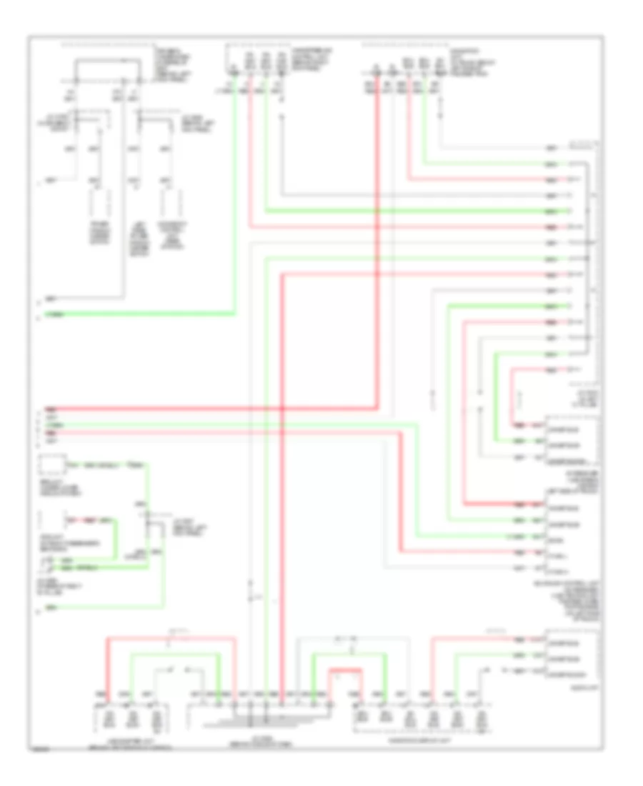
BODY CONTROL MODULES
Body Control Modules Wiring Diagram for Acura RL 2010
List of elements for Body Control Modules Wiring Diagram for Acura RL 2010:
- (at left side of floor)
- (at left side of floor) g601
- (not used)
- +b door lock
- Acc
- Atp-p
- Atp-r
- Auto lt sid
- Auto lt sig
- Auto lt sip
- B-can
- Back lt
- Cds
- Chk
- Computer data lines system
- D/l mtr (dn un l)
- D/l mtr (lock)
- D/l mtr (un l)
- D11
- Dlc
- Door locks & anti-theft systems
- Driver's under-dash fuse/relay box (behind left kick panel)
- E10
- E14
- Exterior lights system
- F12
- F14
- Foot lt
- Fuel lid
- Fuse 10a
- Fuse 20a
- Fuse 7.5a
- G502 (under left side of dash)
- G601
- Gnd
- H/l backup
- H/l clean sw
- H/l cleaner
- H10
- H14
- Hazard sw
- Headlights system
- Hot at all times
- Hot in acc or on
- Hot in on
- Hot in on or start
- Ig key sw
- Ig1
- Ig2
- Interior lights system
- Intr lt
- J14
- K11
- K12
- Key lt
- Key sol
- Keyless buzzer
- Map lt off
- Memory systems
- Micu
- Micu service check connector
- Mirror dn
- Mirror l
- Mirror lt
- Mirror r
- Mirror rt
- Mirror up
- N22
- N26
- N28
- N38
- N44
- P-pin
- P10
- P11
- P12
- P13
- P14
- P15
- P16
- P17
- P18
- P19
- P20
- P21
- P22
- P23
- P24
- P25
- P26
- P27
- P28
- P29
- P30
- Pnk
- Q10
- Q11
- Q12
- Q13
- Q14
- Radio sw
- Red
- Seat belt sw
- Sg-1
- Sg-2
- Shift interlock system
- Sound systems
- Stop sw
- Transmissions system
- Trunk act
- Trunk handle sw
- Trunk main sw
- Trunk sw
- Trunk, tailgate, fuel doors system
- Trunk, tailgate, fuel doors system door locks & trunk, tailgate, fuel doors systems interior lights system
- Turn signal/ hazard relay 1
- Turn sw l
- Turn sw r
- Vbu
- Warning systems
- Wiper/washer system
- X13
- X18
- X27
COMPUTER DATA LINES
Data Link Connector Wiring Diagram for Acura RL 2010
List of elements for Data Link Connector Wiring Diagram for Acura RL 2010:
- (behind left side of dash) j/c c513
- A15
- A24
- A25
- Adaptive cruise control unit (usa: cmbs/pax package) (canada: premium package) (behind right side dash)
- Adaptive front lighting control unit (under left side of dash)
- Base
- Diag +
- Diag -
- Diag-h
- Dlc (data link connector) (under left side of dash)
- Driver's under-dash fuse/relay box (behind left kick panel)
- E16
- E24
- Except base
- Fuse 7 10a
- G501 (under left side of dash)
- G505 (under center console)
- Headlight leveling control unit (under left side of dash)
- High/low bus circuit
- Hot at all times
- Immobilizer control unit receiver (on right side of steering column)
- J/c c508 (behind left side of dash)
- J/c c511 (behind left side of dash)
- J/c c512 (behind left side of dash)
- J/c c522 (behind middle of dash)
- J/c c661 (at base of left "b" pillar)
- K-line
- Keyless access control unit (under left side of dash)
- Mes
- Mes connector
- Micu
- Navigation service check connector (under navigation unit)
- Navigation unit (in trunk, below left side of package tray)
- Passenger's under-dash fuse/relay box (behind right kick panel)
- Pcm (under middle of dash)
- Red
- Scs
- Sh-awd control unit (behind rear seat)
- Srs unit (under lower middle of dash)
- Tpms control unit (right side of rear shelf)
- Vsa modulator control unit (on right side of engine compt)
- Wen
- X35
High/Low Bus Wiring Diagram (1 of 2) for Acura RL 2010
List of elements for High/Low Bus Wiring Diagram (1 of 2) for Acura RL 2010:
- (behind left side of dash) j/c c518
- (behind rear seat) sh-awd control unit
- (not used)
- (on right side of engine compt)
- (right side of rear shelf) tpms control unit
- (under left side of dash) j/c c305
- (under middle of dash) (usa: cmbs/ pax package) (canada: premium package) e-pretensioner unit
- A10
- A11
- A28
- A40
- Adaptive cruise control unit (behind right side of dash)
- Adaptive front lighting control unit (under left side of dash)
- B- can
- B10
- B15
- B16
- B17
- B19
- Base
- Body controller area network transceiver
- Can
- Can h
- Can l
- Canada: premium package
- Chk
- Climate control unit
- Combination switch control unit
- Control block
- D11
- Dlc (data link connector) (under left side of dash)
- Driver's mpcs unit (in driver's door)
- Driver's power seat control unit (under driver's seat)
- Driver's under-dash fuse/relay box (behind left kick panel)
- E13
- E15
- E26
- Except base
- Fast controller area network transceiver
- Front passenger's mpcs unit (in front passenger's door)
- G14
- G601 (at left side of floor)
- Gauge control module
- J/c c202 (behind right side of dash)
- J/c c608 (behind left kick panel)
- J/c c613 (in left "c" pillar)
- J/c c614 (in left "c" pillar)
- J/c c662 (behind rear seat)
- Keyless access control unit (under left side of dash)
- Micu
- Micu service check connector
- N22
- N28
- Package; canada: base
- Passenger's under-dash fuse/relay box (behind right kick panel)
- Pcm (under middle of dash)
- Pnk
- Red
- Relay control module
- Right rear power window switch
- Sg-2
- Steering angle sensor (on side of steering column)
- Uart
- Under-hood fuse/relay box (left rear of engine compt)
- Usa: base technology
- Usa: cmbs/pax package;
- Vsa modulator- control unit
- Wiper/washer switch
- X18
- X27
High/Low Bus Wiring Diagram (2 of 2) for Acura RL 2010
List of elements for High/Low Bus Wiring Diagram (2 of 2) for Acura RL 2010:
- A10
- A14
- A30
- A31
- Acuralink control unit (xm receiver) (usa: technology package, cmbs/ pax package) (on left side of trunk)
- Audio unit
- B- can
- B-can
- B10
- B24
- B26
- C10
- Driver's under-dash fuse/relay box (behind left kick panel)
- Ecu bus +
- Ecu bus -
- Ecu bus+
- Ecu bus-
- F-can h
- F-can l
- Ga- net bus +
- Ga- net bus -
- Ga- net bus sh
- Ga- net bus+
- Ga- net bus-
- Ga-net bus sh
- Ga-net bus+
- Ga-net bus-
- Handsfreelink control unit (behind right kick panel)
- J/c c525 (behind middle of dash)
- J/c c607 (behind left kick panel)
- J/c c609 (behind left kick panel)
- J/c c616 (in left "c" pillar)
- J/c c660 (at base of right "b" pillar)
- J/c c755 (in driver's door)
- Left rear power window master switch
- Moonroof control unit (rear of roof)
- Navigation display unit
- Navigation unit (in trunk, below left side of package tray)
- Ods unit (in front passenger's seat back)
- Power window master switch
- Red
- Sh ecu bus
- Srs unit (under lower middle of dash)
- Usb adapter unit (behind left side of glove box)
- X15
- Xm receiver (usa: base & canada) (left side of trunk)
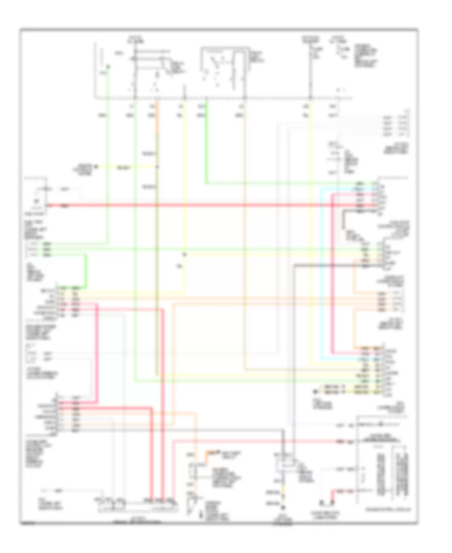
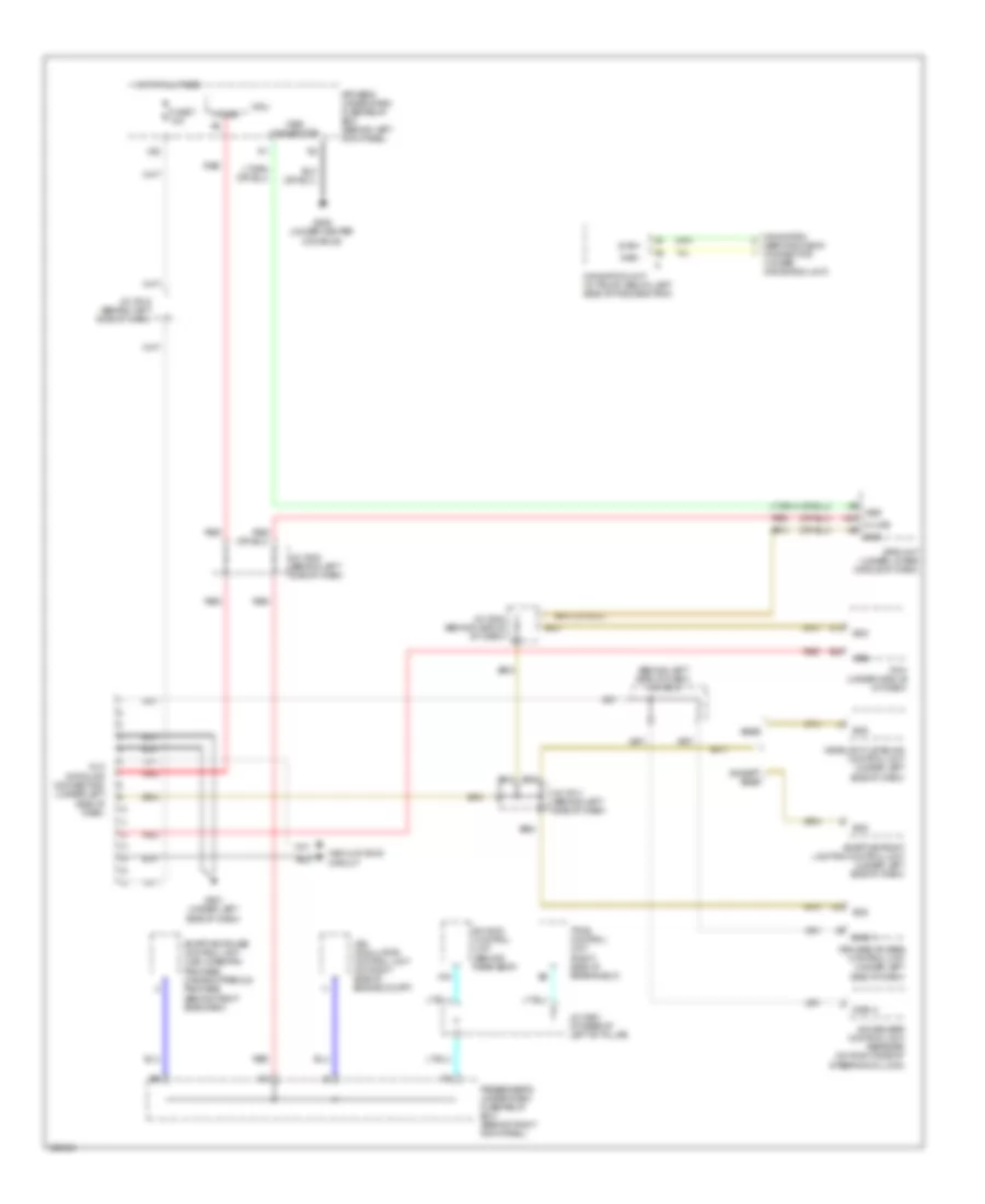
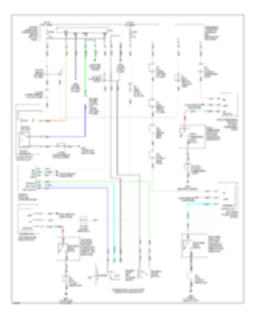
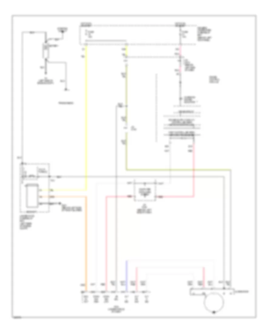
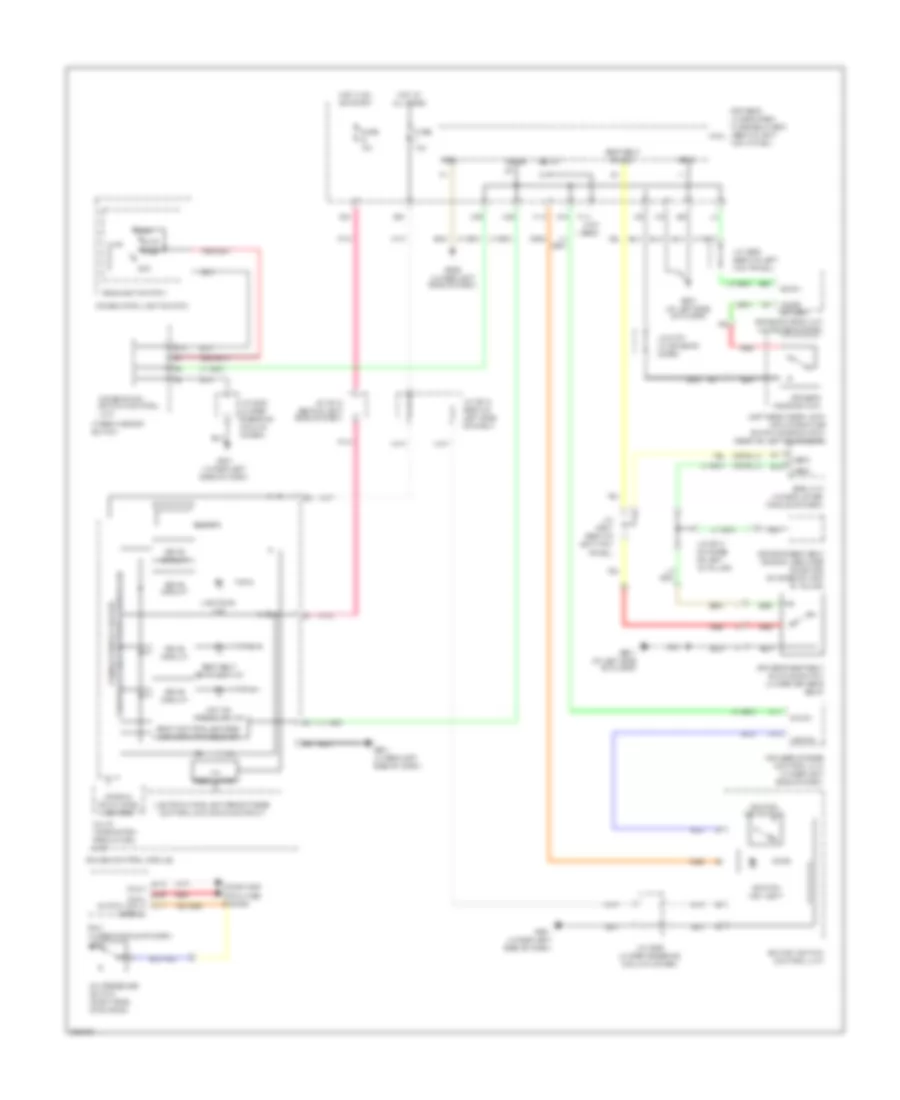
COOLING FAN
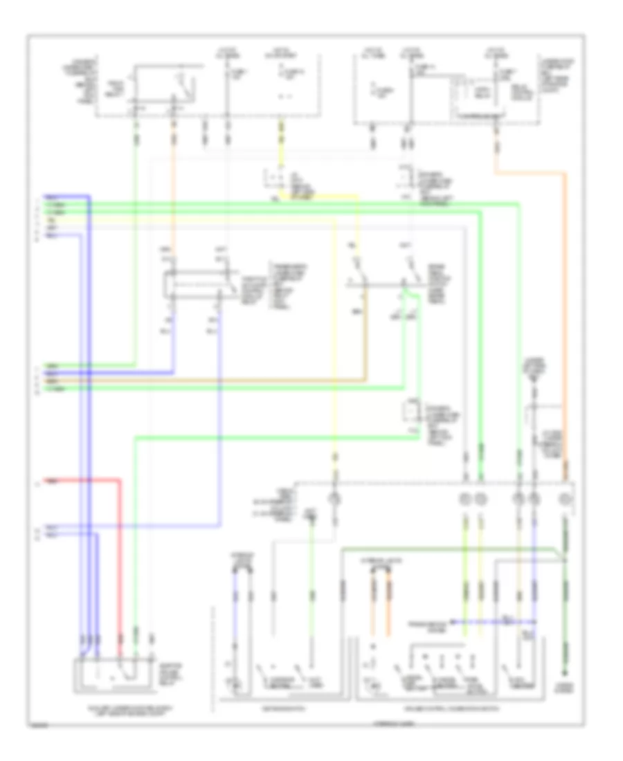
Cooling Fan Wiring Diagram for Acura RL 2010
List of elements for Cooling Fan Wiring Diagram for Acura RL 2010:
- (top of transmission)
- A/c condenser fan motor (behind radiator)
- A/c pressure sensor (right side of engine compt)
- A13
- A14
- Air conditioning system
- Auxiliary under-hood relay box (left side of engine compt)
- B-can
- B24
- Battery terminal fuse box (+) (in battery terminal fuse box)
- C12
- Canh
- Canl
- Climate control unit
- Computer data lines system
- D10
- D15
- D16
- Drive circuit
- Driver's under-dash box fuse/relay (behind left kick panel)
- Driver's under-dash fuse/relay box (behind left kick panel)
- E15
- E26
- Ect sensor 1 (on top left side of engine)
- Ect sensor 2 (under left side of engine compt)
- Ect1
- Ect2
- Fuse 23 7.5a
- Fuse 34 50a
- Fuse 8 15a
- G301 (behind left side of front bumper)
- Hot at all times
- J/c c108
- J/c c509 (behind left side of dash)
- J/c c524 (behind middle of dash)
- Mrly
- Pcm (under middle of dash)
- Pgm-fi main relay 1
- Press snsr
- Radiator fan motor (behind radiator)
- Red
- Rfc
- Rfc rly
- Rfc unit (front middle of engine compt)
- Rfc unit relay
- Sg2
- Sg4
- Snsr (com)
- Snsr 5v
- Under- hood fuse/ relay box (left rear of engine compt)
- X11
CRUISE CONTROL
Adaptive Cruise Control Wiring Diagram (1 of 3) for Acura RL 2010
List of elements for Adaptive Cruise Control Wiring Diagram (1 of 3) for Acura RL 2010:
- (behind left side of dash) j/c c518
- (on throttle body)
- (top of transmission) j/c c106
- (under left side of dash)
- 10v regulator
- A14
- A15
- A25
- A26
- Acc indicator
- App sensor (under left side of dash)
- Apsa
- Apsb
- Area controller
- Atp-fwd
- B10
- B15
- B16
- B19
- B22
- B23
- Beeper
- Bksw
- Bkswnc
- C11
- C19
- Canh
- Canl
- Circuit
- Circuit drive
- Circuit fail-safe
- Cmbs indicator
- Connector)
- Controller area network controller
- Dimming circuit cruise control
- Display (mid) information
- Dlc (data link
- Drive circuit warning
- Driver's under-dash fuse/relay box (behind left kick panel)
- E12
- E15
- E16
- E26
- Etcsrly
- Fast
- Ftp sensor (above rear differential)
- Fuse 21 10a
- Fuse 29 7.5a
- Fuse 7 10a
- G101 (left side of engine)
- G501 (under left side of dash)
- Gauge control module
- Gnd
- Green
- Hot at all times
- Hot in on or start
- J/c c508 (behind left side of dash)
- J/c c509 (behind left side of dash)
- J/c c510 (behind left side of dash)
- J/c c512 (behind left side of dash)
- J/c c515 (behind middle of dash)
- J/c c517 (behind middle of dash)
- Mrly
- Multi
- N13
- Network transceiver
- Orange
- Output shaft (countershaft) speed sensor (in transmission housing)
- Passenger's under-dash fuse/relay box (behind right kick panel)
- Pcm (under middle of dash)
- Pnk
- Red
- Sedf
- Sefd
- Sg3
- Sg4
- Thl1
- Thl2
- Throttle actuator control module (behind right kick panel)
- Tp sensor/throttle actuator
- Turning-on compulsory
- Unit
- Vcc
- Vcc3
- Vcc4
- X20
- X34
- X35
Adaptive Cruise Control Wiring Diagram (2 of 3) for Acura RL 2010
List of elements for Adaptive Cruise Control Wiring Diagram (2 of 3) for Acura RL 2010:
- (2)
- (data link connector) (under left side of dash)
- (under right side of dash)
- Adaptive cruise control unit (behind right side of dash)
- Afs off/vsa off/cmbs off switch
- Brk diag
- Brk lamp
- Canh
- Canl
- Cmbs off switch
- Compt)
- Dlc
- Driver's under-dash fuse/relay box (behind left kick panel)
- Exterior lights system
- G101 (top front of engine)
- G401
- G401 (under right side of dash)
- G501 (under left side of dash)
- Gnd
- Ig1
- Interior lights system
- J/c c106 (top of transmission)
- J/c c202 (behind right side of dash)
- J/c c307 (under left side of dash)
- J/c c508 (behind left side of dash)
- K-line
- Left front pressure sensor (left side of engine press fl
- Logic gnd 1
- Logic gnd 2
- M/r trx
- Millimeter wave radar (behind front grille)
- Mr/trx
- N21
- N37
- Nca
- Of engine compt)
- Pnk
- Power gnd
- Press fl
- Press fr
- Red
- Right front pressure sensor (left side of engine press fr
- Transmission range switch (on transaxle)
- Vbu
- Vcc
- Vsa modulator- control unit (on right side canh
Adaptive Cruise Control Wiring Diagram (3 of 3) for Acura RL 2010
List of elements for Adaptive Cruise Control Wiring Diagram (3 of 3) for Acura RL 2010:
- (2)
- (3)
- (not used)
- (under left side of dash) g501
- Acc button
- Adaptive cruise control relay
- Auxiliary under-hood relay box (left side of engine compt)
- B13
- B15
- Brake pedal position switch (near brake pedal)
- C11
- C12
- C13
- C14
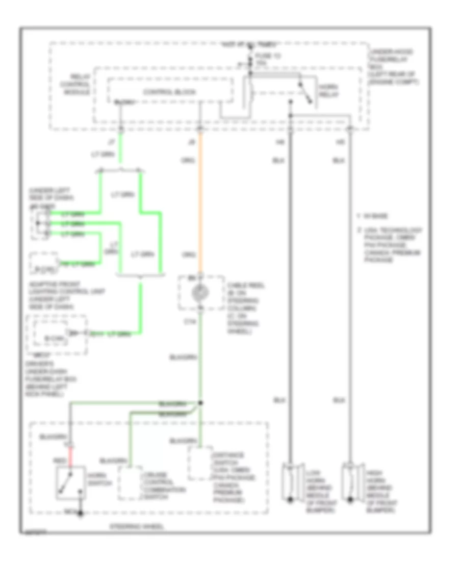
- Cable reel (b: on steering column) (c: on steering wheel)
- Cancel button
- Control block
- Cruise control combination switch
- D10
- D13
- D14
- Decel set button
- Distance button
- Distance switch
- Driver's under-dash fuse/relay box (behind left kick panel)
- E11
- E14
- F12
- Fuse 1 15a
- Fuse 13 15a
- Fuse 18 15a
- Fuse 7 7.5a
- Fuse 8 15a
- Horn relay
- Horns system
- Hot at all times
- Hot in on or start
- Interior lights system
- J/c c510 (behind left side of dash)
- J/c c520 (under steering column cover)
- N26
- N29
- Passenger's under-dash fuse/relay box (behind right kick panel)
- Pgm-fi main relay 1
- Red
- Relay control module
- Res accel button
- Steering wheel
- Throttle actuator control module relay
- Transmissions system
- Under-hood fuse/relay box (left rear of engine compt)
- X10
- X23
Cruise Control Wiring Diagram (1 of 2) for Acura RL 2010
List of elements for Cruise Control Wiring Diagram (1 of 2) for Acura RL 2010:
- (behind left side of dash) j/c c518
- (under
- A14
- A15
- A25
- A26
- App sensor (under left side of dash)
- Apsa
- Apsb
- Atp-fwd
- B15
- B16
- B19
- B22
- Bksw
- Bkswnc
- C11
- C19
- Canh
- Canl
- Computer data lines system
- Cruise control main switch indicator
- Dimming circuit cruise control
- Drive circuit
- Driver's under-dash fuse/relay box (behind left kick panel)
- E12
- E15
- E16
- E26
- Etcs rly
- Ftp sensor (above rear differential)
- Fuse 21 10a
- Fuse 7 10a
- G101 (top front of engine)
- G501
- Gauge control module
- Gnd
- Hot at all times
- Hot in on or start
- J/c c106 (top of transmission)
- J/c c509 (behind left side of dash)
- J/c c510 (behind left side of dash)
- J/c c512 (behind left side of dash)
- J/c c517 (behind middle of dash)
- Left side of dash)
- Mrly
- N13
- Network controller
- Network transceiver fast controller area
- Pcm (under middle of dash)
- Pnk
- Red
- Regulator 10v
- Sedf
- Sefd
- Sg3
- Sg4
- Thl1
- Thl2
- Throttle actuator control module (behind right kick panel)
- Tp sensor/throttle actuator (on throttle body)
- Vcc
- Vcc3
- Vcc4
- Warning
- X34
- X35
Cruise Control Wiring Diagram (2 of 2) for Acura RL 2010
List of elements for Cruise Control Wiring Diagram (2 of 2) for Acura RL 2010:
- (3)
- (under left side of dash) g501
- (under steering column cover) j/c c520
- B15
- Brake pedal position switch (near brake pedal)
- C11
- C12
- C13
- C14
- Cable reel (b: on steering column) (c: on steering wheel)
- Cancel button
- Control block
- Cruise button
- Cruise control combination switch
- D10
- D13
- D14
- Decel set button
- Driver's under-dash fuse/relay box (behind left kick panel)
- E11
- E14
- Exterior lights system
- Fuse 1 15a
- Fuse 13 15a
- Fuse 18 15a
- Fuse 7 7.5a
- Fuse 8 15a
- G101 (top front of engine)
- Horn relay
- Horns system
- Hot at all times
- Hot in on or start
- Interior lights system
- J/c c106 (top of transmission)
- J/c c510 (behind left side of dash)
- N29
- Output shaft (countershaft) speed sensor (in transmission housing)
- Passenger's under-dash fuse/relay box (behind right kick panel)
- Pgm-fi main relay 1
- Relay control module
- Res accel button
- Steering wheel
- Throttle actuator control module relay
- Transmission range switch (on transaxle)
- Transmissions system
- Under-hood fuse/relay box (left rear of engine compt)
- X10
- X23
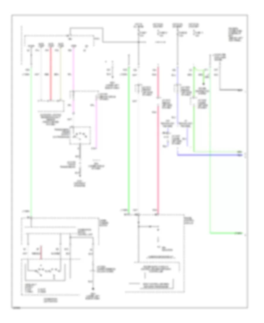
DEFOGGERS
Defoggers Wiring Diagram for Acura RL 2010
List of elements for Defoggers Wiring Diagram for Acura RL 2010:
- (not used)
- A14
- A20
- A28
- B-can
- Base
- Climate control panel
- Climate control unit
- Computer data lines system
- Control block
- D11
- D13
- Defogger
- Di2
- Do2
- Driver's mpcs unit (in driver's door)
- Driver's under-dash fuse/relay box (behind left kick panel)
- E13
- E16
- Except base
- Exterior lights system
- Front passenger's mpcs unit (in front passenger's door)
- Fuse 14 40a
- Fuse 2 30a
- Fuse 30 7.5a
- Fuse 7 10a
- G14
- G503 (under middle of dash)
- G506 (behind glove box)
- G601 (at left side of floor)
- G604 (in left "c" pillar)
- G851 (in right "c" pillar)
- Ground
- Heat
- Hot at all times
- Hot in on
- Ig2
- J/c c305 (under left side of dash)
- J/c c512 (behind left side of dash)
- J/c c515 (behind middle of dash)
- J/c c517 (behind middle of dash)
- J/c c608 (behind left kick panel)
- J/c c755 (in driver's door)
- J/c c757 (in driver's door)
- J/c c775 (in front passenger's door)
- Left power mirror (in driver's door)
- Micu
- N20
- Noise reduction condenser (in right "c" pillar)
- P-ig
- Passenger's under-dash fuse/relay box (behind right kick panel)
- Power window master switch
- Rear window defogger
- Rear window defogger relay
- Rear window defogger/ power mirror heater switch
- Relay control module
- Right power mirror
- Right rear power window switch
- Rr def
- Uart
- Under-hood fuse/relay box (left rear of engine compt)
- Vbu
- X15
- X35
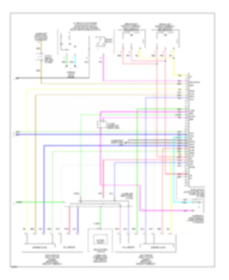
ELECTRONIC POWER STEERING
Electronic Power Steering Wiring Diagram for Acura RL 2010
List of elements for Electronic Power Steering Wiring Diagram for Acura RL 2010:
- B21
- Base
- Canada
- Com
- Controller
- Drive circuit
- Driver's under-dash fuse/relay box (behind left kick panel)
- E11
- E23
- Ecps control unit (under left side of dash)
- Ecps indicator
- Ecps valve (left side of engine compt)
- Except base
- Fuse 21 10a
- Fuse 7 10a
- G401 (under right side of dash)
- G501 (under left side of dash)
- Gauge control module
- Ground
- Hot at all times
- Hot in on or start
- Ig1
- J/c c306 (under left side of dash)
- J/c c510 (behind left side of dash)
- J/c c512 (behind left side of dash)
- Nep
- Pcm (under middle of dash)
- Pnk
- Red
- Usa
- Vsp
- Vssout
- W/l
- X34
- X35
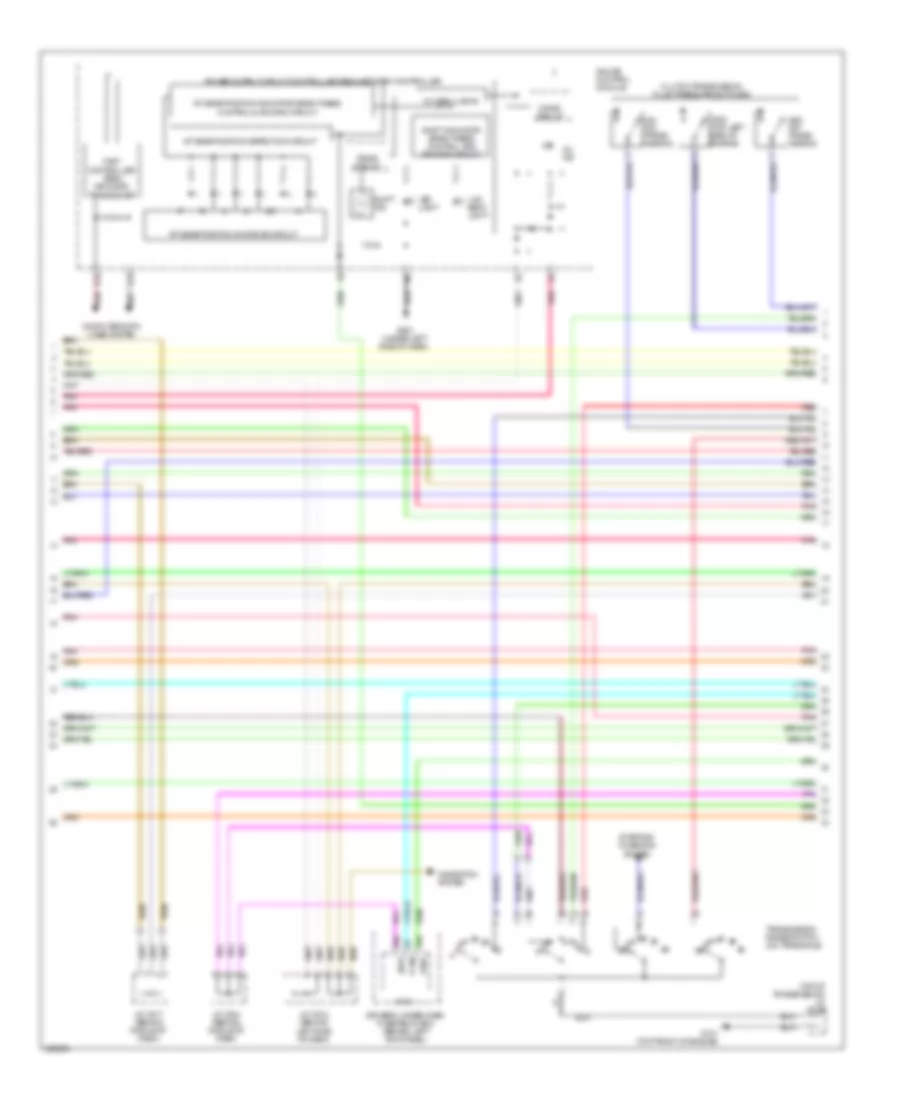
ENGINE PERFORMANCE
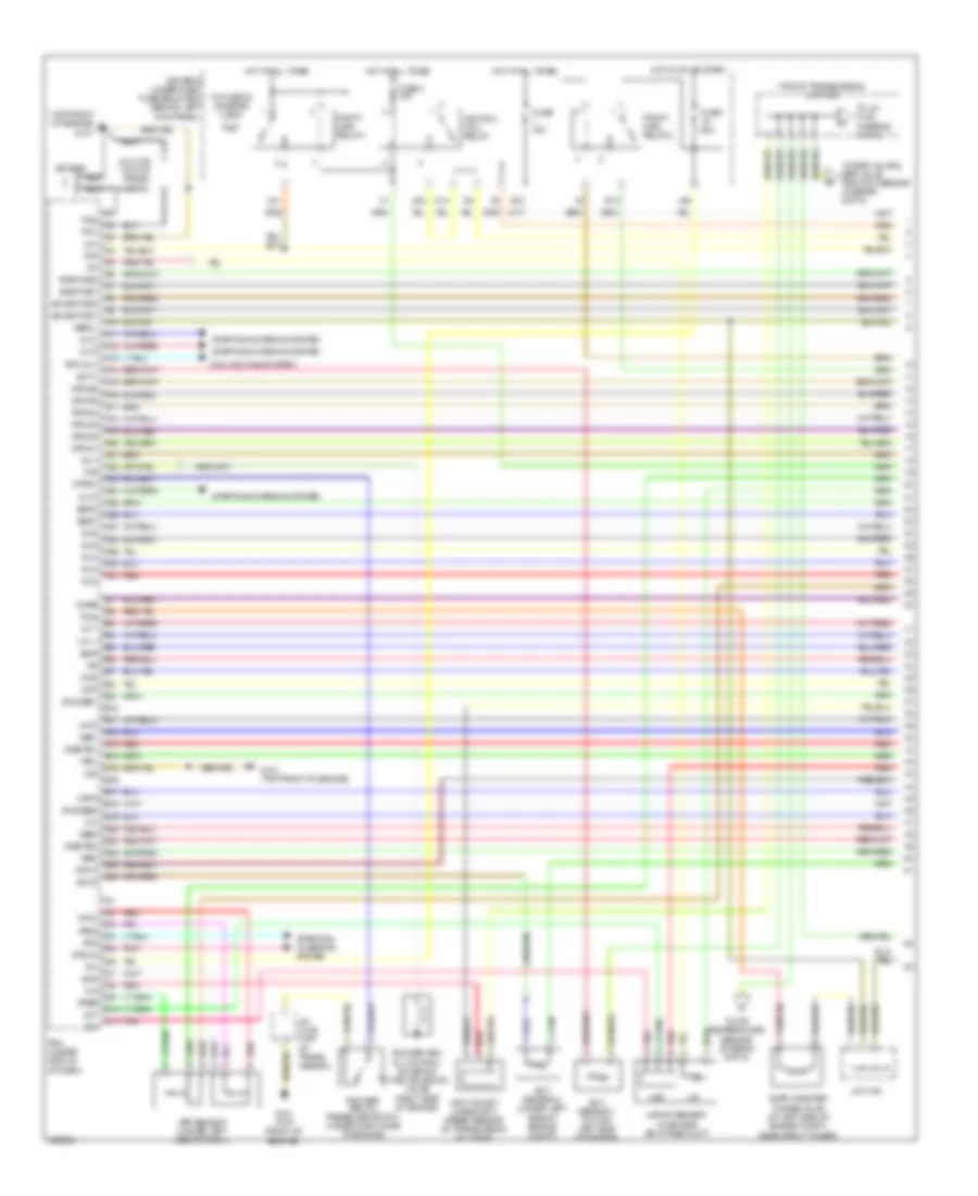
3.7L
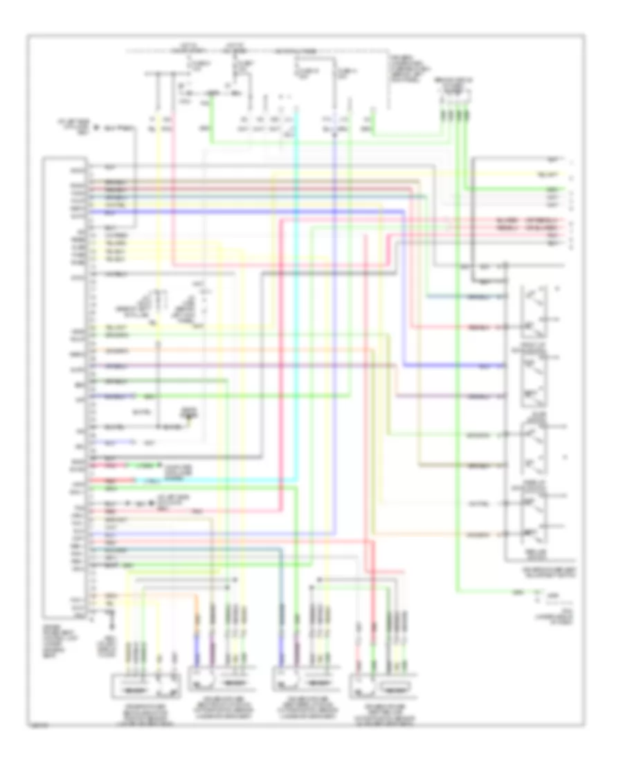
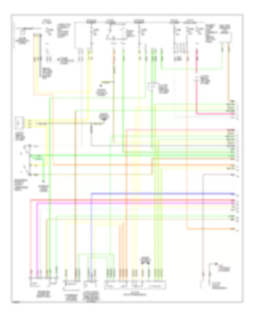
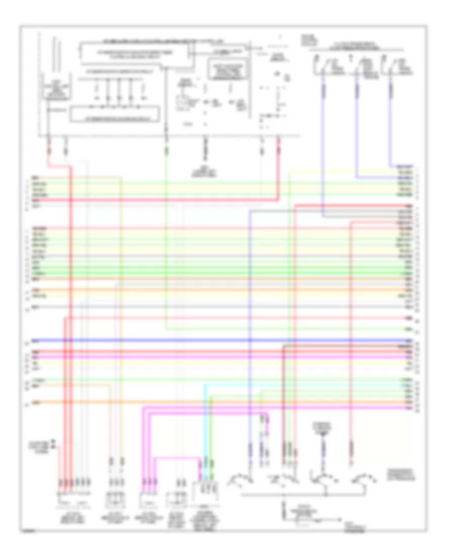
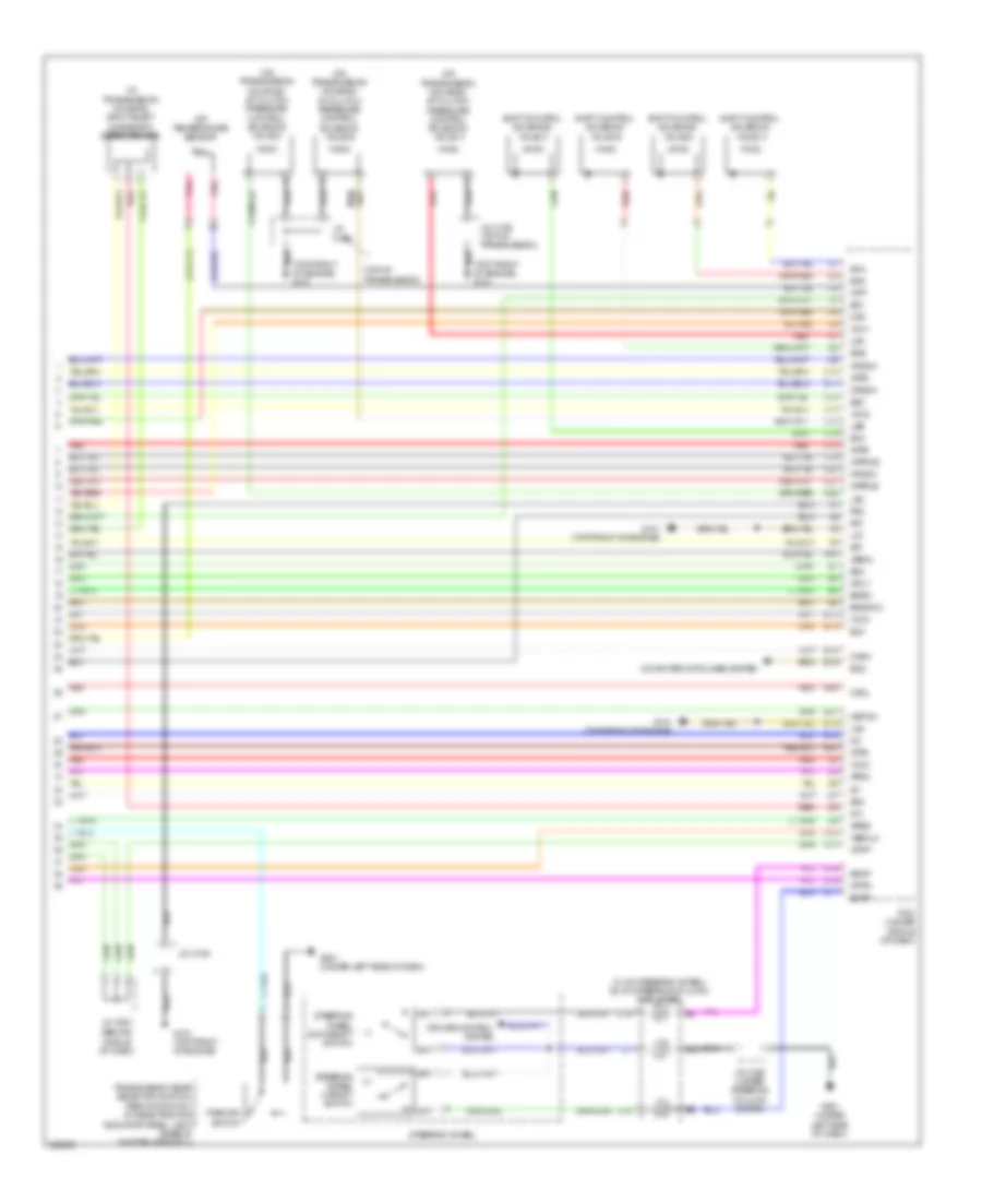
3.7L, Engine Performance Wiring Diagram (1 of 6) for Acura RL 2010
List of elements for 3.7L, Engine Performance Wiring Diagram (1 of 6) for Acura RL 2010:
- (top front of engine) g101
- (top of transmission) j/c c108
- A10
- A11
- A12
- A13
- A14
- A15
- A16
- A17
- A18
- A19
- A20
- A21
- A22
- A23
- A24
- A25
- A26
- A27
- A28
- A29
- A30
- A31
- Afshtcb1
- Afshtcb2
- Altc
- Altf
- Altl
- App sensor (under left side of dash)
- Apsa
- Apsb
- Atp-n
- B10
- B11
- B12
- B13
- B14
- B15
- B16
- B17
- B18
- B19
- B20
- B21
- B22
- B23
- B24
- Ckpa
- Ckpb
- Cmp
- Cooling fans system
- D10
- D11
- Driver's under-dash fuse/relay box (behind left kick panel)
- E13
- Ect sensor 1 (on top left side of engine)
- Ect sensor 2 (under left side of engine compt)
- Ect1
- Ect2
- Egr
- Evap canister purge valve (at left side of engine compt, near strut tower)
- Fuse 15a
- Fuse 2 15a
- Fuse 20a
- G101 (top front of engine)
- Hot at all times
- Hot in on or start
- Iat
- Ig1
- Ignition coil relay
- Igp
- Igpls1
- Igpls2
- Igpls3
- Igpls4
- Igpls5
- Igpls6
- Imt +
- Imt -
- Imtm
- Inj1
- Inj2
- Inj3
- Inj4
- Inj5
- Inj6
- Input shaft (mainshaft) speed sensor (in transmission housing)
- Ipb1
- Ipb2
- J/c c105
- J/c c106 (top of trans- mission)
- Lg1
- Lg2
- Maf
- Maf/iat sensor (in engine air intake duct)
- Mcs
- N14
- Pcm (under middle of dash)
- Pcs
- Pg1
- Pg2
- Pgm-fi main relay 1
- Pgm-fi main relay 2
- Pnk
- Red
- Rfc rly
- Rocker arm oil control solenoid (vtec solenoid valve) (right side of engine)
- Rocker arm oil pressure switch (under right side of engine)
- Sedf
- Sefd
- Sg3
- Sho2sb1
- Sho2sb2
- So2shtcb1
- So2shtcb2
- Starting/ charging system
- Starting/charging system
- Strld
- Sts
- To atf temperature sensor (diagram 6 of 6)
- To egr valve & egr valve position sensor (diagram 6 of 6)
- To fuse 23 (diagram 3 0f 6)
- To j/c c108 (diagram 4 of 6)
- Vbsol
- Vcc3
- Vcentb1
- Vcentb2
- Vg+
- Vg-
- Vsb1
- Vsb2
- Vtpsw
- Vts
- X23
- X31
- X32
- X38
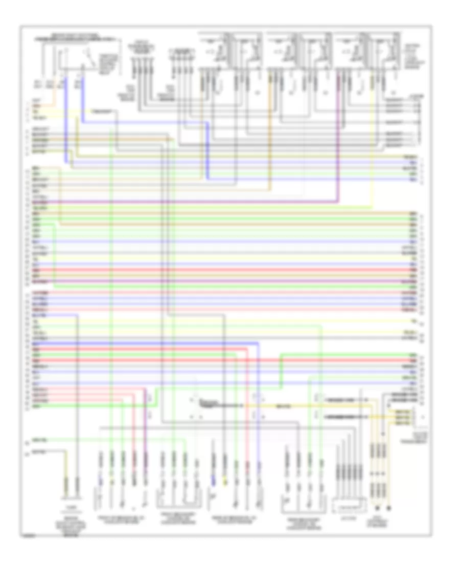
3.7L, Engine Performance Wiring Diagram (2 of 6) for Acura RL 2010
List of elements for 3.7L, Engine Performance Wiring Diagram (2 of 6) for Acura RL 2010:
- (behind right kick panel) passenger's under-dash fuse/relay box
- (top of transmission) j/c c106
- Braided wire
- D14
- E11
- E14
- Engine mount control solenoid valve (middle of engine)
- Front a/f sensor (b2, s1) (middle of engine)
- Front secondary ho2s (b2, s2) (middle of engine)
- G101 (top front of engine)
- Icm
- Ignition coils 1, 2, 3, 4, 5 & 6 (middle of engine)
- J/c c105
- J/c c106 (top of transmission)
- Rear a/f sensor (b1, s1) (middle of engine)
- Rear secondary ho2s (b1, s2) (middle of engine)
- Red
- Throttle actuator control module relay
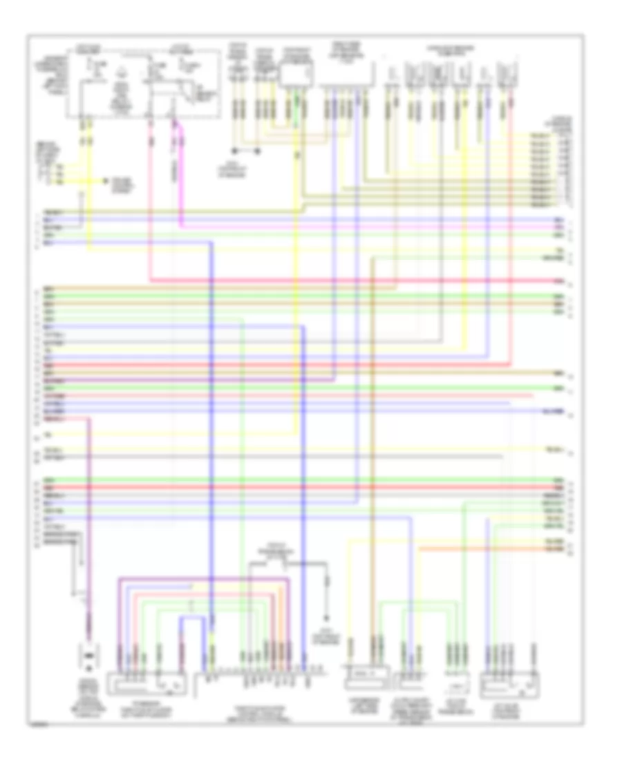
3.7L, Engine Performance Wiring Diagram (3 of 6) for Acura RL 2010
List of elements for 3.7L, Engine Performance Wiring Diagram (3 of 6) for Acura RL 2010:
- (behind left side of dash) j/c c510
- (middle of engine) injectors
- (middle of engine) j/c c107
- (right side of engine) ckp sensors (1 & 2)
- (top front of engine) cmp sensor
- (top of trans- mission) j/c c106
- (top of trans- mission) j/c c108
- (top of transmission) j/c c106
- A/f sensor relay
- Braided wire
- Cruise control system
- Driver's under-dash fuse/relay box (behind left kick panel)
- From pgm-fi main relay 1 (diagram 1 of 6)
- Fuse 15a
- Fuse 4 15a
- Fuse 7.5a
- G101 (top front of engine)
- Gnd
- Hot at all times
- Hot in on or start
- Imt valve (top front of engine)
- J/c c108 (top of transmission)
- Knock sensor (on top middle of engine, below intake manifold)
- Map sensor (left side of engine)
- N29
- Output shaft (countershaft) speed sensor (in transmission housing)
- Pnk
- Red
- Sedf
- Sefd
- Thl1
- Thl2
- Throttle actuator control module (behind right kick panel)
- Tp sensor/ throttle actuator (on throttle body)
- Vcc
- X36
3.7L, Engine Performance Wiring Diagram (4 of 6) for Acura RL 2010
List of elements for 3.7L, Engine Performance Wiring Diagram (4 of 6) for Acura RL 2010:
- (above rear differential) ftp sensor
- (behind right kick panel) passenger's under-dash fuse/relay box
- (in left "c" pillar) fuel pump control module
- (left rear of engine compt) under-hood fuse/relay box
- (under left side of rear seat) fuel tank unit
- (under rear of vehicle) evap canister vent shut valve
- Audio
- C11
- Driver's under- dash fuse/relay box (behind left kick panel)
- E16
- Ecps control unit (under left side of dash)
- Eld unit
- Fp+
- Fp-
- Fpc
- From j/c c108 d (diagram 1 of 6)
- Fuel pump
- Fuse 10a
- Fuse 15a
- G301 (behind left side of front bumper)
- G401 (under right side of dash)
- G603 (in left "c" pillar)
- Headlights system
- Hot at all times
- Hot in on or start
- J/c c108 (top of transmission)
- J/c c306 (base) (under left side of dash)
- J/c c509 (behind left side of dash)
- J/c c510 (behind left side of dash)
- J/c c512 (behind left side of dash)
- N13
- Pnk
- Power distribution system
- Psp switch (right side of engine)
- Red
- System
- X17
- X34
- X35
3.7L, Engine Performance Wiring Diagram (5 of 6) for Acura RL 2010
List of elements for 3.7L, Engine Performance Wiring Diagram (5 of 6) for Acura RL 2010:
- (top of transmission) j/c c106
- 10v regulator
- 2nd (top left side of engine)
- 3rd (on trans- mission)
- 4th (on trans- mission)
- A/t gear position detection circuit
- A/t gear position ind drive circuit
- A/t gear position indicator brightness control & dimming circuit
- Atpp
- Atpr
- B15
- B16
- Clutch transmission fluid pressure switches
- Computer data lines system
- Drive circuit
- Driver's under-dash fuse/relay box (behind left kick panel)
- Fast controller area network transceiver
- G101 (top front of engine)
- G501 (under left side of dash)
- Gauge control module
- J/c c512 (behind left side of dash)
- J/c c517 (behind middle of dash)
- J/c c521 (behind middle of dash)
- Lcd back light
- Led light
- Micu
- Mil ind
- Navigation system
- P-pin
- P16
- P20
- Pnk
- Red
- Shift ind
- Shift indicator brightness control and dimming circuit
- Starting/ charging system
- Transmission range switch (on transaxle)
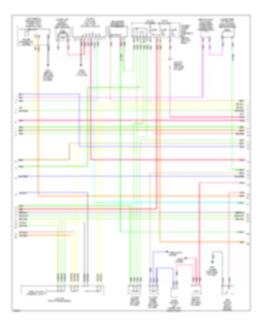
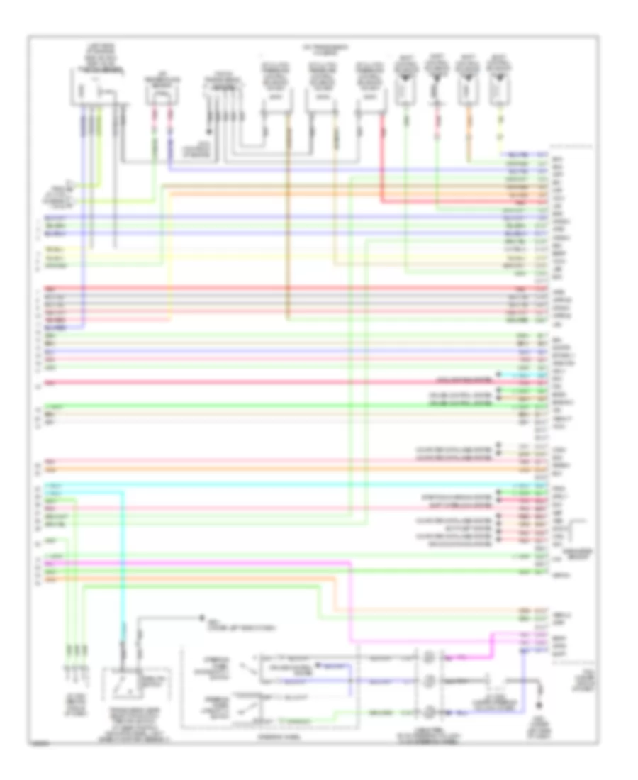
3.7L, Engine Performance Wiring Diagram (6 of 6) for Acura RL 2010
List of elements for 3.7L, Engine Performance Wiring Diagram (6 of 6) for Acura RL 2010:
- (left side of engine) egr valve & egr valve position sensor
- (on transmission housing)
- (top of transmission) j/c c106
- A/t clutch pressure control solenoid valve a
- A/t clutch pressure control solenoid valve b
- A/t clutch pressure control solenoid valve c
- Acc
- Afshtcr
- Air conditioning system
- Anti-theft system
- Atf temperature sensor
- Atft
- Atp-r
- Atpd
- Atpfwd
- Atpp
- Atprvs
- Atps
- B15
- Barometer sensor
- Bksw
- Bkswnc
- C10
- C11
- C12
- C13
- C14
- C15
- C16
- C17
- C18
- C19
- C20
- C21
- C22
- Cable reel (b: on steering column) (c: on steering wheel)
- Canh
- Canl
- Computer data lines system
- Cooling fans system
- Cruise control system
- D12
- D13
- D14
- D15
- D16
- D17
- E10
- E11
- E12
- E13
- E14
- E15
- E16
- E17
- E18
- E19
- E20
- E21
- E22
- E23
- E24
- E25
- E26
- E27
- E28
- E29
- E30
- E31
- Egrp
- Eld
- Etcsrly
- Fpc
- Fpcd
- From b j/c c108 (diagram c 1 of 6)
- Ftp
- G101 (top front of engine)
- G501 (under left side of dash)
- Imocd
- Imofpr
- J/c c520 (under steering column cover)
- J/c c521 (behind middle of dash)
- Lsa
- Lsb
- Lsc
- Map
- Metinh
- Mrly
- Nep
- Op2sw
- Op3sw
- Op4sw
- Park pin switch
- Pcm (under middle of dash)
- Pnk
- Pspsw
- Red
- Rfc
- Scs
- Sdnp
- Sg1
- Sg2
- Sg4
- Sha
- Shb
- Shc
- Shd
- Shift control solenoid valve a
- Shift control solenoid valve b
- Shift control solenoid valve c
- Shift control solenoid valve d
- Shift interlock system
- Sls
- Starting/charging system
- Steering wheel
- Steering wheel downshift (-) switch
- Steering wheel upshift (+) switch
- Strly
- Supp
- Transmission gear selection switch/ park pin switch/ a/t gear position indicator panel light (base of shifter assembly)
- Vbsol2
- Vcc1
- Vcc2
- Vcc4
- Vssout
- Vsv
- Wen
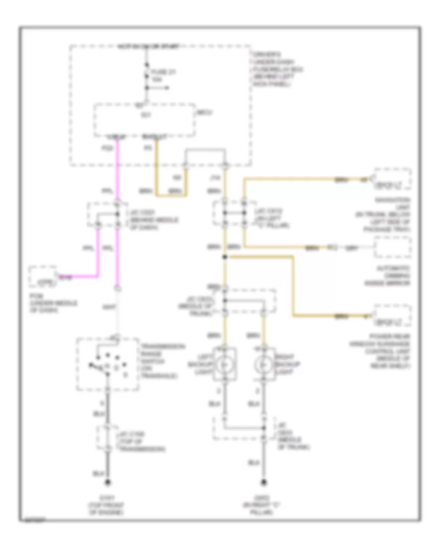
EXTERIOR LIGHTS
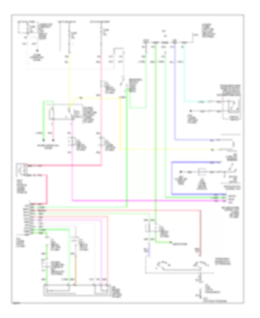
Backup Lamps Wiring Diagram for Acura RL 2010
List of elements for Backup Lamps Wiring Diagram for Acura RL 2010:
- Atp-r
- Atpr
- Automatic dimming inside mirror
- Back lt
- D16
- Driver's under-dash fuse/relay box (behind left kick panel)
- Fuse 21 10a
- G101 (top front of engine)
- G652 (in right "c" pillar)
- Hot in on or start
- Ig1
- J/c c106 (top of transmission)
- J/c c521 (behind middle of dash)
- J/c c612 (in left "c" pillar)
- J/c c833 (middle of trunk)
- J14
- Left backup light
- Micu
- N r
- Navigation unit (in trunk, below left side of package tray)
- P20
- Pcm (under middle of dash)
- Power rear window sunshade control unit (middle of rear shelf)
- Right backup light
- Transmission range switch (on transaxle)
Exterior Lamps Wiring Diagram, with CMBS/PAX; Elite Package (1 of 3) for Acura RL 2010
List of elements for Exterior Lamps Wiring Diagram, with CMBS/PAX; Elite Package (1 of 3) for Acura RL 2010:
- 10a
- 2) auto 3) head
- 7.5a
- Adaptive cruise control relay
- Adaptive cruise control unit (behind right side of dash)
- Adaptive front lighting control unit (under left side of dash)
- Auto lt sig
- Auto lt sio
- Auto lt sip
- Automatic lighting sensor/sunlight sensor (front center of dash)
- Auxiliary under-hood relay box (left side of engine compt)
- B-can
- B10
- B12
- Brake pedal position switch (near brake pedal)
- Combination light switch
- Combination switch control unit
- Driver's under-dash fuse/relay box (behind left kick panel)
- F12
- Fuse 21
- Fuse 29
- Fuse 7
- G501 (under left side of dash)
- G502 (under left side of dash)
- G601 (at left side of floor)
- Headlight switch 0) off 1) park
- High mount brake light
- Hot at all times
- Hot in on or start
- Ig1
- J/c c307 (under left side of dash)
- J/c c508 (behind left side of dash)
- J/c c510 (behind left side of dash)
- J/c c512 (behind left side of dash)
- J/c c519 (under left side of dash)
- J/c c520 (under steering column cover)
- J/c c612 (in left "c" pillar)
- Micu
- Millimeter wave radar (behind front grille)
- N26
- N28
- Navigation unit (in trunk, below left side of package tray)
- P14
- P27
- P30
- Pcm (under middle of dash)
- Pnk
- Red
- Sg-1
- Stop sw
- To driver's under-dash fuse/relay box (diagram 2 0f 3)
- Turn signal light switch
- Vbu
- Wiper/ washer switch
- X10
- X20
- X34
- X35
Exterior Lamps Wiring Diagram, with CMBS/PAX; Elite Package (2 of 3) for Acura RL 2010
List of elements for Exterior Lamps Wiring Diagram, with CMBS/PAX; Elite Package (2 of 3) for Acura RL 2010:
- (not used)
- B11
- D13
- D17
- Driver's under-dash fuse/relay box (behind left kick panel)
- F10
- From driver's under-dash fuse/relay box (diagram 1 0f 3)
- G301 (behind left side of front bumper)
- G501 (under left side of dash)
- G503 (under middle of dash)
- G601 (at left side of floor)
- G701 (left side of trunk)
- Gauge control module
- Gnd
- Hazard sw
- Hazard warning switch light
- Hazard warning switch/front passenger's air bag cut-off indicator
- Interior lights system
- J/c c516 (behind middle of dash)
- L turn
- L turn lt
- Left brake light (14)
- Left brake light/ taillight
- Left front turn signal light
- Left rear turn signal light
- Left side marker light
- Left taillight (14)
- Left turn signal indicator
- Micu
- N27
- N31
- N33
- N38
- N44
- N45
- P28
- R turn lt
- Red
- Right brake light (14)
- Right brake light/ taillight
- Right rear turn signal light
- Right side marker light
- Right taillight (14)
- Right turn signal indicator
- Turn +b hzd signal/ hazard r turn relay 1
- Turn signal/ hazard relay 2 (sounder) (under left side of dash)
- Turn sw
- Turn sw l
- Turn sw r
Exterior Lamps Wiring Diagram, with CMBS/PAX; Elite Package (3 of 3) for Acura RL 2010
List of elements for Exterior Lamps Wiring Diagram, with CMBS/PAX; Elite Package (3 of 3) for Acura RL 2010:
- (behind glove box)
- (not used)
- 15a
- Control block
- Fuse 13
- Fuse 16
- Fuse 4
- G201
- G301 (behind left side of front bumper)
- G506
- G601 (at left side of floor)
- G652 (in right "c" pillar)
- H13
- H14
- Headlights system
- Hot at all times
- Interior lights system
- J/c c507 (behind left side of dash)
- J/c c833 (middle of
- Left front parking light
- Left license plate light
- Left power mirror
- Left side turn signal light
- Passenger's under-dash fuse/relay box (behind right kick panel)
- Pnk
- Relay control module
- Right front parking light
- Right front turn signal light
- Right license plate light
- Right power mirror
- Right side turn signal light
- Taillight relay
- Trunk)
- Under-hood fuse/relay box (left rear of engine compt)
Exterior Lamps Wiring Diagram, without CMBS/PAX; Elite Package (1 of 3) for Acura RL 2010
List of elements for Exterior Lamps Wiring Diagram, without CMBS/PAX; Elite Package (1 of 3) for Acura RL 2010:
- 0) off 1) park
- 10a
- 2) auto 3) head
- Auto lt sig
- Auto lt sio
- Auto lt sip
- Automatic lighting sensor/sunlight sensor (front center of dash)
- B-can
- B10
- B12
- Brake pedal position switch (near brake pedal)
- Combination light switch
- Combination switch control unit
- Driver's under-dash fuse/relay box (behind left kick panel)
- F12
- Fuse 21
- Fuse 7
- G501 (under left side of dash)
- G502 (under left side of dash)
- G601 (at left side of floor)
- Headlight switch
- High mount brake light
- Hot at all times
- Hot in on or start
- Ig1
- J/c c510 (behind left side of dash)
- J/c c512 (behind left side of dash)
- J/c c519 (under left side of dash)
- J/c c520 (under steering column cover)
- J/c c607 (behind left kick panel)
- J/c c612 (in left "c" pillar)
- Micu
- N26
- N28
- Navigation unit (in trunk, below left side of package tray)
- P14
- P27
- P30
- Pcm (under middle of dash)
- Pnk
- Red
- Sg-1
- Stop sw
- To driver's under-dash fuse/relay box (diagram 2 0f 3)
- Turn signal light switch
- Vbu
- Wiper/ washer switch
- X10
- X34
- X35
Exterior Lamps Wiring Diagram, without CMBS/PAX; Elite Package (2 of 3) for Acura RL 2010
List of elements for Exterior Lamps Wiring Diagram, without CMBS/PAX; Elite Package (2 of 3) for Acura RL 2010:
- (not used)
- +b haz
- B11
- D13
- D17
- Driver's under-dash fuse/relay box (behind left kick panel)
- F10
- From driver's under-dash fuse/relay box (diagram 1 0f 3)
- G301 (behind left side of front bumper)
- G501 (under left side of dash)
- G503 (under middle of dash)
- G601 (at left side of floor)
- G701 (left side of trunk)
- Gauge control module
- Gnd
- Hazard sw
- Hazard warning switch light
- Hazard warning switch/front passenger's air bag cut-off indicator
- Interior lights system
- J/c c516 (behind middle of dash)
- L turn
- Left brake light (14)
- Left brake light/ taillight
- Left front turn signal light
- Left rear turn signal light
- Left side marker light
- Left taillight (14)
- Left turn signal indicator
- Micu
- N27
- N31
- N33
- N38
- N44
- N45
- P28
- R turn
- Red
- Right brake light (14)
- Right brake light/ taillight
- Right rear turn signal light
- Right side marker light
- Right taillight (14)
- Right turn signal indicator
- Turn signal/ hazard relay 1
- Turn signal/ hazard relay 2 (sounder) (under left side of dash)
- Turn sw l
- Turn sw r
Exterior Lamps Wiring Diagram, without CMBS/PAX; Elite Package (3 of 3) for Acura RL 2010
List of elements for Exterior Lamps Wiring Diagram, without CMBS/PAX; Elite Package (3 of 3) for Acura RL 2010:
- (behind glove box)
- (not used)
- 15a
- Control block
- Fuse 13
- Fuse 16
- Fuse 4
- G201
- G301 (behind left side of front bumper)
- G506
- G601 (at left side of floor)
- G652 (in right "c" pillar)
- H13
- H14
- Headlights system
- Hot at all times
- Interior lights system
- J/c c507 (behind left side of dash)
- J/c c833 (middle of
- Left front parking light
- Left license plate light
- Left power mirror
- Left side turn signal light
- Passenger's under-dash fuse/relay box (behind right kick panel)
- Pnk
- Relay control module
- Right front parking light
- Right front turn signal light
- Right license plate light
- Right power mirror
- Right side turn signal light
- Taillight relay
- Trunk)
- Under-hood fuse/relay box (left rear of engine compt)
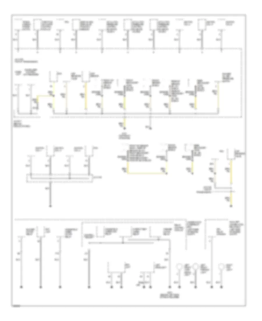
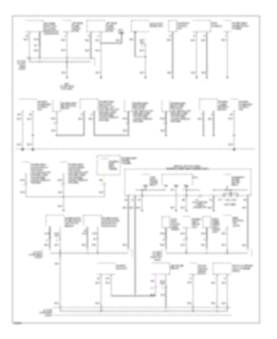
GROUND DISTRIBUTION
Ground Distribution Wiring Diagram (1 of 5) for Acura RL 2010
List of elements for Ground Distribution Wiring Diagram (1 of 5) for Acura RL 2010:
- A10
- A22
- A23
- B10
- B11
- B14
- Battery
- Blower power transistor
- Braided wire
- Coin pocket light
- Driver's under-dash fuse/relay box (behind left kick panel)
- E-pretensioner unit (usa: cmbs/ pax package) (canada: premium package)
- Front passenger's door lock actuator/ knob switch/ door switch
- Front passenger's door outer handle light/ touch sensor
- Front passenger's mpcs unit
- Front seat heater relay
- Fuel fill door opener relay
- Fuel pump control module
- G1 (left side of engine compt)
- G2 (right side of engine compt)
- G502 (under left side of dash)
- G505 (under center console)
- G506 (behind glove box)
- G603 (in left "c" pillar)
- G604 (in left "c" pillar)
- G653 (behind right kick panel)
- G701 (left side of trunk)
- G801 (in rear of roof)
- G851 (in right "c" pillar)
- Glove box light
- Headlight washer relay (canada)
- Interface dial
- J/c c775 (in front passenger's door)
- J/c c776 (in front passenger's door)
- Keyless answer back buzzer
- Left brake light/ taillight
- Mes connector
- Micu
- Noise reduction condenser
- Passenger's under-dash fuse/relay box (behind right kick panel)
- Rear window defogger
- Right brake light/ taillight
- Right power mirror
- Right side engine mount
- Srs unit
- Steering angle sensor
- Transmission
- Trunk lid latch switch/ opener solenoid
- Trunk lid opener main switch
- Xm antenna/ xm receiver shield (usa: base, canada) xm antenna/ acura link control unit shield (xm receiver) (usa: technology package, cmbs/pax package)
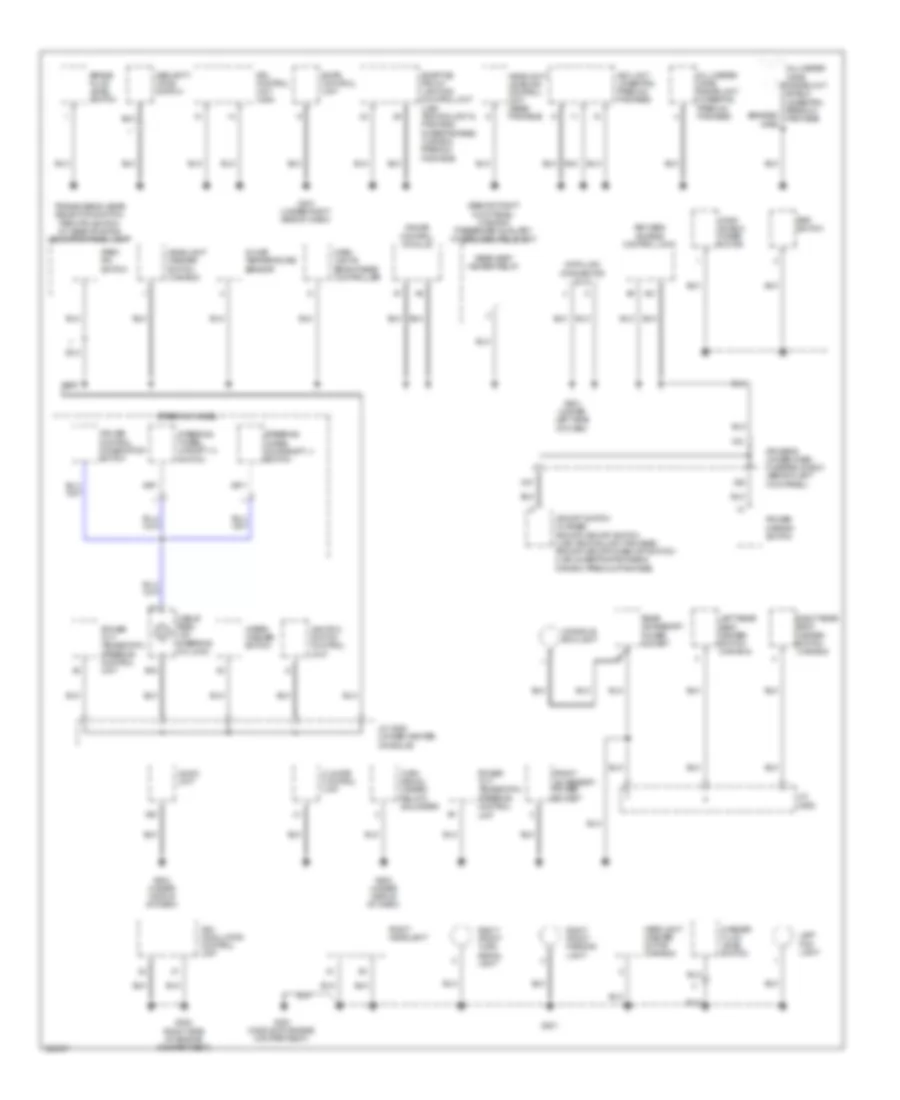
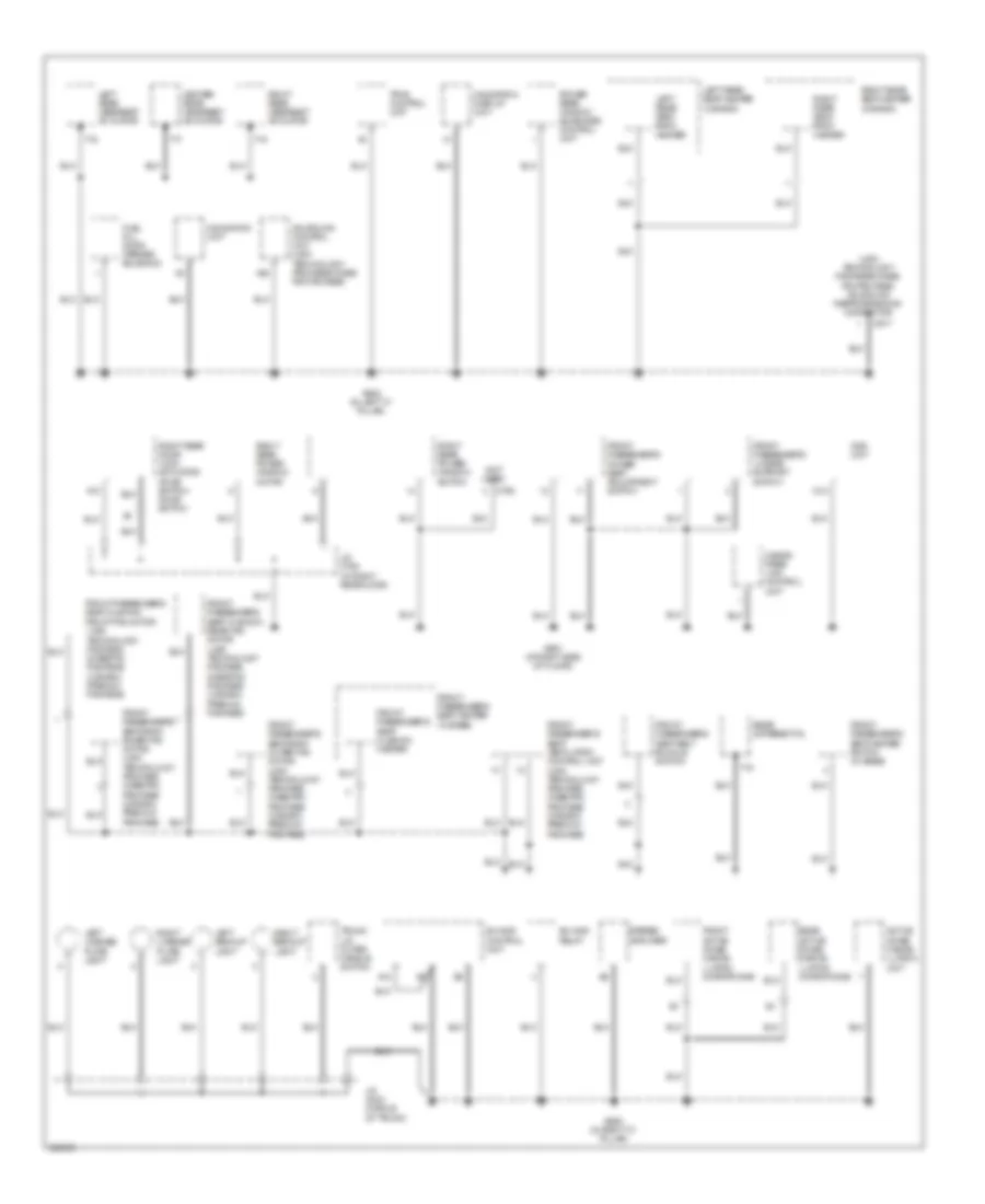
Ground Distribution Wiring Diagram (2 of 5) for Acura RL 2010
List of elements for Ground Distribution Wiring Diagram (2 of 5) for Acura RL 2010:
- A/t clutch pressure control solenoid valve a
- A/t clutch pressure control solenoid valve b
- A/t clutch pressure control solenoid valve c
- Auxiliary under-hood relay box (left side of engine compt)
- B15
- Blower motor relay
- Braided wire
- Ckp sensors (a & b)
- Cmp sensor
- Control block
- Drl relay (canada)
- Egr valve & egr valve position sensor
- Eld unit
- F19
- Front a/f sensor (b2, s1) shield
- Front a/f sensor (b2,s1), rear a/f sensor (b1,s1), front secondary ho2s (b2,s2) & rear secondary ho2s (b1,s2) shields
- Front secondary ho2s (b2, s2) shield
- G101 (top front of engine)
- G301 (behind left side of front bumper)
- Ignition coil 1
- Ignition coil 2
- Ignition coil 3
- Ignition coil 4
- Ignition coil 5
- Ignition coil 6
- Immobilizer control unit-receiver
- Imoes unit
- Intermittent wiper relay
- J/c c105
- J/c c106 (top of transmission)
- J/c c108 (top of transmission)
- J/c c517 (behind middle of dash)
- J10
- Knock sensor shield
- Left front parking light
- Left front turn signal light
- Left headlight
- Pcm
- Rear a/f sensor (b1, s1) shield rear a/f secondary ho2s (b1, s2) shield
- Rear secondary ho2s (b1, s2) shield
- Rear secondary ho2s (b2, s2) shield
- Relay control module
- Rfc unit
- Right fog light
- Rocker oil arm pressure switch
- Throttle actuator control module
- Trans- mission range switch
- Under-hood fuse/relay box (left rear of engine compt)
- Usa
- Washer motor relay
- Windshield wiper high relay
- Windshield wiper motor relay
Ground Distribution Wiring Diagram (3 of 5) for Acura RL 2010
List of elements for Ground Distribution Wiring Diagram (3 of 5) for Acura RL 2010:
- (behind right kick panel) (canada) passenger auxiliary under-dash relay box
- A20
- A21
- Acc unit (cmbs/pax; premium package)
- Adaptive front lighting control unit (usa: technology & package, cmbs/package) (canada: premium package)
- Audio unit
- B15
- Braided wire
- Brake fluid level switch
- Cable reel (on steering column)
- Climate control unit
- Console box light
- Cruise control combination switch
- Dash lights brightness controller
- Data link connector (dlc)
- Driver's under-dash fuse/relay box (behind left kick panel)
- Drl control unit (usa)
- Ecps control unit
- Front accessory power socket
- G201
- G202 (right side of engine compartment)
- G351 (middle of engine compartment)
- G401 (under right side of dash)
- G501 (under left side of dash)
- G503 (under middle of dash)
- G504 (under middle of dash)
- Gauge control module
- Headlight leveling control unit (base package)
- Headlight washer motor (canada)
- Headlight washer switch (canada)
- Ignition switch control unit
- In-car temperature sensor
- J/c c520 (under center console)
- J/c c552
- Keyless access control unit
- Left fog light
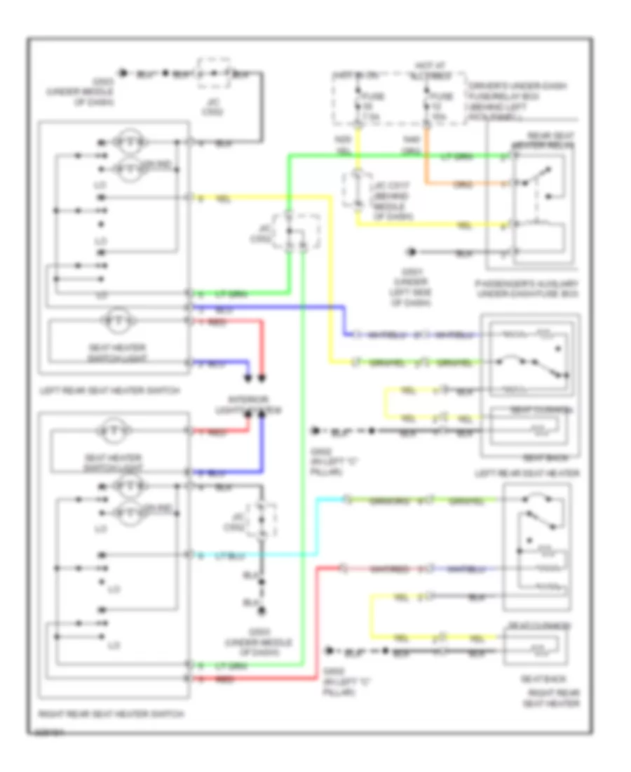
- Left rear seat heater switch (canada)
- Millimeter wave radar unit (cmbs/pax; premium package)
- Millimeter wave radar unit shield (cmbs/pax; premium package)
- N21
- N37
- Park pin switch
- Power mirror switch
- Power tilt/ telescopic steering control unit
- Psp switch
- Rear accessory power socket
- Rear seat heater relay
- Right front parking light
- Right front turn signal light
- Right headlight
- Right rear seat heater switch (canada)
- Security hood switch
- Steering wheel
- Steering wheel downshift (-) switch
- Steering wheel upshift (+) switch
- Transmission gear selection switch/ park pin switch/ a/t gear position indicator panel light
- Turn signal/ hazard relay 2 (sounder)
- Vsa modulator control unit
- Vsa off switch (w/ base) afs off/vsa off switch (usa: technology package) afs off/vsa off/cmbs off switch (usa: cmbs/pax package & canada: premium package)
- Washer fluid level switch
- Wind- shield wiper motor
- Wiper/ washer switch
- X28
Ground Distribution Wiring Diagram (4 of 5) for Acura RL 2010
List of elements for Ground Distribution Wiring Diagram (4 of 5) for Acura RL 2010:
- (behind left kick panel) driver's under-dash fuse/relay box
- (not used)
- Accessory power socket relay
- Auto- matic dimming inside mirror
- B14
- B18
- Driver's door lock actuator/ knob switch/ door switch
- Driver's door outer handle light/touch sensor
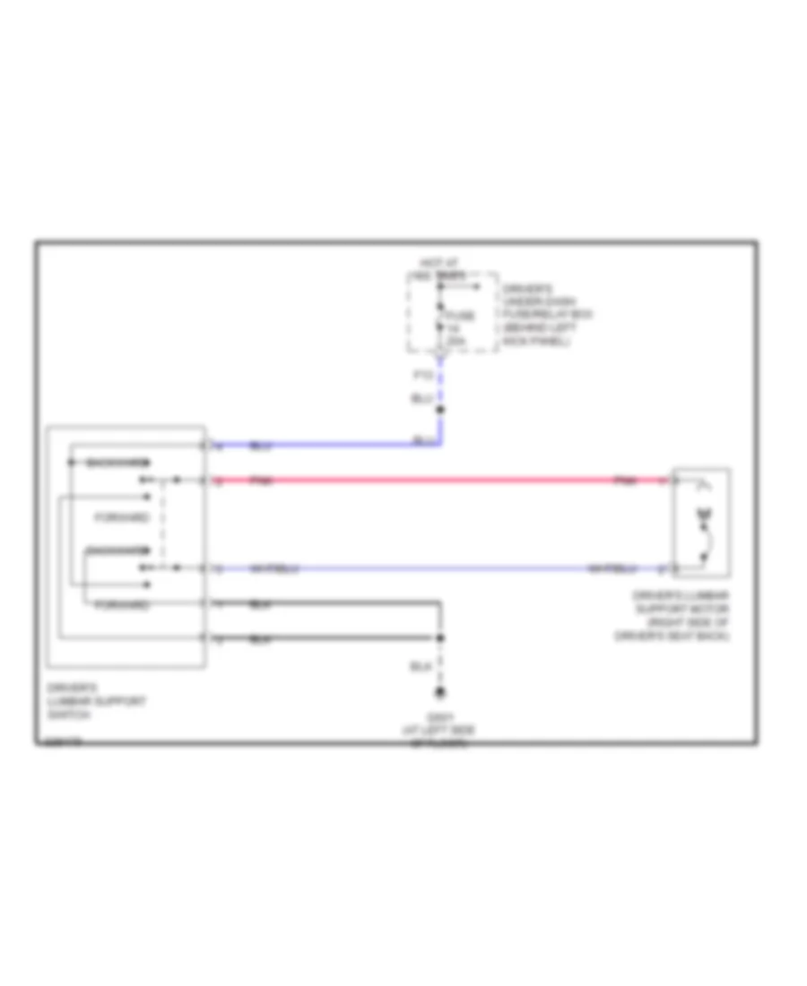
- Driver's lumbar support switch
- Driver's mpcs unit
- Driver's power seat control unit
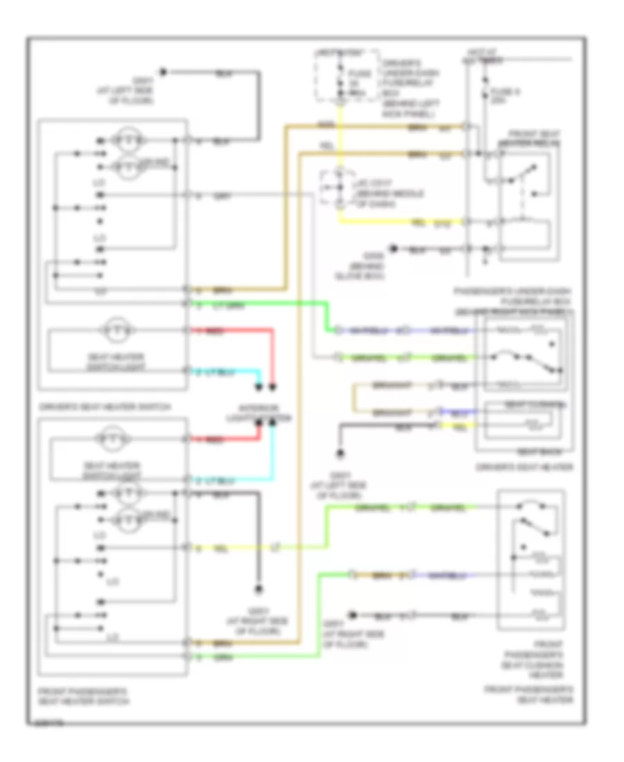
- Driver's seat back heater
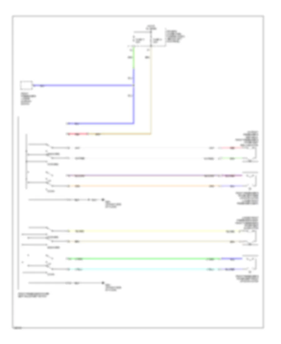
- Driver's seat back inner fan motor (usa: technology package, cmbs/ pax package) (canada: premium package)
- Driver's seat back outer fan motor (usa: technology package, cmbs/ pax package) (canada: premium package)
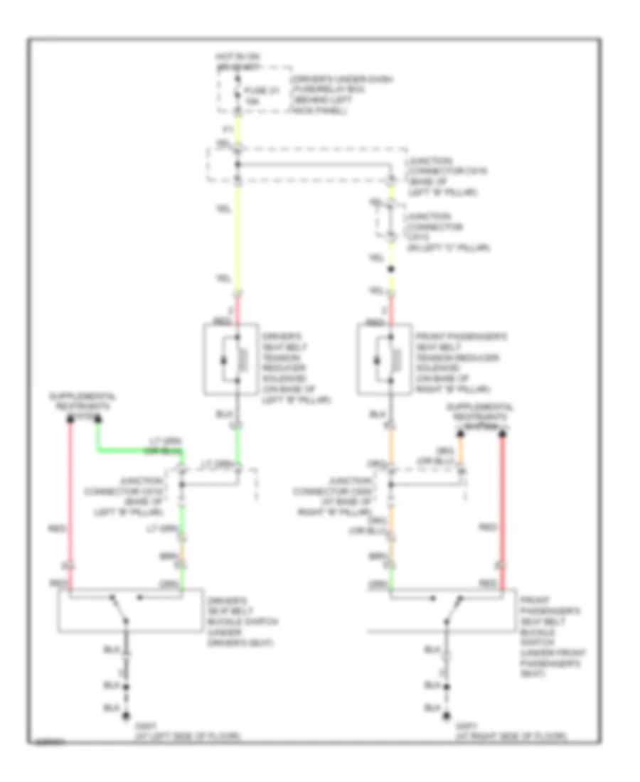
- Driver's seat belt buckle switch
- Driver's seat cushion front fan motor (usa: technology package, cmbs/ pax package) (canada: premium package)
- Driver's seat cushion rear fan motor (usa: technology package, cmbs/ pax package) (canada: premium package)
- Driver's seat heater (w/ base)
- Driver's seat heater switch (w/ base)
- Driver's seat ventilation control unit (usa: technology package, cmbs/ pax package) (canada: premium package)
- Driver's vanity mirror light
- Driving position memory switch
- Front passe- nger's vanity mirror light
- G601 (at left side of floor)
- Gnd
- High mount brake light
- J/c c756 (in driver's door)
- J/c c757 (in driver's door)
- J/c c783 (in left rear door)
- J/c c852 (in left front of roof)
- Left power mirror
- Left rear door lock actuator/ knob switch/ door switch
- Left rear power window motor
- Left rear power window switch
- M1 micu service check connector
- Micu
- Moonroof control unit
- N17
- N18
- N42
- Nca
- Q14
- Rear individual map lights
- Roof console
- Sg-2
- Trunk lid opener/ fuel lid opener switch
- Turn signal/ hazard relay 1
Ground Distribution Wiring Diagram (5 of 5) for Acura RL 2010
List of elements for Ground Distribution Wiring Diagram (5 of 5) for Acura RL 2010:
- (not used)
- (usa: technology packages cmbs/ pax package) acuralink reprogramming connector
- A10
- A12
- A28
- Active noise cance- llation unit
- Acuralink control unit (usa: technology packages cmbs/ pax package)
- C617
- C792
- Center rear headrest actuator
- D12
- Front active noise cance- llation microphone
- Front passenger's lumbar support switch
- Front passenger's power seat adjustment switch
- Front passenger's seat back outer fan motor (usa: technology package, cmbs/pax package) (canada: premium package)
- Front passenger's seat belt buckle switch
- Front passenger's seat cushion front fan motor (usa: technology package, cmbs/pax package) (canada: premium package)
- Front passenger's seat cushion heater
- Front passenger's seat cushion rear fan motor (usa: technology package, cmbs/pax package) (canada: premium package)
- Front passenger's seat heater (w/ base)
- Front passenger's seat heater switch (w/ base)
- Front passenger's seat ventilation control unit (usa: technology package, cmbs/pax package) (canada: premium package)
- Front passengers seat back inner fan motor (usa: technology package, cmbs/pax package) (canada: premium package)
- Fuel fill door opener solenoid
- G602 (in left "c" pillar)
- G651 (at right side of floor)
- G652 (in right "c" pillar)
- Hands- free- link control unit
- J/c c793 (in right rear door)
- J/c c833 (middle of trunk)
- Left backup light
- Left license plate light
- Left rear headrest actuator
- Left rear seat back heater
- Left rear seat heater (canada)
- Navigation display unit
- Navigation unit
- Ods unit
- Power rear window sunshade control unit
- Rear active noise cance- llation microphone
- Rear differential
- Right backup light
- Right license plate light
- Right rear door lock actuator/ knob switch/ door switch
- Right rear headrest actuator
- Right rear power window motor
- Right rear power window switch
- Right rear seat back heater
- Right rear seat heater (canada)
- Sh-awd control unit
- Sh-awd relay
- Stereo amplifier
- T15
- T16
- T17
- T18
- Tpms control unit
- Trunk lid outer handle switch
HEADLIGHTS
Adaptive Front Lighting Wiring Diagram (1 of 2) for Acura RL 2010
List of elements for Adaptive Front Lighting Wiring Diagram (1 of 2) for Acura RL 2010:
- (under left side of dash)
- 10a
- 15a
- 2) auto 3) head
- 7.5a
- Afs indicator
- Atpr
- Auto lt sig
- Auto lt sio
- Auto lt sip
- Automatic lighting sensor/sunlight sensor (front center of dash)
- B-can
- B12
- B17
- Body controller area network transceiver
- Combination light switch
- Combination switch control unit
- Computer data lines system
- D11
- D16
- Driver's under-dash fuse/relay box (behind left kick panel)
- Fuse 11
- Fuse 21
- Fuse 29
- Fuse 7
- G101 (top front of engine)
- G501
- G501 (under left side of dash)
- Gauge control module
- Headlight switch 0) off 1) park
- Hot at all times
- Hot in on or start
- Ig1
- J/c c106 (top of transmission)
- J/c c305 (under left side of dash)
- J/c c307 (under left side of dash)
- J/c c508 (behind left side of dash)
- J/c c510 (behind left side of dash)
- J/c c512 (behind left side of dash)
- J/c c520 (under steering column cover)
- J/c c521 (behind middle of dash)
- Micu
- N21
- N22
- N28
- N37
- P14
- P20
- P27
- P30
- Pcm (under middle of dash)
- Pnk
- Power distribution system
- Red
- Technology package
- Transmission range switch (on transaxle)
- Vbu
- W/o
- Warning drive circuit
- Wiper/ washer switch
- X20
- X34
- X35
Adaptive Front Lighting Wiring Diagram (2 of 2) for Acura RL 2010
List of elements for Adaptive Front Lighting Wiring Diagram (2 of 2) for Acura RL 2010:
- (behind left headlight assembly) left headlight leveling motor
- (behind right headlight assembly) right headlight leveling motor
- (under left side of dash) dlc (data link connector)
- (under left side of dash) j/c c305
- (under right side of dash) g401
- (w/ technology package) afs off/vsa off switch (w/o technology package) afs off/vsa off/cmbs off switch
- Adaptive front lighting control unit (under left side of dash)
- Afs off sw
- Afs off switch
- B-can
- Control block
- Gnd1
- Gnd2
- Hall sensor
- Hsg
- Hsv
- Ig1a
- Ig1b
- Interior
- J/c c306 (under left side of dash)
- J/c c511 (behind left side of dash)
- Left adaptive front lighting gearbox (behind left headlight assembly)
- Lhss
- Lights system
- Mla1
- Mla2
- Mlb1
- Mlb2
- Mra1
- Mra2
- Mrb1
- Mrb2
- Pnk
- Red
- Relay control module
- Rhss
- Right adaptive front lighting gearbox (behind right headlight assembly)
- Scs
- Ssr
- Stepper motor
- Suspension stroke sensor (under left rear of vehicle)
- Under-hood fuse/relay box (left rear of engine compt)
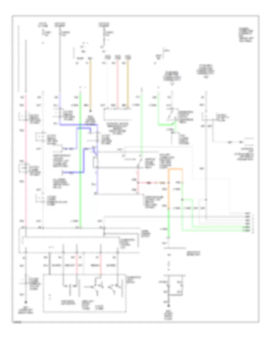
Headlamps & Fog Lamps Wiring Diagram, Canada (1 of 2) for Acura RL 2010
List of elements for Headlamps & Fog Lamps Wiring Diagram, Canada (1 of 2) for Acura RL 2010:
- 10a
- 2) auto 3) head
- Auto lt sig
- Auto lt sio
- Auto lt sip
- Automatic lighting sensor/sunlight sensor (front center of dash)
- B-can
- B12
- B17
- Base
- Body controller area network transceiver
- Combination light switch
- Combination switch control unit
- Computer data lines system
- D11
- D12
- D14
- Dimmer switch 0) low 1) high 2) passing
- Drive circuit
- Driver's under-dash fuse/relay box (behind left kick panel)
- Except base
- Exterior lights system
- Fog light indicator indicator
- Fog light switch 0) off 1) on
- Fuse 21
- Fuse 3
- Fuse 7
- G501 (under left side of dash)
- G502 (under left side of dash)
- G601 (at left side of floor)
- Gauge control module
- H/l backup
- Headlight switch 0) off 1) park
- High beam indicator
- Hot at all times
- Hot in on or start
- Ig1
- J/c c305 (under left side of dash)
- J/c c507 (behind left side of dash)
- J/c c510 (behind left side of dash)
- J/c c512 (behind left side of dash)
- J/c c519 (behind middle of dash)
- J/c c520 (under steering column cover)
- Lights on indicator
- Lights on/fog light brightness control & dimming circuit
- Micu
- N28
- Not used
- P14
- P27
- P30
- Pnk
- Red
- Sg-1
- Sg-2
- Vbu
- Wiper/ washer switch
- X34
- X35
Headlamps & Fog Lamps Wiring Diagram, Canada (2 of 2) for Acura RL 2010
List of elements for Headlamps & Fog Lamps Wiring Diagram, Canada (2 of 2) for Acura RL 2010:
- (not used)
- 10a
- 15a
- Auxiliary under-hood relay box (left side of engine compt)
- Control block
- Drl relay
- F14
- F15
- Fog light relay
- Fuse 1
- Fuse 11
- Fuse 3
- Fuse 5
- Fuse 6
- G201
- G301 (behind left side of front bumper)
- H10
- H11
- H12
- Hid unit
- High beam
- High beam headlight relay
- Hot at all times
- J/c c202 (behind right side of dash)
- Left fog light
- Left headlight
- Low beam
- Low beam headlight relay
- Red
- Relay control module
- Right fog light
- Right headlight
- Under-hood fuse/relay box (left rear of engine compt)
Headlamps & Fog Lamps Wiring Diagram, USA (1 of 2) for Acura RL 2010
List of elements for Headlamps & Fog Lamps Wiring Diagram, USA (1 of 2) for Acura RL 2010:
- (under left side of dash)
- 10a
- 2) auto 3) head
- Auto lt sig
- Auto lt sio
- Auto lt sip
- Automatic lighting sensor/sunlight sensor (front center of dash)
- B-can
- B12
- B14
- B17
- Body controller area network transceiver
- Combination light switch
- Combination switch control unit
- Computer data lines system
- D11
- D12
- D14
- Dimmer switch 0) low 1) high 2) passing
- Drive circuit
- Driver's under-dash fuse/relay box (behind left kick panel)
- Drl control unit
- Exterior lights system
- Fog light indicator indicator
- Fog light switch 0) off 1) on
- Fuse 21
- Fuse 3
- Fuse 7
- G401 (under right side of dash)
- G501 (under left side of dash)
- G502 (under left side of dash)
- G601 (at left side of floor)
- Gauge control module
- H/l backup
- Headlight switch 0) off 1) park
- High beam indicator
- Hot at all times
- Hot in on or start
- Ig1
- J/c c305 (w/ technology package, cmbs/pax package (under left side of dash)
- J/c c306 (under left side of dash)
- J/c c507 (behind left side of dash)
- J/c c510 (behind left side of dash)
- J/c c512 (behind left side of dash)
- J/c c519 (behind middle of dash)
- J/c c520 (under steering column cover)
- Lights on indicator
- Lights on/fog light brightness control & dimming circuit
- Micu
- N28
- N30
- N34
- Not used
- P14
- P27
- P30
- Parking brake switch (under left side of dash)
- Pnk
- Red
- Sg-1
- Sg-2
- Vbu
- Wiper/ washer switch
- X34
- X35
Headlamps & Fog Lamps Wiring Diagram, USA (2 of 2) for Acura RL 2010
List of elements for Headlamps & Fog Lamps Wiring Diagram, USA (2 of 2) for Acura RL 2010:
- (not used)
- 10a
- 15a
- Control block
- F14
- F15
- Fog light relay
- Fuse 1
- Fuse 11
- Fuse 3
- Fuse 5
- Fuse 6
- G201
- G301 (behind left side of front bumper)
- H10
- H11
- H12
- Hid unit
- High beam
- High beam headlight relay
- Hot at all times
- J/c c202 (behind right side of dash)
- Left fog light
- Left headlight
- Low beam
- Low beam headlight relay
- Red
- Relay control module
- Right fog light
- Right headlight
- Under-hood fuse/relay box (left rear of engine compt)
Headlamps Leveling Wiring Diagram for Acura RL 2010
List of elements for Headlamps Leveling Wiring Diagram for Acura RL 2010:
- (under left side of dash) dlc (data link connector)
- 2) auto 3) head
- 7.5a
- B-up h/l lev
- B12
- Combination light switch
- Combination switch control unit
- Computer
- Data lines system
- Driver's under-dash fuse/relay box (behind left kick panel)
- E11
- Exterior lights system
- Fuse 29
- G401 (under right side of dash)
- G501 (under left side of dash)
- Gnd
- Headlamps & fog lamps circuit
- Headlight leveling control unit (under left side of dash)
- Headlight switch 0) off 1) park
- Hot in on or start
- Ig1
- J/c c306 (under left side of dash)
- J/c c508 (behind left side of dash)
- J/c c511 (behind left side of dash)
- J/c c512 (behind left side of dash)
- J/c c520 (under steering column cover)
- Left headlight leveling motor (behind left headlight assembly)
- Pcm (under middle of dash)
- Pnk
- Red
- Right headlight leveling motor (behind right headlight assembly)
- Scs
- Sig
- Suspension stroke sensor (under left rear of vehicle)
- Vss
- Vssout
- Wiper/ washer switch
- Wiper/washer system
- X20
HORN
Horn Wiring Diagram for Acura RL 2010
List of elements for Horn Wiring Diagram for Acura RL 2010:
- (under left side of dash)
- Adaptive front lighting control unit (under left side of dash)
- B-can
- C14
- Cable reel (b: on steering column) (c: on steering wheel)
- Control block
- Cruise control combination switch
- D11
- Distance switch (usa: cmbs/ pax package; canada: premium package)
- Driver's under-dash fuse/relay box (behind left kick panel)
- Fuse 13 15a
- High horn (behind middle of front bumper)
- Horn relay
- Horn switch
- Hot at all times
- J/c c305
- Low horn (behind middle of front bumper)
- Micu
- Nca
- Red
- Relay control module
- Steering wheel
- Under-hood fuse/relay box (left rear of engine compt)
- Usa: technology package, cmbs/ pax package; canada: premium package
- W/ base
INSTRUMENT CLUSTER
Instrument Cluster Wiring Diagram (1 of 2) for Acura RL 2010
List of elements for Instrument Cluster Wiring Diagram (1 of 2) for Acura RL 2010:
- 10v regulator
- 5v regulator
- A/t gear position detection circuit
- A/t gear position indicator brightness control & dimming circuit
- A/t gear position indicator drive circuit
- A10
- A11
- A12
- A13
- A14
- A15
- A16
- A17
- A18
- A19
- A20
- Abs ind
- Acc ind
- Afs ind
- Anti-lock brakes system
- Anti-theft & door locks systems
- B10
- B11
- B12
- B13
- B14
- B15
- B16
- B17
- B18
- B19
- B20
- B21
- B22
- B23
- B24
- B25
- B26
- B27
- B28
- Beeper
- Body controller area network
- Brake system ind
- Charging system ind
- Cmbs ind
- Compulsory turning-off circuit
- Compulsory turning-on circuit
- Computer data lines system
- Cruise control dimming circuit
- Cruise control main switch ind (usa: base, technology package; canada: base)
- Cruise control system
- Dial brightness control & dimming circuit
- Door locks system
- Drive circuit
- Ecps ind
- Electronic power steering system cruise control system
- Engine coolant temperature gauge
- Exterior lights system
- Fail safe circuit
- Fast controller area network
- Fog lights ind
- Fuel gauge
- G501 (under left side of dash)
- Gauge control module
- Green ind
- High beam ind
- Immobilizer system ind
- Information ind
- Interior lights system
- Interior lights systems
- Keyless access ind
- Lcd back light
- Lcd brightness control & dimming circuit
- Led light
- Left turn signal ind
- Lights on ind
- Lights on/fog light brightness control & dimming circuit
- Low fuel ind
- Low oil pressure ind
- Low tire pressure ind
- Mil ind
- Multi- information display (mid) unit
- Navigation system
- Orange ind
- Pnk
- Pointer brightness control & dimming circuit
- Red
- Right turn signal ind
- Seat belt reminder ind
- Security ind
- Security ind blinking circuit
- Sh-awd ind
- Shift ind
- Shift indicator brightness control & dimming circuit
- Side air bag cut-off ind
- Speedo- meter
- Srs ind
- Srs ind circuit
- Tachometer
- Tpms ind, door & trunk open monitor
- Transceiver
- Transmissions system
- Usa: cmbs/pax package & canada: premium package
- Usa: cmbs/pax package, technology package & canada: premium package
- Vsa activation ind
- Vsa system ind
- Warning drive circuit
- Wiper/washer system exterior lights system
Instrument Cluster Wiring Diagram (2 of 2) for Acura RL 2010
List of elements for Instrument Cluster Wiring Diagram (2 of 2) for Acura RL 2010:
- (under left side of dash) j/c c305
- A14
- A28
- As door sw
- B-can
- B11
- B12
- Base
- Brake fluid level switch (integral to brake fluid reservoir cap)
- C17
- Cable reel (connector b: on steering column) (connector c: on steering wheel)
- Can
- Can h
- Can l
- Computer data lines system
- Control block
- Cpsw
- D11
- Door sw
- Dr door sw
- Driver's door lock actuator/ knob switch/ door switch
- Driver's door switch
- Driver's mpcs unit
- Driver's under-dash fuse/relay box (behind left kick panel)
- E15
- E26
- Except base
- Front passenger's door lock actuator/knob switch/door switch
- Front passenger's door switch
- Front passenger's mpcs unit
- Fuel gauge sending unit
- Fuel tank unit (under left side of rear seat)
- Fuse 21 10a
- Fuse 7 10a
- G401 (under right side of dash)
- G506 (behind glove box)
- G601 (at left side of floor)
- G651 (at right side of floor)
- Hot at all times
- Hot in on or start
- Immobilizer control unit- receiver (on right side of steering column)
- J/c c507 (behind left side of dash)
- J/c c510 (behind left side of dash)
- J/c c512 (behind left side of dash)
- J/c c757 (in driver's door)
- J/c c775 (in front passenger's door)
- J/c c783 (in left rear door)
- J/c c793 (in right rear door)
- Keyless access control unit (under left side of dash)
- Left rear door lock actuator/ knob switch/ door switch (rear of left rear door)
- Left rear door switch
- Left rear power window switch
- Micu
- N22
- N30
- N34
- Next switch
- Oil pressure switch (right side of engine)
- Parking brake switch (under left side of dash)
- Pcm (under middle of dash)
- Pnk
- Red
- Relay control module
- Right rear door lock actuator/ knob switch/ door switch (rear of right rear door)
- Right rear door switch
- Right rear power window switch
- Secondary fuel gauge sending unit (under right side of rear seat)
- Select/ reset switch
- Select/reset/ information switch
- Steering wheel
- Uart
- Under-hood fuse/relay box (left rear of engine compt)
- X34
- X35
INTERIOR LIGHTS
Courtesy Lamps Wiring Diagram (1 of 3) for Acura RL 2010
List of elements for Courtesy Lamps Wiring Diagram (1 of 3) for Acura RL 2010:
- (at left side of floor) g601
- (behind left side of dash)
- (behind left side of dash) j/c c509
- (behind middle of dash) j/c c516
- (in driver's door)
- (in driver's door) j/c c756
- (in driver's door) j/c c757
- (not used)
- (under left side of
- 10a
- 7.5a
- A13
- A14
- A15
- A26
- A27
- A28
- A33
- A36
- A37
- Active noise control unit (right side of trunk)
- All times
- B-can
- Computer data lines system
- Courtesy
- Dash)
- Door sw (dr)
- Dr pocket ill
- Driver's door courtesy light
- Driver's door inner handle light
- Driver's door lock actuator/ knob switch/ door switch
- Driver's door lock switch
- Driver's door outer handle light/touch sensor
- Driver's door pocket light
- Driver's door switch 1) door
- Driver's footwell light
- Driver's mpcs unit (in driver's door)
- Driver's under-dash fuse/relay box (behind left kick panel)
- Driving position memory switch
- Foot lt
- Front passenger's footwell light
- Fuel ind
- Fuse 6
- Fuse 7
- G601 (at left side of floor)
- G701 (left side of trunk)
- Hot at
- Inn hand ill
- Intr lt
- J/c c512
- J/c c514
- J/c c607 (behind left kick panel)
- J/c c608 (behind left kick panel)
- J/c c662 (behind rear seat)
- J/c c755 (in driver's door)
- J/c c756 (in driver's door)
- J/c c757
- J/c c757 (in driver's door)
- Map lt off
- Mem ill
- Memory system
- Micu
- N15
- Open
- Out handl ill
- Pnk
- Q12
- Red
- To driver's under-dash fuse/relay box (diagram 2 0f 3)
- Trunk lid latch switch/opener solenoid 1) trunk open
- Trunk lid light switch
- Trunk lid opener/ fuel lid opener switch
- Trunk light a
- Trunk light b
- Uart
- Vbu
- Vbu 1
- Vbu 2
- X35
Courtesy Lamps Wiring Diagram (2 of 3) for Acura RL 2010
List of elements for Courtesy Lamps Wiring Diagram (2 of 3) for Acura RL 2010:
- (at left side of floor) g601
- (in left rear door) j/c c783
- (in right rear door) j/c c793
- 5v regulator
- Computer data lines system
- Control circuit
- Courtesy
- Door sw
- Driver's under-dash fuse/relay box (behind left kick panel)
- From driver's under-dash fuse/relay box (diagram 1 0f 3)
- Front individual map lights
- G601 (at left side of floor)
- G651 (at right side of floor)
- Inn handle ill
- Interior light switch (door)
- Interior light switch (off)
- Interior light switch (on)
- J/c c610 (base of left "b" pillar)
- J/c c783 (in left rear door)
- J/c c793 (in right rear door)
- Left front individual map light
- Left front individual map light switch
- Left rear door courtesy light
- Left rear door inner handle light
- Left rear door lock actuator/ knob switch/ door switch
- Left rear door switch 1) door
- Left rear power window switch
- Open
- Pnk
- Red
- Right front individual map light
- Right front individual map light switch
- Right rear door courtesy light
- Right rear door inner handle light
- Right rear door lock actuator/ knob switch/ door switch
- Right rear door switch 1) door open
- Right rear power window switch
- Roof console
- Sgnd
- Uart
- Vbu
Courtesy Lamps Wiring Diagram (3 of 3) for Acura RL 2010
List of elements for Courtesy Lamps Wiring Diagram (3 of 3) for Acura RL 2010:
- (behind left kick panel) driver's under dash fuse/relay box
- (behind middle of dash)
- (in front passenger's door)
- (in front passenger's door) j/c c775
- A19
- A21
- A23
- A28
- As pocket ill
- Computer data lines system
- Courtesy
- D13
- Door sw (as)
- Driver's under-dash fuse/relay box (behind left kick panel)
- Driver's vanity mirror light
- Front
- Front passen- ger's vanity mirror light
- Front passenger's door courtesy light
- Front passenger's door inner handle light
- Front passenger's door lock actuator/ knob switch/ door switch
- Front passenger's door outer handle light/ touch sensor
- Front passenger's door pocket light
- Front passenger's door switch 1) door
- G506 (behind glove box)
- G601 (at left side of floor)
- Inn handl ill
- J/c c515
- J/c c775
- J/c c776 (in front passenger's door)
- J/c c852 (in left front of roof)
- Left rear individual map light
- Left rear individual map light switch
- Open
- Out handl ill
- Passenger's mpcs unit (in front passenger's door)
- Passenger's under-dash fuse/relay box (behind right kick panel)
- Pnk
- Rear individual map lights
- Red
- Right rear individual map light
- Right rear individual map light switch
- Uart
- Vbu
- Vbu 2
Entry Light Timer Wiring Diagram for Acura RL 2010
List of elements for Entry Light Timer Wiring Diagram for Acura RL 2010:
- A11
- A13
- A21
- A22
- A28
- As door sw
- Bcan
- Can
- Computer data lines system
- Control unit
- D13
- Door sw
- Door switch
- Driver's door key cylinder switch
- Driver's door lock actuator/ knob switch/ door switch
- Driver's door switch
- Driver's mpcs unit (in driver's door)
- Driver's under-dash fuse/relay box (behind left kick panel)
- Front
- Front passenger's door lock actuator/ knob switch/ door switch
- Front passenger's mpcs unit (in front passenger's door)
- Fuse 10a
- Fuse 7.5a
- G501 (under left side of dash)
- G502 (under left side of dash)
- G506 (behind glove box)
- G601 (at left side of floor)
- G651 (at right side of floor)
- H14
- Hot at all times
- Ignition key light
- Ignition key switch
- Ignition switch control unit
- J/c c512 (behind left side of dash)
- J/c c514 (under left side of dash)
- J/c c515 (behind middle of dash)
- J/c c516 (behind middle of dash)
- J/c c520 (under steering column cover)
- J/c c610 (base of left "b" pillar)
- J/c c662 (behind rear seat)
- J/c c757 (in driver's door)
- J/c c775 (in front passenger's door)
- J/c c783 (in left rear door)
- J/c c793 (in right rear door)
- Key
- Key lock
- Key lt
- Key unlock
- Keyless access control unit (under left side of dash)
- Left rear door lock actuator/ knob switch/ door switch (rear of left rear door)
- Left rear door switch
- Left rear power window switch
- Lock
- Micu
- N15
- Passenger's
- Passenger's under-dash fuse/relay box (behind right kick panel)
- Red
- Right rear door lock actuator/ knob switch/ door switch (rear of right rear door)
- Right rear door switch
- Right rear power window switch
- Sg 1 p1
- Uart
- Unlock
- Vbu
- X18
- X35
Instrument Illumination Wiring Diagram (1 of 3) for Acura RL 2010
List of elements for Instrument Illumination Wiring Diagram (1 of 3) for Acura RL 2010:
- (at base of right "b" pillar) j/c c661
- (at left side of floor)
- (at right side of floor) g651
- (in left "c" pillar)
- (not used)
- (under left side of dash)
- B12
- B25
- B26
- Brightening switch
- C792
- Cmbs/pax package; canada: premium package
- Combination light switch
- Combination switch control unit
- Control block
- Dash lights brightness controller
- Dimming switch
- Driver's seat ventilation control unit (usa: technology package; cmbs/pax package canada: premium package)
- Driver's under-dash fuse/relay box (behind left kick panel)
- Front passenger's seat ventilation control unit (usa: technology package, cmbs/pax package; canada: premium package)
- Fuse 4 15a
- Fuse 7 7.5a
- G10
- G501
- G501 (under left side of dash)
- G601
- G602
- Gauge control module
- H13
- H14
- Headlight switch 0) off 1) park 2) auto 3) head
- Headlights system
- Hot at all times
- J/c c507 (behind left side of dash)
- J/c c520 (under steering column cover)
- J/c c612
- J/c c833 (middle of trunk)
- J19
- Left brake light/taillight
- Left front parking light
- Left license plate light
- N31
- Navigation unit (in trunk, below left side of package tray)
- Passenger's under-dash fuse/relay box (behind right kick panel)
- Pnk
- Red
- Relay control module
- Right brake light/taillight
- Right front parking light
- Right license plate light
- Taillight relay
- Under-hood fuse/relay box (left rear of engine compt)
- Usa: technology package
- Usa: technology package,
- W/ base
- Wiper/washer switch
Instrument Illumination Wiring Diagram (2 of 3) for Acura RL 2010
List of elements for Instrument Illumination Wiring Diagram (2 of 3) for Acura RL 2010:
- (2)
- (8 leds)
- (under left side of dash) j/c c514
- Ambient lights (2)
- Audio remote switch
- B16
- B17
- Cable reel (b: on steering column) (c: on steering wheel)
- Cmbs/pax package; canada: premium package
- Courtesy lamps circuit
- Cruise control combination switch
- Distance switch (usa:cmbs/ pax package; canada: premium package)
- Driver's seat heater switch
- Driver's under-dash fuse/relay box (behind left kick panel)
- Fuse 21 10a
- Fuse 7 10a
- Headlight washer switch (canada)
- Hfl switch
- Hot at all times
- Hot in on or start
- J/c c510 (behind left side of dash)
- J/c c512 (behind left side of dash)
- J/c c513 (behind left side of dash)
- J/c c609 (behind left kick panel)
- J21
- Moonroof switch
- Pnk
- Power mirror switch
- Rear individual map lights
- Red
- Roof console
- Select/ reset/ information switch
- Steering wheel
- Switch lights (2)
- Usa: base
- Usa: technology package,
- Voice control switch
- Vsa off switch (w/ base) afs off/ vsa off/ switch (usa: technology package) afs off/ vsa off/ mbs off switch (usa: cmbs/pax package; canada: premium package)
- X21
- X34
- X35
Instrument Illumination Wiring Diagram (3 of 3) for Acura RL 2010
List of elements for Instrument Illumination Wiring Diagram (3 of 3) for Acura RL 2010:
- (behind middle of dash) j/c c515
- A/t gear position indicator panel light
- A19
- Audio unit
- Canada
- Climate control unit
- Cmbs/pax package; canada: premium package
- Coin pocket light
- Console box light
- Driver's seat ventilation switch
- Front passenger's seat heater switch
- Front passenger's seat ventilation switch
- G503 (under middle of dash)
- G506 (behind glove box)
- G602 (in left "c" pillar)
- Glove box light
- Hazard warning switch/front passenger's air bag cut- off indicator
- J/c c516 (behind middle of dash)
- J/c c523
- J/c c523 (under center console)
- J/c c524 (behind middle of dash)
- J/c c527
- J/c c552
- Left rear seat heater switch (canada)
- Navigation display unit
- Rear accessory power socket
- Red
- Right rear seat heater switch (canada)
- Transmission gear selection switch/ park pin switch/ a/t gear position indicator panel light
- Usa: technology package,
- Usa: w/ base
MEMORY SYSTEMS
Memory Systems Wiring Diagram (1 of 4) for Acura RL 2010
List of elements for Memory Systems Wiring Diagram (1 of 4) for Acura RL 2010:
- (at left side of floor) g601
- (behind middle of dash) j/c c521
- Atp
- Atpp
- B-can
- Back
- Bus2
- Computer data lines system
- Driver power seat control unit (under driver's seat)
- Driver's power seat adjustment switch
- Driver's power seat front up-down motor/positon sensor (under driver's seat)
- Driver's power seat rear up-down motor/positon sensor (under driver's seat)
- Driver's power seat recline motor/positon sensor (in driver's seat back)
- Driver's power seat slide/motor position sensor (under driver's seat)
- Driver's under-dash fuse/relay box (behind left kick panel)
- F11
- F13
- Fhdn
- Fhm +
- Fhm -
- Fhse
- Fhup
- Front up- down switch
- Fuse 14 20a
- Fuse 16 20a
- Fuse 21 10a
- Fuse 7 10a
- Fwd
- G601 (at left side of floor)
- Head
- Hot at all times
- Hot in on or start
- Hrm+
- Hrm-
- Ig1
- Ign
- J/c c608 (behind left kick panel)
- J/c c610 (base of left "b" pillar)
- J13
- Micu
- P16
- Pcm (under middle of dash)
- Pg1
- Pg2
- Pnk
- Rear up- down switch
- Recline switch
- Red
- Refw
- Rem +
- Rem -
- Rerw
- Rese
- Rhdn
- Rhm +
- Rhm -
- Rhse
- Rhup
- Scom
- Seats system
- Seg
- Sensor
- Slfw
- Slide switch
- Slm+
- Slm-
- Slrw
- Slse
- Svcc
- Vbu
- Vmp1
- Vmp2
- X34
- X35
Memory Systems Wiring Diagram (2 of 4) for Acura RL 2010
List of elements for Memory Systems Wiring Diagram (2 of 4) for Acura RL 2010:
- (behind center rear seat headrest) center rear headrest actuator
- (behind left rear seat headrest) left rear headrest actuator
- (behind right rear seat headrest) right rear headrest actuator
- (in left "c" pillar) g602
- B-can
- Computer data lines system
- Driver's mpcs unit (in driver's door)
- Driving position memory switch
- Driving position memory switch light
- G601 (at left side of floor)
- Hlse
- Interior lights system
- J/c c756 (in driver's door)
- J/c c757 (in driver's door)
- Left power mirror (in driver's door)
- Left/right motor
- Mem ill
- Mem ind 1
- Mem ind 2
- Mem pos 1
- Mem pos 2
- Mem set
- Memo button
- Mir com
- Mir lr
- Mir ud
- Pnk
- Position 1 button
- Position 1 indicator
- Position 2 button
- Position 2 indicator
- Power rear headrest switch
- Red
- Roof console
- Swing
- Tilt
- Uart
- Up/down motor
- Vbu
- Vbu1
- Vlse
- Vref
Memory Systems Wiring Diagram (3 of 4) for Acura RL 2010
List of elements for Memory Systems Wiring Diagram (3 of 4) for Acura RL 2010:
- (behind glove box) g506
- (behind left side of dash) j/c c512
- (under steering column cover) j/c c520
- Bus
- Computer data lines system
- D13
- Driver's under-dash fuse/relay box (behind left kick panel)
- Front passenger's mpcs unit (in front passenger's door)
- Fuse 25 20a
- Fuse 26 20a
- G501 (under left side of dash)
- G503 (under middle of dash)
- G506 (behind glove box)
- H11
- Hot at all times
- Hrse
- Ign
- J/c c510 (behind left side of dash)
- J/c c515 (behind middle of dash)
- J/c c519 (under left side of dash)
- J/c c775 (in front passenger's door)
- J/c c776 (in front passenger's door)
- J10
- Left/right motor
- Mir com
- Mir lr
- Mir ud
- N12
- Passenger's under-dash fuse/relay box (behind right kick panel)
- Pnk
- Power telescopic steering motor/ position sensor (under steering column cover)
- Power tilt motor/ position sensor (under steering column cover)
- Power tilt/ telescopic steering control unit (under left side of dash)
- Power tilt/ telescopic steering switch
- Red
- Right power mirror
- Seg
- Svcc
- Swbat
- Swg
- Swing
- Telescopic switch
- Tem +
- Tem -
- Tesa
- Tesb
- Tilt
- Tilt switch
- Tim +
- Tim -
- Tisa
- Tisb
- Uart
- Up/down motor
- Vbu
- Vmp1
- Vmp2
- Vref
- Vrse
Memory Systems Wiring Diagram (4 of 4) for Acura RL 2010
List of elements for Memory Systems Wiring Diagram (4 of 4) for Acura RL 2010:
- Atp-r
- B-can
- Computer data lines system
- Down
- Driver's under-dash fuse/relay box (behind left kick panel)
- G101 (top front of engine)
- G501 (under left side of dash)
- Interior lights system
- J/c c106 (top of transmission)
- J/c c521 (behind middle of dash)
- Left
- Micu
- Mirror dn
- Mirror l
- Mirror lt
- Mirror r
- Mirror rt
- Mirror up
- N21
- P10
- P11
- P20
- P22
- P25
- P26
- Pnk
- Power mirror switch
- Power mirror switch lights
- Right
- Transmission range switch (on transaxle)
- X28
NAVIGATION
Home Link Remote Control Wiring Diagram for Acura RL 2010
List of elements for Home Link Remote Control Wiring Diagram for Acura RL 2010:
- Driver's under-dash fuse/relay box (behind left kick panel)
- Fuse 7.5a
- G601 (at left side of floor)
- Homelink unit
- Hot at all times
- Interior lights system
- J/c c852 (in left front of roof)
- Power tops system
- Roof console
- Sw 1
- Sw 2
- Sw 3
Navigation Wiring Diagram, Except USA (1 of 7) for Acura RL 2010
List of elements for Navigation Wiring Diagram, Except USA (1 of 7) for Acura RL 2010:
- 5v gnd
- Acc
- Acc cut relay
- Active noise control circuit
- Air conditioning system
- Amp shld
- Audio hvac sub display unit-clock
- Audio unit
- Auxiliary under-dash fuse/relay box (under left side of dash)
- Blank
- Bose bus +
- Bose bus -
- Bose bus shld
- Clk-a/c
- Clock
- Data
- Diag
- Door locks system
- Driver's under-dash fuse/relay box (behind left kick panel)
- Fr ctr +
- Fr ctr -
- Fr l +
- Fr l -
- Fr r +
- Fr r -
- Fuse 10a
- G504 (under middle of dash)
- Gnd
- Hfl mute
- Hot in acc or on
- Ill +
- Ill -
- Ims1
- Ims2
- Interior lights system
- J/c c508 (behind left side of dash)
- J11
- Lcd bl +
- Lcd bl -
- Load
- N36
- Navi scty
- Nca
- Pnk
- Power distribution system
- Pre amp shld
- Radio +b
- Red
- Remote on
- Remote sw
- Remote sw gnd
- Rr l +
- Rr l -
- Rr r +
- Rr r -
- Seg test
- Shield
- So-ac
- Stereo amplifier (right side of trunk)
- Sub +
- Sub -
Navigation Wiring Diagram, Except USA (2 of 7) for Acura RL 2010
List of elements for Navigation Wiring Diagram, Except USA (2 of 7) for Acura RL 2010:
- (behind middle of dash) j/c c524
- Audio remote switch
- B10
- B18
- Back button
- C10
- C17
- C18
- C20
- Cable reel (b: on steering column) (c: on steering wheel)
- Channel down switch
- Channel up switch
- D17
- Driver's under-dash fuse/relay box (behind left kick panel)
- Fuse 7.5a
- Hfl back button
- Hfl switch
- Hfl talk button
- Hot at all times
- Interior lights system
- J/c c661 (at base of right "b" pillar)
- Mode switch
- N11
- Nca
- Passenger's under-dash fuse/relay box (behind right kick panel)
- Steering wheel
- Talk button
- Voice control switch
- Volume down switch
- Volume up switch
Navigation Wiring Diagram, Except USA (3 of 7) for Acura RL 2010
List of elements for Navigation Wiring Diagram, Except USA (3 of 7) for Acura RL 2010:
- (in left "c" pillar) j/c c612
- (under right side of dash) j/c c528
- Acc
- Audio l+
- Audio l-
- Audio r+
- Audio r-
- Audio sh
- B sig1
- B-can
- C sig1
- Computer data lines system
- Driver's under-dash fuse/relay box (behind left kick panel)
- Ecu bus+
- Ecu bus-
- Fuse 10a
- G sig 1
- G506 (behind glove box)
- G601 (at left side of floor)
- G602 (in left "c" pillar) interior lights system
- G651 (at right side of floor)
- Ga-net bus sh
- Ga-net bus+
- Ga-net bus-
- Gnd
- Gnd sig1
- Gnd1
- Handsfreelink control unit (behind right kick panel)
- Hfl mute
- Hfl strg sw
- Hfl/ navigation microphone
- Hip-navi mic+
- Hip-navi mic-
- Hip/navi comm sh
- Hip/navi comm1
- Hip/navi comm2
- Hip/navi comm3
- Hip/navi comm4
- Hot at all times
- Ill+
- Interface dial
- J/c c512 (behind left side of dash)
- J/c c515 (behind middle of dash)
- J/c c527
- J/c c663 (behind rear seat)
- Jog
- Mic +
- Mic -
- Mic sh
- Mic+
- Mic-
- Micu
- Navigation display unit
- Nca
- P12
- R sig 1
- Radio sw
- Red
- Roof console
- Security+
- Security-
- Sh ecu bus
- Sh jog
- Sh sig1
- Telm sig sh
- Telm sig+
- Telm sig-
- X35
Navigation Wiring Diagram, Except USA (4 of 7) for Acura RL 2010
List of elements for Navigation Wiring Diagram, Except USA (4 of 7) for Acura RL 2010:
- (in left "c" pillar) g602
- (in rear of roof) g801
- (under middle of dash) pcm
- Ac-clk
- Ac-si
- Ac-so
- Acc
- Air conditioning system
- Audio l+
- Audio l-
- Audio r+
- Audio r-
- Audio sh
- B sig 1
- Back lt
- C sig 1
- Can-h
- Can-l
- Computer data lines system
- Diag+
- Diag-
- E11
- Ecu bus+
- Ecu bus-
- Exterior lights system
- G sig 1
- Ga-net bus
- Ga-net bus sh
- Ga-net bus-
- Gnd
- Gnd sig 1
- Ill+
- Input
- Interior lights system
- J/c c512 (behind left side of dash)
- J/c c616 (in left "c" pillar)
- Jog
- Navigation service check connector (under navigation unit)
- Navigation unit (in trunk, below left side of package tray)
- Nca
- R sig 1
- Red
- Sh ecu bus
- Sh jog
- Sh sig 1
- Sys 0n
- Vsp
- Vss out
- Xm antenna
- Xm receiver (left side of trunk)
Navigation Wiring Diagram, Except USA (5 of 7) for Acura RL 2010
List of elements for Navigation Wiring Diagram, Except USA (5 of 7) for Acura RL 2010:
- Am signal main window antenna
- Am/fm main antenna amplifier (in right "c" pillar)
- Am/fm sub-antenna amplifier
- Antenna sub-lead connector (behind right kick panel)
- Audio l+
- Audio l-
- Audio r+
- Audio r-
- Audio sh
- Audio unit
- Aux det
- Aux gnd
- Aux l-ch
- Aux r-ch
- Aux sh gnd
- Aux sig gnd
- Auxiliary jack assembly
- Fm signal main window antenna
- Fm signal sub-window antenna
- Ga-net bus sh
- Ga-net bus+
- Ga-net bus-
- Gnd
- J/c c525 (behind middle of dash)
- J/c c526 (behind middle of dash)
- J/c c615 (in left "c" pillar)
- Nca
- Rear window
- Red
- Sh (am/fm)
- Sig
- Swd +b
- Sys on
Navigation Wiring Diagram, Except USA (6 of 7) for Acura RL 2010
List of elements for Navigation Wiring Diagram, Except USA (6 of 7) for Acura RL 2010:
- Amplifier
- Audio l+
- Audio l-
- Audio r+
- Audio r-
- Audio sh
- Camera adpt
- Camera gnd
- Camera sh
- Camera v
- Ga-net bus sh
- Ga-net bus+
- Ga-net bus-
- Gnd
- Gps antenna (middle of rear shelf)
- Hfl comm sh
- Hfl comm1
- Hfl comm2
- Hfl comm3
- Hfl comm4
- J/c c509 (behind left side of dash)
- J/c c528 (under right side of dash)
- J/c c614 (in left "c" pillar)
- Mic sig+
- Mic sig-
- Navigation system
- Navigation unit (in trunk, below left side of package tray)
- Nca
- Rc gnd
- Rc vcc
- Red
- Rgl +
- Rgl gnd
- Rgl sh
- Sh (gps)
- Sh mic
- Sig (gps)
- Strg sw
- Sys on
- Usb
- Usb adapter unit
- Usb data+
- Usb data-
- Usb gnd
- Usb jack
- Usb sh
- Usb vbus
Navigation Wiring Diagram, Except USA (7 of 7) for Acura RL 2010
List of elements for Navigation Wiring Diagram, Except USA (7 of 7) for Acura RL 2010:
- Active noise
- Active noise control circuit
- Control circuit
- Ctr sp +
- Ctr sp -
- Driver's door speaker
- F +
- F -
- Fl sp+
- Fl sp-
- Fr sp +
- Fr sp -
- Front center speaker
- Front passenger's door speaker
- Fuse 30a
- G652 (in right "c" pillar)
- Gnd
- Hot at all times
- Left rear door speaker
- Left rear twiddler
- Left tweeter
- Mic r in +
- Mic r in -
- Passenger's under-dash fuse/relay box (behind right kick panel)
- Pnk
- R +
- R -
- Radio sw +b
- Red
- Rg-l +
- Rg-l gnd
- Right rear door speaker
- Right rear twiddler
- Right tweeter
- Rl sp+
- Rl sp-
- Rl twd +
- Rl twd -
- Rr sp +
- Rr sp -
- Rr twd +
- Rr twd -
- Stereo amplifier (right side of trunk)
- Subw sp+
- Subw sp-
- Subwoofer
- Telm sig+
- Telm sig-
Navigation Wiring Diagram, USA (1 of 7) for Acura RL 2010
List of elements for Navigation Wiring Diagram, USA (1 of 7) for Acura RL 2010:
- 5v gnd
- A10
- A11
- A12
- A13
- A14
- A15
- A16
- A17
- A18
- A19
- A20
- A21
- A22
- A23
- A24
- A25
- A26
- Ac-clk
- Ac-so
- Acc
- Acc cut relay
- Active noise control circuit
- Air conditioning system
- Amp shld
- Audio hvac sub display unit-clock
- Audio unit
- Auxiliary under-dash fuse/relay box (under left side of dash)
- B10
- B11
- B12
- B13
- B14
- B15
- B16
- B17
- B18
- B19
- B20
- B21
- B22
- B23
- B24
- B25
- B26
- B27
- B28
- B29
- B30
- B31
- B32
- Blank
- Bose bus +
- Bose bus -
- Bose bus shld
- Clock
- Data
- Diag
- Door locks system
- Driver's under-dash fuse/relay box (behind left kick panel)
- Fr ctr +
- Fr ctr -
- Fr l +
- Fr l -
- Fr r +
- Fr r -
- Fuse 10a
- G504 (under middle of dash)
- Gnd
- Hfl mute
- Hot in acc or on
- Ill +
- Ill -
- Ims1
- Ims2
- Interior lights system
- J/c c508 (behind left side of dash)
- J11
- Lcd bl +
- Lcd bl -
- Load
- N36
- Navi scty
- Nca
- Pnk
- Power distribution system
- Pre amp shld
- Red
- Remote on
- Remote sw
- Remote sw gnd
- Rr l +
- Rr l -
- Rr r +
- Rr r -
- Seg test
- Shield
- Stereo amplifier (right side of trunk)
- Sub +
- Sub -
- Test
Navigation Wiring Diagram, USA (2 of 7) for Acura RL 2010
List of elements for Navigation Wiring Diagram, USA (2 of 7) for Acura RL 2010:
- (behind middle of dash) j/c c524
- Audio remote switch
- B10
- B18
- Back button
- C10
- C17
- C18
- C20
- Cable reel (b: on steering column) (c: on steering wheel)
- Channel down switch
- Channel up switch
- D17
- Driver's under-dash fuse/relay box (behind left kick panel)
- Fuse 7.5a
- Hfl back button
- Hfl switch
- Hfl talk button
- Hot at all times
- Interior lights system
- J/c c661 (at base of right "b" pillar)
- Mode switch
- N11
- Nca
- Passenger's under-dash fuse/relay box (behind right kick panel)
- Steering wheel
- Talk button
- Voice control switch
- Volume down switch
- Volume up switch
Navigation Wiring Diagram, USA (3 of 7) for Acura RL 2010
List of elements for Navigation Wiring Diagram, USA (3 of 7) for Acura RL 2010:
- (behind glove box) g506
- (in left "c" pillar) j/c c612
- (under right side of dash) j/c c528
- Acc
- Audio l+
- Audio l-
- Audio r+
- Audio r-
- Audio sh
- B sig1
- B-can
- Base
- C sig1
- Computer data lines system
- Driver's under-dash fuse/relay box (behind left kick panel)
- Ecu bus+
- Ecu bus-
- Except base
- Fuse 10a
- G sig 1
- G601 (at left side of floor)
- G602 (in left "c" pillar)
- G651 (at right side of floor)
- Ga-net bus sh
- Ga-net bus+
- Ga-net bus-
- Gnd
- Gnd sig1
- Gnd1
- Handsfreelink control unit (behind right kick panel)
- Hfl mute
- Hfl strg sw
- Hfl/ navigation microphone
- Hip-navi mic+
- Hip-navi mic-
- Hip/navi comm sh
- Hip/navi comm1
- Hip/navi comm2
- Hip/navi comm3
- Hip/navi comm4
- Hot at all times
- Hot in on or start
- Ill+
- Interface dial
- Interior lights system
- J/c c512 (behind left side of of dash)
- J/c c515 (behind middle of dash)
- J/c c527
- J/c c610 (base of left "b" pillar)
- J/c c663 (behind rear seat)
- Jog
- Mic +
- Mic -
- Mic sh
- Mic+
- Mic-
- Micu
- Navigation display unit
- Nca
- P12
- R sig 1
- Radio sw
- Red
- Roof console
- Security+
- Security-
- Sh ecu bus
- Sh jog
- Sh sig1
- Telm sig sh
- Telm sig+
- Telm sig-
- X35
Navigation Wiring Diagram, USA (4 of 7) for Acura RL 2010
List of elements for Navigation Wiring Diagram, USA (4 of 7) for Acura RL 2010:
- (in left "c" pillar) g602
- (in left "c" pillar) j/c c613
- A10
- A11
- A12
- A13
- A14
- A15
- A16
- A17
- A18
- A19
- A20
- A21
- A22
- A23
- A24
- A25
- A26
- A27
- A28
- A29
- A30
- A31
- A32
- Ac-clk
- Ac-si
- Ac-so
- Acc
- Acuralink control unit (xm receiver) (except base) (on left side of trunk)
- Acuralink reprogramming connector
- Air conditioning system
- Audio l+
- Audio l-
- Audio r+
- Audio r-
- B sig 1
- B-can
- B10
- B11
- B12
- B13
- B14
- B15
- B16
- B17
- B18
- B20
- B21
- B22
- B23
- B24
- B25
- B26
- B27
- B28
- B29
- B30
- B31
- B32
- Back lt
- C sig 1
- Can-h
- Can-l
- Computer data lines system
- Diag+
- Diag-
- E11
- Ecu bus+
- Ecu bus-
- Exterior lights system
- F-can h
- F-can l
- G sig 1
- G602 (in left "c" pillar)
- G801 (in rear of roof)
- Ga-net bus+
- Ga-net bus-
- Gnd
- Gnd sig 1
- Hfl comm sh
- Hfl comm1
- Hfl comm2
- Hfl comm3
- Hfl comm4
- Hft com 1
- Ig1
- Ill+
- Interior lights system
- J/c c512 (behind left side of dash)
- J/c c616 (in left "c" pillar)
- Jog
- Line out -
- Navi comm sh
- Navi comm1
- Navi comm2
- Navi comm3
- Navi comm4
- Navigation service check connector (under navigation unit)
- Navigation unit (in trunk, below left side of package tray)
- Nca
- Pcm (under middle of dash)
- R sig 1
- Red
- Sh ecu bus
- Sh jog
- Sh sig 1
- Vss out
- Xm antenna
Navigation Wiring Diagram, USA (5 of 7) for Acura RL 2010
List of elements for Navigation Wiring Diagram, USA (5 of 7) for Acura RL 2010:
- Alx det
- Am signal main window antenna
- Am/fm main antenna amplifier (in right "c" pillar)
- Am/fm sub- antenna amplifier
- Antenna sub-lead lead connector (behind right kick panel)
- Audio l+
- Audio l-
- Audio r+
- Audio r-
- Audio sh
- Audio unit
- Aux det
- Aux gnd
- Aux l ch
- Aux l-ch
- Aux r-ch
- Aux sh gnd
- Aux sig gnd
- Auxiliary jack assembly
- C10
- C11
- C12
- C13
- C14
- Fm signal main window antenna
- Fm signal sub-window antenna
- Ga-net-bus sh
- Ga-net-bus+
- Ga-net-bus-
- Gnd
- J/c c525 (behind middle of dash)
- J/c c526 (behind middle of dash)
- J/c c614 (in left "c" pillar)
- J/c c615 (in left "c" pillar)
- Nca
- Rear window
- Red
- Sh (am/fm)
- Sig
- Swd +b
- Sys on
Navigation Wiring Diagram, USA (6 of 7) for Acura RL 2010
List of elements for Navigation Wiring Diagram, USA (6 of 7) for Acura RL 2010:
- (or red)
- A10
- A11
- A12
- A13
- A14
- Amplifier
- Audio l+
- Audio l-
- Audio r+
- Audio r-
- Audio sh
- Base
- Bus sh
- Bus+
- Bus-
- C10
- C11
- C12
- C13
- C14
- C15
- C16
- Camara adpt
- Camara gnd
- Camara sh
- Camara v
- Except base
- G801 (in rear of roof)
- Ga-net bus sh
- Ga-net bus+
- Ga-net bus-
- Gnd
- Gps antenna (middle of rear shelf)
- Hip/hfl comm sh
- Hip/hfl comm1
- Hip/hfl comm2
- Hip/hfl comm3
- Hip/hfl comm4
- Input
- J/c c509 (behind left side of dash)
- J/c c528 (under right side of dash)
- Mic sig+
- Mic sig-
- Navigation unit (in trunk, below left side of package tray)
- Nca
- Rc gnd
- Rc vcc
- Rear camera circuit
- Red
- Rgl +
- Rgl gnd
- Rgl sh
- Sh (gps)
- Sh mic
- Sig (gps)
- Strg sw
- Sys 0n
- Sys on
- Usb
- Usb adapter unit
- Usb data+
- Usb data-
- Usb gnd
- Usb jack
- Usb sh
- Usb vbus
- Xm antenna
- Xm receiver (base) (left side of trunk)
Navigation Wiring Diagram, USA (7 of 7) for Acura RL 2010
List of elements for Navigation Wiring Diagram, USA (7 of 7) for Acura RL 2010:
- (in right "c" pillar)
- Active noise control circuit
- B10
- B11
- B12
- B13
- B14
- C10
- C11
- C12
- C13
- C14
- C15
- C16
- C17
- C18
- C19
- C20
- C21
- C22
- C23
- Ctr sp +
- Ctr sp -
- Driver's door speaker
- Fl sp+
- Fl sp-
- Fr sp +
- Fr sp -
- Front center speaker
- Front passenger's door speaker
- Fuse 30a
- G652
- Gnd
- Hot at all times
- Left rear door speaker
- Left rear twiddler
- Left tweeter
- Mic r in+
- Mic r in-
- Passenger's under-dash fuse/relay box (behind right kick panel)
- Pnk
- Rad sw +b
- Red
- Rg-l +
- Rg-l gnd
- Right rear door speaker
- Right rear twiddler
- Right tweeter
- Rl sp+
- Rl sp-
- Rl twd +
- Rl twd -
- Rr sp +
- Rr sp -
- Rr twd +
- Rr twd -
- Stereo amplifier (right side of trunk)
- Subwoofer
- Subwsp+
- Subwsp-
- Telm sig+
- Telm sig-
Parking Assistant Wiring Diagram for Acura RL 2010
List of elements for Parking Assistant Wiring Diagram for Acura RL 2010:
- (not used)
- Atp-r
- Back lt
- Backup sensor beeper assembly
- Backup sensor beeper connector
- Backup sensor control unit (right side of trunk)
- Backup sensor control unit connector
- Backup sensor in-line fuse
- Driver's under-dash fuse/relay box (behind left kick panel)
- Engine controls system
- Exterior lights system
- Fuse 21 10a
- G101 (top front of engine)
- G652 (in right "c" pillar)
- G653 (behind right kick panel)
- Hot in on or start
- Ig1
- J/c c106 (top of transmission)
- J/c c521 (behind middle of dash)
- J/c c612 (in left "c" pillar)
- J/c c833 (middle of trunk)
- J14
- Left backup light
- Left corner backup sensor
- Left middle backup sensor
- Micu
- Nca
- P20
- Red
- Right backup light
- Right corner backup sensor
- Right middle backup sensor
- Transmission range switch (on transaxle)
Rear Camera Wiring Diagram for Acura RL 2010
List of elements for Rear Camera Wiring Diagram for Acura RL 2010:
- B sig 1
- B17
- B18
- B19
- Back lt
- C sig 1
- Camera adpt
- Camera gnd
- Camera sh
- Camera v
- Camera vcc
- Canada
- Driver's under-dash fuse/relay box (behind left kick panel)
- Exterior lights system
- Fuse 10a
- Fuse 7.5a
- G sig 1
- G602 (in left "c" pillar)
- Gnd
- Gnd sig 1
- Hot at all times
- J/c c512 (behind left side of dash)
- J/c c515 (behind middle of dash)
- J/c c613 (in left "c" pillar)
- Navigation display unit
- Navigation unit (in trunk, below left side of package tray)
- R sig 1
- Rc gnd
- Rc vcc
- Rearview camera (middle of trunk lid)
- Red
- Sh sig 1
- Usa: technology package, cmbs/pax package
- Video
- X35
PASSIVE RESTRAINTS
Passive Restraints Wiring Diagram for Acura RL 2010
List of elements for Passive Restraints Wiring Diagram for Acura RL 2010:
- Driver's seat belt buckle switch (under driver's seat)
- Driver's seat belt tension reducer solenoid (on base of left "b" pillar)
- Driver's under-dash fuse/relay box (behind left kick panel)
- Front passenger's seat belt buckle switch (under front passenger's seat)
- Front passenger's seat belt tension reducer solenoid (on base of right "b" pillar)
- Fuse 21 10a
- G601 (at left side of floor)
- G651 (at right side of floor)
- Hot in on or start
- Junction connector c610 (base of left "b" pillar)
- Junction connector c613 (in left "c" pillar)
- Junction connector c660 (at base of right "b" pillar)
- Red
POWER DISTRIBUTION
Power Distribution Wiring Diagram (1 of 6) for Acura RL 2010
List of elements for Power Distribution Wiring Diagram (1 of 6) for Acura RL 2010:
- (not used)
- +b haz
- 120a
- 70a
- A/c compressor clutch relay
- A/f sensor relay
- Acc relay
- Alternator
- Auxiliary under-hood relay box (left side of engine compt)
- Auxiliary under-hood relay box (usa: cmbs/pax package, canada: premium package) (left side of engine compt)
- Battery
- Battery terminal fuse box (in battery terminal fuse box)
- Blower motor relay
- Brake pedal position switch
- Canada
- D13
- D14
- D17
- Driver's power seat control unit
- Driver's under-dash fuse/relay box (behind left kick panel)
- Drivers lumbar support switch
- Drl control unit
- Drl relay
- E11
- Eld unit
- F11
- F13
- Fog light relay
- Front passenger's lumbar support switch
- Front passenger's power seat adjustment switch
- Fuse 1 15a
- Fuse 10 30a
- Fuse 11 10a
- Fuse 12 15a
- Fuse 12 7.5a
- Fuse 13 15a
- Fuse 13 20a
- Fuse 14 40a
- Fuse 15 7.5a
- Fuse 16 15a
- Fuse 17 20a
- Fuse 17 30a
- Fuse 18 40a
- Fuse 19 40a
- Fuse 20 40a
- Fuse 20a
- Fuse 21 40a
- Fuse 3 10a
- Fuse 34 50a
- Fuse 35 (not used)
- Fuse 4 15a
- Fuse 8 15a
- Fuse 9 30a
- Hazard warning switch/ front passenger's air bag cut-off indicator
- Headlight washer relay (canada)
- Horn relay
- Micu
- Multi- fuse 22
- N40
- N45
- Passenger's auxiliary under-dash relay box
- Passenger's under-dash fuse/relay box (behind right kick panel)
- Radiator fan control (rfc) unit relay
- Rear seat heater relay (canada)
- Rear window defogger relay
- Red
- Relay control module
- Starter
- Starter solenoid
- T101
- Throttle actuator control module relay
- To fuse 15 (diagram 3 of 6)
- To fuse 2 (diagram 5 of 6)
- To multi-fuse 23 (diagram 2 of 6)
- To passenger's under-dash fuse/relay box (diagram 5 of 6)
- To pgm-fi main relay 1 (diagram 5 of 6)
- Tpms control unit
- Turn signal/ hazard relay 1
- Under-hood fuse/relay box (left rear of engine compt)
- Usa
- Vsa modulator control unit
- Windshield wiper motor relay
- X10
- X12
- X23
- X26
Power Distribution Wiring Diagram (2 of 6) for Acura RL 2010
List of elements for Power Distribution Wiring Diagram (2 of 6) for Acura RL 2010:
- (diagram 1 of 6)
- (not used)
- 50a
- 7.5a
- Acc
- Accessory power socket relay
- Acuralink control unit (xm receiver) (usa: technology package, cmbs/pax package)
- Audio unit
- Auxiliary under-dash fuse/realy box (under left side of dash)
- Auxiliary under-dash fuse/relay box (under left side of dash)
- Canada
- Console box light
- Driver's mpcs unit
- Driver's under-dash fuse/relay box (behind left kick panel)
- From fuse 12 a
- Front accessory power socket
- Front active noise cancellation microphone
- Fuse
- Fuse 24 20a
- Fuse 25 20a
- Fuse 26 20a
- Fuse 27 30a
- Fuse 28 20a
- Fuse 32 10a
- Fuse 33 (not used)
- Fuse 9 20a
- G503 (under middle of dash)
- G601 (at left side of floor)
- H11
- Hands freelink control unit
- Ignition switch
- Interface dial
- J/c c508 (behind left side of dash)
- J/c c527
- J/c c612 (in left "c" pillar)
- J/c c663 (behind rear seat)
- J11
- Keyless access control unit
- Left rear power window switch
- Lock
- Micu
- Moonroof control unit
- Multi- fuse 23
- N12
- N36
- N39
- Navigation display unit
- Navigation unit
- Pcm
- Pnk
- Power/tilt telescopic steering control unit
- Rear accessory power socket
- Rear active noise cancellation microphone
- Red
- Roof console
- Start
- Starter cut relay 1
- Starter cut relay 2
- To acc cut relay (diagram 6 of 6)
- To fuse 10 (diagram 4 of 6)
- To fuse 6 (diagram 3 of 6)
- To ig2 cut relay (diagram 6 of 6)
- Under-hood fuse/relay box (left rear of engine compt)
- X14
- X24
- X37
- X39
Power Distribution Wiring Diagram (3 of 6) for Acura RL 2010
List of elements for Power Distribution Wiring Diagram (3 of 6) for Acura RL 2010:
- (not used)
- 30a
- 40a
- 7.5a
- A/c compressor clutch relay
- A10
- Active noise cancellation unit
- Acura link control unit (xm receiver)
- Audio unit
- Blower motor relay
- Climate control unit
- Control block
- D12
- D17
- Driver's footwell light
- Driver's under-dash fuse/relay box (behind left kick panel)
- Driver's vanity mirror light
- E16
- E4 (not used)
- From fuse 12 b (diagram 1 of 6)
- From fuse 9 (diagram 2 of 6)
- Front passenger's footwell light
- Front passenger's vanity mirror light
- Front seat heater relay
- Fuse 15
- Fuse 2
- Fuse 30 7.5a
- Fuse 5 7.5a
- Fuse 6 7.5a
- Fuse 7
- Fuse 8 20a
- Hands- free- link control unit
- High beam headlight relay
- Ig2
- In-car temperature sensor
- J/c c514 (under left side of dash)
- J/c c516 (behind middle of dash)
- J/c c517 (behind middle of dash)
- J/c c524 (behind middle of dash)
- J/c c610 (under driver's seat)
- J/c c613 (in left "c" pillar)
- J/c c661 (at base of left "b" pillar)
- J/c c662 (behind rear seat)
- J/c c783 (in left rear door)
- J/c c793 (in right rear door)
- J/c c852 (in left front of roof)
- Keyless access control unit
- Left rear door courtesy light
- Left rear door inner handle light
- Left rear power window switch
- Low beam headlight relay
- Micu
- N11
- N15
- N20
- Navigation unit
- Passenger's auxiliary under-dash relay box
- Passenger's under-dash fuse/relay box (behind right kick panel)
- Pnk
- Rear individual map lights
- Rear seat heater relay (canada)
- Rear window defogger relay
- Red
- Relay control module
- Right rear door courtesy light
- Right rear door inner handle light
- Right rear power window switch
- Roof console
- To fuse 4 (diagram 6 of 6)
- To fuse 7 (diagram 5 of 6)
- To ig2 cut relay (diagram 6 of 6)
- Trunk light a
- Trunk light b
- Under-hood fuse/relay box (left rear of engine compt)
- Usa: base & canada
- Usa: technology package, cmbs/ pax package
- X22
Power Distribution Wiring Diagram (4 of 6) for Acura RL 2010
List of elements for Power Distribution Wiring Diagram (4 of 6) for Acura RL 2010:
- (behind left side of dash) j/c c508
- (not used)
- (usa: technology package, cmbs/pax package) (canada: premium package)
- A10
- A13
- A17
- A18
- A25
- A35
- Acc unit (usa: cmbs/ pax package) (canada: premium package)
- Acura link control unit (xm receiver) (usa: technology package, cmbs/pax package)
- Alternator
- Automatic dimming inside mirror
- Brake pedal position switch
- C12
- Canada
- Control block
- D12
- Driver's mpcs unit
- Driver's power seat control unit
- Driver's seat belt tension reducer solenoid
- Driver's seat ventilation control unit (usa: technology package, cmbs/pax package) (canada: premium package)
- Driver's seat ventilation switch (usa: technology package, cmbs/pax package) (canada: premium package)
- Driver's under-dash fuse/relay box (behind left kick panel)
- Drl control unit
- E- pretensioner unit (usa: cmbs/pax package) (canada: premium package)
- E10
- Ecps control unit
- Eld unit
- Engine mount control solenoid valve
- Evap canister purge valve
- From h fuse 29 (diagram 4 of 5)
- From ignition switch (diagram 2 of 6)
- Front adaptive lighting control unit (usa: technology package, cmbs/pax package) (canada: premium package)
- Front passenger's seat belt tension reducer solenoid
- Front passenger's seat ventilation control unit
- Front passenger's seat ventilation switch
- Fuse 10 7.5a
- Fuse 11 15a
- Fuse 18 15a
- Fuse 19 20a
- Fuse 20 15a
- Fuse 21 10a
- Fuse 22 10a
- Fuse 29 7.5a
- Fuse 7.5a
- Gauge control module
- Hazard warning switch/front
- Imoes unit
- J/c c105 (middle of engine)
- J/c c305 (under left side of dash)
- J/c c306 (under left side of dash)
- J/c c507 (behind left side of dash)
- J/c c510 (behind left side of dash)
- J/c c519 (behind middle of dash)
- J/c c610 (base of left "b" pillar)
- J/c c613 (in left "c" pillar)
- J/c c660 (at base of right "b" pillar)
- J/c c661 (at base of left "b" pillar)
- J12
- Keyless access control unit
- Maf/iat sensor
- Micu
- N29
- N41
- Ods unit
- Passenger's air bag cut-off indicator
- Pcm
- Pgm-fi main relay 2
- Pnk
- Power/tilt telescopic steering control unit
- Rear power window sunshade control unit
- Red
- Relay control module
- Sh-awd control unit
- Shft lock solenoid
- Srs unit
- Steering angle sensor
- To adaptive front lighting control unit (diagram 5 of 6)
- To fuse 18 (diagram 4 of 6)
- Tpms control unit
- Under-hood fuse/relay box (left rear of engine compt)
- Usa
- Vsa modulator control unit
- Windshield washer motor
- Windshield wiper motor relay
- Wiper/ washer switch
- X16
- X17
- X20
- X34
- X38
Power Distribution Wiring Diagram (5 of 6) for Acura RL 2010
List of elements for Power Distribution Wiring Diagram (5 of 6) for Acura RL 2010:
- (not used)
- A/f sensor relay
- A22
- A37
- Acc relay
- Acc unit (usa: cmbs/pax package) (canada: premium package)
- Adaptive front lighting control unit
- Auxiliary under-hood relay box (left side of engine compt)
- B12
- Base
- Ckp sensors (a & b)
- Cmp sensor
- D10
- D11
- D12
- D13
- D14
- D16
- Data link connector (dlc)
- Driver's door outer handle light/ touch sensor
- Driver's mpcs unit
- Driver's power seat control unit
- Driver's under-dash fuse/relay box (behind left kick panel)
- E-pretensioner unit (usa: cmbs/pax package) (canada: premium package)
- E12
- Fog light relay
- From fuse 1 (diagram 1 of 6)
- From fuse 6 (diagram 3 of 6)
- From fuse 8 (diagram 1 of 6)
- From junction connector c508 (diagram 4 of 6)
- From multi-fuse 22 (diagram 1 of 6)
- Front passenger's door outer handle light/ touch sensor
- Front passenger's mpcs unit
- Front seat heater relay
- Fuel fill door opener relay
- Fuse 1 30a
- Fuse 2 15a
- Fuse 2 30a
- Fuse 23 7.5a
- Fuse 3 30a
- Fuse 4 30a
- Fuse 5 20a
- Fuse 6 20a
- Fuse 7 10a
- Fuse 8 30a
- Fuse 9 7.5a
- Gauge control module
- Headlight leveling control unit
- Hvac control motor relay
- Ignition coil relay
- Ignition switch control unit
- Immobilizer control unit- receiver
- Imoes unit
- Injector
- J/c c107 (middle of engine)
- J/c c307 (under left side of dash)
- J/c c512 (behind left side of dash)
- J/c c515 (behind middle of dash)
- J/c c520 (under center console)
- J/c c608 (behind left kick panel)
- J/c c757 (in driver's door)
- J/c c775 (in front passenger's door)
- Keyless access control unit
- Micu
- Millimeter wave radar unit
- N10
- Navigation display unit
- Passenger's under-dash fuse/relay box (behind right kick panel)
- Pcm
- Pgm-fi main relay
- Pgm-fi main relay 1
- Power tilt/ telescopic steering control unit
- Radiator fan control (rfc) unit relay
- Red
- Right rear power window switch
- Sh-awd relay
- Stereo amplifier
- Throttle actuator control module relay
- Under-hood fuse/relay box (left rear of engine compt)
- Usa: cmbs/ pax package canada: premium package
- Usa: technology package, cmbs/ pax package & canada: premium package
- Vbu
- Wiper/ washer switch
- X31
- X35
Power Distribution Wiring Diagram (6 of 6) for Acura RL 2010
List of elements for Power Distribution Wiring Diagram (6 of 6) for Acura RL 2010:
- (at base of left "b" pillar) j/c c661
- (behind left kick panel) driver's under-dash fuse/relay box
- (not used)
- A/t gear position indicator panel light
- Acc cut relay
- Audio unit
- Base
- C792
- Cable reel
- Climate control unit
- Coil pocket light
- Console box light
- Control block
- Dash lights brightness controller
- Driver's seat heater switch (base)
- Driver's seat ventilation control unit (usa: technology package, cmbs/pax package) (canada: premium package)
- Driver's seat ventilation switch (usa: technology package, cmbs/pax package; canada: premium package)
- Driver's under-dash fuse/relay box (behind left kick panel)
- E21
- From fuse 30 (diagram 3 of 6)
- From fuse 32 (diagram 2 of 6)
- From ignition switch (diagram 2 of 6)
- From j/c c508 (diagram 2 of 6)
- From p low beam headlight relay (diagram 3 of 6)
- Front passenger's seat heater switch
- Front passenger's seat ventilation control unit (usa: technology package, cmbs/pax package) (canada: premium package)
- Front passenger's seat ventilation switch
- Fuse 4 15a
- Fuse 7 7.5a
- G10
- Glove box light
- H13
- H14
- Hazard warning switch/front passenger's air bag cut- off indicator
- Headlight washer switch (canada)
- Ig2 cut relay
- Ignition switch control unit
- J/c c510 (behind left side of dash)
- J/c c511 (behind left side of dash)
- J/c c513 (behind left side of dash)
- J/c c515 (behind middle of dash)
- J/c c523 (under center console)
- J/c c527
- J/c c552 (canada)
- J/c c612 (in left "c" pillar)
- J/c c833 (middle of trunk)
- J19
- Left brake light/ taillight
- Left front parking light
- Left license plate light
- Left rear seat heater switch
- N31
- Navigation display unit
- Navigation unit
- Package, cmbs/pax package; canada: premium package
- Passenger's under-dash fuse/relay box (behind right kick panel)
- Pcm
- Pnk
- Power mirror switch
- Rear individual map lights
- Red
- Relay control module
- Right brake light/ taillight
- Right front parking light
- Right license plate light
- Right rear seat heater switch
- Roof console
- Taillight relay
- Transmission gear selection switch/ park pin switch/a/t gear position indicator panel light
- Transmission range switch
- Under-hood fuse/relay box (left rear of engine compt)
- Usa: technology
- Usa: technology package
- Vsa off switch (base) afs off/ vsa off switch (usa: technology package) afs off/ vsa off/ cmbs off switch (usa: cmbs/pax package) (canada: premium package)
POWER DOOR LOCKS
Power Door Locks Wiring Diagram (1 of 5) for Acura RL 2010
List of elements for Power Door Locks Wiring Diagram (1 of 5) for Acura RL 2010:
- (at left side of floor) g601
- (behind left side of dash) j/c c510
- (behind left side of dash) j/c c512
- (not used)
- (under left side of dash)
- +b door lock
- A21
- Acc
- Acc & cut relay
- Atpp
- Auxiliary under-dash relay box (under left side of dash)
- B-can
- B10
- B14
- B17
- B28
- Body controller area network transceiver
- Brake system indicator
- Cds
- D11
- Dr un l
- Driver's door lock actuator/ knob switch/ door switch
- Driver's under-dash fuse/relay box (behind left kick panel)
- E10
- Front passenger's door lock actuator/ knob switch/ door switch
- Fuse 10a
- Fuse 20a
- G101 (top front of engine)
- G501
- G502 (under left side of dash)
- G701 (left side of trunk)
- Gauge control module
- H10
- Hot at all times
- Hot in acc or on
- Hot in on or start
- Ig key sw
- Ig1
- Immobilizer system indicator
- J/c c106 (top of transmission)
- J/c c521 (behind middle of dash)
- J/c c522 (behind middle of dash)
- J/c c610 (base of left "b" pillar)
- J/c c757 (in driver's door)
- K11
- K12
- Keyless access system indicator
- Keyless answer back buzzer (behind middle of rear bumper)
- Keyless buzzer
- Left rear door lock actuator/ knob switch/ door switch (rear of left rear door)
- Lock
- Micu
- N22
- N36
- P13
- P16
- P21
- P29
- Pnk
- Red
- Right rear door lock actuator/ knob switch/ door switch (rear of right rear door)
- Seats system
- Security indicator
- Security indicator blinking circuit
- Sg1
- Sg2
- Shift interlock system
- Srs unit (under lower middle of dash)
- Starting/charging system
- Transmission range switch (on transaxle)
- Transmissions system
- Trunk act
- Trunk hndl sw
- Trunk switch
- Trunk, tailgate, fuel doors system
- Un l
- Vbu
- X18
- X34
- X35
Power Door Locks Wiring Diagram (2 of 5) for Acura RL 2010
List of elements for Power Door Locks Wiring Diagram (2 of 5) for Acura RL 2010:
- (in driver's door)
- (under right side of dash) g401
- A21
- A22
- A23
- A24
- A25
- A27
- A28
- A37
- B14
- Base
- Can
- Computer data lines system
- Control block
- Dr sw
- Driver's door key cylinder switch
- Driver's door lock actuator/ knob switch/ door switch
- Driver's door lock knob switch
- Driver's door lock switch
- Driver's door switch
- Driver's mpcs unit (in driver's door)
- Driver's under-dash fuse/relay box (behind left kick panel)
- Except base
- Fuse 13 15a
- Fuse 6 7.5a
- G601 (at left side of floor)
- High horn (behind middle of front bumper)
- Horn relay
- Hot at all times
- Ign
- Ill out handl
- Interior lights system
- J/c c305 (under left side of dash)
- J/c c508 (behind left side of dash)
- J/c c514 (under left side of dash)
- J/c c609 (behind left kick panel)
- J/c c755 (in driver's door)
- J/c c756
- J/c c757 (in driver's door)
- J/c c783 (in left rear door)
- J/c c793 (in right rear door)
- Key lock
- Key unlck
- Left rear door lock actuator/ knob switch/ door switch (rear of left rear door)
- Left rear door lock knob switch
- Left rear door switch
- Left rear power window switch
- Lock
- Low horn (behind middle of front bumper)
- N15
- Pnk
- Power tops system
- Power windows system
- Red
- Relay control module
- Remote ill
- Security hood switch (behind middle of front bumper)
- Sgnd
- Trunk, tail- gate & fuel doors system
- Uart
- Under-hood fuse/relay box (left rear of engine compt)
- Unlock
- Vbu
- Vbu 2
- X15
Power Door Locks Wiring Diagram (3 of 5) for Acura RL 2010
List of elements for Power Door Locks Wiring Diagram (3 of 5) for Acura RL 2010:
- (in front passenger's door)
- A10
- A15
- A16
- A17
- A20
- A23
- A26
- A28
- As dr sw
- B14
- Control block
- D13
- Diag-h
- Dlc (under left side of dash)
- Dr sw
- E13
- E25
- Front passenger's door lock actuator/ knob switch/ door switch
- Front passenger's door lock knob switch
- Front passenger's door lock switch
- Front passenger's door switch
- Front passenger's mpcs unit (in front passenger's door)
- G14
- G506 (behind glove box)
- G651 (at right side of floor)
- Headlights system
- Ill (+)
- Immobilizer control unit- receiver (on right side of steering column)
- Immocont
- Imocd
- Imoes unit (under middle of dash)
- Imolmp
- J/c c507 (behind left side of dash)
- J/c c511 (behind left side of dash)
- J/c c513 (behind left side of dash)
- J/c c775 (in front passenger's door)
- J/c c776
- J/c c793 (in right rear door)
- Key out
- Lock
- Passenger's under-dash fuse/relay box (behind right kick panel)
- Pcm (under middle of dash)
- Pnk
- Red
- Remote ill
- Right rear door lock actuator/ knob switch/ door switch (rear of right rear door)
- Right rear door lock knob switch
- Right rear door switch
- Right rear power window switch
- S-net
- Sgnd
- Uart
- Unlck
- Unlock
- Vbu
- Vbu 1
Power Door Locks Wiring Diagram (4 of 5) for Acura RL 2010
List of elements for Power Door Locks Wiring Diagram (4 of 5) for Acura RL 2010:
- (in front passenger's door) j/c c775
- Audio unit
- B11
- B27
- Driver's door lf antenna
- Driver's door outer handle light/ touch sensor (center of driver's door)
- Driver's under-dash fuse/relay box (behind left kick panel)
- Front passenger's door lf antenna
- Front passenger's door outer handle light/ touch sensor (center of front passenger's door)
- Fuse 20a
- G506 (behind glove box)
- G601 (at left side of floor)
- G652 (in right "c" pillar)
- Hot in on or start
- Immobilizer circuit
- Ims1
- Ims2
- J/c c507 (behind left side of dash)
- J/c c757 (in driver's door)
- J/c c833 (middle of trunk)
- N30
- N34
- Outer handle touch sensor/ door lock button
- Parking brake switch (under left side of dash)
- Pnk
- Red
- Trunk lid outer handle switch
Power Door Locks Wiring Diagram (5 of 5) for Acura RL 2010
List of elements for Power Door Locks Wiring Diagram (5 of 5) for Acura RL 2010:
- (under left side of dash)
- + b1
- +b backup
- A10
- A11
- A12
- A13
- A14
- A15
- A16
- A17
- A18
- A19
- A20
- A21
- A22
- A23
- A24
- A25
- A26
- A27
- A28
- A29
- A30
- A31
- Acc
- B can
- B10
- B11
- B12
- B13
- B14
- B15
- B16
- B17
- B18
- B19
- B20
- B21
- B22
- B23
- B24
- C10
- C11
- C12
- C13
- C14
- C15
- C16
- C17
- Cpu
- Diag h
- Dl fr as
- Dl fr dr
- Ext f +
- Ext f -
- Ext fr as +
- Ext fr as -
- Ext fr dr +
- Ext fr dr -
- Ext r +
- Ext r -
- Ext ti +
- Ext ti -
- Ext tr +
- Ext tr -
- Front interior keyless access lf antenna (behind middle of dash)
- G501
- G501 (under left side of dash)
- Hbrk sw
- Ig1
- Ign cont
- Ign trx
- Ignition key switch
- Ignition switch control unit
- Immobi lamp
- Immocont
- Ims1
- Ims2
- J/c c520 (under steering column cover)
- Key out
- Key sw
- Keyless access control unit (under left side of dash)
- Keyless access rf unit 1 (behind middle of dash)
- Keyless access rf unit 2 (middle of rear shelf)
- Knob lock solenoid
- Knob sw
- Knob switch
- Lg1
- Lg2
- Pnk
- Rear bumper lf antenna (behind middle of rear bumper)
- Rear interior keyless access lf antenna (under rear of center console)
- Rear shelf keyless access lf antenna
- Red
- Rf gnd 1
- Rf gnd 2
- Rf gnd1
- Rf gnd2
- Rfrxd 1
- Rfrxd 2
- Rfrxd1
- Rfrxd2
- Rftxd 1
- Rftxd 2
- Rftxd1
- Rftxd2
- Rotate sw
- Rotate switch
- Rssi 1
- Rssi 2
- Rssi1
- Rssi2
- Rxvcc 1
- Rxvcc 2
- Rxvcc1
- Rxvcc2
- S net
- Scs
- Sg1
- Sg2
- Smart mil
- Tr hndl sw
- Ts fr as
- Ts fr dr
- Txvcc 1
- Txvcc 2
- Txvcc1
- Txvcc2
POWER MIRRORS
Power Mirrors Wiring Diagram for Acura RL 2010
List of elements for Power Mirrors Wiring Diagram for Acura RL 2010:
- Atpr
- Automatic dimming inside mirror
- Back lt
- Driver's under-dash fuse/relay box (behind left kick panel)
- Fuse 21 10a
- G101 (top front of engine)
- G601 (at left side of floor)
- Hot in on or start
- Ig1
- J/c c106 (top of transmission)
- J/c c510 (behind left side of dash)
- J/c c521 (behind middle of dash)
- J/c c612 (in left "c" pillar)
- J/c c852 (in left front of roof)
- J12
- J14
- Micu
- P20
- Pnk
- Transmission range switch (on transaxle)
- X34
POWER SEATS
Driver"s Lumbar Wiring Diagram for Acura RL 2010
List of elements for Driver"s Lumbar Wiring Diagram for Acura RL 2010:
- Backward
- Driver's lumbar support motor (right side of driver's seat back)
- Driver's lumbar support switch
- Driver's under-dash fuse/relay box (behind left kick panel)
- F13
- Forward
- Fuse 20a
- G601 (at left side of floor)
- Hot at all times
- Pnk
Front Heated Seats Wiring Diagram for Acura RL 2010
List of elements for Front Heated Seats Wiring Diagram for Acura RL 2010:
- (behind left kick panel)
- D12
- Driver's seat heater
- Driver's seat heater switch
- Driver's under-dash fuse/relay box
- Front passenger's seat cushion heater
- Front passenger's seat heater
- Front passenger's seat heater switch
- Front seat heater relay
- Fuse 6 20a
- Fuse 7.5a
- G506 (behind glove box)
- G601 (at left side of floor)
- G651 (at right side of floor)
- Hot at all times
- Hot in on
- Interior lights system
- J/c c517 (behind middle of dash)
- N20
- On ind
- Passenger's under-dash fuse/relay box (behind right kick panel)
- Red
- Seat back
- Seat cushion
- Seat heater switch light
Passenger Power Seat Wiring Diagram for Acura RL 2010
List of elements for Passenger Power Seat Wiring Diagram for Acura RL 2010:
- (in front passenger's seat back) front passenger's power seat recline motor
- (under front passenger's seat) front passenger's power seat slide motor
- Backward
- Down
- Driver's under-dash fuse/relay box (behind left kick panel)
- Forward
- Front passenger's lumbar support switch
- Front passenger's power seat adjustment switch
- Front passenger's power seat front up-down motor
- Front passenger's power seat rear up-down motor (under front passenger's seat)
- Fuse 13 20a
- Fuse 17 20a
- G651 (at right side of floor)
- Hot at all times
- Red
Passenger"s Lumbar Wiring Diagram for Acura RL 2010
List of elements for Passenger"s Lumbar Wiring Diagram for Acura RL 2010:
- Backward
- Driver's under-dash fuse/relay box (behind left kick panel)
- Forward
- Front passenger's lumbar support motor (in front passenger's seat)
- Front passenger's lumbar support switch
- Fuse 20a
- G651 (at right side of floor)
- Hot at all times
- Red
Rear Heated Seats Wiring Diagram for Acura RL 2010
List of elements for Rear Heated Seats Wiring Diagram for Acura RL 2010:
- Driver's under-dash fuse/relay box (behind left kick panel)
- Fuse 15a
- Fuse 7.5a
- G501 (under left side of dash)
- G503 (under middle of dash)
- G602 (in left "c" pillar)
- Hot at all times
- Hot in on
- Interior lights system
- J/c c517 (behind middle of dash)
- J/c c552
- Left rear seat heater
- Left rear seat heater switch
- N20
- N40
- On ind
- Passenger's auxiliary under-dash fuse box
- Rear seat heater relay
- Red
- Right rear seat heater
- Right rear seat heater switch
- Seat back
- Seat cushion
- Seat heater switch light
Seat Ventilation Wiring Diagram, Driver"s for Acura RL 2010
List of elements for Seat Ventilation Wiring Diagram, Driver"s for Acura RL 2010:
- (at left side of floor) g601
- (not used)
- Back fan
- Blrh
- Blrl
- Blrm
- Cush fan fr
- Cush fan rr
- D12
- Driver's cushion heater seat heater
- Driver's seat back inner fan motor
- Driver's seat back outer fan motor
- Driver's seat cushion front fan motor
- Driver's seat cushion rear fan motor
- Driver's seat ventilation control unit (under driver's seat)
- Driver's seat ventilation switch
- Driver's under-dash fuse/relay box (behind left kick panel)
- Fan indicator
- Front seat heater relay
- Fuse 21 10a
- Fuse 30 7.5a
- Fuse 6 20a
- G506 (behind glove box)
- G601 (at left side of floor)
- Heater indicator
- Hot at all times
- Hot in on
- Hot in on or start
- Htr
- Htrh
- Htrl
- Htrm
- Ig1
- Ill(+)
- Interior lights system
- J/c c517 (behind middle of dash)
- J/c c610 (base of left "b" pillar)
- Memory systems
- N20
- Passenger's under-dash fuse/relay box (behind right kick panel)
- Pg 1
- Pnk
- Red
- Seat back heater
- Sg 1
- Sw dn
- Sw up
- Switch
- Switch light
- Th(+)
- Th(-)
Seat Ventilation Wiring Diagram, Passenger"s for Acura RL 2010
List of elements for Seat Ventilation Wiring Diagram, Passenger"s for Acura RL 2010:
- (not used)
- Back fan
- Blrh
- Blrl
- Blrm
- Cush fan fr
- Cush fan rr
- D12
- Driver's under-dash fuse/relay box (behind left kick panel)
- Fan indicator
- Front cushion heater passenger's seat heater
- Front passenger's seat back inner fan motor
- Front passenger's seat back outer fan motor
- Front passenger's seat cushion front fan motor
- Front passenger's seat cushion rear fan motor
- Front passenger's seat ventilation control unit (under front passenger's seat)
- Front passenger's seat ventilation switch
- Front seat heater relay
- Fuse 21 10a
- Fuse 30 7.5a
- Fuse 6 20a
- G506 (behind glove box)
- G651 (at right side of floor)
- Heater indicator
- Hot at all times
- Hot in on
- Hot in on or start
- Htr-
- Htrh
- Htrl
- Htrm
- Ig1
- Ill(+)
- Interior lights system
- J/c c517 (behind middle of dash)
- J/c c610 (base of left "b" pillar)
- J/c c613 (in left "c" pillar)
- N20
- Passenger's under-dash fuse/relay box (behind right kick panel)
- Pg 1
- Pnk
- Power distribution system
- Red
- Sg 1
- Sw dn
- Sw up
- Switch
- Switch light
- Th(+)
- Th(-)
POWER TOP/SUNROOF
Power Top/Sunroof Wiring Diagram for Acura RL 2010
List of elements for Power Top/Sunroof Wiring Diagram for Acura RL 2010:
- A21
- A22
- A28
- Auto close
- Auto open
- B-can
- Can
- Close
- Computer data lines system
- Cpu
- Door locks system
- Dr sw
- Driver's door key cylinder switch
- Driver's door lock actuator/ knob switch/ door switch
- Driver's door switch
- Driver's mpcs unit (in driver's door)
- Driver's under-dash fuse/relay box (behind left kick panel)
- E13
- Front passenger's door lock actuator/ knob switch/ door switch
- Front passenger's door switch
- Front passenger's mpcs unit (in front passenger's door)
- Fuse 21 10a
- Fuse 28 20a
- Fuse 6 7.5a
- Fuse 7 10a
- G506 (behind glove box)
- G601 (at left side of floor)
- Hall sensor
- Hot at all times
- Hot in on or start
- Ig1
- Interior lights system
- J/c c608 (behind left kick panel)
- J/c c609 (behind left kick panel)
- J/c c755 (in driver's door)
- J/c c757 (in driver's door)
- J/c c775 (in front passenger's door)
- J/c c852 (in left front of roof)
- Key lock
- Key unlk
- Lock
- Micu
- Moonroof close relay
- Moonroof control unit (rear of roof)
- Moonroof motor
- Moonroof open relay
- Moonroof switch
- Off
- Open
- Passenger's under-dash fuse/relay box (behind right kick panel)
- Pnk
- Red
- Roof console
- Tilt
- Uart
- Unlck
- Vbu
- X14
- X15
POWER WINDOWS
Power Windows Wiring Diagram (1 of 3) for Acura RL 2010
List of elements for Power Windows Wiring Diagram (1 of 3) for Acura RL 2010:
- (behind left kick panel)
- (behind left side of dash)
- (in driver's door)
- A11
- A21
- A22
- A25
- A28
- Auto
- B-can
- B10
- B12
- B13
- B14
- Can
- Control unit
- Down
- Dr down
- Dr up
- Driver's mpcs unit (in driver's door)
- Driver's switch
- Driver's under-dash fuse/relay box (behind left kick panel)
- Front passenger's switch
- Fuse 21 10a
- Fuse 24 20a
- Fuse 27 30a
- Fuse 7 10a
- G601 (at left side of floor)
- Gnd
- Hot at all times
- Hot in on or start
- Ig1
- Ign
- Ill(-)
- J/c c512
- J/c c608 (behind left kick panel)
- J/c c609
- J/c c610 (base of left "b" pillar)
- J/c c755
- J/c c756 (in driver's door)
- J/c c757 (in driver's door)
- Key lock
- Key unlock
- Keyless access control unit (under left side of dash)
- Left rear switch
- Lock
- Main switch
- Masgnd
- Micu
- Off
- Plsa
- Plsb
- Plsgnd
- Pnk
- Power tops system
- Power window master switch 0) off 1) up 2) down 3) auto down 4) auto up
- Red
- Right rear switch
- Rly coil
- Rly out
- Svcc
- Transmitter
- Uart
- Unlock
- Vbu
- Vmp
- X15
- X18
- X35
Power Windows Wiring Diagram (2 of 3) for Acura RL 2010
List of elements for Power Windows Wiring Diagram (2 of 3) for Acura RL 2010:
- (behind middle of dash) j/c c515
- Auto
- Control
- Control unit
- D13
- Down
- Driver's door key cylinder switch
- Driver's door lock actuator/ knob switch/ door switch 1) unlock 2) lock
- Driver's door lock knob switch
- E12
- E13
- Fuse 3 30a
- Fuse 5 20a
- G14
- G601 (at left side of floor)
- G651 (at right side of floor)
- Hot at all times
- J/c c775 (in front passenger's door)
- J/c c783 (in left rear door)
- J/c c793 (in right rear door)
- Left rear power window motor (center of left rear door)
- Left rear power window switch 0) off 1) up 2) down 3) auto down 4) auto up
- Passenger's under-dash fuse/relay box (behind right kick panel)
- Plsa
- Plsb
- Pnk
- Pulser
- Red
- Right rear power window motor (center of right rear door)
- Right rear power window switch 0) off 1) up 2) down 3) auto down 4) auto up
- Sgnd
- Svcc
- Uart
- Unit
- Vmp
Power Windows Wiring Diagram (3 of 3) for Acura RL 2010
List of elements for Power Windows Wiring Diagram (3 of 3) for Acura RL 2010:
- (in front passenger's door) j/c c775
- (in front passenger's door) j/c c776
- 0) off 1) up 2) down 3) auto down 4) auto up
- A22
- A24
- Auto
- B10
- B11
- B12
- B13
- B14
- Down
- Driver's power window motor (center of driver's door)
- Front passenger's mpcs unit (in front passenger's door)
- Front passenger's power window motor (center of front passenger's door)
- Front passenger's power window switch
- G506 (behind glove box)
- Ill(-)
- Plsa
- Plsb
- Pnk
- Pulser
- Red
- Rly coil
- Rly out
- Sgnd
- Svcc
- Uart
- Vbu
- Vmp
Rear Window Sun Shade Wiring Diagram for Acura RL 2010
List of elements for Rear Window Sun Shade Wiring Diagram for Acura RL 2010:
- (in left "c" pillar) g602
- Atp-r
- Back lt
- C12
- Control circuit
- D16
- Driver's under-dash fuse/relay box (behind left kick panel)
- Exterior
- Fuse 11 15a
- Fuse 21 10a
- G101 (top front of engine)
- G601 (at left side of floor)
- Hot in on or start
- Ig1
- Interior lights system
- J/c c106 (top of transmission)
- J/c c305 (under left side of dash)
- J/c c521 (behind middle of dash)
- J/c c612 (in left "c" pillar)
- J14
- Lights system
- Micu
- P20
- Pcm (under middle of dash)
- Power rear window sunshade control unit (middle of rear shelf)
- Power rear window sunshade motor
- Power rear window sunshade switch
- Rear power window sunshade
- Roof console
- T20
- T21
- T22
- Transmission range switch (on transaxle)
RADIO
Active Noise Control Wiring Diagram for Acura RL 2010
List of elements for Active Noise Control Wiring Diagram for Acura RL 2010:
- (in right "c" pillar) g652
- A18
- A24
- Acc
- Acc cut relay
- Active noise control unit (right side of trunk)
- Auxiliary under-dash relay box (under left side of dash)
- C14
- C15
- C16
- C17
- Can h
- Can l
- Computer data lines system
- D17
- Diag
- Driver's under-dash fuse/relay box (behind left kick panel)
- E15
- E23
- E26
- Engine spd out
- Front active noise cancellation microphone (front of roof)
- Fuse 10a
- Fuse 7.5a
- G652 (in right "c" pillar)
- Gnd
- Hot at all times
- Hot in acc or on
- Interior lights system
- Intr lt-
- J/c c508 (behind left side of dash)
- J/c c512 (behind left side of dash)
- J/c c524 (behind middle of dash)
- J/c c527
- J/c c633
- J/c c661 (at base of right "b" pillar)
- Mic f in+
- Mic f in-
- Mic r in+
- Mic r in-
- N11
- N36
- Nep
- Passenger's under-dash fuse/relay box (behind right kick panel)
- Pcm (under middle of dash)
- Pnk
- Power distribution system
- Rear active noise cancellation microphone (rear of roof)
- Red
- Remote on
- Stereo amplifier (right side of trunk)
Radio Wiring Diagram, Except USA (1 of 7) for Acura RL 2010
List of elements for Radio Wiring Diagram, Except USA (1 of 7) for Acura RL 2010:
- 5v gnd
- Acc
- Acc cut relay
- Active noise control circuit
- Air conditioning system
- Amp shld
- Audio hvac sub display unit-clock
- Audio unit
- Auxiliary under-dash fuse/relay box (under left side of dash)
- Blank
- Bose bus +
- Bose bus -
- Bose bus shld
- Clk-a/c
- Clock
- Data
- Diag
- Door locks system
- Driver's under-dash fuse/relay box (behind left kick panel)
- Fr ctr +
- Fr ctr -
- Fr l +
- Fr l -
- Fr r +
- Fr r -
- Fuse 10a
- G504 (under middle of dash)
- Gnd
- Hfl mute
- Hot in acc or on
- Ill +
- Ill -
- Ims1
- Ims2
- Interior lights system
- J/c c508 (behind left side of dash)
- J11
- Lcd bl +
- Lcd bl -
- Load
- N36
- Navi scty
- Nca
- Pnk
- Power distribution system
- Pre amp shld
- Radio +b
- Red
- Remote on
- Remote sw
- Remote sw gnd
- Rr l +
- Rr l -
- Rr r +
- Rr r -
- Seg test
- Shield
- So-ac
- Stereo amplifier (right side of trunk)
- Sub +
- Sub -
Radio Wiring Diagram, Except USA (2 of 7) for Acura RL 2010
List of elements for Radio Wiring Diagram, Except USA (2 of 7) for Acura RL 2010:
- (behind middle of dash) j/c c524
- Audio remote switch
- B10
- B18
- Back button
- C10
- C17
- C18
- C20
- Cable reel (b: on steering column) (c: on steering wheel)
- Channel down switch
- Channel up switch
- D17
- Driver's under-dash fuse/relay box (behind left kick panel)
- Fuse 7.5a
- Hfl back button
- Hfl switch
- Hfl talk button
- Hot at all times
- Interior lights system
- J/c c661 (at base of right "b" pillar)
- Mode switch
- N11
- Nca
- Passenger's under-dash fuse/relay box (behind right kick panel)
- Steering wheel
- Talk button
- Voice control switch
- Volume down switch
- Volume up switch
Radio Wiring Diagram, Except USA (3 of 7) for Acura RL 2010
List of elements for Radio Wiring Diagram, Except USA (3 of 7) for Acura RL 2010:
- (in left "c" pillar) j/c c612
- (under right side of dash) j/c c528
- Acc
- Audio l+
- Audio l-
- Audio r+
- Audio r-
- Audio sh
- B sig1
- B-can
- C sig1
- Computer data lines system
- Driver's under-dash fuse/relay box (behind left kick panel)
- Ecu bus+
- Ecu bus-
- Fuse 10a
- G sig 1
- G506 (behind glove box)
- G601 (at left side of floor)
- G602 (in left "c" pillar) interior lights system
- G651 (at right side of floor)
- Ga-net bus sh
- Ga-net bus+
- Ga-net bus-
- Gnd
- Gnd sig1
- Gnd1
- Handsfreelink control unit (behind right kick panel)
- Hfl mute
- Hfl strg sw
- Hfl/ navigation microphone
- Hip-navi mic+
- Hip-navi mic-
- Hip/navi comm sh
- Hip/navi comm1
- Hip/navi comm2
- Hip/navi comm3
- Hip/navi comm4
- Hot at all times
- Ill+
- Interface dial
- J/c c512 (behind left side of dash)
- J/c c515 (behind middle of dash)
- J/c c527
- J/c c663 (behind rear seat)
- Jog
- Mic +
- Mic -
- Mic sh
- Mic+
- Mic-
- Micu
- Navigation display unit
- Nca
- P12
- R sig 1
- Radio sw
- Red
- Roof console
- Security+
- Security-
- Sh ecu bus
- Sh jog
- Sh sig1
- Telm sig sh
- Telm sig+
- Telm sig-
- X35
Radio Wiring Diagram, Except USA (4 of 7) for Acura RL 2010
List of elements for Radio Wiring Diagram, Except USA (4 of 7) for Acura RL 2010:
- (in left "c" pillar) g602
- (in rear of roof) g801
- (under middle of dash) pcm
- Ac-clk
- Ac-si
- Ac-so
- Acc
- Air conditioning system
- Audio l+
- Audio l-
- Audio r+
- Audio r-
- Audio sh
- B sig 1
- Back lt
- C sig 1
- Can-h
- Can-l
- Computer data lines system
- Diag+
- Diag-
- E11
- Ecu bus+
- Ecu bus-
- Exterior lights system
- G sig 1
- Ga-net bus
- Ga-net bus sh
- Ga-net bus-
- Gnd
- Gnd sig 1
- Ill+
- Input
- Interior lights system
- J/c c512 (behind left side of dash)
- J/c c616 (in left "c" pillar)
- Jog
- Navigation service check connector (under navigation unit)
- Navigation unit (in trunk, below left side of package tray)
- Nca
- R sig 1
- Red
- Sh ecu bus
- Sh jog
- Sh sig 1
- Sys 0n
- Vsp
- Vss out
- Xm antenna
- Xm receiver (left side of trunk)
Radio Wiring Diagram, Except USA (5 of 7) for Acura RL 2010
List of elements for Radio Wiring Diagram, Except USA (5 of 7) for Acura RL 2010:
- Am signal main window antenna
- Am/fm main antenna amplifier (in right "c" pillar)
- Am/fm sub-antenna amplifier
- Antenna sub-lead connector (behind right kick panel)
- Audio l+
- Audio l-
- Audio r+
- Audio r-
- Audio sh
- Audio unit
- Aux det
- Aux gnd
- Aux l-ch
- Aux r-ch
- Aux sh gnd
- Aux sig gnd
- Auxiliary jack assembly
- Fm signal main window antenna
- Fm signal sub-window antenna
- Ga-net bus sh
- Ga-net bus+
- Ga-net bus-
- Gnd
- J/c c525 (behind middle of dash)
- J/c c526 (behind middle of dash)
- J/c c615 (in left "c" pillar)
- Nca
- Rear window
- Red
- Sh (am/fm)
- Sig
- Swd +b
- Sys on
Radio Wiring Diagram, Except USA (6 of 7) for Acura RL 2010
List of elements for Radio Wiring Diagram, Except USA (6 of 7) for Acura RL 2010:
- Amplifier
- Audio l+
- Audio l-
- Audio r+
- Audio r-
- Audio sh
- Camera adpt
- Camera gnd
- Camera sh
- Camera v
- Ga-net bus sh
- Ga-net bus+
- Ga-net bus-
- Gnd
- Gps antenna (middle of rear shelf)
- Hfl comm sh
- Hfl comm1
- Hfl comm2
- Hfl comm3
- Hfl comm4
- J/c c509 (behind left side of dash)
- J/c c528 (under right side of dash)
- J/c c614 (in left "c" pillar)
- Mic sig+
- Mic sig-
- Navigation system
- Navigation unit (in trunk, below left side of package tray)
- Nca
- Rc gnd
- Rc vcc
- Red
- Rgl +
- Rgl gnd
- Rgl sh
- Sh (gps)
- Sh mic
- Sig (gps)
- Strg sw
- Sys on
- Usb
- Usb adapter unit
- Usb data+
- Usb data-
- Usb gnd
- Usb jack
- Usb sh
- Usb vbus
Radio Wiring Diagram, Except USA (7 of 7) for Acura RL 2010
List of elements for Radio Wiring Diagram, Except USA (7 of 7) for Acura RL 2010:
- Active noise
- Active noise control circuit
- Control circuit
- Ctr sp +
- Ctr sp -
- Driver's door speaker
- F +
- F -
- Fl sp+
- Fl sp-
- Fr sp +
- Fr sp -
- Front center speaker
- Front passenger's door speaker
- Fuse 30a
- G652 (in right "c" pillar)
- Gnd
- Hot at all times
- Left rear door speaker
- Left rear twiddler
- Left tweeter
- Mic r in +
- Mic r in -
- Passenger's under-dash fuse/relay box (behind right kick panel)
- Pnk
- R +
- R -
- Radio sw +b
- Red
- Rg-l +
- Rg-l gnd
- Right rear door speaker
- Right rear twiddler
- Right tweeter
- Rl sp+
- Rl sp-
- Rl twd +
- Rl twd -
- Rr sp +
- Rr sp -
- Rr twd +
- Rr twd -
- Stereo amplifier (right side of trunk)
- Subw sp+
- Subw sp-
- Subwoofer
- Telm sig+
- Telm sig-
Radio Wiring Diagram, USA (1 of 7) for Acura RL 2010
List of elements for Radio Wiring Diagram, USA (1 of 7) for Acura RL 2010:
- 5v gnd
- A10
- A11
- A12
- A13
- A14
- A15
- A16
- A17
- A18
- A19
- A20
- A21
- A22
- A23
- A24
- A25
- A26
- Ac-clk
- Ac-so
- Acc
- Acc cut relay
- Active noise control circuit
- Air conditioning system
- Amp shld
- Audio hvac sub display unit-clock
- Audio unit
- Auxiliary under-dash fuse/relay box (under left side of dash)
- B10
- B11
- B12
- B13
- B14
- B15
- B16
- B17
- B18
- B19
- B20
- B21
- B22
- B23
- B24
- B25
- B26
- B27
- B28
- B29
- B30
- B31
- B32
- Blank
- Bose bus +
- Bose bus -
- Bose bus shld
- Clock
- Data
- Diag
- Door locks system
- Driver's under-dash fuse/relay box (behind left kick panel)
- Fr ctr +
- Fr ctr -
- Fr l +
- Fr l -
- Fr r +
- Fr r -
- Fuse 10a
- G504 (under middle of dash)
- Gnd
- Hfl mute
- Hot in acc or on
- Ill +
- Ill -
- Ims1
- Ims2
- Interior lights system
- J/c c508 (behind left side of dash)
- J11
- Lcd bl +
- Lcd bl -
- Load
- N36
- Navi scty
- Nca
- Pnk
- Power distribution system
- Pre amp shld
- Red
- Remote on
- Remote sw
- Remote sw gnd
- Rr l +
- Rr l -
- Rr r +
- Rr r -
- Seg test
- Shield
- Stereo amplifier (right side of trunk)
- Sub +
- Sub -
- Test
Radio Wiring Diagram, USA (2 of 7) for Acura RL 2010
List of elements for Radio Wiring Diagram, USA (2 of 7) for Acura RL 2010:
- (behind middle of dash) j/c c524
- Audio remote switch
- B10
- B18
- Back button
- C10
- C17
- C18
- C20
- Cable reel (b: on steering column) (c: on steering wheel)
- Channel down switch
- Channel up switch
- D17
- Driver's under-dash fuse/relay box (behind left kick panel)
- Fuse 7.5a
- Hfl back button
- Hfl switch
- Hfl talk button
- Hot at all times
- Interior lights system
- J/c c661 (at base of right "b" pillar)
- Mode switch
- N11
- Nca
- Passenger's under-dash fuse/relay box (behind right kick panel)
- Steering wheel
- Talk button
- Voice control switch
- Volume down switch
- Volume up switch
Radio Wiring Diagram, USA (3 of 7) for Acura RL 2010
List of elements for Radio Wiring Diagram, USA (3 of 7) for Acura RL 2010:
- (behind glove box) g506
- (in left "c" pillar) j/c c612
- (under right side of dash) j/c c528
- Acc
- Audio l+
- Audio l-
- Audio r+
- Audio r-
- Audio sh
- B sig1
- B-can
- Base
- C sig1
- Computer data lines system
- Driver's under-dash fuse/relay box (behind left kick panel)
- Ecu bus+
- Ecu bus-
- Except base
- Fuse 10a
- G sig 1
- G601 (at left side of floor)
- G602 (in left "c" pillar)
- G651 (at right side of floor)
- Ga-net bus sh
- Ga-net bus+
- Ga-net bus-
- Gnd
- Gnd sig1
- Gnd1
- Handsfreelink control unit (behind right kick panel)
- Hfl mute
- Hfl strg sw
- Hfl/ navigation microphone
- Hip-navi mic+
- Hip-navi mic-
- Hip/navi comm sh
- Hip/navi comm1
- Hip/navi comm2
- Hip/navi comm3
- Hip/navi comm4
- Hot at all times
- Hot in on or start
- Ill+
- Interface dial
- Interior lights system
- J/c c512 (behind left side of of dash)
- J/c c515 (behind middle of dash)
- J/c c527
- J/c c610 (base of left "b" pillar)
- J/c c663 (behind rear seat)
- Jog
- Mic +
- Mic -
- Mic sh
- Mic+
- Mic-
- Micu
- Navigation display unit
- Nca
- P12
- R sig 1
- Radio sw
- Red
- Roof console
- Security+
- Security-
- Sh ecu bus
- Sh jog
- Sh sig1
- Telm sig sh
- Telm sig+
- Telm sig-
- X35
Radio Wiring Diagram, USA (4 of 7) for Acura RL 2010
List of elements for Radio Wiring Diagram, USA (4 of 7) for Acura RL 2010:
- (in left "c" pillar) g602
- (in left "c" pillar) j/c c613
- A10
- A11
- A12
- A13
- A14
- A15
- A16
- A17
- A18
- A19
- A20
- A21
- A22
- A23
- A24
- A25
- A26
- A27
- A28
- A29
- A30
- A31
- A32
- Ac-clk
- Ac-si
- Ac-so
- Acc
- Acuralink control unit (xm receiver) (except base) (on left side of trunk)
- Acuralink reprogramming connector
- Air conditioning system
- Audio l+
- Audio l-
- Audio r+
- Audio r-
- B sig 1
- B-can
- B10
- B11
- B12
- B13
- B14
- B15
- B16
- B17
- B18
- B20
- B21
- B22
- B23
- B24
- B25
- B26
- B27
- B28
- B29
- B30
- B31
- B32
- Back lt
- C sig 1
- Can-h
- Can-l
- Computer data lines system
- Diag+
- Diag-
- E11
- Ecu bus+
- Ecu bus-
- Exterior lights system
- F-can h
- F-can l
- G sig 1
- G602 (in left "c" pillar)
- G801 (in rear of roof)
- Ga-net bus+
- Ga-net bus-
- Gnd
- Gnd sig 1
- Hfl comm sh
- Hfl comm1
- Hfl comm2
- Hfl comm3
- Hfl comm4
- Hft com 1
- Ig1
- Ill+
- Interior lights system
- J/c c512 (behind left side of dash)
- J/c c616 (in left "c" pillar)
- Jog
- Line out -
- Navi comm sh
- Navi comm1
- Navi comm2
- Navi comm3
- Navi comm4
- Navigation service check connector (under navigation unit)
- Navigation unit (in trunk, below left side of package tray)
- Nca
- Pcm (under middle of dash)
- R sig 1
- Red
- Sh ecu bus
- Sh jog
- Sh sig 1
- Vss out
- Xm antenna
Radio Wiring Diagram, USA (5 of 7) for Acura RL 2010
List of elements for Radio Wiring Diagram, USA (5 of 7) for Acura RL 2010:
- Alx det
- Am signal main window antenna
- Am/fm main antenna amplifier (in right "c" pillar)
- Am/fm sub- antenna amplifier
- Antenna sub-lead lead connector (behind right kick panel)
- Audio l+
- Audio l-
- Audio r+
- Audio r-
- Audio sh
- Audio unit
- Aux det
- Aux gnd
- Aux l ch
- Aux l-ch
- Aux r-ch
- Aux sh gnd
- Aux sig gnd
- Auxiliary jack assembly
- C10
- C11
- C12
- C13
- C14
- Fm signal main window antenna
- Fm signal sub-window antenna
- Ga-net-bus sh
- Ga-net-bus+
- Ga-net-bus-
- Gnd
- J/c c525 (behind middle of dash)
- J/c c526 (behind middle of dash)
- J/c c614 (in left "c" pillar)
- J/c c615 (in left "c" pillar)
- Nca
- Rear window
- Red
- Sh (am/fm)
- Sig
- Swd +b
- Sys on
Radio Wiring Diagram, USA (6 of 7) for Acura RL 2010
List of elements for Radio Wiring Diagram, USA (6 of 7) for Acura RL 2010:
- (or red)
- A10
- A11
- A12
- A13
- A14
- Amplifier
- Audio l+
- Audio l-
- Audio r+
- Audio r-
- Audio sh
- Base
- Bus sh
- Bus+
- Bus-
- C10
- C11
- C12
- C13
- C14
- C15
- C16
- Camara adpt
- Camara gnd
- Camara sh
- Camara v
- Except base
- G801 (in rear of roof)
- Ga-net bus sh
- Ga-net bus+
- Ga-net bus-
- Gnd
- Gps antenna (middle of rear shelf)
- Hip/hfl comm sh
- Hip/hfl comm1
- Hip/hfl comm2
- Hip/hfl comm3
- Hip/hfl comm4
- Input
- J/c c509 (behind left side of dash)
- J/c c528 (under right side of dash)
- Mic sig+
- Mic sig-
- Navigation unit (in trunk, below left side of package tray)
- Nca
- Rc gnd
- Rc vcc
- Rear camera circuit
- Red
- Rgl +
- Rgl gnd
- Rgl sh
- Sh (gps)
- Sh mic
- Sig (gps)
- Strg sw
- Sys 0n
- Sys on
- Usb
- Usb adapter unit
- Usb data+
- Usb data-
- Usb gnd
- Usb jack
- Usb sh
- Usb vbus
- Xm antenna
- Xm receiver (base) (left side of trunk)
Radio Wiring Diagram, USA (7 of 7) for Acura RL 2010
List of elements for Radio Wiring Diagram, USA (7 of 7) for Acura RL 2010:
- (in right "c" pillar)
- Active noise control circuit
- B10
- B11
- B12
- B13
- B14
- C10
- C11
- C12
- C13
- C14
- C15
- C16
- C17
- C18
- C19
- C20
- C21
- C22
- C23
- Ctr sp +
- Ctr sp -
- Driver's door speaker
- Fl sp+
- Fl sp-
- Fr sp +
- Fr sp -
- Front center speaker
- Front passenger's door speaker
- Fuse 30a
- G652
- Gnd
- Hot at all times
- Left rear door speaker
- Left rear twiddler
- Left tweeter
- Mic r in+
- Mic r in-
- Passenger's under-dash fuse/relay box (behind right kick panel)
- Pnk
- Rad sw +b
- Red
- Rg-l +
- Rg-l gnd
- Right rear door speaker
- Right rear twiddler
- Right tweeter
- Rl sp+
- Rl sp-
- Rl twd +
- Rl twd -
- Rr sp +
- Rr sp -
- Rr twd +
- Rr twd -
- Stereo amplifier (right side of trunk)
- Subwoofer
- Subwsp+
- Subwsp-
- Telm sig+
- Telm sig-
SHIFT INTERLOCK
Shift Interlock Wiring Diagram for Acura RL 2010
List of elements for Shift Interlock Wiring Diagram for Acura RL 2010:
- A11
- A13
- Acc
- Acc cut relay
- App sensor (under left side of dash)
- Apsa
- Apsb
- Atp-n
- Atp-p
- B-can
- B23
- Bksw
- Brake pedal position switch (near brake pedal)
- C11
- D13
- Driver's auxiliary under-dash relay box (under left side of dash)
- Driver's under- dash fuse/ relay box (behind left kick panel)
- Driver's under-dash fuse/relay box (behind left kick panel)
- E12
- E22
- Fuse 10a
- Fuse 15a
- G101 (top front of engine)
- G501 (under left side of dash)
- Hot at all times
- Hot in acc or on
- Hot in on or start
- Ig1
- Ignition key switch
- Ignition switch control unit
- J/c c106 (top of transmission)
- J/c c508 (behind left side of dash)
- J/c c509 (behind left side of dash)
- J/c c510 (behind left side of dash)
- J/c c517 (behind middle of dash)
- J/c c519 (under left side of dash)
- J/c c520 (under center console)
- J/c c521 (behind middle of dash)
- Key interlock solenoid
- Key sol
- Key sw
- Keyless access control unit (under left side of dash)
- Micu
- N13
- N26
- N36
- P-pin
- P15
- P16
- Park pin switch
- Pcm (under middle of dash)
- Pnk
- Power distribution system
- Red
- Seats system
- Sg3
- Sg4
- Shift lock solenoid (under center console)
- Sls
- Stop sw
- Transmission gear selection switch/ park pin switch/ a/t gear position indicator panel light
- Transmission range switch (on transaxle)
- Under-hood fuse/relay box (left rear of engine compt)
- Vcc3
- Vcc4
- X10
- X18
- X34
STARTING/CHARGING
Charging Wiring Diagram for Acura RL 2010
List of elements for Charging Wiring Diagram for Acura RL 2010:
- 120a
- A10
- A11
- A12
- A24
- Alt c sig
- Alt fr sig
- Alt l sig
- Alternator
- B15
- B16
- Battery
- Charging system indicator
- Comm sig high
- Comm sig low
- Computer data lines system
- Drive circuit
- Driver's under-dash fuse/relay box (behind left kick panel)
- E15
- E18
- E26
- Eld in- put
- Eld unit
- Fast controller area network transceiver
- Fuse 10a
- Fuse 15a
- G1 (left side of engine compt)
- G301 (behind left side of front bumper)
- Gauge control module
- Hot in on or start
- J/c c105
- J/c c510 (behind left side of dash)
- J/c c518 (behind left side of dash)
- Multi- fuse 22
- N29
- Pcm (under middle of dash)
- Pnk
- Red
- Starting circuit
- T101
- Transmission
- Under-hood fuse/relay box (left rear of engine compt)
- Vb sol
- X34
Starting Wiring Diagram for Acura RL 2010
List of elements for Starting Wiring Diagram for Acura RL 2010:
- (left side of engine compt)
- (under middle of dash)
- 120a
- 50a
- 7.5a
- Acc
- Auxiliary under-dash fuse/relay box (under left side of dash)
- Battery
- Driver's under-dash fuse/relay box (behind left kick panel)
- E21
- Eld unit
- Fuse
- G101 (top front of engine)
- Ignition switch
- Junction connector c106 (top of transmission)
- Junction connector c510 (behind left side of dash)
- Junction connector c511 (behind left side of dash)
- Lock
- Multi- fuse
- Pcm
- Pnk
- Red
- Start
- Starter
- Starter cut relay 1
- Starter cut relay 2
- Starter motor
- Starter solenoid
- Strld
- Strly
- Sts
- Transmission
- Transmission range switch (on transaxle)
- Under- hood fuse/ relay box (left rear of engine compt)
- X33
SUPPLEMENTAL RESTRAINTS
Supplemental Restraints Wiring Diagram (1 of 4) for Acura RL 2010
List of elements for Supplemental Restraints Wiring Diagram (1 of 4) for Acura RL 2010:
- (at left side of floor) g601
- (at right side of floor) g651
- (behind left kick panel) j/c c607
- (behind left side of dash) j/c c510
- A10
- A11
- A12
- A13
- A14
- A15
- A16
- A17
- A18
- A19
- A20
- A21
- A22
- A23
- A24
- A25
- A27
- A28
- Automatic dimming inside mirror
- B10
- B11
- B12
- B13
- B14
- B15
- B16
- B17
- B18
- B19
- B20
- B21
- B22
- B23
- B24
- B25
- B26
- B27
- B28
- Buck- led
- Cable real (on steering column)
- Canada
- Cds
- Driver's air bag first inflator
- Driver's air bag second inflator
- Driver's seat belt buckle switch (under driver's seat)
- Driver's seat belt tension reducer solenoid connector (on base of left "b" pillar)
- Driver's seat belt tensioner connector (at base of left "b" pillar)
- Driver's under-dash fuse/relay box (behind left kick panel)
- Front passenger's seat belt buckle switch (under front passenger's seat)
- Front passenger's seat belt tension reducer solenoid connector (on base of right "b" pillar)
- Front passenger's seat belt tensioner connector (at base of right "b" pillar)
- Fuse 10a
- Fuse 7.5a
- G505 (under center console)
- Gnda
- Gndb
- Hot in on or start
- Hp_uart
- Idc
- Ign in
- J/c c610 (base of left "b" pillar)
- J/c c613 (in left "c" pillar)
- J/c c660 (at base of right "b" pillar)
- J12
- K-line
- La1+
- La1-
- La2+
- La2-
- Lbsc
- Lbso
- Lfs+
- Lfs-
- Lrp+
- Lrp-
- Mes
- N41
- Ods
- Pnk
- Power seats system
- Ptt
- Ra1+
- Ra1-
- Ra2+
- Ra2-
- Rbsc
- Rbso
- Red
- Rfs+
- Rfs-
- Rrp+
- Rrp-
- Scs
- Shift interlock, wiper/washer & memory systems
- Srs unit (under lower middle of dash)
- Ss+
- Ss-
- Steering wheel
- Un-
- Warning systems
- X34
Supplemental Restraints Wiring Diagram (2 of 4) for Acura RL 2010
List of elements for Supplemental Restraints Wiring Diagram (2 of 4) for Acura RL 2010:
- A11
- A12
- Cds
- D10
- D11
- D12
- D13
- D14
- D15
- D16
- D17
- D18
- Dlc (data link connector) (under left side of dash)
- Driver's seat position sensor (under front of driver's seat)
- Driver's under-dash fuse/relay box (behind left kick panel)
- Front passenger's air bag cut-off indicator
- G501 (under left side of dash)
- G651 (at right side of floor)
- Gauge control module
- Gnd
- Hazard warning switch/ front passenger's air bag cut-off indicator
- Inner side front passenger's weight sensor (under front passenger's seat)
- J/c c507 (behind left side of dash)
- J/c c508 (behind left side of dash)
- J/c c511 (behind left side of dash)
- J/c c522 (behind middle of dash)
- J/c c660 (at base of right "b" pillar)
- Left front impact sensor (behind left side of front bumper)
- Lower element
- Micu
- Nca
- Ods
- Ods unit (in front passenger's seat back)
- Opds sensor
- Os1l
- Os1s
- Os2l
- Os2s
- Os3l
- Os3s
- Os4l
- Os4s
- Os5l
- Os5s
- Os6l
- Os6s
- Os7l
- Os7s
- Outer side front passenger's weight sensor (under front passenger's seat)
- P21
- Pnk
- Pow
- Red
- Right front impact sensor (behind right side of front bumper)
- Seat belt sw
- Side air bag cut-off indicator
- Side element
- Srs indicator
- Srs indicator circuit
- Upper element
- Wrn
- Wsig
- Wsip
- Wsog
- Wsop
Supplemental Restraints Wiring Diagram (3 of 4) for Acura RL 2010
List of elements for Supplemental Restraints Wiring Diagram (3 of 4) for Acura RL 2010:
- Acc unit (usa : cmbs/pax package, canada : premium package)
- B10
- Can h
- Can hi
- Can l
- Can lo
- Computer data lines system
- Driver's e-pretensioner (at base of left "b" pillar)
- Driver's under-dash fuse/relay box (behind left kick panel)
- E-pretensioner unit (usa : cmbs/pax package, canada : premium package) (under middle of dash)
- E15
- E26
- Front passenger's e-pretensioner (base of right "b" pillar)
- Fuse 30a
- Fuse 7.5a
- G653 (behind right kick panel)
- Gnd
- Hot at all times
- Hot in on or start
- Ig1
- J/c c202 (behind right side of dash)
- J/c c518 (behind left side of dash)
- J/c c661 (at base of right "b" pillar)
- J/c c662 (behind rear seat)
- Mtr+
- Mtr-
- Ods
- Passenger's under-dash fuse/relay box (behind right kick panel)
- Pcm (under middle of dash)
- Red
- Vsa modulator- control unit (usa : cmbs/pax package, canada : premium package) (on right side of engine compt)
- X16
Supplemental Restraints Wiring Diagram (4 of 4) for Acura RL 2010
List of elements for Supplemental Restraints Wiring Diagram (4 of 4) for Acura RL 2010:
- (behind glove box) front passenger's air bag first inflator
- (behind glove box) front passenger's air bag second inflator
- (in left "c" pillar) left side curtain air bag inflator
- (under driver's seat) driver's side air bag inflator
- (under front passenger seat) front passenger's side air bag inflator
- (under rear seat) rear safing sensor
- Acuralink control unit (xm receiver) (usa: technology package, cmbs/pax package) (on left side of trunk)
- C10
- C11
- C12
- C13
- C14
- C15
- C16
- C17
- C18
- C19
- C20
- C21
- C22
- C23
- C24
- C25
- C27
- C28
- G505 (under center console)
- Lbsi+
- Lbsi-
- Lca+
- Lca-
- Lcsi+
- Lcsi-
- Left side impact sensor (1st) (at base of left "b" pillar)
- Left side impact sensor (2nd) (in left "c" pillar)
- Lsa+
- Lsa-
- Mes connector (under left side of dash)
- Pnk
- Rbsi+
- Rbsi-
- Rca+
- Rca-
- Rcsi+
- Rcsi-
- Red
- Right side curtain air bag inflator (in right "c" pillar)
- Right side impact sensor (1st)
- Right side impact sensor (2nd) (in right "c" pillar)
- Rrs+
- Rrs-
- Rsa+
- Rsa-
- Srs unit (under lower middle of dash)
- Sss+
- Sss-
TRANSMISSION
A/T Wiring Diagram (1 of 3) for Acura RL 2010
List of elements for A/T Wiring Diagram (1 of 3) for Acura RL 2010:
- (behind left side of front bumper) g301
- (not used)
- App sensor (under left side of dash)
- Brake pedal position switch (near brake pedal)
- C11
- D13
- Driver's under- dash fuse/relay box (behind left kick panel)
- E16
- Eld unit
- Engine controls system
- Exterior lights system
- Fuel tank pressure (ftp) sensor
- Fuse 10a
- Fuse 15a
- G101 (top front of engine)
- Hot at all times
- Hot in on or start
- J/c c106 (top of transmission)
- J/c c108 (top of transmission)
- J/c c509 (behind left side of dash)
- J/c c510 (behind left side of dash)
- Map sensor (left side of engine)
- N13
- N29
- Output shaft (countershaft) speed sensor (in transmission housing)
- Pgm-fi main relay 1
- Pnk
- Power distribution system
- Red
- Under-hood fuse/relay box (left rear of engine compt)
- X10
- X17
- X31
- X34
- X35
- X38
A/T Wiring Diagram (2 of 3) for Acura RL 2010
List of elements for A/T Wiring Diagram (2 of 3) for Acura RL 2010:
- (top of transmission) j/c c106
- 10v regulator
- 2nd (top left side of engine)
- 3rd (on trans- mission)
- 4th (on trans- mission)
- A/t gear position detection circuit
- A/t gear position ind drive circuit
- A/t gear position indicator brightness control & dimming circuit
- Atpp
- Atpr
- B15
- B16
- Clutch transmission fluid pressure switches
- Computer data lines system
- Drive circuit
- Driver's under-dash fuse/relay box (behind left kick panel)
- Fast controller area network transceiver
- G101 (top front of engine)
- G501 (under left side of dash)
- Gauge control module
- J/c c512 (behind left side of dash)
- J/c c517 (behind middle of dash)
- J/c c518 (behind left side of dash)
- J/c c521 (behind middle of dash)
- Lcd back light
- Led light
- Micu
- Mil ind
- P-pin
- P16
- P20
- Pnk
- Red
- Shift ind
- Shift indicator brightness control and dimming circuit
- Starting/ charging system
- Transmission range switch (on transaxle)
A/T Wiring Diagram (3 of 3) for Acura RL 2010
List of elements for A/T Wiring Diagram (3 of 3) for Acura RL 2010:
- (+)
- (-)
- (c: on steering wheel) (b: on steering column) cable reel
- (in transmission housing) input shaft (mainshaft) speed sensor
- (on transmission housing) a/t clutch pressure control solenoid valve a
- (on transmission housing) a/t clutch pressure control solenoid valve b
- (on transmission housing) a/t clutch pressure control solenoid valve c
- (top front of engine) g101
- (top of transmission)
- A10
- Apsa
- Apsb
- Atf temperature sensor
- Atft
- Atp-p
- Atp-r
- Atpd
- Atpfwd
- Atpn
- Atprvs
- Atps
- B15
- B19
- B23
- Bksw
- Bkswnc
- C10
- C11
- C12
- C14
- C15
- C16
- C18
- C19
- C20
- C21
- C22
- Canh
- Canl
- Computer data lines system
- Cruise control system
- D12
- D13
- D15
- D16
- D17
- E12
- E15
- E16
- E18
- E26
- E31
- Eld
- G101 (top front of engine)
- G501 (under left side of dash)
- Ig1
- Igp
- J/c c105
- J/c c106
- J/c c106 (top of transmission)
- J/c c520 (under steering column cover)
- J/c c521 (behind middle of dash)
- Lg1
- Lg2
- Lsa
- Lsb
- Lsc
- Map
- Metinh
- Mrly
- Op2sw
- Op3sw
- Op4sw
- Park pin switch
- Pcm (under middle of dash)
- Pg1
- Pg2
- Pnk
- Red
- Scs
- Sdnp
- Sg1
- Sg2
- Sg3
- Sg4
- Sha
- Shb
- Shc
- Shd
- Shift control solenoid valve a
- Shift control solenoid valve b
- Shift control solenoid valve c
- Shift control solenoid valve d
- Steering wheel
- Steering wheel downshift switch
- Steering wheel upshift switch
- Supp
- Transmission gear selection switch/ park pin switch/ a/t gear position indicator panel light (base of shifter assembly)
- Vbsol
- Vbsol2
- Vcc1
- Vcc2
- Vcc3
- Vcc4
AWD Wiring Diagram for Acura RL 2010
List of elements for AWD Wiring Diagram for Acura RL 2010:
- A10
- A11
- A12
- A13
- A14
- A15
- A16
- A17
- A18
- A19
- A20
- A21
- A22
- A23
- A24
- A25
- A26
- B15
- B16
- Canh
- Canl
- Circuit warning drive
- Computer data lines system
- Driver's under-dash fuse/ relay box (behind left kick panel)
- Fast controller area
- Fsr
- Fuse 10a
- Fuse 30a
- Fuse 7.5a
- G651 (at right side of floor)
- G652 (in right "c" pillar)
- Gauge control module
- Hot at all times
- Hot in on or start
- Hypoid gear speed sensor
- Ig1
- J/c c508 (behind left side of dash)
- J/c c510 (behind left side of dash)
- J/c c512 (behind left side of dash)
- K-line
- Lch
- Lcl
- Left clutch electromagnetic coil
- Left search coil
- Lfh
- Lfl
- Lg-1
- Lg-2
- Network transceiver
- Nhp
- Passenger's under-dash fuse/ relay box (behind right kick panel)
- Plsh
- Plsl
- Pnk
- Pwr
- Rch
- Rcl
- Rear differential
- Rear differential fluid temperature sensor
- Red
- Rfh
- Rfl
- Right clutch electromagnetic coil
- Right search coil
- Sh-awd control unit (behind rear seat)
- Sh-awd ind
- Sh-awd relay (behind rear seat)
- Shift solenoid valve
- Svcc
- Toh
- Tol
- X20
- X34
- X35
TRUNK, TAILGATE, FUEL DOOR
Fuel Door Release Wiring Diagram for Acura RL 2010
List of elements for Fuel Door Release Wiring Diagram for Acura RL 2010:
- A11
- A28
- B-can
- Can
- D11
- D16
- Driver's mpcs unit (in driver's door)
- Driver's under-dash fuse/relay box (behind left kick panel)
- Fuel
- Fuel fill door opener relay
- Fuel fill door opener solenoid (on left side of trunk)
- Fuel fill door opener switch
- Fuse 21 10a
- Fuse 27 30a
- Fuse 7 10a
- G506 (behind glove box)
- G601 (at left side of floor)
- G602 (in left "c" pillar)
- Hot at all times
- Hot in on or start
- Ig1
- Interior lights system
- J/c c512 (behind left side of dash)
- J/c c515 (behind middle of dash)
- J/c c608 (behind left kick panel)
- J/c c756 (in driver's door)
- J/c c757 (in driver's door)
- Lid
- Micu
- Open
- Passenger's under-dash fuse/relay box (behind right kick panel)
- Pnk
- Trunk lid opener/fuel lid opener switch
- Vbu
- Vmp
- X35
Trunk Release Wiring Diagram for Acura RL 2010
List of elements for Trunk Release Wiring Diagram for Acura RL 2010:
- +b door lock
- A12
- A27
- A28
- A33
- B-can
- Can
- Driver's mpcs unit (in driver's door)
- Driver's under-dash fuse/relay box (behind left kick panel)
- Fuse 27 30a
- Fuse 7 10a
- Fuse 8 20a
- G506 (behind glove box)
- G601 (at left side of floor)
- G652 (in right "c" pillar)
- G701 (left side of trunk)
- Hot at all times
- Interior lights system
- J/c c608 (behind left kick panel)
- J/c c609 (behind left kick panel)
- J/c c755 (in driver's door)
- J/c c756 (in driver's door)
- J/c c757 (in driver's door)
- J/c c833 (middle of trunk)
- Keyless access control unit (under left side of dash)
- Micu 1
- Open
- Pnk
- Solenoid
- Trunk
- Trunk & fuel open ill
- Trunk act
- Trunk handle sw
- Trunk lid latch switch/ opener solenoid (center rear of trunk)
- Trunk lid opener m
- Trunk lid opener main switch
- Trunk lid opener switch
- Trunk lid opener/fuel lid opener switch
- Trunk lid outer handle switch
- Trunk main sw
- Vbu
- Vbu 2
- Vmp
- X13
WARNING SYSTEMS
Chime Wiring Diagram for Acura RL 2010
List of elements for Chime Wiring Diagram for Acura RL 2010:
- (not used)
- 10v regulator
- A11
- A13
- A28
- Auto
- B-can
- B11
- B12
- B17
- Beeper
- Body controller area network transceiver
- C17
- Canh
- Canl switch input (opsvu)
- Combination light switch
- Combination switch control unit
- Computer data lines system
- Door & trunk open monitor
- Door sw (dr)
- Drive circuit
- Driver's door switch
- Driver's mpcs unit (in driver's door)
- Driver's seat belt buckle switch (under driver's seat)
- Driver's seat belt tension reducer solenoid (on base of left "b" pillar)
- Driver's under-dash fuse/relay box (behind left micu
- E15
- E26
- F14
- Fuse 10a
- G501 (under left side of dash)
- G502 (under left side of dash)
- G601 (at left side of floor)
- Gauge control module
- H14
- Head
- Headlight switch
- Hot at all times
- Hot in on or start
- Ignition key light
- Ignition key switch
- Ignition switch control unit
- J/c c510 (behind left side of dash)
- J/c c512 (behind left side of dash)
- J/c c520 (under steering column cover)
- J/c c607 (behind left kick panel)
- J/c c608 (behind left kick panel)
- J/c c610 (on base of left "b" pillar)
- J/c c757 (in driver's door)
- Key lt
- Key sw
- Keyless access control unit (under left side of dash)
- Kick panel)
- Lbsc
- Lbsd
- Left rear door lock actuator/knob switch/door switch (rear of left rear door)
- Lights on ind
- Lights on/fog light brightness control and dimming circuit
- Low oil pressure ind
- Multi- information display(mid) unit
- N22
- N28
- Off
- Oil pressure switch (right side of engine)
- Park
- Pcm (under middle of dash)
- Pnk
- Red
- Seat belt reminder ind
- Seat belt switch
- Sg-1
- Sg-2
- Srs unit (under lower middle of dash)
- Wiper/washer switch
- X18
- X34
- X35
Tire Pressure Monitoring Wiring Diagram for Acura RL 2010
List of elements for Tire Pressure Monitoring Wiring Diagram for Acura RL 2010:
- A10
- A11
- A12
- A13
- A14
- B10
- B11
- B12
- B13
- B14
- B15
- B16
- B17
- B18
- B19
- B20
- C10
- Canh
- Canl
- Computer data lines system
- Driver's under-dash fuse/relay box (behind left kick panel)
- E12
- Fast controller area network transceiver
- Fuse 10a
- Fuse 7.5a
- G602 (in left "c" pillar)
- Gauge control module
- Gnd
- Hot at all times
- Hot in on or start
- Ig1 meter
- J/c c510 (behind left side of dash)
- J/c c512 (behind left side of dash)
- K-line
- Left front tpms initiator (behind left side of front bumper)
- Left rear tpms initiator (on left rear fenderwell)
- Lf lf gnd
- Lf lf pwr
- Lf lf sig
- Low tire- pressure indicator
- Lr lf gnd
- Lr lf pwr
- Lr lf sig
- Multi- information display (mid) unit
- Passenger's under-dash fuse/relay box (behind right kick panel)
- Pnk
- Red
- Rf lf gnd
- Rf lf pwr
- Rf lf sig
- Right front tpms initiator (behind right side of front bumper)
- Right rear tpms initiator (on right rear fenderwell)
- Rr lf gnd
- Rr lf pwr
- Rr lf sig
- Tpms control unit (right side of rear shelf)
- Tpms indicator
- Warning drive circuit
- X12
- X34
- X35
WIPER/WASHER
Front Wiper/Washer Wiring Diagram for Acura RL 2010
List of elements for Front Wiper/Washer Wiring Diagram for Acura RL 2010:
- B-can
- Base
- Combination switch control unit
- Control block
- D11
- Driver's under-dash fuse/relay box (behind left kick panel)
- E10
- Except base
- F17
- F19
- Fuse 11 15a
- Fuse 21 10a
- Fuse 7 10a
- Fuse 9 30a
- G201
- G301 (behind left side of front bumper)
- G401 (under right side of dash)
- G501 (under left side of dash)
- Gauge control module
- High
- Hot at all times
- Hot in on or start
- Ig1
- Int
- Int off
- Intermittent dwell time controller
- Intermittent wiper relay
- J/c c305 (under left side of dash)
- J/c c510 (behind left side of dash)
- J/c c512 (behind left side of dash)
- J/c c519 (under left side of dash)
- J/c c520 (under steering column cover)
- J10
- Low
- Micu
- Mist
- N28
- Off
- Park
- Pnk
- Power distribution system
- Red
- Relay control module
- Run
- Under-hood fuse/relay box (left rear of engine compt)
- Vbu
- Wash
- Washer fluid level switch (behind right side of front bumper)
- Washer motor relay
- Wind- shield wiper motor relay
- Windshield washer motor (in bottom of washer reservoir)
- Windshield wiper high relay
- Windshield wiper motor (in left rear of engine compt, under cowl cover)
- Wiper/washer switch
- X34
- X35
Headlamp Washer Wiring Diagram for Acura RL 2010
List of elements for Headlamp Washer Wiring Diagram for Acura RL 2010:
- B-can
- Cleaner
- Combination switch control unit
- Driver's under-dash fuse/relay box (behind left kick panel)
- E14
- F13
- Fuse 10 30a
- Fuse 21 10a
- Fuse 7 10a
- G201
- G501 (under left side of dash)
- G506 (behind glove box)
- H/l
- Headlight washer motor
- Headlight washer relay
- Headlight washer switch
- Hot at all times
- Hot in on or start
- Ig1
- Interior lights system
- J/c c510 (behind left side of dash)
- J/c c512 (behind left side of dash)
- J/c c519 (under left side of dash)
- J/c c520 (under steering column cover)
- Micu
- N28
- Off
- P17
- Passenger's under-dash fuse/relay box (behind right kick panel)
- Pnk
- Red
- Under-hood fuse/relay box (left rear of engine compt)
- Vbu
- Wash
- Wiper/ washer switch
- X34
- X35

 Čeština
 Dansk
Dansk Deutsch
 Ελληνικά
 English
 English
 Español
 Suomi
Suomi Français
 Français
 עברית
עברית Hrvatski
 Magyar
 Italiano
 日本語
日本語 한국어
한국어 Nederlands
 Polski
 Português
 Português
 Русский
 Slovenčina
 Slovenščina
 Svenska
 Türkçe
 中文 (中国)