AIR CONDITIONING
Compressor Wiring Diagram for Chevrolet Impala LS 2001
 https://portal-diagnostov.com/license.html
Automotive Electricians Portal FZCO
Automotive Electricians Portal FZCO
https://portal-diagnostov.com/license.html
https://portal-diagnostov.com/license.html
Automotive Electricians Portal FZCO
Automotive Electricians Portal FZCO
List of elements for Compressor Wiring Diagram for Chevrolet Impala LS 2001:
- +5v reference
- A/c cmpr relay
- A/c compressor clutch & diode
- A/c press signal
- A/c refrigerent pressure sensor (left side of engine compt, on liquid line)
- A/c rly fuse 10a
- Comp control
- Computer data lines system
- E11
- F11
- G112 (left side of engine, on transaxle stud)
- Hot at all times
- Hot in run
- Low reference
- Nca
- Pnk
- Powertrain control module (left front side of engine compt, in air cleaner assembly)
- S158
- Serial data
- Underhood junction block (bottom) (forward of right front strut tower)
- Underhood junction block (top) (forward of right front strut tower)
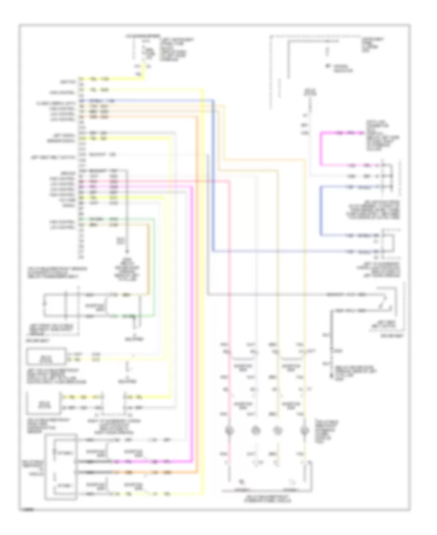
Manual A/C Wiring Diagram for Chevrolet Impala LS 2001
List of elements for Manual A/C Wiring Diagram for Chevrolet Impala LS 2001:
- (dash harn, 6 cm from hvac module breakout)
- (dash harn, 8 cm from ignition sw breakout) s229
- (forward lamp harn, near left headlamp)
- (forward lamp harn, near right headlamp)
- (fuel inj harn, near breakout to map sensor)
- (in underhood junction block (top))
- (left side of hvac module) left air temperature actuator
- (under center of dash)
- (under left side of dash) splice pck sp205
- +5v reference
- 3.4l
- 3.8l
- A/c blo fuse 20a
- A/c blo fuse 25a
- A/c cmpr relay
- A/c compressor clutch & diode
- A/c cruise fuse 10a
- A/c press signal
- A/c refrigerent pressure sensor (left side of engine compt, on liquid line)
- A/c request
- A/c request sig
- A/c rly fuse 10a
- B10
- Battery
- Blower motor
- Blower motor relay
- Blower motor resistor assembly
- Body control module (behind left side of dash)
- C1 f6
- C10
- Comp control
- Coolant fan (left)
- Coolant fan (right)
- D4 c1
- Data link connector (under dash, right side of steering column)
- Defogger on
- Defogger system
- Dic/ rke fuse 10a
- Drvr temp ctrl
- E11
- Ect ground
- Ect signal
- Engine controls (map sensor)
- Engine coolant temperature sensor (left rear of engine)
- F11
- F5 c1
- Fan cont 1 fuse 25a
- Fan cont 1 relay
- Fan cont 2 & 3 fuse 25a
- Fan cont 2 relay
- Fan cont 3 relay
- Fan off input
- G108 (top left front of radiator support)
- G112 (left side of engine, on transaxle stud)
- G205 (right side of steering column)
- G206
- G206 (under center of dash)
- Gnd
- Ground
- High speed
- Hot at all times
- Hot in run
- Hvac control module
- I/p junction block (left) (behind left end of dash)
- I/p junction block (right) (behind right end of dash)
- Ign
- Ignition
- Interior lights
- Interior lights system
- Lamp dim sig
- Low reference
- Low speed
- Nca
- Nca nca
- Off
- Pass temp ctrl
- Pnk
- Pos
- Powertrain control module (left front side of engine compt, in air cleaner assembly)
- Right air temperature actuator (right side of hvac module)
- S121
- S132
- S148
- S158
- S175
- S179
- S216
- Serial data
- Tan
- Underhood junction block (bottom) (froward of right front strut tower)
- Underhood junction block (bottom) (right side of engine compt, forward of strut tower)
- Underhood junction block (top) (froward of right front strut tower)
ANTI-LOCK BRAKES
Anti-lock Brake Wiring Diagrams for Chevrolet Impala LS 2001
List of elements for Anti-lock Brake Wiring Diagrams for Chevrolet Impala LS 2001:
- (below driver door opening)
- (below left side of dash)
- A10
- A11
- A12
- Abs warning ind
- Abs/pcm fuse 10a
- B10
- B11
- Battery
- Body control module (bcm) (behind left side of dash)
- Brake fluid level switch (in master cylinder reservoir)
- Brake ind
- Brake pressure modulator valve
- Brk sw fuse 15a
- C10
- C11
- Data link connector (dlc) (below left side of dash, right of steering column)
- Delivered torque
- Desired torque
- E12
- Electronic brake control module (ebcm) (in left rear of engine compartment)
- G113 (on top of left front framerail)
- G202
- G202 (below left side of dash)
- G309
- Ground
- Hot at all times
- Hot in on or start
- Ignition
- Impala
- Instrument cluster
- Interior lights system
- Left front wheel spd (hi)
- Left front wheel spd (lo)
- Left front wheel speed sensor
- Left i/p accessory wiring junction block (end of dash, in left door opening)
- Left rear wheel spd (hi)
- Left rear wheel spd (lo)
- Left rear wheel speed sensor
- Low trac ind
- Monte carlo
- Nca
- Pnk
- Powertrain control module (pcm) (in air cleaner box)
- Pump motor
- Red
- Right front wheel spd (hi)
- Right front wheel spd (lo)
- Right front wheel speed sensor
- Right i/p accessory wiring junction block (end of dash, in right door opening)
- Right rear wheel spd (hi)
- Right rear wheel spd (lo)
- Right rear wheel speed sensor
- S169
- S190
- S236
- S253
- S322
- S338
- Serial data signal
- Splice pack sp205 (taped to harn, next to left i/p accessory wiring junction block)
- Stop lamp sw out
- Stoplamp switch (on brake pedal support)
- Tan
- Trac off ind
- Traction control switch
- Vent tube
ANTI-THEFT
Anti-theft Wiring Diagram for Chevrolet Impala LS 2001
List of elements for Anti-theft Wiring Diagram for Chevrolet Impala LS 2001:
- 470 ohms
- A10
- A11
- A12
- Accy sig in
- Ajar switch
- B11
- B12
- Backup lps rly ctrl
- Bcm b+
- Bcm fuse 10a
- Body control module (behind left side of dash)
- C420
- Class 2 data line
- Class 2 serial data
- Clstr/bcm fuse 10a
- D12
- Data
- Data link connector (below left side of dash, right of steering column)
- Dk lk fuse 20a
- Door ajar in
- Door locks b+
- Driver door ajar in
- E12
- Exterior lights system
- G202 (on left side of brake pedal bracket)
- G202 (on right side of brake pedal bracket)
- G305 (at base of right "b" pillar)
- Gnd
- Headlamps rly ctrl
- Headlights system
- Horn relay ctrl
- Horns system
- Hot at all times
- Hot in accy or run
- Hot in accy, run or start
- Hot in run or start
- Ign 0 sig in
- Ign 1 sig in
- Ignition lock cylinder
- Instrument cluster
- Left door lock cylinder switch
- Left door lock switch
- Left front side door lock
- Left i/p accessory wiring junction block
- Left i/p junction block
- Left rear side door lock
- Lh htd st/bcm fuse 15a
- Load b+
- Lock
- Lock/unlock in
- Passlock b+
- Passlock data in
- Passlock gnd
- Passlock sensor (part of ignition switch)
- Pcm/bcm clstr fuse 10a
- Pnk
- Power distribution system
- Powertrain control module (in air cleaner box)
- Raf link
- Rear compart- ment lid ajar switch
- Rear compartment occupant sensor
- Remote control door lock receiver (upper center of dash)
- Rfa link
- Right door lock cylinder switch
- Right door lock switch
- Right front side door lock
- Right i/p accessory wiring junction block
- Right i/p junction block
- Right rear side door lock
- S236
- S253
- S322
- S420
- S900
- Security indicator
- Splice pack sp205 (next to left accessory wiring junction block)
- Stop fuse 10a
- Trunk ajar sw
- Unlock
- Unlock in
- W/entrapment protection
- W/o entrapment protection
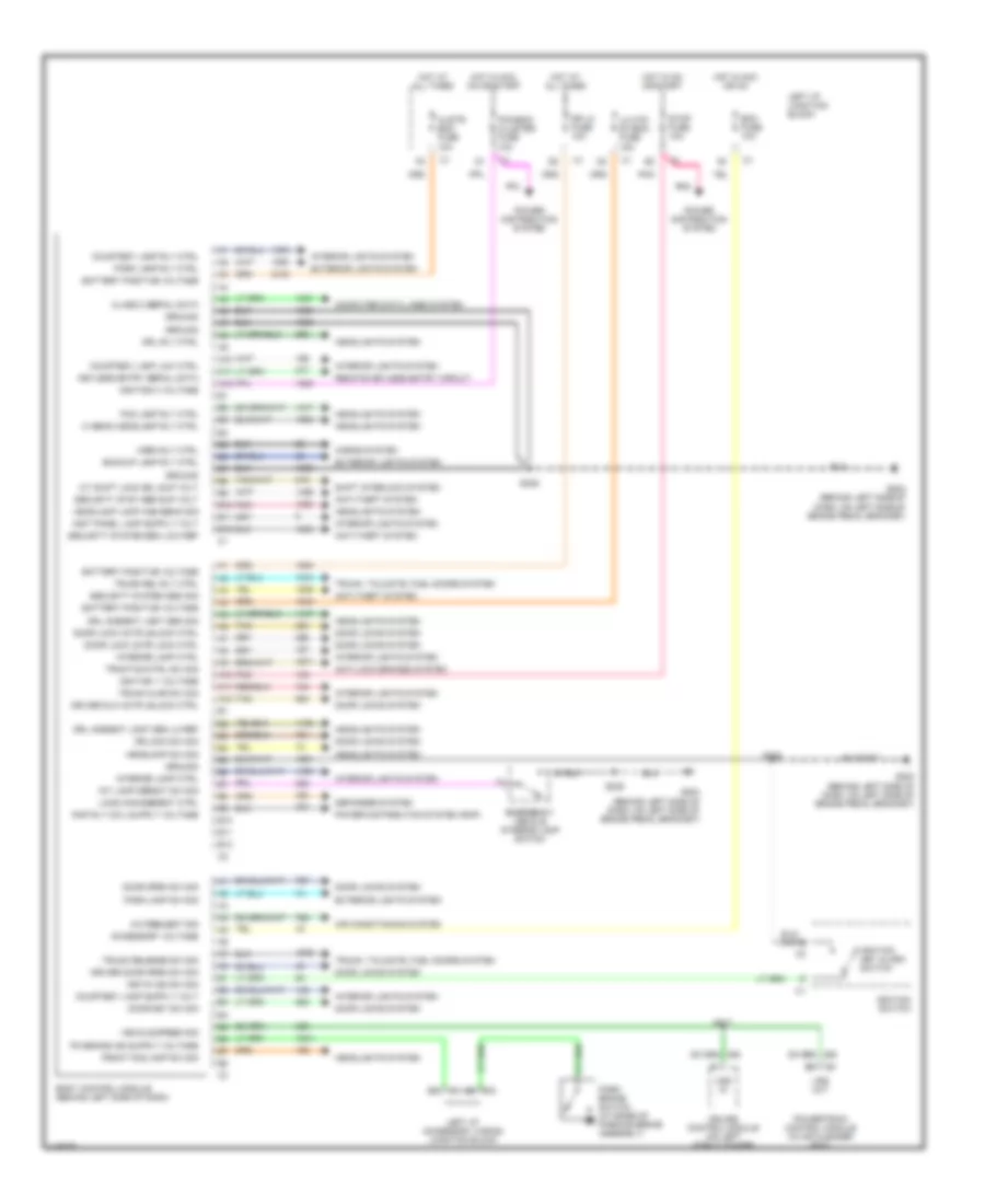
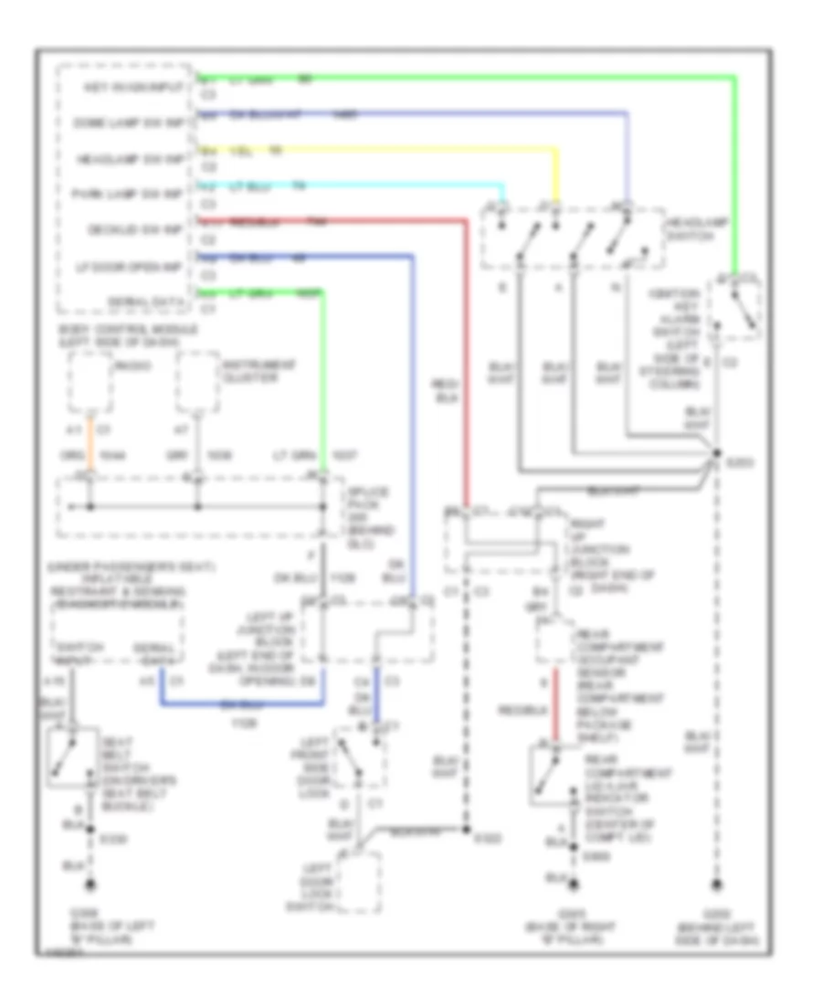
BODY COMPUTER
Body Computer Wiring Diagrams for Chevrolet Impala LS 2001
List of elements for Body Computer Wiring Diagrams for Chevrolet Impala LS 2001:
- A/c request sig
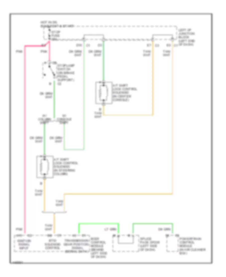
- A/t shift lock sol sup volt
- A10
- A11
- A12
- Accessory voltage
- Air conditioning system
- Anti-lock brakes system
- Anti-theft system
- B10
- B11
- B12
- Backup lamp rly ctrl
- Battery positive voltage
- Bcm fuse 10a
- Body control module (behind left side of dash)
- Class 2 serial data
- Clstr/ bcm fuse 10a
- Computer data lines system
- Courtesy lamp low ctrl
- Courtesy lamp rly ctrl
- Cruise control module (on left strut tower)
- Defogger system
- Door key sw sig
- Door lock actr lock ctrl
- Door lock actr unlock ctrl
- Door locks system
- Door opem sw sig
- Dr lk fuse 10a
- Dr lock sw sig
- Driver dlk actr unlock ctrl
- Driver door open sw sig
- Drl ambient light sen lo ref
- Drl ambient light sen sig
- Drl rly ctrl
- Emergency vehicle interior lamp switch
- Exterior lights system
- Fog lamp rly ctrl
- Front fog lamp sw sig
- G202 (behind left side of dash, on left side of brake pedal bracket)
- Ground
- Headlamp lamp high beam sig
- Headlamp sw sig
- Headlights system
- Hi beam headlamp rly ctrl
- Horn rly ctrl
- Horns system
- Hot at all times
- Hot in acc or on
- Hot in acc, on or start
- Hot in on or start
- Ignition 0 voltage
- Ignition 1 voltage
- Ignition key alarm switch
- Ignition switch
- Int lamp defeat sw sig
- Interior lamp ctrl
- Interior lights system
- Key-in ign sw sig
- Keyless entry serial data
- Left i/p junction block
- Left i/p accessory wiring junction block
- Lh htd st/bcm fuse 15a
- Load management ctrl
- Park brake switch (at base of parking brake assembly)
- Park lamp rly ctrl
- Park lamp sw sig
- Pcm/bcm cluster fuse 10a
- Pnk
- Power distribution system
- Power distribution system (rap)
- Powertrain control module (in air cleaner box)
- Remote keyless entry circuit
- S217
- S236
- S253
- Security syst sen sup volt
- Security system sen low ref
- Security system sen sig
- Shift interlock system
- Stop fuse 10a
- Tan
- Traction ctrl sw sig
- Trunk ajar sw sig
- Trunk rel rly ctrl
- Trunk release sw sig
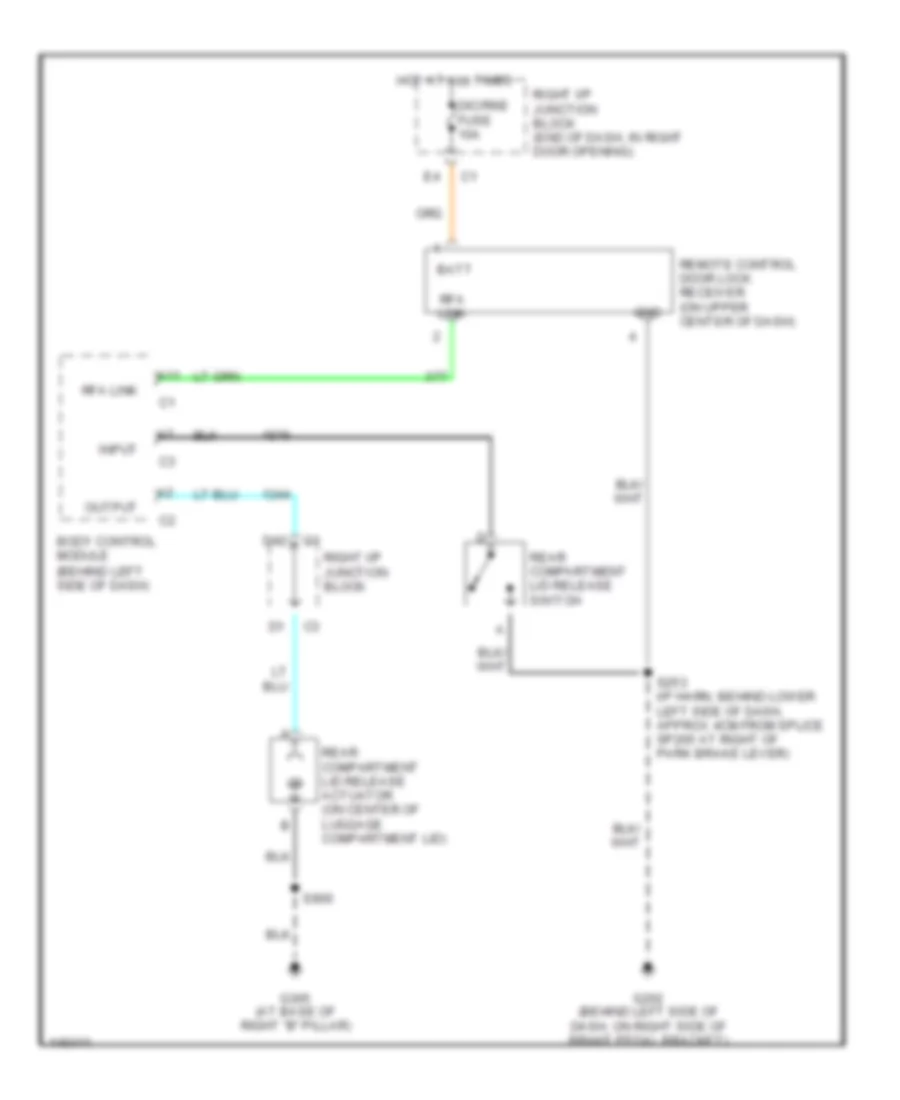
- Trunk, tailgate, fuel doors system
- Vehicle speed sig
- Vss in
- Vss out
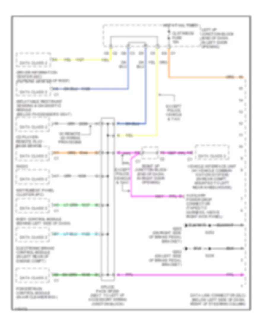
COMPUTER DATA LINES
Computer Data Lines for Chevrolet Impala LS 2001
List of elements for Computer Data Lines for Chevrolet Impala LS 2001:
- Auxiliary power drop connector (taped to harness, above right kick panel)
- Body control module (behind left side of dash)
- C1 e8
- C2 c8
- C3 d8
- Cd player- remote play- back device
- Clstr/bcm fuse 10a
- Data class 2
- Data link connector (dlc) (below left side of dash, right of steering column)
- Driver information center (dic) (in front center of roof)
- Electronic brake control module (in left rear of engine compt)
- Except police vehicle & taxi
- G202 (on left side of brake pedal bracket)
- G202 (on right side of brake pedal bracket)
- Hot at all times
- Inflatable restraint sensing & diagnostic module (below passenger's seat)
- Instrument panel cluster (ipc)
- Left i/p junction block (end of dash, in left door opening)
- Powertrain control module (in air cleaner box)
- Radio
- Right i/p junction block (end of dash, in right door opening)
- S236
- S253
- Splice pack sp205 (next to left i/p accessory wiring juncton block)
- Vehicle interface unit (w/ vehicle commun- ication system) (in rear compt, mounted to left rear wheelhouse)
- W/ remote cd wiring provisions
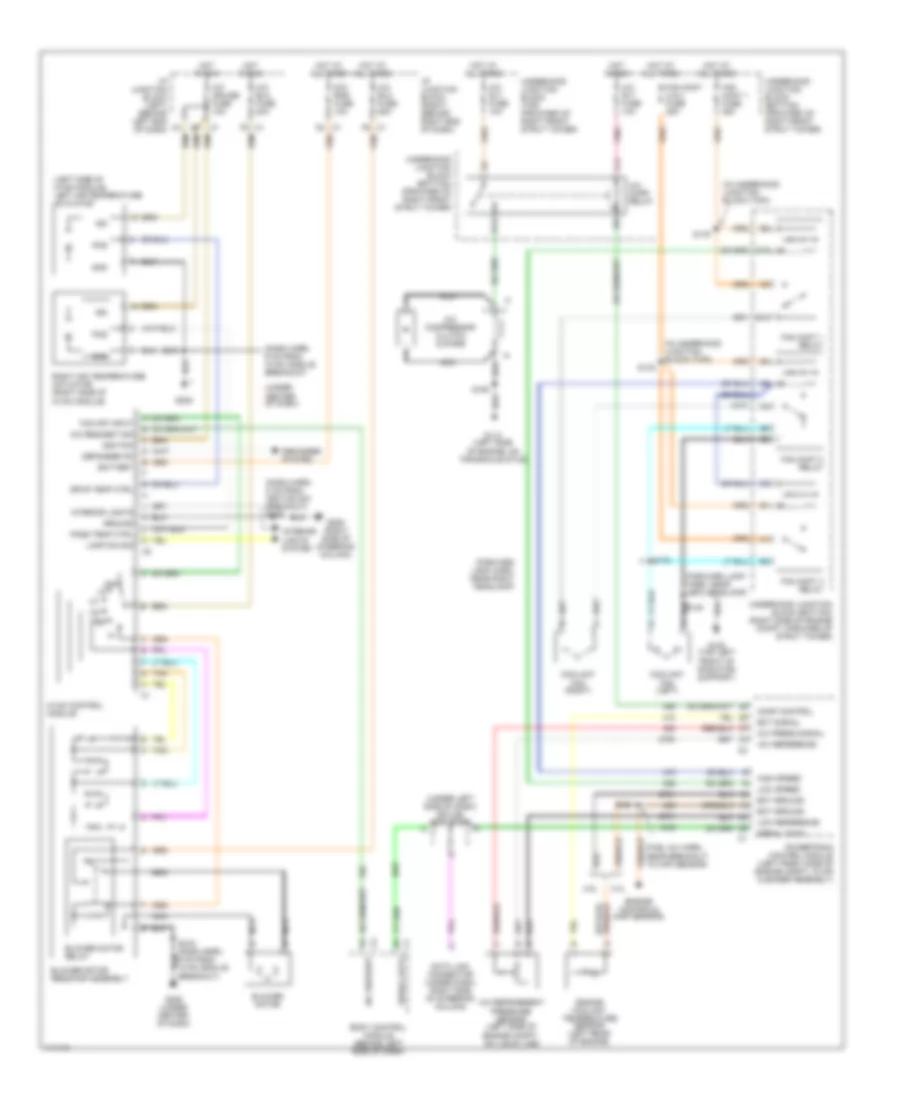
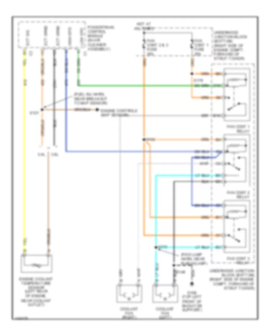
COOLING FAN
Cooling Fan Wiring Diagram for Chevrolet Impala LS 2001
List of elements for Cooling Fan Wiring Diagram for Chevrolet Impala LS 2001:
- (fuel inj harn, near breakout to map sensor)
- (fwd lamp harn, near r headlamp)
- 3.4l
- 3.8l
- B10
- C10
- Coolant fan (left)
- Coolant fan (right)
- Ect sig
- Engine controls (map sensor)
- Engine coolant temperature sensor (left rear of engine, near coolant outlet)
- Fan cont 1 fuse 25a
- Fan cont 1 relay
- Fan cont 2 & 3 fuse 25a
- Fan cont 2 relay
- Fan cont 3 relay
- G108 (top left front of radiator support)
- High spd
- Hot at all times
- Low spd
- Powertrain control module (in air cleaner assembly)
- S121
- S132
- S148
- S175
- S179
- Underhood junction block (bottom) (right side of engine compt, forward of strut tower)
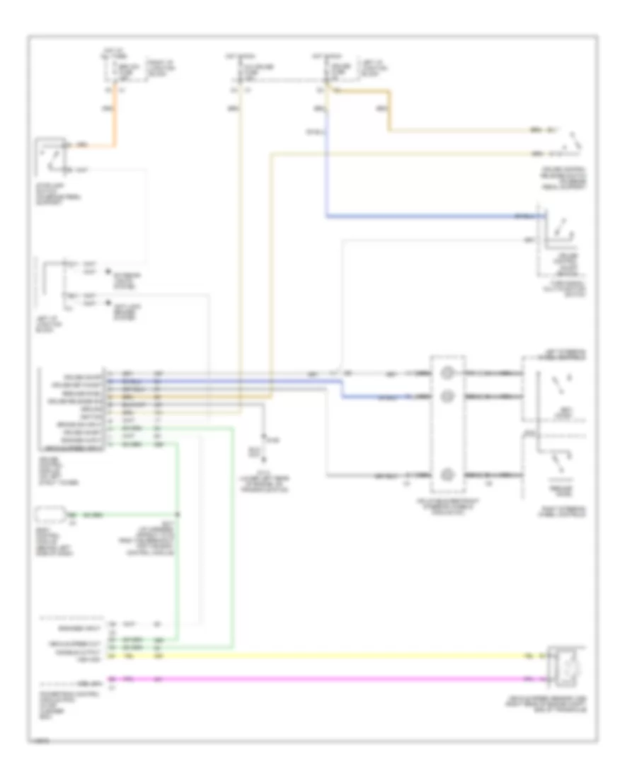
CRUISE CONTROL
Cruise Control Wiring Diagram for Chevrolet Impala LS 2001
List of elements for Cruise Control Wiring Diagram for Chevrolet Impala LS 2001:
- A/c cruise fuse 10a
- All times
- Anti-lock brakes system
- B11
- Body control module (behind left side of dash)
- Brake sig input
- Brk sw fuse 15a
- C11
- Cruise control module (on left strut tower)
- Cruise control on/off switch
- Cruise control release switch (on brake pedal support)
- Cruise fuse 2a
- Cruise inhibit
- Cruise on/off
- Cruise release sig
- Cruise set/coast
- Disable output
- Engage ouput
- Engaged input
- Exterior lights system
- G114 (lower left rear of engine, on transaxle stud)
- Ground
- Hot at
- Hot in run
- Ignition
- Inflatable restraint steering wheels module coil
- Left i/p junction block
- Left steering wheel controls
- Nca
- Powertrain control module (pcm) (in air cleaner box)
- Resume/ accel
- Resume/accel
- Right i/p junction block
- Right steering wheel controls
- S106
- S217 (i/p harness, approx 7.5 cm from the breakout for the body control module)
- Set/ coast
- Stoplamp switch (on brake pedal support)
- Turn signal/ multi-function switch
- Vehicle speed input
- Vehicle speed out
- Vehicle speed sensor (vss) (right rear of engine compt, end of transaxle)
- Vss high
- Vss low
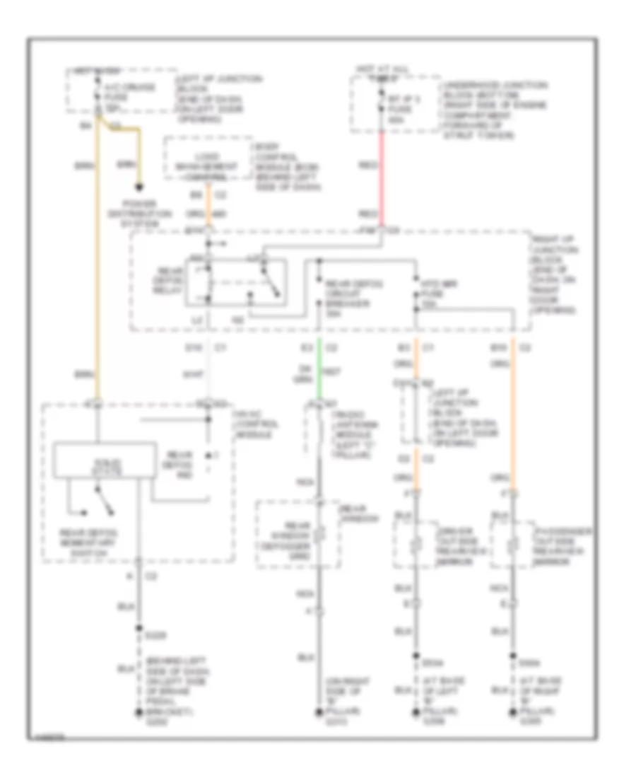
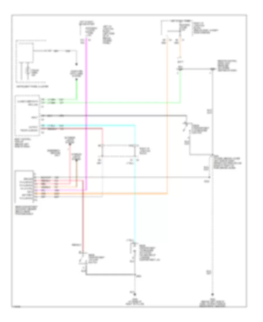
DEFOGGERS
Defogger Wiring Diagram for Chevrolet Impala LS 2001
List of elements for Defogger Wiring Diagram for Chevrolet Impala LS 2001:
- (at base of left "b" pillar) g308
- (at base of right "b" pillar) g305
- (behind left side of dash, on left side of brake pedal bracket) g202
- (on right side of "b" pillar) g313
- A/c cruise fuse 10a
- B10
- Body control module (bcm) (behind left side of dash)
- D10
- D11
- Driver outside rearview mirror
- F10
- Hot at all times
- Hot in on
- Htd mir fuse 10a
- Hvac control module
- Left i/p junction block (end of dash, on left door opening)
- Load management control
- Nca
- Passenger outside rearview mirror
- Power distribution system
- Radio antenna module (left "c" pillar)
- Rear defog circuit breaker 30a
- Rear defog ind
- Rear defog momentary switch
- Rear defog relay
- Rear window
- Rear window defogger grid
- Red
- Right i/p junction block (end of dash, on right door opening)
- Rt ip 3 fuse 60a
- S229
- S504
- S604
- Solid state
- Underhood junction block (bottom) (right side of engine compartment, forward of strut tower)
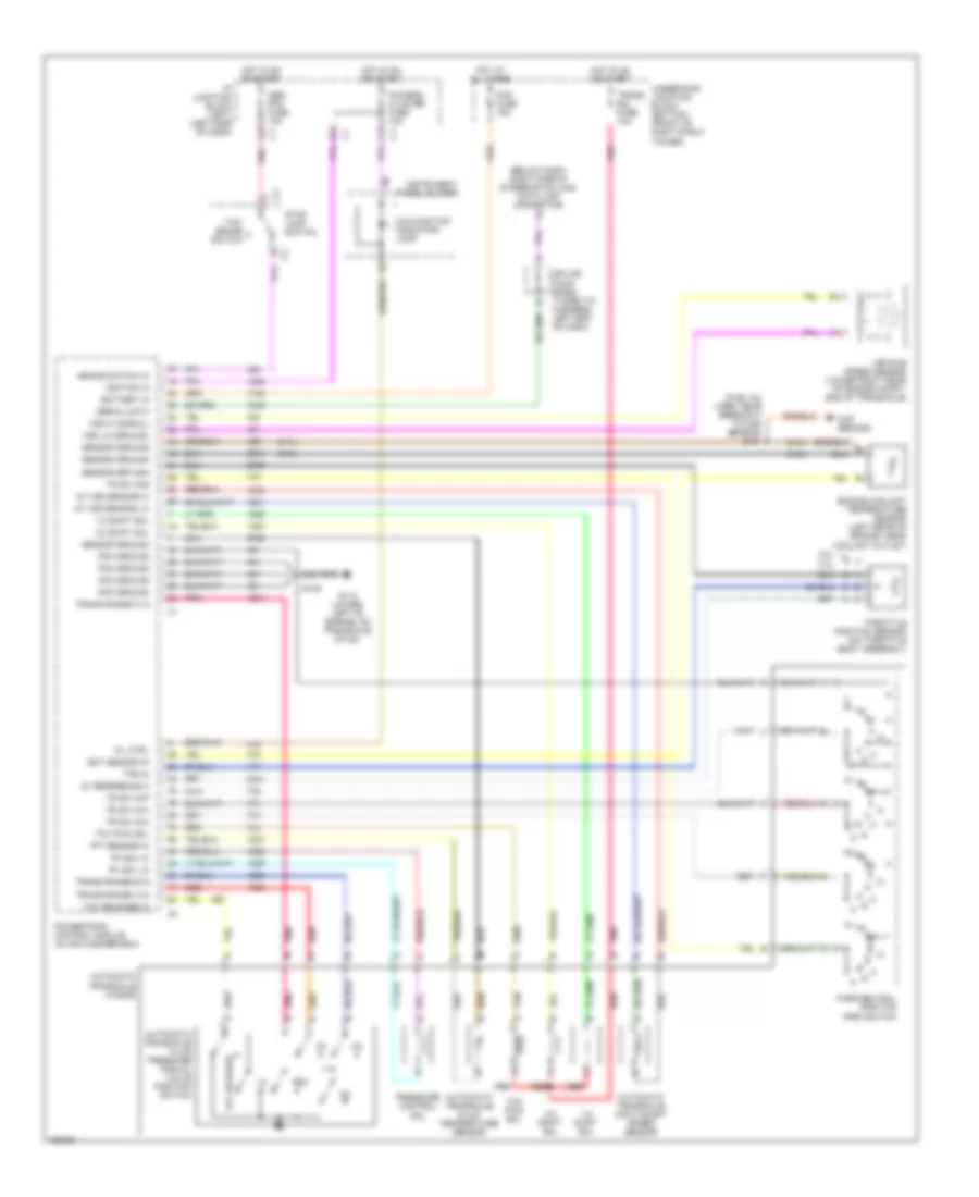
ENGINE PERFORMANCE
3.4L
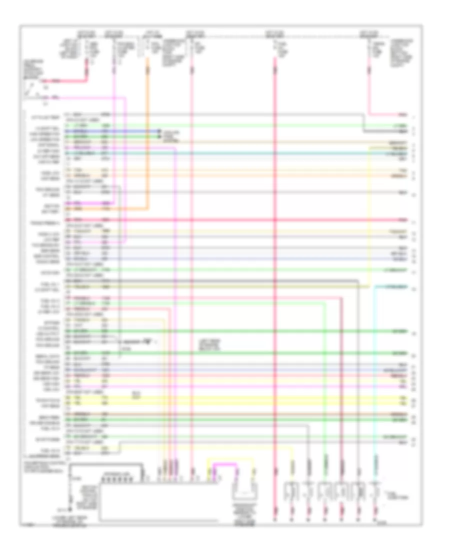
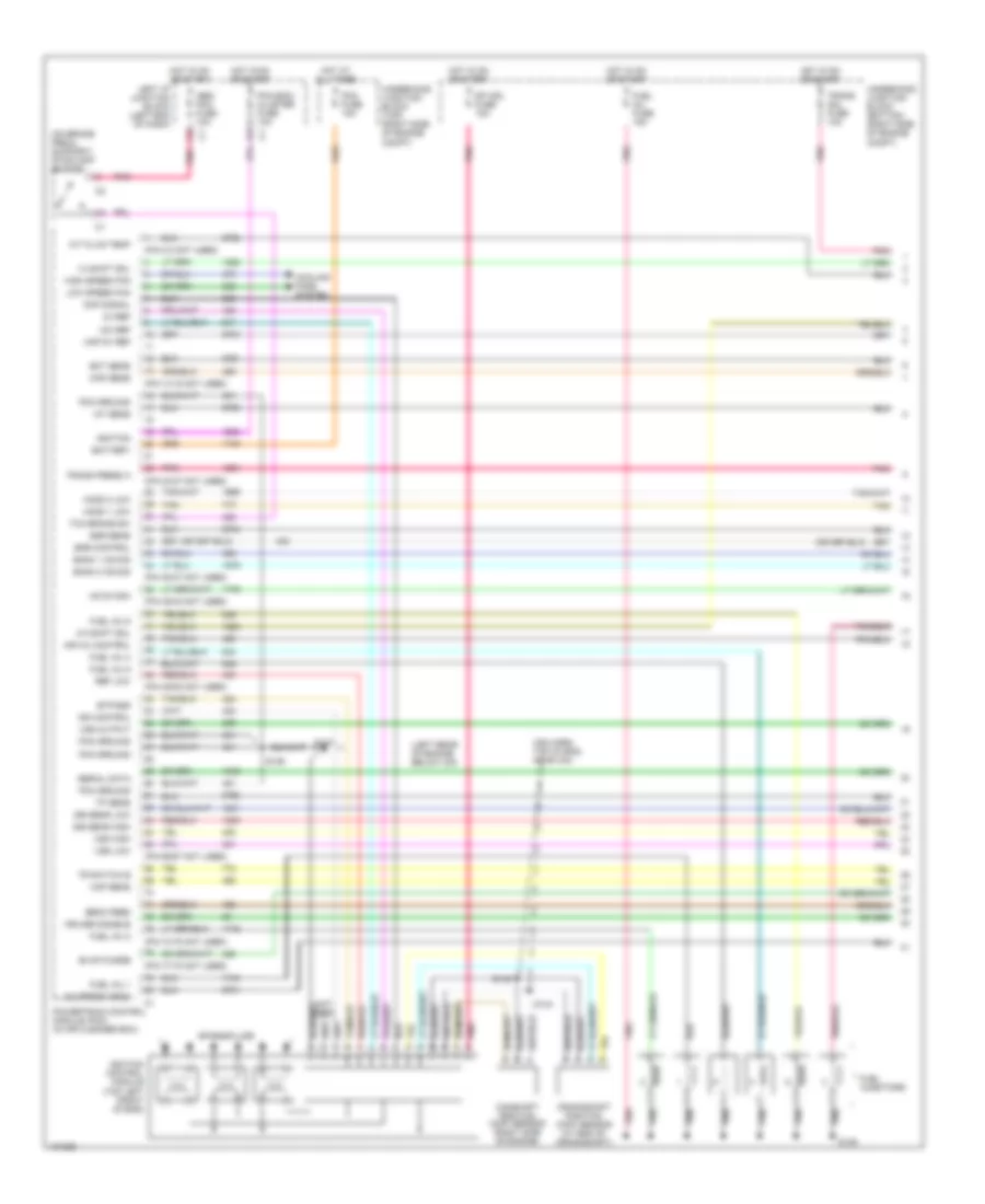
3.4L VIN E, Engine Performance Wiring Diagrams (1 of 4) for Chevrolet Impala LS 2001
List of elements for 3.4L VIN E, Engine Performance Wiring Diagrams (1 of 4) for Chevrolet Impala LS 2001:
- (left rear of engine, below icm)
- (lower left rear of engine, on transaxle stud)
- (on brake pedal support) stoplamp switch
- (pin 14-15 not used)
- (pin 2-3 not used)
- (pin 23-27 not used)
- (pin 34-37 not used)
- (pin 39-42 not used)
- (pin 49-52 not used)
- (pin 66-67 not used)
- (pin 74-75 not used)
- (pin 77-78 not used)
- 1-2 shift sol
- 2-3 shift sol
- 24x ckp sens
- 3x ref high
- 3x ref low
- A/c press sens
- A/t fluid temp
- Abs/ pcm fuse 10a
- Battery
- Bypass
- Cmp signal
- Cooling fans system
- Crankshaft position sensor (7x) (lower right side of engine)
- Cruise disable
- Dfi fuse 15a
- Ebcm feed
- Egr control
- Egr sens
- Evap purge
- Fuel inj 1
- Fuel inj 2
- Fuel inj 3
- Fuel inj 5
- Fuel inj 6
- Fuel inj fuse 15a
- Fuel injectors
- G114
- High speed fan
- Ho2s 2 low
- Ho2s low
- Hot at all times
- Hot in on or start
- Iac b high
- Iat sens
- Ic control
- Ignition
- Ignition control module (on top right side of engine)
- Iss sens high
- Iss sens low
- Knock sens
- Left i/p junction block (left end of dash)
- Low ref
- Low speed fan
- Maf sens
- Map 5v ref
- Map sens
- Pcm fuse 15a
- Pcm ground
- Pcm,bcm/ cluster fuse 10a
- Pnk
- Pnk b
- Powertrain control module (pcm) (in air cleaner box)
- S106
- S109
- S158
- Serial data
- Spark plugs
- Tan
- Tcc brake sw
- Tp sens
- Tr switch b
- Trans press a
- Trans sol fuse 10a
- Underhood junction block (bottom) (right side of engine compt)
- Underhood junction block (top) (right side of engine compt)
- Vss high
- Vss low
- Vss output
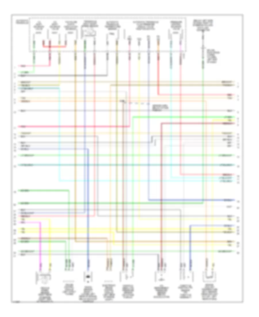
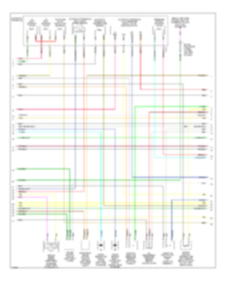
3.4L VIN E, Engine Performance Wiring Diagrams (2 of 4) for Chevrolet Impala LS 2001
List of elements for 3.4L VIN E, Engine Performance Wiring Diagrams (2 of 4) for Chevrolet Impala LS 2001:
- (below left side of dash, right of steering column) data link connector
- (engine harn, below intake plenum)
- 1-2 shift solenoid valve
- 2-3 shift solenoid valve
- A/c refrigerent pressure sensor (below accumulator)
- Automatic transaxle
- Automatic transaxle fluid pressure manual valve position switch
- Automatic transaxle temperature sensor
- C113
- Cruise control module (left strut tower)
- D2, d3
- D2, d4
- E pnk
- Electronic brake control module (left rear of engine compt)
- Engine coolant temperature (ect) sensor (near coolant outlet, left rear of eng)
- Knock sensor (bank 1) (lower left rear of engine, below exhaust manifold)
- Lo, rev
- Manifold absolute pressure sensor (on intake plenum)
- N pnk
- P red
- Pnk
- Pressure control solenoid valve
- Red
- S121
- Splice pack sp205 (taped to harn, left end of dash)
- Tan
- Tcc
- Tcc pulse width modulation solenoid
- Throttle position (tp) sensor (on throttle assembly)
- Transaxle input shaft speed sensor
- Vehicle speed sensor (right rear of engine compt, end of transaxle)
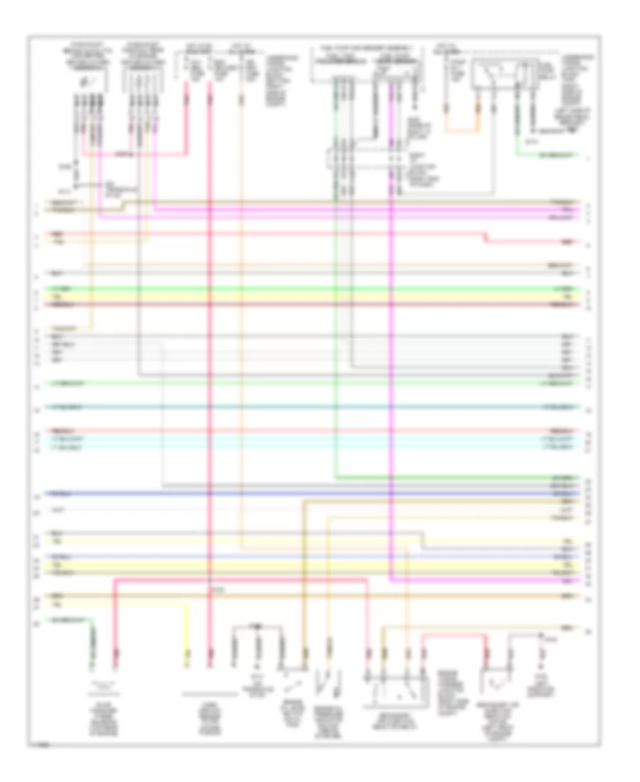
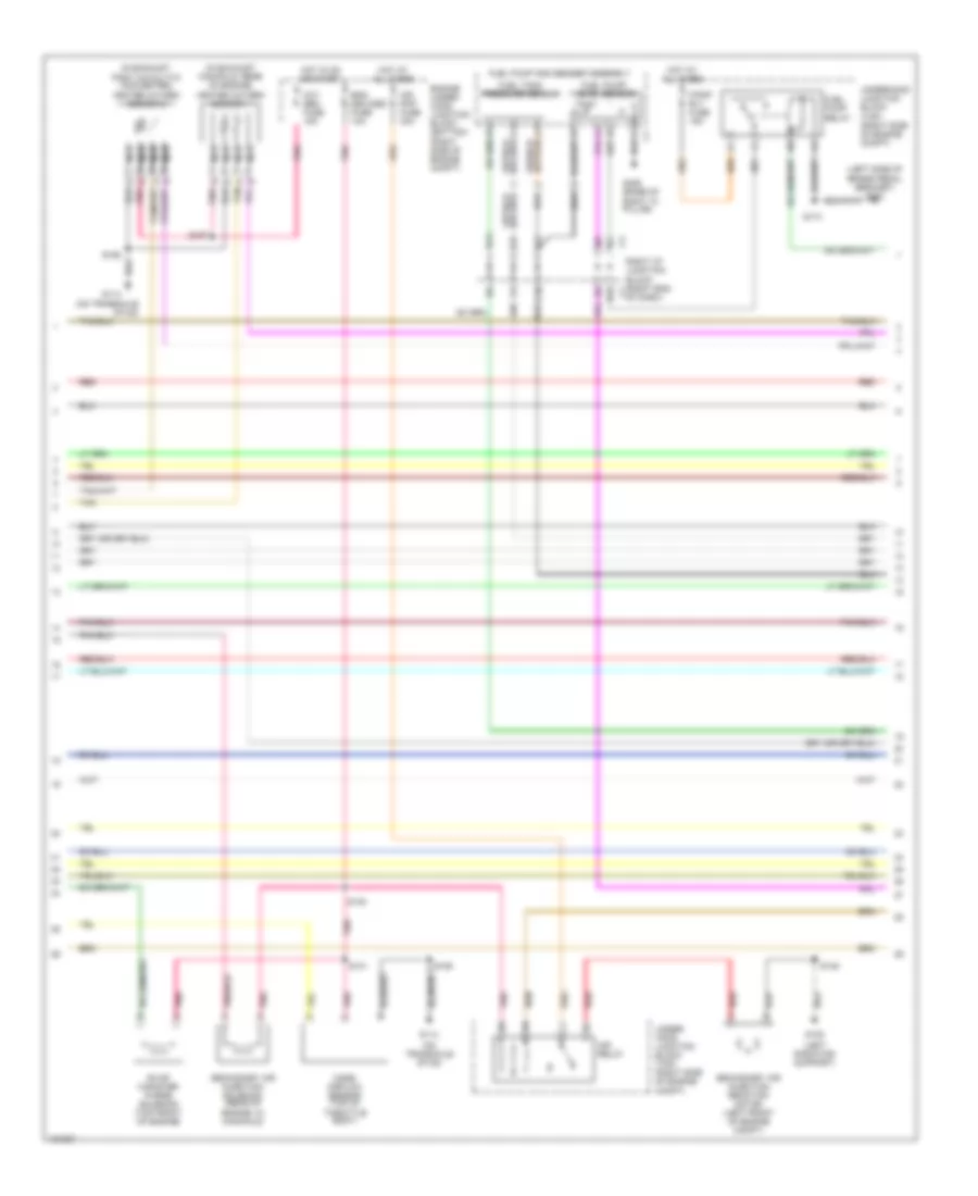
3.4L VIN E, Engine Performance Wiring Diagrams (3 of 4) for Chevrolet Impala LS 2001
List of elements for 3.4L VIN E, Engine Performance Wiring Diagrams (3 of 4) for Chevrolet Impala LS 2001:
- (in exhaust manifold, rear of engine) heated oxygen sensor 1
- (in exhaust, behind catalytic converter) heated oxygen sensor 2
- (left radiator support)
- (left side of brake pedal bracket) g202
- (on transaxle stud)
- (right end of dash)
- A tan
- Air pmp fuse 30a
- B12
- C10
- D pnk
- D11
- Eng devices fuse 10a
- Engine oil level switch (on oil pan)
- Engine oil pressure indicator switch (above starter)
- Engine wiring harness junction block (right side of engine compt)
- Evap canister purge solenoid (top rear of engine)
- F/pmp rly fuse 15a
- Fuel pump and sender assembly
- Fuel pump relay
- Fuel pump/ level sensor
- Fuel tank pressure sensor
- G108
- G114
- G305 (base of
- Hot at all times
- Hot in on or start
- Mass airflow sensor (in air intake plenum)
- Nca
- Oxy sen fuse 15a
- Pnk
- Pnk a
- Pnk c
- Red
- Red a
- Right "a" pillar)
- Right i/p junction block c1
- S106
- S130
- S148
- S157
- S158
- S174
- Secondary air injection reaction motor (left front of engine compt)
- Secondary air injection reaction relay
- Tan
- Underhood wiring junction block (bottom) (right side of engine compt)
- Underhood wiring junction block (top) (right side of engine compt)
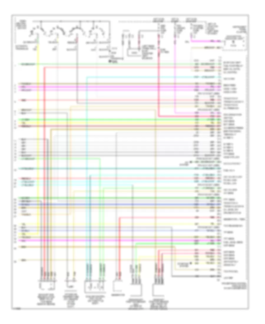
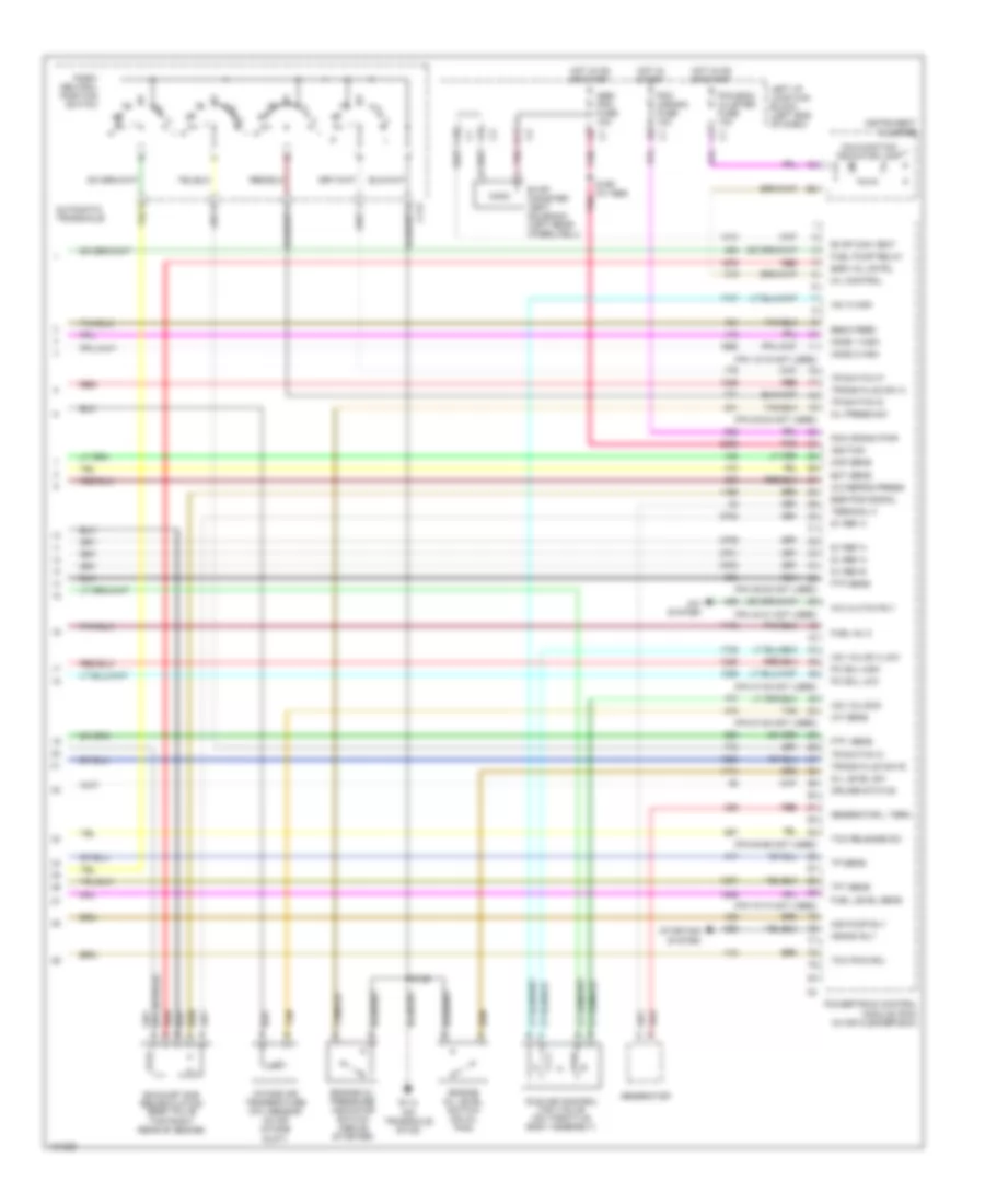
3.4L VIN E, Engine Performance Wiring Diagrams (4 of 4) for Chevrolet Impala LS 2001
List of elements for 3.4L VIN E, Engine Performance Wiring Diagrams (4 of 4) for Chevrolet Impala LS 2001:
- (left rear wheelwell)
- (pin 12-15 not used)
- (pin 20-22 not used)
- (pin 40-41 not used)
- (pin 47-48 not used)
- (pin 51-54 not used)
- (pin 64-65 not used)
- (pins 36,38 not used)
- 5v ref a
- 5v ref b
- A/c clutch rly
- A/c refrig press
- A/c system
- Abs/ pcm fuse 10a
- Air pump rly
- Automatic transaxle
- C10
- C113
- Camshaft position sensor (left front of engine, below intake plenum)
- Ckp sens
- Cmp sens
- Crank rly
- Crankshaft position sensor (24x) (at end of crankshaft)
- Cruise status
- D11
- Ebcm feed
- Ect sens
- Egr pos signal
- Egr val cntrl
- Evap can vent
- Evap canister vent solenoid
- Exhaust gas recirculation (egr) valve (top rear rear of engine)
- Ftp sens
- Ftp sens
- Fuel inj 4
- Fuel level sens
- Fuel pump relay
- G114
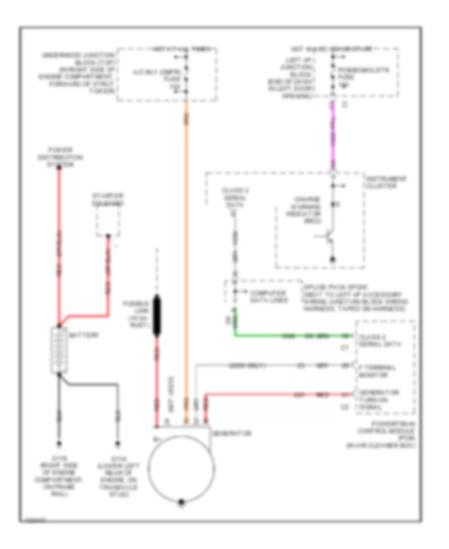
- Generator
- Generator l term
- Ho2s 1 high
- Ho2s 2 high
- Ho2s htr low
- Hot in on or start
- Hot in start
- Iac a high
- Iac valve a low
- Iac valve b
- Iat sens
- Idle air control (iac) valve (on throttle body)
- Ignition
- Instrument panel cluster
- Intake air temperature (iat) sensor (in air intake duct)
- Left i/p junction block (left end of dash)
- Low ref
- Malfunction indicator lamp
- Map sens
- Mil control
- Oil level sw
- Oil press sw
- Park/ neutral position switch
- Pc sol high
- Pc sol low
- Pcm (crank) fuse 10a
- Pcm crank pwr
- Pcm,bcm/ cluster fuse 10a
- Pnk
- Powertrain control module (pcm) (in air cleaner box)
- Red
- Red b
- Red c
- Red e
- S106
- S169 (w/ abs)
- Starting system
- Tan
- Tan b
- Tcc pwm sol
- Tcc release sw
- Terminal f
- Tft sens
- Tp sens
- Tr switch c
- Tr switch d
- Tr switch p
- Trans fluid sw b
- Trans fluid sw c
3.8L
3.8L VIN K, Engine Performance Wiring Diagrams (1 of 4) for Chevrolet Impala LS 2001
List of elements for 3.8L VIN K, Engine Performance Wiring Diagrams (1 of 4) for Chevrolet Impala LS 2001:
- (ign harn, top of eng, near icm)
- (left rear of engine, below icm)
- (on brake pedal support) stoplamp switch
- (pin 14-15 not used)
- (pin 2-3 not used)
- (pin 23-27 not used)
- (pin 35-37 not used)
- (pin 39-42 not used)
- (pin 49-52 not used)
- (pin 66-67 not used)
- (pin 74-75 not used)
- (pin 77-78 not used)
- 1-2 shift sol
- 18x ref
- 2-3 shift sol
- 3x ref
- A/c press sens
- A/t fluid temp
- Abs/ pcm fuse 10a
- Air inj control
- Bank 1 ks sig
- Bank 2 ks sig
- Battery
- Bypass
- Camshaft position (cmp) sensor (right side of engine)
- Cmp signal
- Cooling fans system
- Crankshaft position (ckp) sensor (at end of crankshaft)
- Cruise disable
- Dfi mdl fuse 15a
- Ebcm feed
- Ect sens
- Egr control
- Egr sens
- Evap purge
- Fuel inj 1
- Fuel inj 2
- Fuel inj 4
- Fuel inj 5
- Fuel inj 6
- Fuel inj fuse 15a
- Fuel injectors
- G114
- High speed fan
- Ho2s 1 low
- Ho2s 2 low
- Hot at all times
- Hot in on or start
- Iac b high
- Iat sens
- Ign control
- Ignition
- Ignition control module (top left front of eng)
- Iss sens high
- Iss sens low
- Left i/p junction block (left end of dash)
- Low speed fan
- Maf sens
- Map 5v ref
- Map sens
- Not used
- Pcm fuse 15a
- Pcm ground
- Pcm,bcm/ cluster fuse 10a
- Pnk
- Pnk p
- Powertrain control module (pcm) (in air cleaner box)
- Ref low
- S106
- S109
- S144
- S145
- Serial data
- Spark plugs
- Tan
- Tcc brake sw
- Tp sens
- Tr switch b
- Trans press a
- Trans sol fuse 10a
- Underhood junction block (bottom) (right side of engine compt)
- Underhood junction block (top) (right side of engine compt)
- Vss high
- Vss low
- Vss output
3.8L VIN K, Engine Performance Wiring Diagrams (2 of 4) for Chevrolet Impala LS 2001
List of elements for 3.8L VIN K, Engine Performance Wiring Diagrams (2 of 4) for Chevrolet Impala LS 2001:
- (below left side of dash, right of steering column) data link connector
- 1-2 shift solenoid valve
- 2-3 shift solenoid valve
- A/c refrigerent pressure sensor (below accumulator)
- Automatic transaxle
- Automatic transaxle fluid pressure manual valve position switch
- Automatic transaxle input shaft speed sensor
- Automatic transaxle temperature sensor
- C113
- Cruise control module (left strut tower)
- D2, d3
- D2, d4
- E pnk
- Electronic brake control module (left rear of engine compt)
- Engine coolant temperature (ect) sensor (below coolant outlet, left rear of eng)
- Knock sensor (ks) bank 2 (lower right side of engine)
- Knock sensor bank 1 (lower left side of engine, near starter)
- Lo, rev
- Manifold absolute pressure sensor (on intake plenum)
- N pnk
- P red
- Pnk
- Pressure control solenoid valve
- Red
- Splice pack sp205 (taped to harn, left end of dash)
- Tan
- Tcc
- Tcc pulse width modulation solenoid
- Throttle position (tp) sensor (on throttle assembly)
- Vehicle speed sensor (right rear of engine compt, end of transaxle)
3.8L VIN K, Engine Performance Wiring Diagrams (3 of 4) for Chevrolet Impala LS 2001
List of elements for 3.8L VIN K, Engine Performance Wiring Diagrams (3 of 4) for Chevrolet Impala LS 2001:
- (in exhaust manifold, rear of engine) heated oxygen sensor 1
- (in exhaust, post catalytic converter) heated oxygen sensor 2
- (left radiator support)
- (left side of brake pedal bracket) g202
- (on transaxle stud)
- A tan
- Air pmp fuse 30a
- Air relay
- B12
- C10
- D pnk
- D11
- Eng devices fuse 10a
- Engine under- hood junction block (bottom) (right side of engine compt)
- Evap canister purge solenoid (top front of engine)
- F/pmp rly fuse 15a
- Fuel pump and sender assembly
- Fuel pump relay
- Fuel pump/ level sensor
- Fuel tank pressure sensor
- G108
- G114
- G305 (base of
- Hot at all times
- Hot in on or start
- Mass airflow sensor (top of throttle body)
- Nca
- Of dash)
- Oxy sen fuse 15a
- Pnk
- Pnk a
- Pnk c
- Red
- Red a
- Right "a" pillar)
- Right i/p junction block (right end c1
- S106
- S130
- S131
- S148
- S157
- S158
- S174
- Secondary air injection reaction motor (left front of engine compt)
- Secondary air injection solenoid (rear of engine, in manifold)
- Tan
- Under- hood junction block (top) (right side of engine compt)
- Underhood junction block (top) (right side of engine compt)
3.8L VIN K, Engine Performance Wiring Diagrams (4 of 4) for Chevrolet Impala LS 2001
List of elements for 3.8L VIN K, Engine Performance Wiring Diagrams (4 of 4) for Chevrolet Impala LS 2001:
- (on transaxle stud)
- (pin 12-15 not used)
- (pin 20-22 not used)
- (pin 36-38 not used)
- (pin 40-41 not used)
- (pin 47-48 not used)
- (pin 51-54 not used)
- (pin 64-65 not used)
- (pin 70-74 not used)
- 5v ref a
- 5v ref b
- A/c clutch rly
- A/c refrig press
- A/c system
- Abs/ pcm fuse 10a
- Air pump rly
- Automatic transaxle
- C10
- C113
- Crank rly
- Cruise status
- D11
- Ebcm feed
- Ect sens
- Egr pos signal
- Egr val cntrl
- Engine oil level switch (on oil pan)
- Engine oil pressure indicator switch (above starter)
- Evap can vent
- Evap canister vent solenoid (left rear wheelwell)
- Exhaust gas recirculation (egr) valve (top right rear of engine)
- Ftp sens
- Ftp sens
- Fuel inj 3
- Fuel level sens
- Fuel pump relay
- G114
- Generator
- Generator l term
- Ho2s 1 high
- Ho2s 2 high
- Hot in on or start
- Hot in start
- Iac a high
- Iac valve a low
- Iac valve b
- Iat sens
- Idle air control (iac) valve (on throttle body assembly)
- Ignition
- Instrument cluster
- Intake air temperature (iat) sensor (in air intake duct)
- Left i/p junction block (left end of dash)
- Malfunction indicator lamp
- Map sens
- Mil control
- Oil level sw
- Oil press sw
- Park/ neutral position switch
- Pc sol high
- Pc sol low
- Pcm (crank) fuse 10a
- Pcm crank pwr
- Pcm,bcm/ cluster fuse 10a
- Pnk
- Powertrain control module (pcm) (in air cleaner box)
- Red
- Red b
- Red e
- S106
- S169 (w/ abs)
- Starting system
- Tan
- Tan b
- Tcc pwm sol
- Tcc release sw
- Terminal f
- Tft sens
- Tp sens
- Tr switch c
- Tr switch d
- Tr switch p
- Trans fluid sw b
- Trans fluid sw c
EXTERIOR LIGHTS
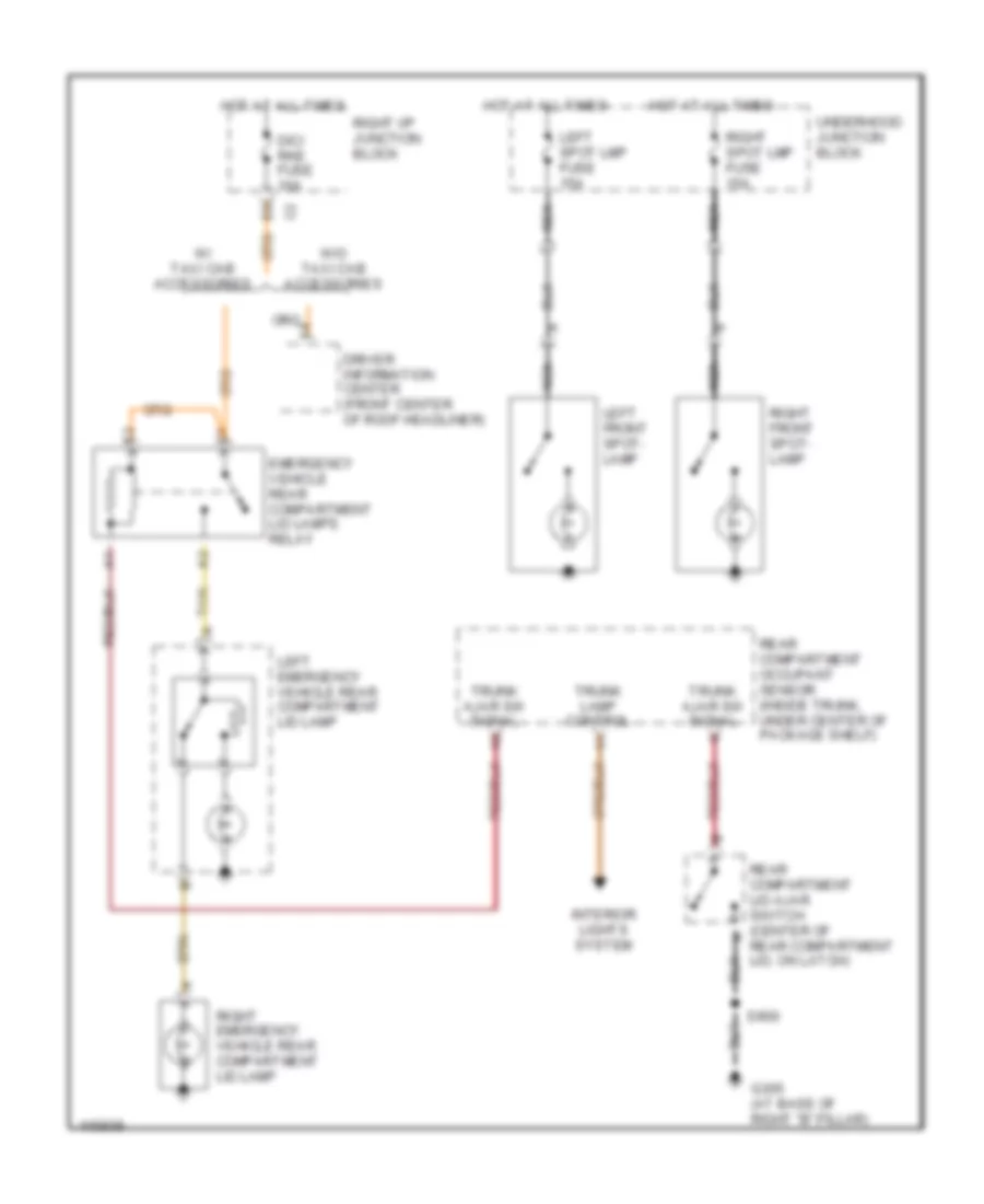
Accessory Lamps Wiring Diagram for Chevrolet Impala LS 2001
List of elements for Accessory Lamps Wiring Diagram for Chevrolet Impala LS 2001:
- Dic/ rke fuse 10a
- Driver information center (front center of roof headliner)
- Emergency vehicle rear compartment lid lamps relay
- G305 (at base of right "b" pillar)
- Hot at all times
- Interior lights system
- Left emergency vehicle rear compartment lid lamp
- Left front spot- lamp
- Left spot lmp fuse 15a
- Nca
- Rear compartment lid ajar switch (center of rear compartment lid, on latch)
- Rear compartment occupant sensor (inside trunk, under center of package shelf)
- Right emergency vehicle rear compartment lid lamp
- Right front spot- lamp
- Right i/p junction block
- Right spot lmp fuse 15a
- S900
- Tan
- Trunk ajar sw signal
- Trunk lamp control
- Underhood junction block
- W/ taxi cab accessories
- W/o taxi cab accessories
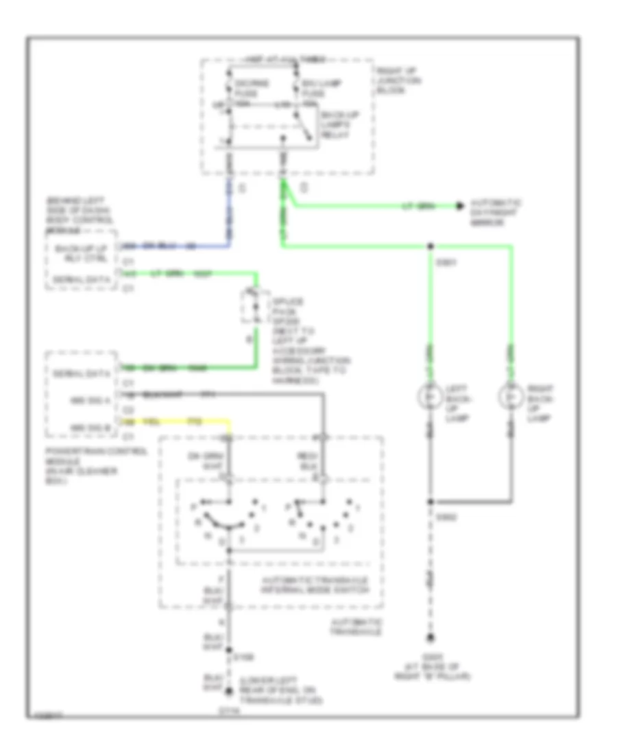
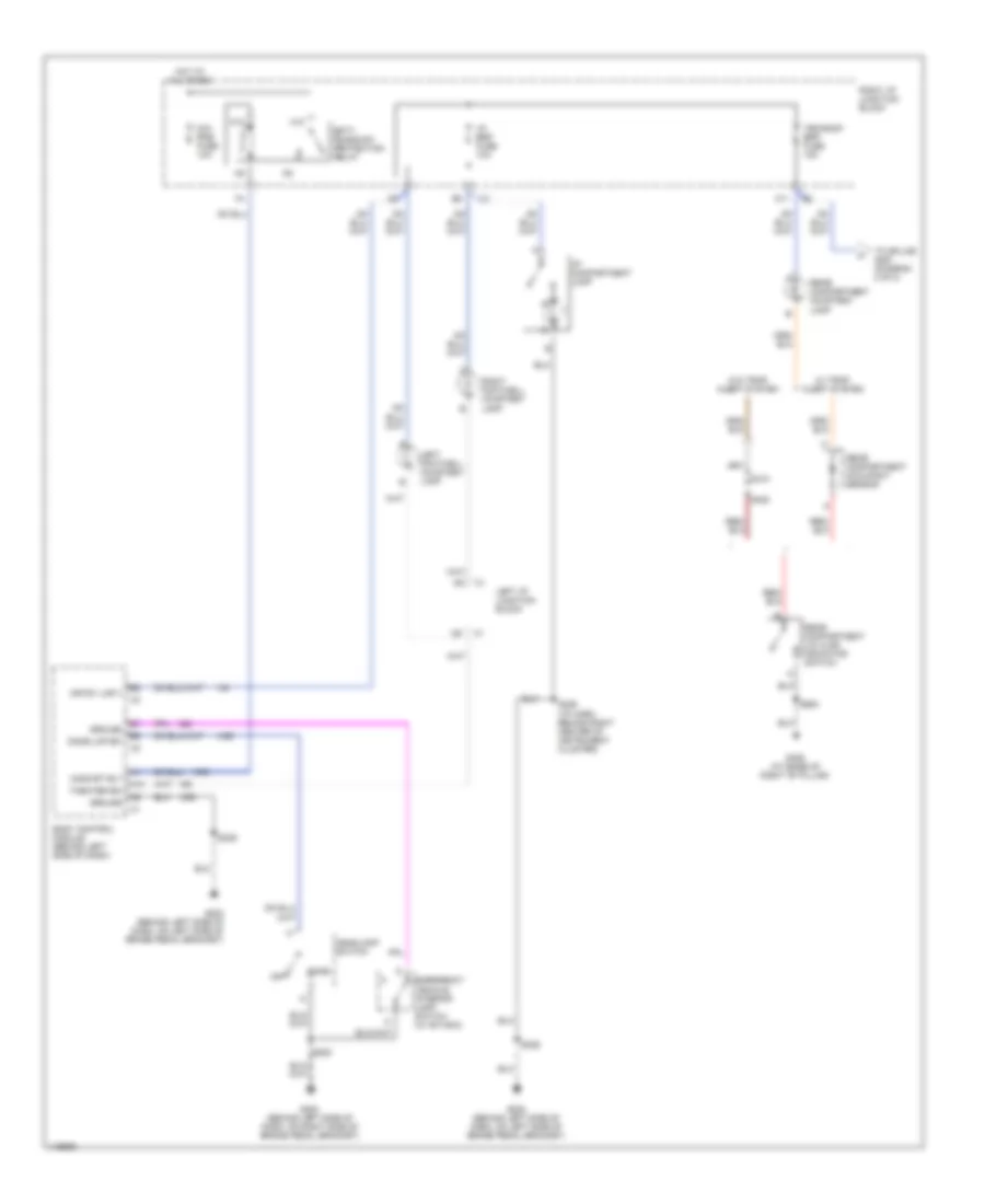
Back-up Lamps Wiring Diagram for Chevrolet Impala LS 2001
List of elements for Back-up Lamps Wiring Diagram for Chevrolet Impala LS 2001:
- (behind left side of dash) body control module
- (lower left rear of eng, on transaxle stud)
- Automatic day/night mirror
- Automatic transaxle
- Automatic transaxle internal mode switch
- B/u lamp fuse 10a
- Back-up lamps relay
- Back-up lp rly ctrl
- D10
- Dic/rke fuse 10a
- G114
- G305 (at base of right "b" pillar)
- Hot at all times
- Ims sig a
- Ims sig b
- L10
- Left back- up lamp
- N10
- Powertrain control module (in air cleaner box)
- Right back- up lamp
- Right i/p junction block
- S108
- S901
- S902
- Serial data
- Splice pack sp205 (next to left i/p accessory wiring junction block, tape to harness)
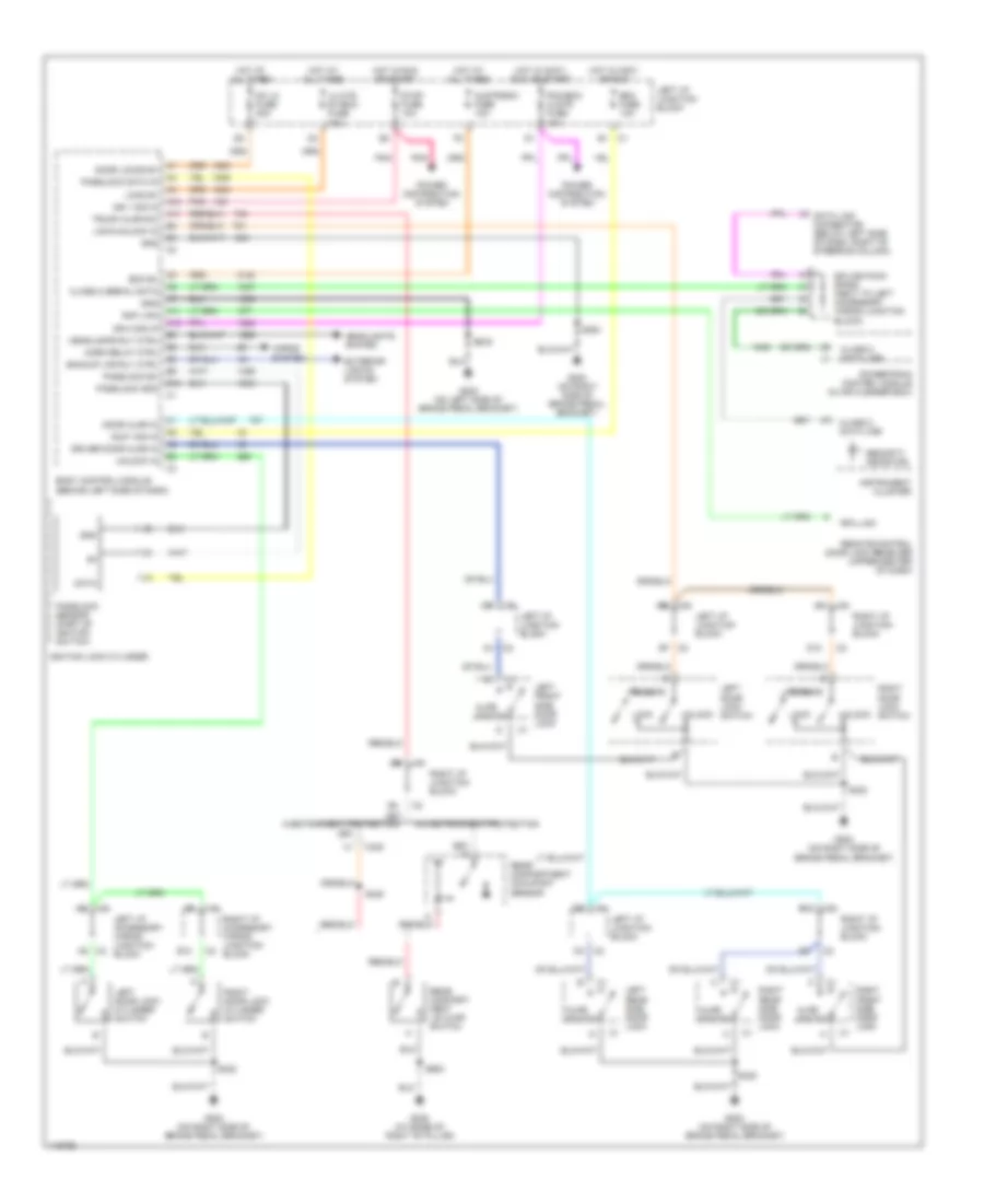
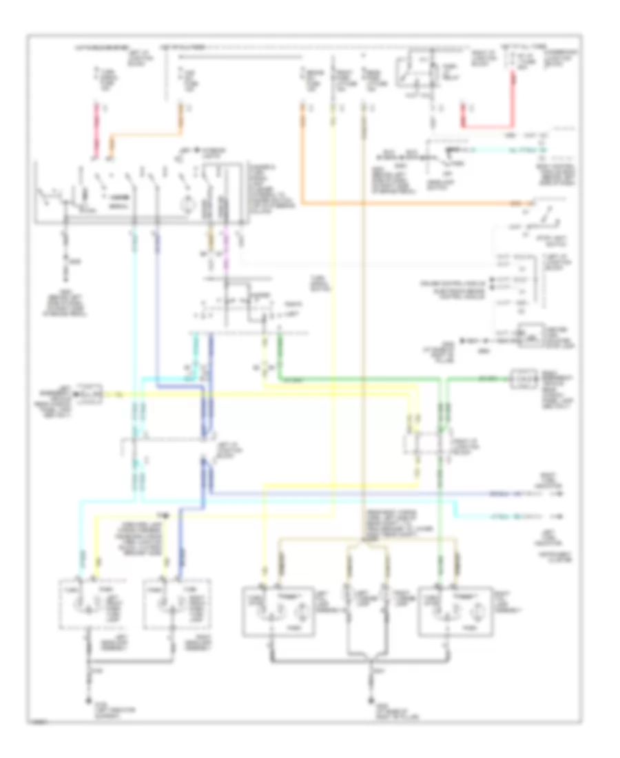
Exterior Lamps Wiring Diagram for Chevrolet Impala LS 2001
List of elements for Exterior Lamps Wiring Diagram for Chevrolet Impala LS 2001:
- (forward lamp wiring harness, inside eng wiring harn junction block, 3 in from bracket side)
- (rear body wiring harn, left side of rear compt, 7 in from grommet at lower right rear compt) s400
- A10
- A11
- B10
- B11
- Body control module (bcm) (behind left side of dash)
- Brake sw fuse 15a
- C11
- Center high mounted stop lamp
- Cluster
- Cruise control module
- E10
- Electronic brake control module
- F12
- Front park lp fuse 15a
- G108 (left radiator support)
- G202 (behind left side of dash, on right side of brake pedal)
- G305 (at base of right "b" pillar)
- H11
- H12
- Haz sw fuse 15a
- Hazard
- Hazard & turn signal lamp flasher (integral to hazard switch, top of steering column)
- Hazard sig sw out
- Head
- Headlamp switch
- Hot at all times
- Hot in run or start
- Instrument
- Interior lights
- K11
- K12
- Led
- Left
- Left emergency vehicle rear window panel lamp (seo only)
- Left front park/ turn lamp
- Left headlamp assembly
- Left i/p junction block
- Left license lamp
- Left tail lamp assembly
- Left turn indicator
- Normal
- Off
- Park
- Park lp relay
- Pnk
- Rear park lp fuse 15a
- Red
- Right
- Right emergency vehicle rear window panel lamp (seo only)
- Right front park/ turn lamp
- Right headlamp assembly
- Right i/p junction block
- Right license lamp
- Right tail lamp assembly
- Right turn indicator
- Rt i/p 1 fuse 60a
- S150
- S176
- S229
- S253
- S401
- S900
- Stop light switch
- Timer
- Turn
- Turn sig sw out
- Turn signal fuse 15a
- Turn signal switch
- Turn/ stop
- Underhood junction block
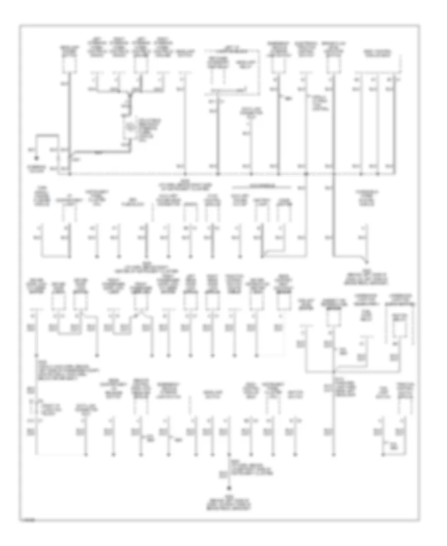
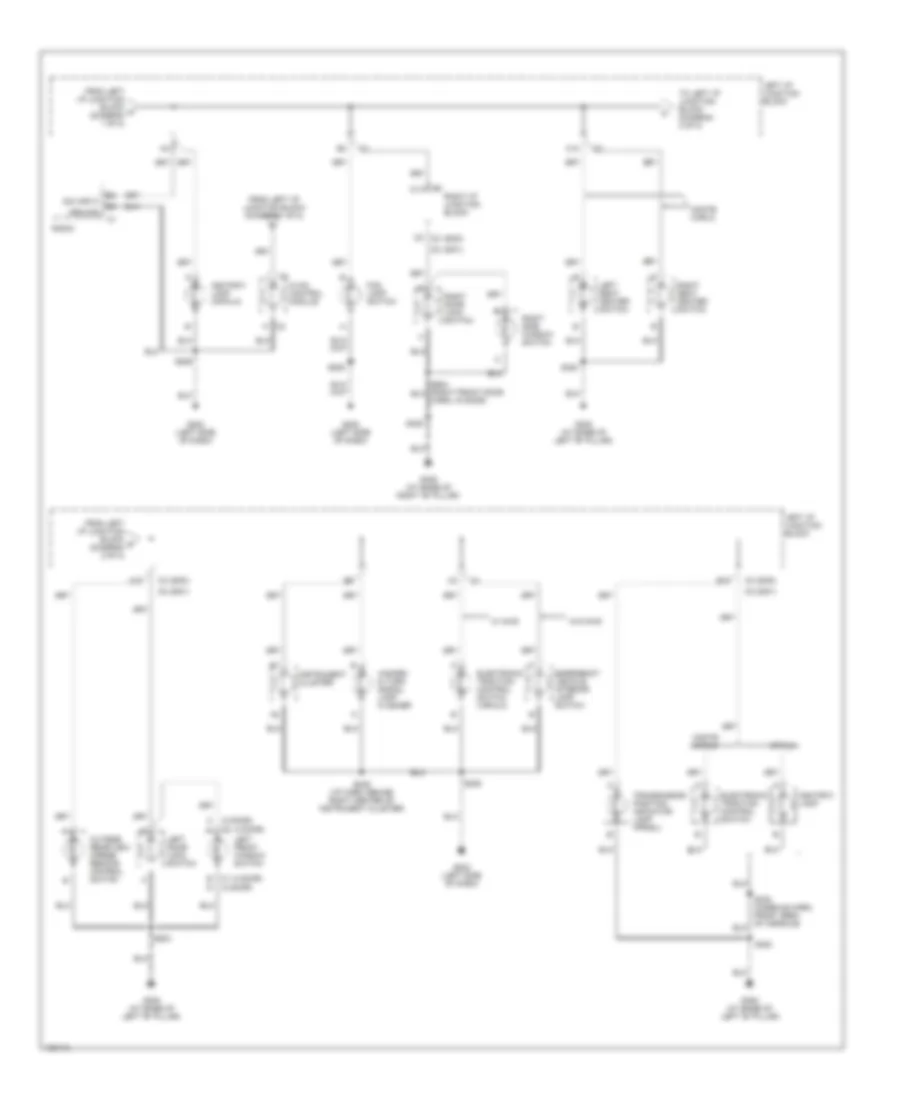
GROUND DISTRIBUTION
Ground Distribution Wiring Diagram (1 of 3) for Chevrolet Impala LS 2001
List of elements for Ground Distribution Wiring Diagram (1 of 3) for Chevrolet Impala LS 2001:
- 3.4 l
- 3.8 l
- A/c compressor
- A12
- Audio amplifier
- Automatic transaxle
- Battery
- Blower motor resistor assembly
- C113
- C122
- California
- Cd player remote playback device
- Cruise control module (ccm)
- Drl relay
- Electronic brake control module (ebcm)
- Engine oil level switch
- Engine oil pressure indicator switch
- Fan cont 2 relay
- G108 (left radiator support)
- G114 (lower left rear of engine, below ignition control module)
- G114 (lower left rear of engine, on transaxle stud)
- G118 (right side of engine compartment, on frame rail)
- G206 (behind center of dash)
- Heated oxygen sensor (ho2s) 1
- Heated oxygen sensor (ho2s) 2
- Horn assembly
- Ignition control module (icm)
- Left air temperature actuator
- Left cooling fan
- Left front fog lamp
- Left headlamp assembly
- Mass air- flow (maf) sensor
- Powertrain control module (pcm)
- Radio
- Right air temperature actuator
- Right front fog lamp
- Right headlamp assembly
- Right i/p junction block
- S106 (l36: engine harn, below left side of radiator) (la1: engine harn, on left side of engine compt, above transaxle)
- S158 (l36: engine harn, left rear side of engine) (la1: engine harn, left front of engine compt)
- S190 (engine harn, lower left front side of engine)
- S216 (i/p harn, behind center of instrument cluster)
- Secondary air injection pump motor
- Special equipment option (seo)
- Underhood junction block (bottom)
- Underhood junction block (top)
- Vehicle interface unit (viu)
- W/ viu
- W/o seo
- W/o viu
- Windshield washer solvent container
- Windshield washer solvent level switch
- Windshield washer solvent pump
Ground Distribution Wiring Diagram (2 of 3) for Chevrolet Impala LS 2001
List of elements for Ground Distribution Wiring Diagram (2 of 3) for Chevrolet Impala LS 2001:
- A11
- Ambient air temperature sensor
- Ashtray lamp
- Auxiliary power drop connector
- Auxiliary power outlet
- Body control module (bcm)
- Brake fluid level indicator switch
- C12
- C201
- Cigar lighter
- Coolant level switch
- Data link connector (dlc)
- Driver door lock
- Driver door lock cylinder switch
- Driver door lock switch
- Driver information center (dic)
- E11
- Electronic traction control switch
- Emergency vehicle interior lamp switch
- Fog lamp switch
- Front passenger door lock
- Front passenger door lock cylinder switch
- Front passenger door lock lock
- Fuel pump relay
- G202 (behind left side of dash, on left side of brake pedal bracket)
- G202 (behind left side of dash, on right side of brake pedal bracket)
- Headlamp dimmer switch
- Headlamp relay
- Headlamp switch
- Hvac control module
- I/p compartment lamp
- Ignition relay
- Ignition switch
- Impala w/trac- tion control
- Inflatable restraint steering wheel module coil
- Instrument panel cluster (ipc)
- Left i/p junction block
- Left rear door lock (impala)
- Left steering wheel controls (cruise)
- Left steering wheel controls (radio)
- N/a seo
- Nca
- Radio
- Rear compart- ment occupant sensor
- Rear compartment lid release switch
- Remote control door lock receiver (rcdlr)
- Retained accessory pwr relay
- Right i/p junction block
- Right rear door lock (impala)
- Right steering wheel controls (cruise)
- Right steering wheel controls (radio)
- S174 (forward lamp harn, near left headlamp)
- S229 (i/p harn, behind right center of instrument cluster)
- S236 (i/p harn, behind right side of instrument cluster)
- S253 (i/p harn, behind lower right side of instrument cluster)
- S322 (impala: main harn, behind left side of passenger compt) (monte carlo: main harn, below driver seat)
- Seo
- Seo fuse block
- Steering column
- Traction control switch (impala)
- Traction control switch (monte carlo)
- Turn signal/ hazard flasher module
- Underhood junction block (bottom)
- Underhood junction block (top)
- W/o console
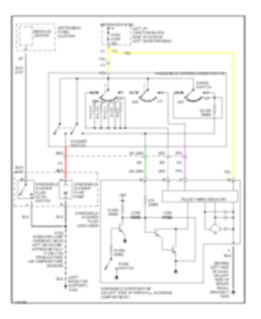
- Windshield wiper system module
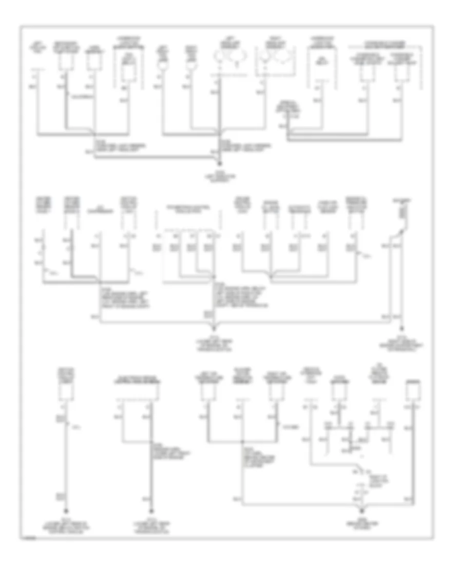
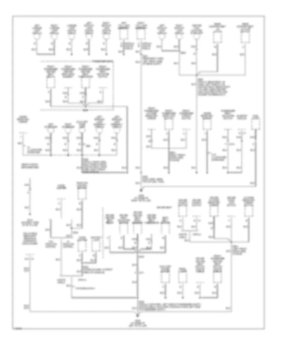
Ground Distribution Wiring Diagram (3 of 3) for Chevrolet Impala LS 2001
List of elements for Ground Distribution Wiring Diagram (3 of 3) for Chevrolet Impala LS 2001:
- A18
- Ashtray lamp
- Auxiliary dome lamp
- Auxiliary power outlet
- C (impala) (monte b
- C311
- C312
- Carlo)
- Center high mounted stoplamp
- Cigar lighter
- Driver door lock switch
- Driver heated seat back element
- Driver heated seat relay
- Driver heated seat switch (monte carlo)
- Driver heated seat thermistor
- Driver outside rearview mirror
- Driver seat
- Driver seat adjuster switch
- Driver window switch
- Front passenger door lock switch
- Front passenger heated seat back element
- Front passenger heated seat relay
- Front passenger heated seat switch (monte carlo)
- Front passenger heated seat thermistor
- Front passenger outside rearview mirror
- Front passenger seat adjuster switch
- Front passenger window switch
- Fuel pump
- G305 (at base of right "b" pillar)
- G308 (at base of left "b" pillar)
- G313 (on right side of "b" pillar)
- Harn, right front side of roof)
- Impala
- Inflatable restraint sensing & diagnostic module (sdm)
- Inside rearview mirror
- Left backup lamp (impala)
- Left backup lamp (monte carlo)
- Left license lamp (impala)
- Left reading lamp assembly (impala)
- Left sunshade
- Left tail lamp assembly
- License lamp (monte carlo)
- Monte carlo
- Nca
- Of rear compt)
- Outside rearview mirror switch
- Passenger seat
- Passenger seat adjuster switch
- Prndl lamp
- Rear compartment lid ajar switch
- Rear compartment lid latch
- Rear window defogger grid
- Right backup lamp (impala)
- Right backup lamp (monte carlo)
- Right license lamp (impala)
- Right sunshade
- Right tail lamp assembly
- S330
- S333
- S338
- S504 (left front door harn, in door)
- S604 (right front door harn, in door)
- S900 (impala: rear deck lid harn, left side of lid) (monte carlo: rear compt lid harn, near center high mounted stoplamp connector breakout)
- S902
- Seat belt switch
- Seo
- Sunroof module
- Traction control switch
- W/ illuminated sunshade
- W/ traction control
- W/console only
- W/o illuminated sunshade
- W/o traction control
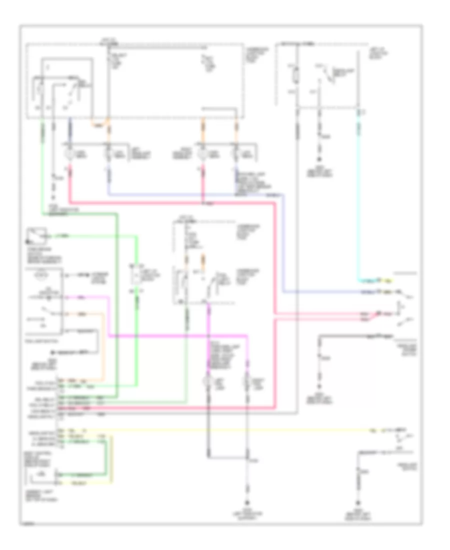
HEADLIGHTS
Headlight Wiring Diagram for Chevrolet Impala LS 2001
List of elements for Headlight Wiring Diagram for Chevrolet Impala LS 2001:
- (foward lamp harn, 4 cm from outside air temp sensor breakout) s173
- A11
- A12
- Al sens ref
- Al sens sig
- Ambient light sensor (on top of dash)
- B10
- Body control module (behind right side of dash)
- C11
- C12
- Drl relay
- Drl/ext lts fuse 15a
- E10 c1
- E11
- Ext lts fuse 10a
- F11
- F12
- Fog lamp switch
- Fog light relay
- Fog lp relay
- Fog lp sw
- Fog rly fuse 10a
- G pnk
- G108 (left radiator support)
- G202 (behind left side of dash)
- Head
- Headlamp dimmer switch
- Headlamp relay
- Headlamp rly
- Headlamp sw
- Headlamp switch
- High beam
- High beam in
- Hot at all times
- Interior lights system
- Left fog lamp
- Left headlamp assembly
- Left i/p junction block
- Low beam
- Off
- On indicator
- Park brake in
- Park brake switch (base of parking brake assembly)
- Pnk
- Right fog lamp
- Right headlamp assembly
- S150
- S236
- S253
- Underhood junction block (top)
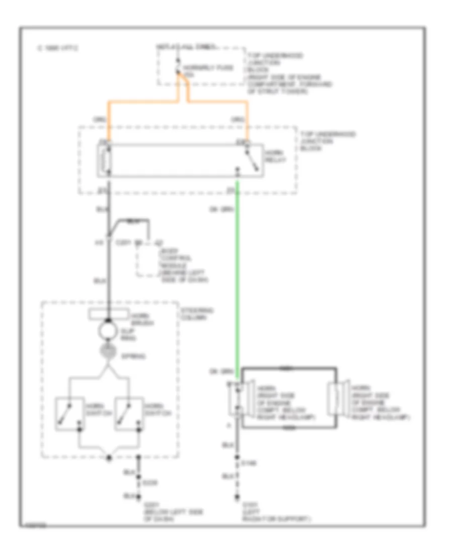
HORN
Horn Wiring Diagram for Chevrolet Impala LS 2001
List of elements for Horn Wiring Diagram for Chevrolet Impala LS 2001:
- 1995 vftc c
- Body control module (behind left side of dash)
- C201
- G101 (left radiator support)
- G201 (below left side of dash)
- Horn (right side of engine compt, below right headlamp)
- Horn brush
- Horn relay
- Horn switch
- Horn/rly fuse 15a
- Hot at all times
- Nca
- S148
- S236
- Slip ring
- Spring
- Steering column
- Top underhood junction block
- Top underhood junction block (right side of engine compartment, forward of strut tower)
INSTRUMENT CLUSTER
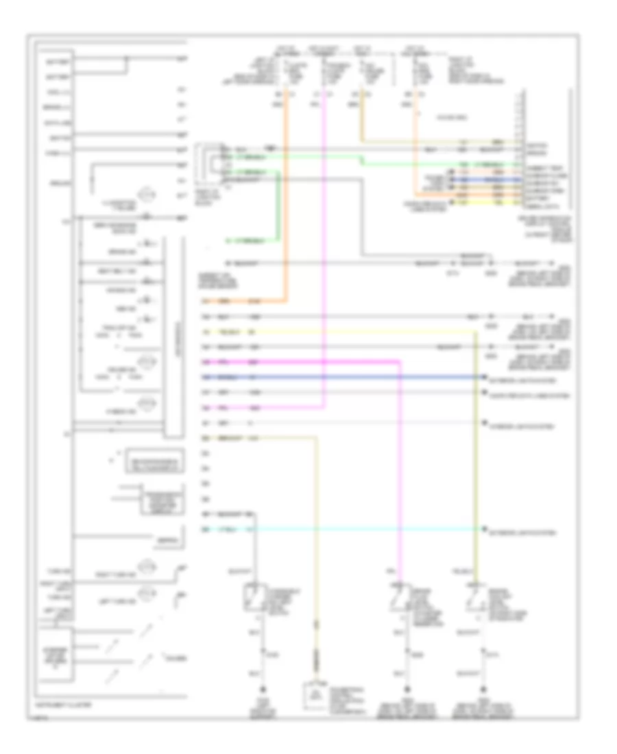
Instrument Cluster Wiring Diagram for Chevrolet Impala LS 2001
List of elements for Instrument Cluster Wiring Diagram for Chevrolet Impala LS 2001:
- 12v
- A/c- cruise fuse 10a
- Abs ind
- Air bag ind
- Ambient air temperature gauge sensor
- Ambient temp
- Battery
- Brake fluid level switch (in master cylinder reservoir)
- Brake ind
- Brake lvl
- C12
- Clstr/ bcm fuse 10a
- Computer data lines system
- Cool lvl
- Cruise ind
- Data line
- Dic/ rke fuse 10a
- Driver information display control module (in front center
- Eeprom
- Engine coolant level switch (on right side of radiator)
- Exterior lights system
- G108 (left radiator support)
- G202 (behind left side of dash, on left side of brake pedal bracket)
- G202 (behind left side of dash, on right side of brake pedal bracket)
- Gauges
- Ground
- Hi beam ind
- Hot at all times
- Hot in accy or run
- Hot in run
- Ignition
- Illumination (7 bulbs)
- Instrument cluster
- Interior lights system
- Led driver ic
- Left i/p junction block (end of dash in left door opening)
- Left turn ind
- Left turn input
- Mil cntl
- Of roof)
- Pcm/bcm/ clstr fuse 10a
- Power tops system
- Powertrain control module (pcm) (in air cleaner box)
- Re-configurable telltale display
- Right i/p junction block
- Right i/p junction block (end of dash in right door opening)
- Right turn ind
- Right turn input
- S150
- S174
- S229
- S236
- S253
- S322
- Seat belt ind
- Serial data
- Service engine soon ind
- Stepper motor drivers ic
- Sunroof close
- Sunroof open
- Sunroof sw
- Trac off ind
- Transmission position/ odometer display
- Turn ind
- W/o 9c1/9c3
- Wash lvl
- Windshield washer solvent level switch
INTERIOR LIGHTS
Courtesy Lamps Wiring Diagram (1 of 2) for Chevrolet Impala LS 2001
List of elements for Courtesy Lamps Wiring Diagram (1 of 2) for Chevrolet Impala LS 2001:
- A10
- A11
- Batt rundown protection relay
- Body control module (behind left side of dash)
- Crtsy lmp v
- Dic/ rke fuse 10a
- Dome
- Dome lmp sw
- Emergency vehicle interior lamp switch (w/ 9c1/9c3)
- G202 (behind left side of dash, on left side of brake pedal bracket)
- G202 (behind left side of dash, on right side of brake pedal bracket)
- G305 (at base of right "b" pillar)
- Ground
- H10
- Headlamp switch
- Hot at all times
- I/p brp fuse 10a
- I/p compartment lamp
- Inadvrt rly
- K10
- Left footwell courtesy lamp
- Left i/p junction block
- Off
- Rear compartment courtesy lamp
- Rear compartment lid ajar indicator switch
- Rear compartment occupant sensor
- Right footwell courtesy lamp
- Right i/p junction block
- S229 (i/p harn, behind right center of instrument cluster)
- S236
- S253
- S410
- S420
- S900
- Theater dim
- To splice s391 (diagram 2 of 2)
- Trk/roof brp fuse 15a
- W/ trap alert system
- W/o trap alert system
Courtesy Lamps Wiring Diagram (2 of 2) for Chevrolet Impala LS 2001
List of elements for Courtesy Lamps Wiring Diagram (2 of 2) for Chevrolet Impala LS 2001:
- (impala)
- (roof wiring harn, right front side of roof) s390
- A1 door ajar
- A10
- A12 door unlock
- A6 lock/unlock
- A7 lock/unlock
- A8 door open
- A8 theater dim
- Ajar
- Auxiliary dome lamp (9c1/9c3)
- B11
- B12
- B3 lock/unlock
- Body control module (behind left side of dash)
- C12
- D12
- Dome lamp (w/o c79)
- From right i/p junction block (diagram 1 of 2)
- G202 (behind left side of dash, on right side of brake pedal bracket)
- G305 (at base of right "b" pillar)
- Ground feed
- Inside rear view mirror
- Latch
- Left door lock switch
- Left front side door lock
- Left i/p junction block
- Left reading lamp assembly (w/ c79)
- Left rear side door lock
- Left vanity mirror lamp (dh6)
- Lock
- Nca
- Right door lock switch
- Right front door lock
- Right front side door lock
- Right i/p junction block
- Right reading lamp assembly (w/ c79)
- Right rear side door lock
- Right vanity mirror lamp (dh6)
- S253
- S322 (body harn, approx 10 cm from inflatable restraint driver seat module breakout)
- S328
- S391
- S392
- Secondary
- Tan
- Unlock
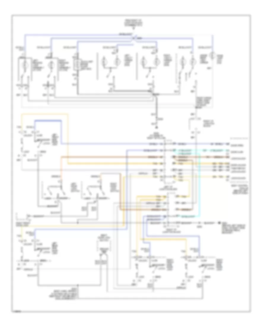
Instrument Illumination Wiring Diagram (1 of 2) for Chevrolet Impala LS 2001
List of elements for Instrument Illumination Wiring Diagram (1 of 2) for Chevrolet Impala LS 2001:
- (2000)
- (2000) (2001)
- (2001)
- A2 park lamp switch input c3
- B11
- Body control module (behind left side of dash)
- C1 c4
- C2 c5
- Full bright
- G202 (left side of dash)
- Ground
- H11
- H12
- Headlamp switch
- Hot at all times
- I/p dimming switch
- Inflatable restraint steering wheel module coil
- Int dim ctrl
- K11
- K12
- Left cruise control switch (set/ cancel)
- Left i/p junction block
- Left radio control (seek/ preset)
- Low dim off
- Off
- Park
- Park lamp relay
- Rear park lmp fuse 15a
- Red
- Relay ctrl
- Right cruise control switch (resume/ accel)
- Right i/p 1 fuse 60a
- Right i/p junction block
- Right radio control (volume/ mode)
- S236
- S253
- Steering column fuse 2a
- Steering wheel
- To hvac control module (diagram 2 of 2)
- To left i/p junction block (diagram 2 of 2)
- Underhood junction block (top)
Instrument Illumination Wiring Diagram (2 of 2) for Chevrolet Impala LS 2001
List of elements for Instrument Illumination Wiring Diagram (2 of 2) for Chevrolet Impala LS 2001:
- (2 door)
- (2000)
- (2001)
- (4 door)
- A10
- Ashtray lamp
- Ashtray lamp (impala)
- B10
- C1 e d
- C10
- C11
- C2 c3
- Dim input
- Electronic traction control switch
- Electronic traction control switch (impala)
- Emergency vehicle interior lamp switch
- Fog lamp switch
- From left i/p junction block (diagram 1 of 2)
- From left i/p junction block a (diagram 1 of 2)
- From left i/p junction block c (diagram 2 of 2)
- G202 (left side of dash)
- G305 (at base of right "b" pillar)
- G308 (at base of left "b" pillar)
- Ground
- Harn, in door)
- Hazard & turn signal lamp flasher
- Hvac control module
- Impala
- Instrument cluster
- K c2
- Left door lock switch
- Left front window switch
- Left i/p junction block
- Left seat heater switch
- Monte carlo
- Outside rear view mirror remote control switch
- Radio
- Right door lock switch
- Right i/p junction block
- Right seat heater switch
- Right side window switch
- S229
- S229 (i/p harn, behind right center of instrument cluster)
- S236
- S253
- S320
- S328
- S338 (console harn, front area of console)
- S504
- To left i/p junction block (diagram 2 of 2)
- Transmission position indicator lamp (prndl)
- W/ nw9
- W/o nw9
POWER DISTRIBUTION
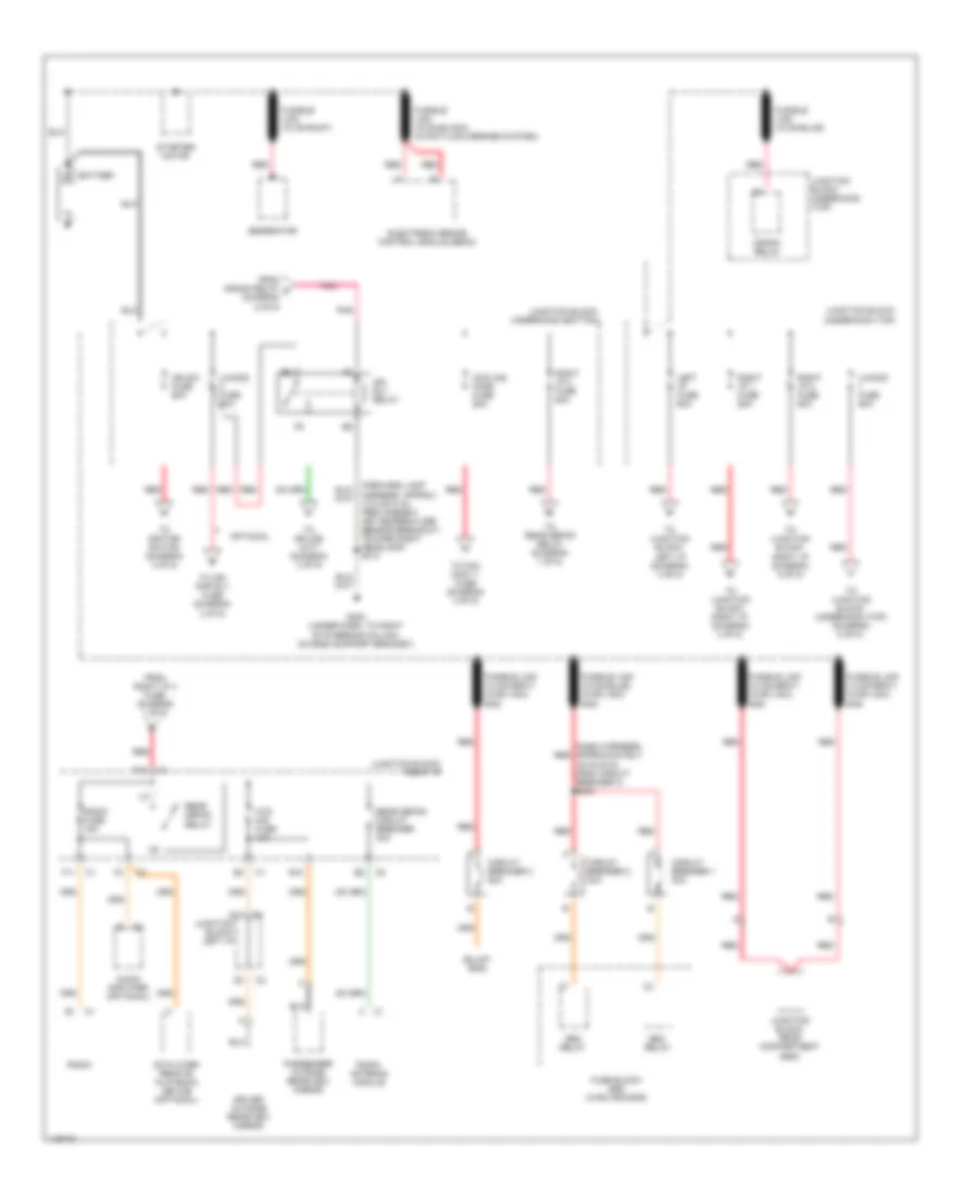
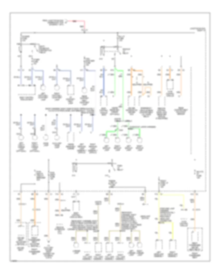
Power Distribution Wiring Diagram (1 of 5) for Chevrolet Impala LS 2001
List of elements for Power Distribution Wiring Diagram (1 of 5) for Chevrolet Impala LS 2001:
- (dash harness, approximately 16 cm (6 in) from circuit breaker 3) s244
- Audio amplifier (optional)
- B10
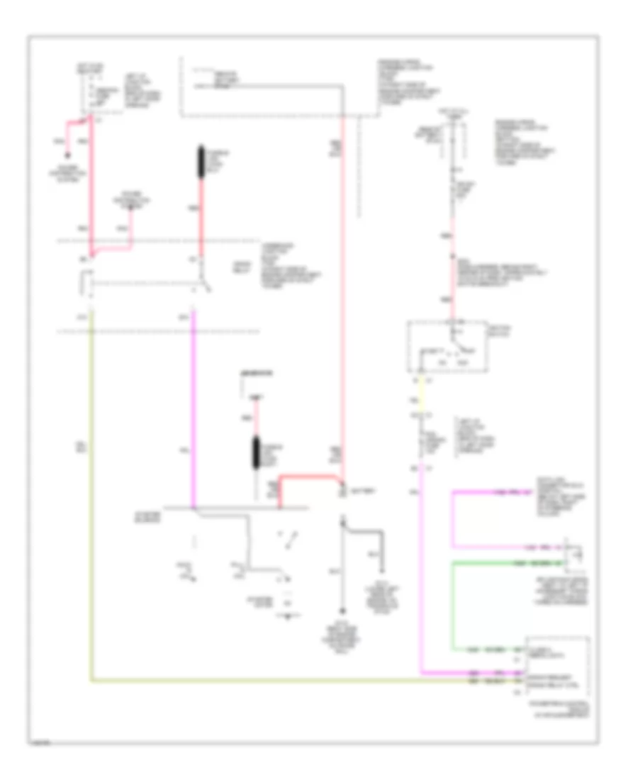
- Battery
- Cd player- remote playback device (optional)
- Circuit breaker 1 30a
- Circuit breaker 2 30a
- Circuit breaker 3 50a
- Cooling fans fuse 60a
- Crank relay
- D11
- Driver outside rearview mirror
- Electronic brake control module (ebcm)
- F10
- F11
- From crank relay o (diagram 2 of 5)
- From right i/p 3 fuse (diagram 1 of 5)
- Fuse block- seo (w/9c1/9c3/9c6)
- Fusible link (10 ga-rust)
- Fusible link (14 ga-gray) (w/9c1,9c3, 9c6)
- Fusible link (16 ga-black) (w/anti-lock brakes system)
- G202 (under dash, to right of steering column, on dash support bracket)
- Generator
- Harness, approx 10.5 cm (4 in) from ambient air temperature sensor breakout, toward right headlamp) s174
- Htd mir fuse 10a
- Ign rly relay
- Ign sw fuse 60a
- Junction block- left i/p
- Junction block- rear compartment (seo)
- Junction block- right i/p
- Junction block- underhood (bottom)
- Junction block- underhood (top)
- Left i/p fuse 60a
- Optional
- Passenger outside rearview mirror
- Pnk
- Radio
- Radio antenna module
- Radio fuse 15a
- Rear defog circuit breaker 30a
- Rear defog relay
- Red
- Right i/p 1 fuse 60a
- Right i/p 2 fuse 60a
- Right i/p 3 fuse 60a
- Seo relay
- Starter motor
- To air pmp rly fuse (diagram 3 of 5)
- To fan cont 1 fuse (diagram 3 of 5)
- To ignition switch (diagram 2 of 5)
- To junction block- left i/p (diagram 3 of 5)
- To junction block- right i/p (diagram 4 of 5)
- To junction block- right i/p (diagram 5 of 5)
- To junction block- underhood (top) (diagram 5 of 5)
- To rear defog relay (diagram 1 of 5)
- To splice s177 (diagram 3 of 5)
- U/hood fuse 60a
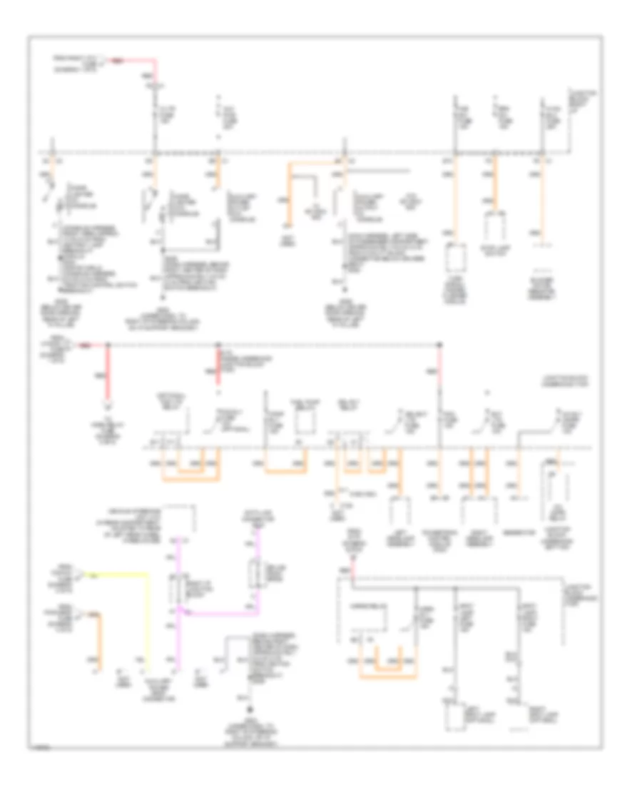
Power Distribution Wiring Diagram (2 of 5) for Chevrolet Impala LS 2001
List of elements for Power Distribution Wiring Diagram (2 of 5) for Chevrolet Impala LS 2001:
- (engine harness, lower left rear side of engine compartment) s169
- A/c cruise fuse 10a
- A/c fan fuse 20a
- A10
- A11
- A12
- Abs/pcm fuse 10a
- Acc
- Accy
- Air temperature actuator (manual a/c) left air temperature actuator (optional)
- Bcm fuse 10a
- Body control module (bcm)
- C201
- C373
- Cig/ aux fuse 10a
- Crank
- Crank relay
- Cruise control module (ccm)
- Cruise control on/off switch
- Cruise control release switch
- Cruise fuse 2a
- D11
- D12
- Driver information center (dic)
- Electronic brake control module (ebcm)
- Evaporative emissions canister vent solenoid
- F10
- From ign sw fuse (diagram 1 of 5)
- From ignition switch (diagram 2 of 5)
- Hvac control module
- Ign 0
- Ign 1
- Ign 3
- Ignition key alarm switch (closed with key in ignition switch)
- Ignition switch
- Ignition switch)
- Inflatable restraint sensing & diagnostic module (sdm)
- Inside rearview mirror
- Instrument panel cluster (ipc)
- Junction block- left i/p
- Junction block- underhood (top)
- Off
- Pcm (crank) fuse 10a
- Pcm/bcm clstr fuse 10a
- Pnk
- Powertrain control module (pcm)
- Rear compartment occupant sensor
- Red
- Right air temperature actuator (optional)
- S234 (dash harness, behind center of dash, approximately 32.5 cm (13 in) from red
- Srs fuse 10a
- Start
- Stop fuse 10a
- Stop lamp switch
- To auxiliary power drop connector (diagram 5 of 5)
- To cruise fuse (diagram 2 of 5)
- To ignition relay (diagram 1 of 5)
- To pcm (crank) fuse (diagram 2 of 5)
- To pcm/bcm/ clstr fuse (diagram 2 of 5)
- Turn signal fuse 15a
- Turn signal/ hazard flasher module
- W/anti-lock brakes
- W/display driver information center
- W/o anti-lock brakes
- Warning systems
- Windshield wiper system module
- Windshield wiper/ washer switch
- Wsw fuse 25a
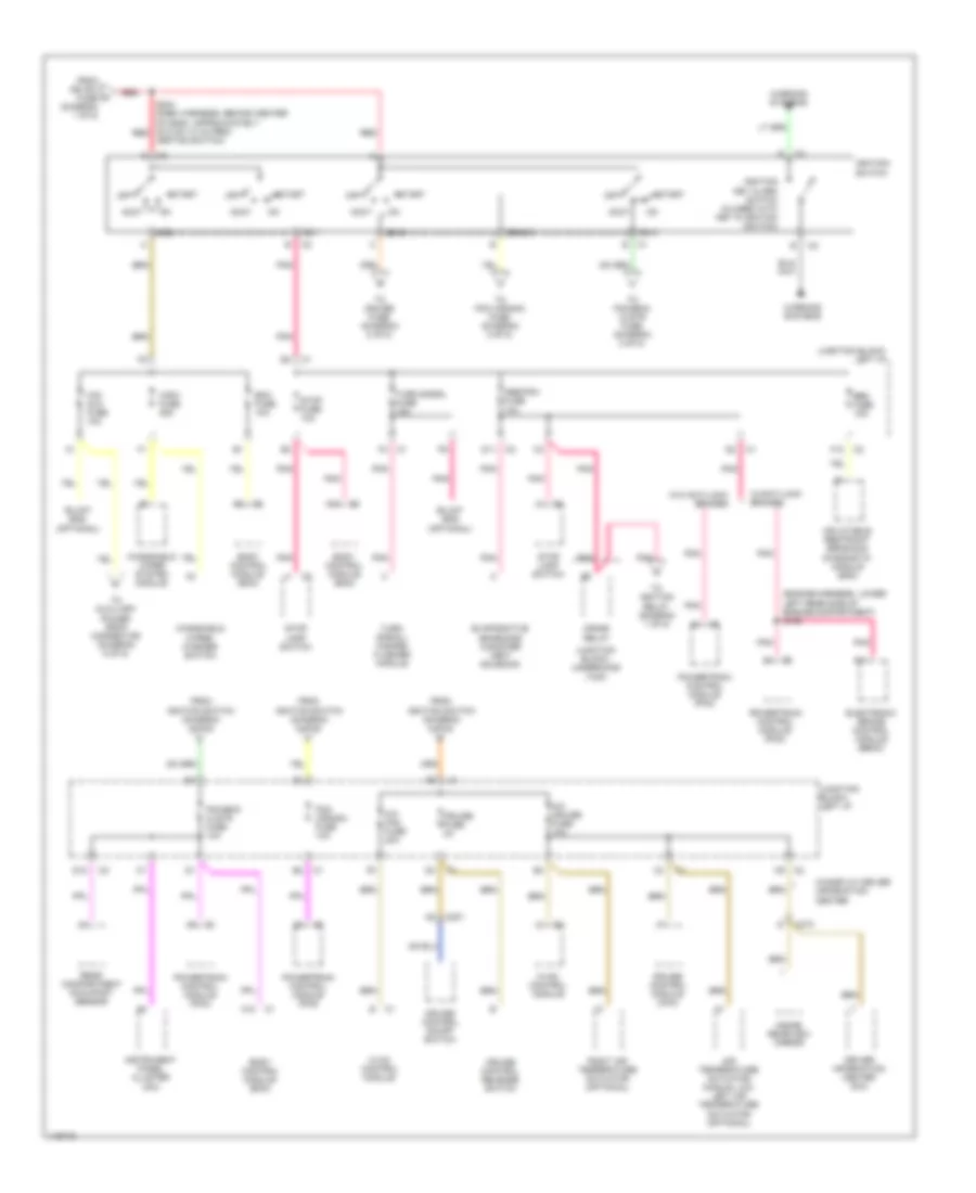
Power Distribution Wiring Diagram (3 of 5) for Chevrolet Impala LS 2001
List of elements for Power Distribution Wiring Diagram (3 of 5) for Chevrolet Impala LS 2001:
- (3.8l-engine harness at egr valve breakout) (3.4l-engine harness, left front of engine compartment, approximately 10.5 cm (4 in) from 24 cavity black in-line connector) s157
- (dash harness, behind left side of dash, approx. 4 cm (2 in) from body computer module breakout) s236
- (diagram 1 of 5)
- (engine harness, right front of engine approx. 4.7 cm (2 in) from 24 cavity black in-line connector between engine harness & forward lamp harness) (3.8l)s131
- (forward lamp harness, approximately 4 cm (2 in) from breakout for ambient air temperature sensor, toward right headlamp) s130
- (under dash, to right of steering column, on i/p support bracket) g202
- 1-2 shift solenoid (1-2 ss) valve
- 2-3 shift solenoid (2-3 ss) valve
- 3.4l
- 3.8l
- A.i.r. relay
- A/c cmpr relay
- A/c rly (coil) fuse 10a
- A12
- Air pmp rly fuse 30a
- Air rly relay (optional)
- Automatic transaxle
- Body control module (bcm)
- C1 b
- C1 e11
- C11
- C113
- C12 c1
- C2 b (3.4l)
- C311
- Clstr/ bcm fuse 10a
- Data link connector (dlc)
- Dfi mdl fuse 15a
- Dr lk fuse 20a
- Driver heated seat relay
- Driver seat
- Driver window switch
- E1 c2
- Eng devices fuse 10a
- Evaporative emission (evap) canister purge solenoid
- F11
- F12
- Fan cont 1 fuse 25a
- Fan cont 1 relay
- Fan cont 2 & 3 fuse 25a
- Fan cont 2 relay
- Fan cont 3 relay
- From cooling fans fuse (diagram 1 of 5)
- From ign rly relay c
- From left i/p fuse (diagram 1 of 5)
- From u/hood 2 fuse (diagram 1 of 5)
- Front passenger window switch
- Fuel inj fuse 15a
- Fuel injector
- Head- lamp relay
- Heated oxygen sensor (ho2s) sensor 1
- Heated oxygen sensor (ho2s) sensor 2
- If equipped
- Ignition control module (icm)
- Impala
- Instrument panel cluster (ipc)
- Junction block (underhood (bottom)
- Junction block- left i/p
- Junction block- right i/p
- Junction block- underhood (bottom)
- Junction block- underhood (top)
- Lh htd st/bcm fuse 15a
- Mass air flow (maf) sensor
- Monte carlo
- Nca
- Outside rearview mirror switch
- Oxy sen fuse 15a
- P (3.8l)
- Pnk
- Pnk (3.8l: engine harness, engine near iat sensor) s109 (3.4l: engine harn, on left side of engine compt. approx (2 in) from pcm breakout)
- Pwr mir fuse 2a
- Red
- Red s115
- Retained accsry power relay
- Retained accsry pwr brkr circuit breaker 30a
- S132 (inside underhood junction block (top))
- S179 (inside underhood junction block (top))
- Secondary air injection (air) solenoid
- Sunroof module (if equipped)
- Torque converter clutch (tcc) solenoid valve
- Trans sol fuse 10a
Power Distribution Wiring Diagram (4 of 5) for Chevrolet Impala LS 2001
List of elements for Power Distribution Wiring Diagram (4 of 5) for Chevrolet Impala LS 2001:
- (rear body harness, right side of rear compartment, approximately (19.5 cm) (7 in) from grommet right rear corner of rear compartment) s400
- (roof harness, right side of roof approximately 12.5 cm (5 in) from dome lamp breakout, toward rear of roof) s391
- A11
- A12 c2
- Auxiliary dome lamp
- B/u lp fuse 10a
- Backup lp relay
- Batt rundown protection relay
- Body control module (bcm)
- C1 d4
- C2 e8
- C2 f10
- C311
- C312
- C400
- Connector) s176
- D10
- D9 c2
- Dic/rke fuse 10a
- Dome lamp
- Driver information center (dic)
- Driver seat
- Driver seat adjuster switch
- E16
- E3 c1
- E5 c2
- Emergency vehicle rear compartment lid lamps relay
- F1 c1
- F12
- F4 c1
- From junction block- underhood (top) (diagram 1 of 5)
- Front park lp fuse 15a
- Front passenger heated seat relay
- Front passenger seat
- Front passenger seat adjuster switch
- H10
- H11
- H12
- Headlamp switch
- Hvac control module
- I/p brp fuse 10a
- I/p compart- ment lamp
- If equipped
- Impala
- Inside rearview mirror
- Inside rearview mirror (optional)
- Junction block- right i/p
- K10
- K11
- K12
- L10
- Left backup lamp
- Left footwell courtesy lamp
- Left headlamp assembly
- Left license lamp
- Left reading lamp assembly (impala)
- Left tail lamp assembly
- Left vanity mirror lamp (optional)
- License lamp
- Monte carlo
- N10
- Nca
- Park lp relay
- Pwr drop fuse 15a
- Pwr seats circuit breaker 30a
- Rear compart- ment courtesy lamp
- Rear compartment occupant sensor
- Rear prk lp fuse 15a
- Red
- Remote control door lock receiver (rcdlr) (if equipped)
- Rh htd st fuse 15a
- Right backup lamp
- Right footwell courtesy lamp
- Right headlamp assembly
- Right license lamp
- Right reading lamp assembly (impala)
- Right tail lamp assembly
- Right vanity mirror lamp (optional)
- To auxiliary power drop connector (diagram 5 of 5)
- Trk/ roof brp fuse 15a
- Vehicle interface unit (viu)
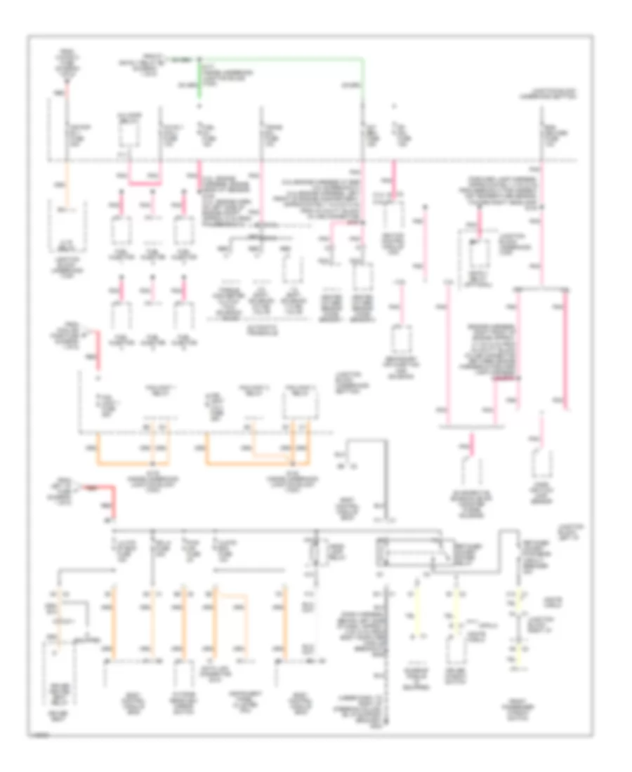
Power Distribution Wiring Diagram (5 of 5) for Chevrolet Impala LS 2001
List of elements for Power Distribution Wiring Diagram (5 of 5) for Chevrolet Impala LS 2001:
- (diagram 1 of 5)
- (not used)
- (optional) fog lts relay
- A/c cmpr relay
- A/c rly (cmpr) fuse 10a
- Approximately 6.5 cm (2 in) from 8 cavity black connector below driver's seat) s320
- Aux pwr fuse 20a
- Auxiliary power drop connector
- Auxiliary power outlet (w/o console)
- Auxiliary power output (w/ console)
- Blower motor resistor assembly
- Brk sw fuse 15a
- C/ltr fuse 15a
- C122
- Cigar lighter (w/ console)
- Cigar lighter (w/o console)
- Data link connector (dlc)
- Drl rly relay
- Drl/ext lts fuse 15a
- E10
- E11
- Ext lts fuse 10a
- F/pmp rly fuse 15a
- F11
- Fog rly fuse 10a (optional)
- From cig/aux fuse (diagram 2 of 5)
- From ignition switch breakout) s229
- From pwr drop fuse (diagram 4 of 5)
- From right i/p 2 fuse h
- From s178 (diagram 5 of 5)
- From u/hood 1 fuse (diagram 1 of 5)
- Fuel pump relay
- G202 (under dash, to right of steering column, on i/p support bracket)
- G309 (below driver door opening, rear of left "a" pillar)
- Generator
- Haz sw fuse 15a
- Horn rly fuse 15a
- Horns relay
- Hvac blo fuse 25a
- Junction block- right i/p
- Junction block- underhood (bottom)
- Junction block- underhood (top)
- Left headlamp assembly
- Left- spot lamp (optional)
- Nca
- Pcm fuse 15a
- Powertrain control module (pcm)
- Red
- Right headlamp assembly
- Right i/p junction block
- Right- spot lamp (optional)
- S178 (inside underhood junction block (top)) red
- Splice pack- sp205
- Spot lamp- left fuse 15a
- Spot lamp- right fuse 15a
- Stop lamp switch
- To horn relay fuse (diagram 5 of 5)
- Turn signal/ hazard flasher module
- Vehicle interface unit (viu) (in rear compartment, mounted to rear of left rear wheel wheelhouse)
- W/ 9c1/9c3/ 9c8
- W/9c1/9c3
- W/o 9c1/9c3/ 9c8
POWER DOOR LOCKS
Power Door Lock Wiring Diagram for Chevrolet Impala LS 2001
List of elements for Power Door Lock Wiring Diagram for Chevrolet Impala LS 2001:
- (2000)
- (2000) (2001)
- (2001)
- A10
- A11
- A12
- Acc sig in
- Ajar
- B11
- B12
- Battery
- Bcm fuse 10a
- Body control module (behind left side of dash)
- C3 c2
- Clstr/bcm fuse 10a
- Ctsy
- D12
- Dic/rke fuse 10a
- Door ajar in
- Door lock
- Down
- Dr lk fuse 20a
- Dr lk/unlk
- Driver door lock switch
- E12
- Front passenger door lock switch
- G202 (on left side of brake pedal bracket)
- G202 (on right side of brake pedal bracket)
- Ground
- Hot at all times
- Hot in on or acc
- Hot in on or start
- Ignition 0
- Ignition 1
- Illum entry
- Interior lights system
- Latch
- Left door lock cylinder switch
- Left i/p fuse block
- Lf dr lk/unlk
- Lf dr open in
- Lh htd seat/bcm fuse 15a
- Lk/unlk in
- Lock
- Ohms
- Pcm/bcm/ clstr fuse 15a
- Pnk
- Power distrib- ution system
- Power distribution system
- Remote control door lock receiver (upper center of dash)
- Right door lock cylinder switch
- Right i/p fuse block
- S236
- S253
- S322
- Serial data sig
- Stop fuse 10a
- Tan
- Trunk rel ctrl
- Trunk/tailgate/ fuel doors system
- Un- lock
- Unlock
POWER MIRRORS
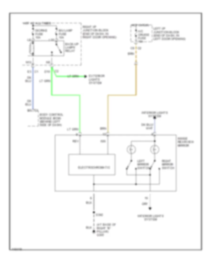
Electrochromic Mirror Wiring Diagram for Chevrolet Impala LS 2001
List of elements for Electrochromic Mirror Wiring Diagram for Chevrolet Impala LS 2001:
- (at base of right "b" pillar) g305
- A/c cruise fuse 10a
- B/u lamp fuse 10a
- B6 c1
- Back-up lamps relay
- Body control module (bcm) (behind left side of dash)
- C9 c2
- D10
- Dic/rke fuse 10a
- E3 c1
- Electrochromatic
- Exterior lights system
- Hot at all times
- Hot in run
- Ign
- Inside rearview mirror
- Interior lights system
- L10
- Left i/p junction block (end of dash, in left door opening)
- Left mirror switch
- N10
- Rev
- Right i/p junction block (end of dash, in right door opening)
- Right mirror switch
- S392
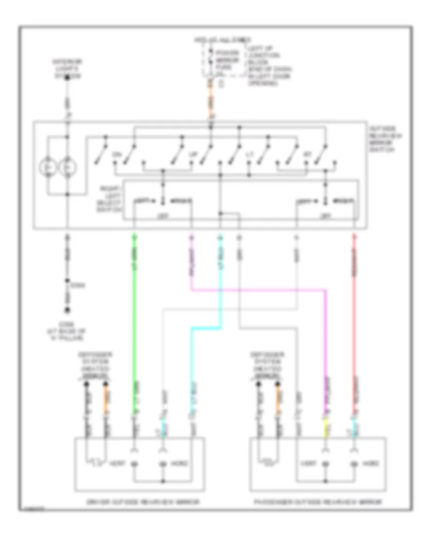
Power Mirror Wiring Diagram for Chevrolet Impala LS 2001
List of elements for Power Mirror Wiring Diagram for Chevrolet Impala LS 2001:
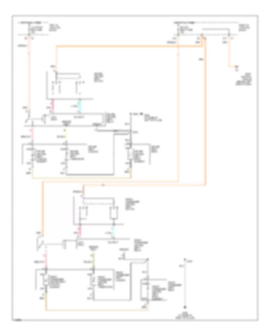
- Defogger system (heated mirror)
- Driver outside rearview mirror
- G308 (at base of "a" pillar)
- Horz
- Hot at all times
- Interior lights system
- Left
- Left i/p junction block (end of dash, in left door opening)
- Off
- Outside rearview mirror switch
- Passenger outside rearview mirror
- Power mirror fuse 2a
- Right
- Right/ left select switch
- S504
- Vert
POWER SEATS
Heated Seats Wiring Diagram for Chevrolet Impala LS 2001
List of elements for Heated Seats Wiring Diagram for Chevrolet Impala LS 2001:
- A12
- Body control module (behind left side of dash)
- D11
- Driver heated seat back element
- Driver heated seat cushion element
- Driver heated seat relay
- Driver heated seat switch
- Driver heated seat thermistor
- Driver seat back
- Driver seat cushion
- Front passenger heated seat back element
- Front passenger heated seat dushion element
- Front passenger heated seat relay
- Front passenger heated seat switch
- Front passenger heated seat thermistor
- Front passenger seat back
- Front passenger seat cushion
- G305 (at base of right "b" pillar)
- G308 (at base of left "b" pillar)
- Ground
- Hot at all times
- Left i/p junction block
- Lh htd st/ bcm fuse 15a
- Lo/hi input
- Nca
- On input
- Pnk
- Rh htd seat fuse 15a
- Right i/p junction block
- S330
- S333
- Sensor input
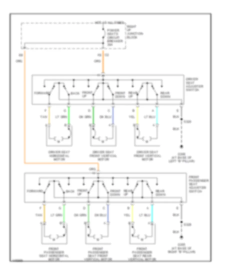
Power Seats Wiring Diagram for Chevrolet Impala LS 2001
List of elements for Power Seats Wiring Diagram for Chevrolet Impala LS 2001:
- Back
- C2 f8
- Driver seat adjuster switch
- Driver seat front vertical motor
- Driver seat horizontal motor
- Forward
- Front down
- Front passenger seat adjuster switch
- Front passenger seat front vertical motor
- Front passenger seat horizontal motor
- Front passenger seat rear vertical motor
- Front up
- G305 (at base of right "b" pillar)
- G308 (at base of left "b" pillar)
- Hot at all times
- Power seats circuit breaker 30a
- Rear down
- Rear up
- Right i/p junction block
- S320
- S328
- Tan
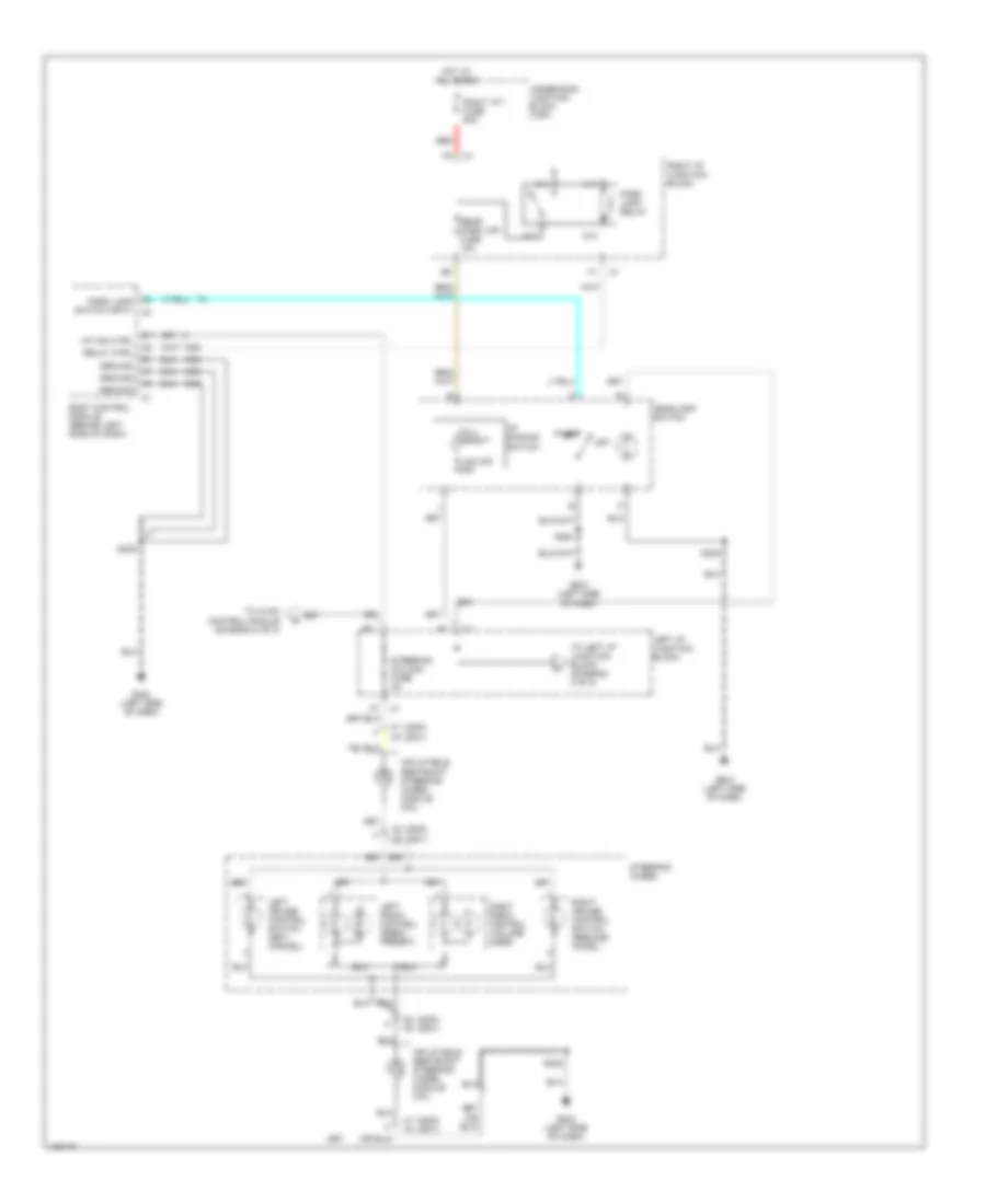
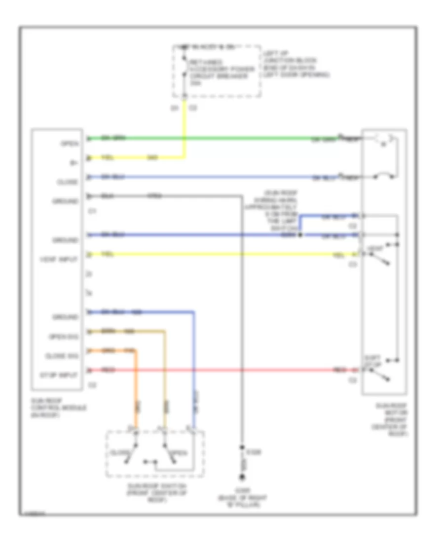
POWER TOP/SUNROOF
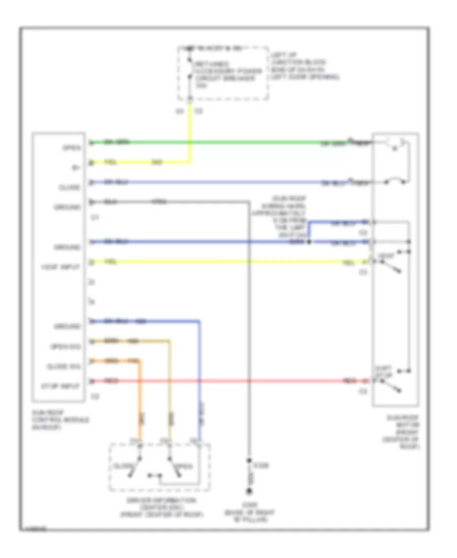
Power Top/Sunroof Wiring Diagrams, with DIC for Chevrolet Impala LS 2001
List of elements for Power Top/Sunroof Wiring Diagrams, with DIC for Chevrolet Impala LS 2001:
- (sun roof wiring harn, approximately 9 cm from the limit switch) s399
- Close
- Close sig
- Driver information center (dic) (front center of roof)
- G305 (base of right "b" pillar)
- Ground
- Hot in accy & on
- Left i/p junction block (end of dash in left door opening)
- Nca
- Open
- Open sig
- Red
- Retained accessory power circuit breaker 30a
- S328
- Soft stop
- Stop input
- Sun roof control module (in roof)
- Sun roof motor (front center of roof)
- Vent
- Vent input
Power Top/Sunroof Wiring Diagrams, without DIC for Chevrolet Impala LS 2001
List of elements for Power Top/Sunroof Wiring Diagrams, without DIC for Chevrolet Impala LS 2001:
- (sun roof wiring harn, approximately 9 cm from the limit switch) s399
- Close
- Close sig
- G305 (base of right "b" pillar)
- Ground
- Hot in accy & on
- Left i/p junction block (end of dash in left door opening)
- Nca
- Open
- Open sig
- Red
- Retained accessory power circuit breaker 30a
- S328
- Soft stop
- Stop input
- Sun roof control module (in roof)
- Sun roof motor (front center of roof)
- Sun roof switch (front center of roof)
- Vent
- Vent input
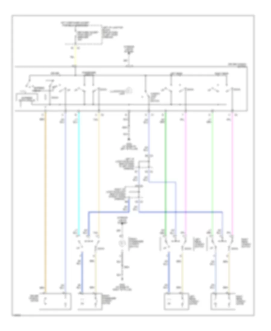
POWER WINDOWS
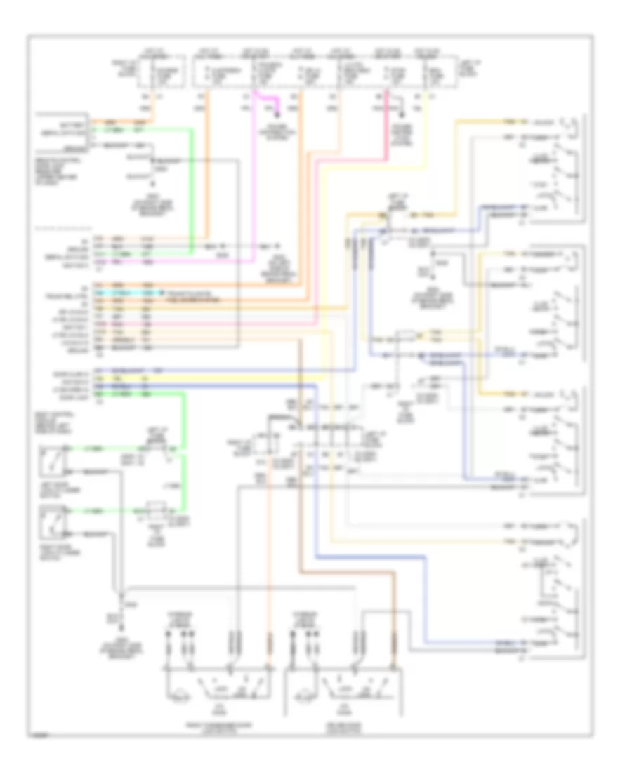
Power Window Wiring Diagram for Chevrolet Impala LS 2001
List of elements for Power Window Wiring Diagram for Chevrolet Impala LS 2001:
- A6 c2
- B6 c2
- C1 a4
- C2 a9
- Down
- Driver
- Driver window motor
- Driver window switch
- Express down
- Express down module
- Front passenger window motor
- Front passenger window switch
- G305 (at base of right "b" pillar)
- G308 (at base of left "b" pillar)
- Hot w/retained accsry pwr relay energized
- Illumination lamp
- Interior lights system
- Left i/p junction block (end of dash in left door opening)
- Left rear
- Left rear window motor
- Left rear window switch
- Passenger front
- Retained accsry pwr circuit breaker 30a
- Right i/p junction block (end of dash in right door opening)
- Right rear
- Right rear window motor
- Right rear window switch
- S504
- S604
- Tan
- Window lock out switch
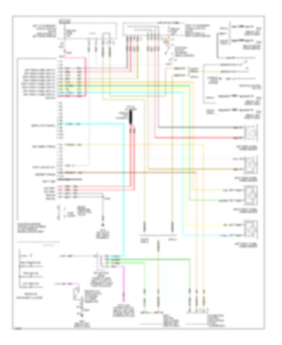
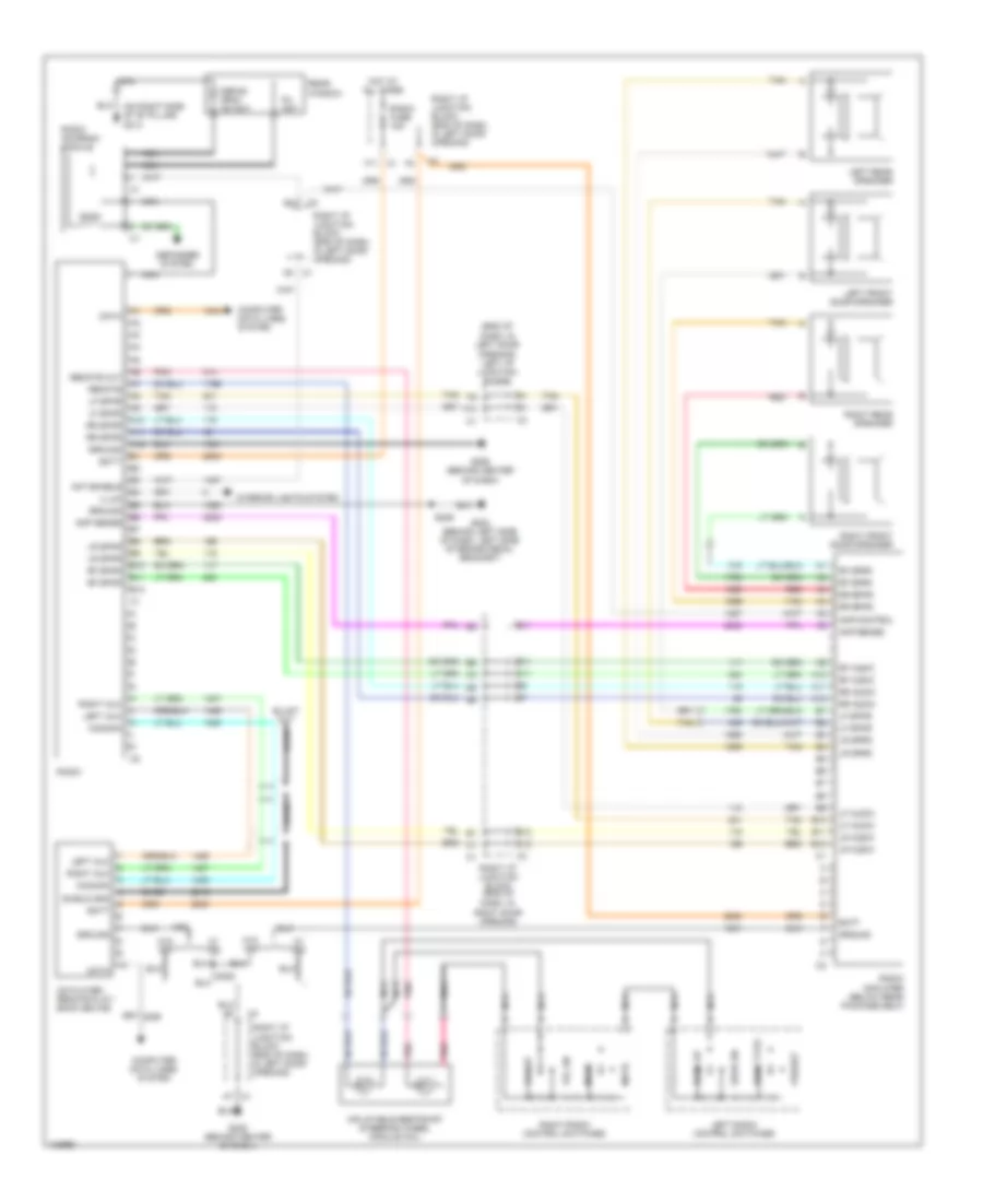
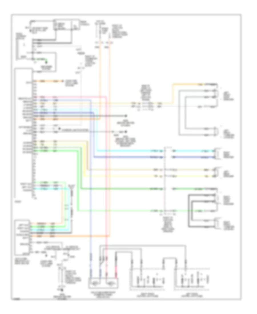
RADIO
Radio Wiring Diagrams, with Amplifier for Chevrolet Impala LS 2001
List of elements for Radio Wiring Diagrams, with Amplifier for Chevrolet Impala LS 2001:
- (end of dash, in left door opening) left i/p junction block
- (on right side of "b" pillar) g313
- A10
- A11
- A12
- A7 c1
- Amp control
- Amp sense
- Ant enable
- B10
- B11
- B12
- Bare
- Batt
- C1 a5
- C11
- C12
- Cd player- remote play- back device
- Common
- Computer data lines system
- Data
- Defog grid/ am ant
- Defogger system
- F10
- F11 c1
- Fm ant
- G202 (behind left side of dash, left side of brake pedal bracket)
- G206 (behind center of dash)
- Ground
- Hot at all times
- Illum
- Inflatable restraint steering wheel module coil
- Interior lights system
- Left aux
- Left front door speaker
- Left radio control switches
- Left rear speaker
- Lf audio
- Lf spkr
- Lr audio
- Lr spkr
- Mode
- Mute
- Nca
- Pnk
- Preset
- Radio
- Radio amplifier (below rear package self)
- Radio antenna module
- Radio fuse 15a
- Rear window
- Red
- Remote
- Remote out
- Rf audio
- Rf spkr
- Right aux
- Right door opening)
- Right front door speaker
- Right i/p junction block (end of dash, in
- Right i/p junction block (end of dash, in left door opening)
- Right radio control switches
- Right rear speaker
- Rr audio
- Rr spkr
- S229
- Seek dn
- Seek type
- Seek up
- Shield gnd
- Tan
- Vol dn
- Vol up
- W/ viu
- W/o viu
Radio Wiring Diagrams, with SEO for Chevrolet Impala LS 2001
List of elements for Radio Wiring Diagrams, with SEO for Chevrolet Impala LS 2001:
- (end of dash, in left door opening) left i/p junction block
- (on right side of "b" pillar) g313
- A10
- A11
- A12
- A5 c1
- A7 c1
- Ant enable
- B10
- B11
- B12
- Bare
- Batt
- C11
- C12
- C3 a6
- Cd player- remote play- back device
- Common
- Computer data lines system
- Data
- Defog grid/ am ant
- Defogger system
- F10
- F11 c1
- Fm ant
- G202 (behind left side of dash, left side of brake pedal bracket)
- G206 (behind center of dash)
- Ground
- Hot at all times
- Illum
- Inflatable restraint steering wheel module coil
- Interior lights system
- Left aux
- Left front door speaker
- Left radio control switches
- Left rear speaker
- Lf spkr
- Lr spkr
- Mode
- Mute
- Nca
- Pnk
- Preset
- Radio
- Radio antenna module
- Radio fuse 15a
- Rear window
- Remote
- Remote out
- Rf spkr
- Right aux
- Right front door speaker
- Right i/p junction block (end of dash, in right door opening)
- Right i/p junction block (end of dash, in right door opening)
- Right radio control switches
- Right rear speaker
- Rr spkr
- S229
- S380
- Seek dn
- Seek type
- Seek up
- Shield gnd
- Tan
- Vol dn
- Vol up
- W/ vehicle interface unit
- W/o vehicle interface unit
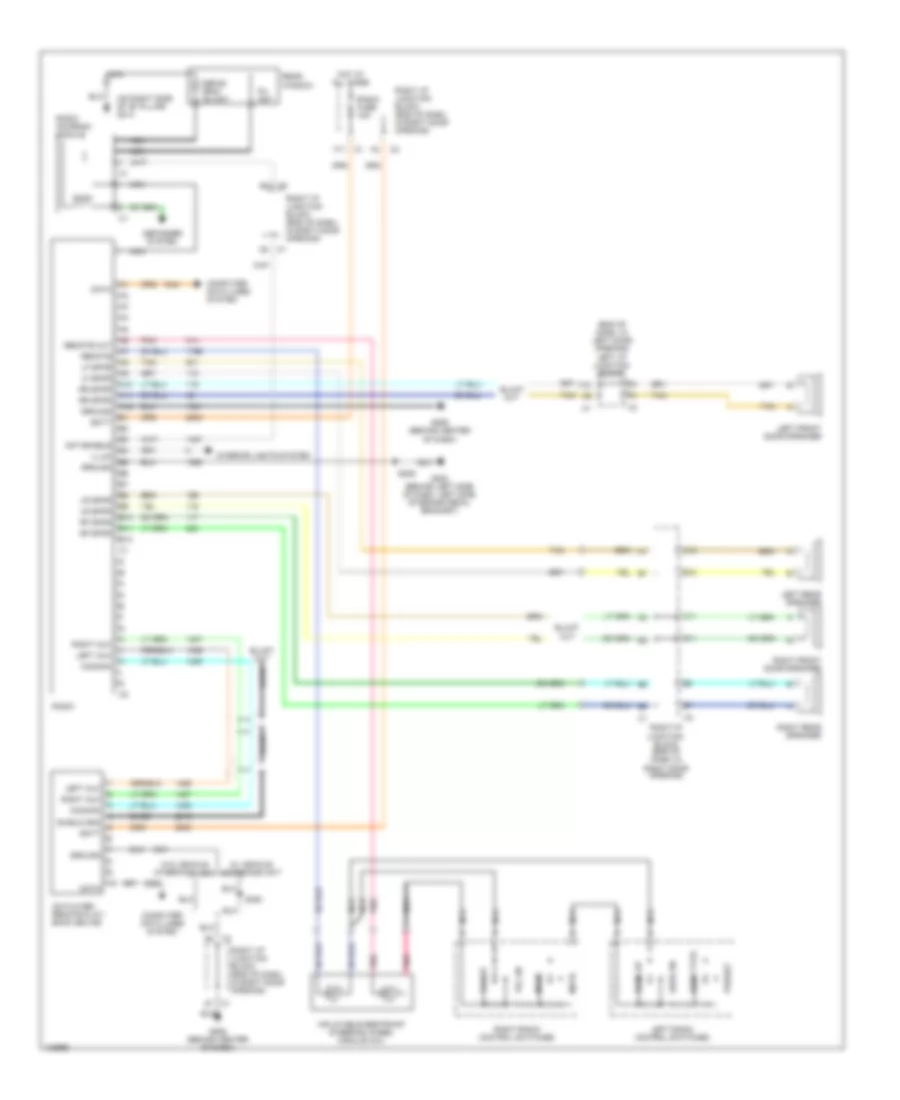
Radio Wiring Diagrams, without Amplifier for Chevrolet Impala LS 2001
List of elements for Radio Wiring Diagrams, without Amplifier for Chevrolet Impala LS 2001:
- (end of dash, in left door opening) left i/p junction block
- (on right side of "b" pillar) g313
- A10
- A11
- A12
- A5 c1
- A7 c1
- A8 c3
- Ant enable
- B10
- B11
- B12
- Bare
- Batt
- C11
- C12
- C3 a6
- Cd player- remote play- back device
- Common
- Computer data lines system
- Data
- Defog grid/ am ant
- Defogger system
- F10
- F11 c1
- F2 c3
- Fm ant
- G202 (behind left side of dash, left side of brake pedal bracket)
- G206 (behind center of dash)
- Ground
- Hot at all times
- Illum
- Inflatable restraint steering wheel module coil
- Interior lights system
- Left aux
- Left front door speaker
- Left front tweeter (uplevel)
- Left radio control switches
- Left rear speaker
- Lf spkr
- Lr spkr
- Mode
- Mute
- Nca
- Pnk
- Preset
- Radio
- Radio antenna module
- Radio fuse 15a
- Rear window
- Remote
- Remote out
- Rf spkr
- Right aux
- Right front door speaker
- Right front tweeter (uplevel)
- Right i/p accessory wiring junction block
- Right i/p junction block (end of dash, in right door opening)
- Right radio control switches
- Right rear speaker
- Rr spkr
- S229
- S380
- Seek dn
- Seek type
- Seek up
- Shield gnd
- Tan
- Vol dn
- Vol up
- W/ vehicle interface unit
- W/o vehicle interface unit
SHIFT INTERLOCKS
Shift Interlock Wiring Diagram for Chevrolet Impala LS 2001
List of elements for Shift Interlock Wiring Diagram for Chevrolet Impala LS 2001:
- A/t shift lock control solenoid (in center console)
- A/t shift lock control solenoid (in steering column)
- A10
- Body control module (behind left side of dash)
- Btsi solenoid control
- D10
- Hot in on, bulb test & start
- Ignition signal input
- Left i/p junction block (left end of dash)
- Pnk
- Powertrain control module (in air cleaner box)
- Signal (serial data)
- Splice pack sp205 (left side of dash)
- Stop fuse 10a
- Stoplamp switch (on brake pedal support) c2
- Transmission gear position
- W/ column shift
- W/ console shift
STARTING/CHARGING
Charging Wiring Diagram for Chevrolet Impala LS 2001
List of elements for Charging Wiring Diagram for Chevrolet Impala LS 2001:
- (2000 only)
- (not used)
- A/c rly (cmpr) fuse 10a
- Battery
- Charge warning indicator (red)
- Class 2 serial data
- Computer data lines
- F terminal monitor
- Fusible link (10 ga- rust)
- G114 (lower left rear of engine, on transaxle stud)
- G118 (right side of engine compartment, on frame rail)
- Generator
- Generator turn on signal
- Hot at all times
- Hot in acc, on or start
- Instrument cluster
- Left i/p junction block (end of dash in left door opening)
- Pcm/bcm/clstr fuse 10a
- Power distribution system
- Powertrain control module (pcm) (in air cleaner box)
- Red
- Splice pack sp205 (next to left i/p accessory wiring junction block wiring harness, taped on harness)
- Starter solenoid
- Underhood junction block (top) (in right side of engine compartment, forward of strut tower)
Starting Wiring Diagram for Chevrolet Impala LS 2001
List of elements for Starting Wiring Diagram for Chevrolet Impala LS 2001:
- Abs/pcm fuse 10a
- Acc
- B10
- Batt
- Battery
- C10
- Class 2 serial data
- Crank relay
- Crank relay ctrl
- Crank request
- Data link connector (dlc) (partial) (below left side of dash, right of steering column)
- Engine wiring harness junction block (bottom) (in right side of engine compartment, forward of strut tower)
- Engine wiring harness junction block (top) (in right side of engine compartment, forward of strut tower)
- Fusible link (10-ga rust)
- G114 (lower left rear of engine, on transaxle stud)
- G118 (right side of engine compartment, on frame rail)
- Generator
- Hold- in coil
- Hot at all times
- Hot in on or start
- Ign sw fuse 60a
- Ignition switch
- Left i/p junction block (end of dash, in left door opening)
- Off
- Pcm (crank) fuse 10a
- Pnk
- Power distribution system
- Powertrain control module (in air cleaner box)
- Pull- in coil
- Red
- Remote battery stud
- S234 (dash harness, behind right center of dash, approximately 15 cm (6 in) from ignition switch breakout)
- Splice pack sp205 (next to left i/p accessory wiring junction block, taped on harness)
- Start
- Starter motor
- Starter solenoid
- Underhood junction block (top) (in right side of engine compartment, forward of strut tower)
SUPPLEMENTAL RESTRAINTS
Supplemental Restraint Wiring Diagram for Chevrolet Impala LS 2001
List of elements for Supplemental Restraint Wiring Diagram for Chevrolet Impala LS 2001:
- (below driver door opening, rear of left "a" pillar) g309
- A10
- A11
- A12
- A13
- A14
- A15
- A16
- A17
- A18
- Air bag indicator
- C1 a1
- C217 a1
- Class 2 serial data
- Data link connector (dlc) (partial) (below left side of dash, right of steering column)
- Driver seat
- F10
- G309 (below driver door opening, rear of left "a" pillar)
- Ground
- High control
- Hot in on & start
- If equipped
- Ignition
- Inflatable restraint front end discriminating sensor
- Inflatable restraint i/p module
- Inflatable restraint sensing & diagnostic module (below passenger's seat)
- Inflatable restraint steering wheel module
- Inflatable restraint steering wheel module coil
- Instrument panel cluster (ipc)
- Left front inflatable restraint side impact module
- Left i/p accessory wiring junction block (end of dash in left door opening)
- Left inflatable restraint side impact sensor (impala: on left "b" pillar) (monte carlo: in driver's door)
- Left instrument panel fuse block (end of dash, in left door opening)
- Left seat belt switch
- Left signal
- Low control
- Nca
- Pnk
- Right i/p accessory wiring junction block (end of dash in right door opening)
- S330
- Sensor signal
- Shorting bar
- Signal
- Solid state
- Splice pack sp205 (in i/p harness, to right of park brake lever, taped over completely, between two strips of white tape)
- Srs fuse 10a
- Stage 1
- Stage 2
- Tan
- Voltage
TRANSMISSION
3.4L
3.4L VIN E, A/T Wiring Diagram for Chevrolet Impala LS 2001
List of elements for 3.4L VIN E, A/T Wiring Diagram for Chevrolet Impala LS 2001:
- (3.4l)
- (3.8l)
- (below dash, right side of steering column) data link connector
- (fuel inj harn, near breakout to map sensor) s121
- 1-2 shift sol
- 2-3 shift sol
- 3.8l 3.4l
- 5v reference a
- A/t iss sensor hi
- A/t iss sensor lo
- Abs/ pcm fuse 10a
- Automatic transaxle (4t65-e)
- Automatic transaxle fluid pressure manual valve position switch
- Automatic transaxle fluid temperature sensor
- Automatic transaxle input shaft speed sensor
- Battery in
- Brake switch in
- Ect sensor in
- Engine coolant temperature sensor (left rear of engine, near coolant outlet)
- G113 (lower left of engine, on transaxle stud)
- Hot at all times
- Hot in on or start
- I/p junction block (left) (left side of dash)
- Ignition in
- Instrument panel cluter
- Malfunction indicator lamp
- Map sensor
- Mil ctrl
- Park/neutral position (pnp) switch
- Pc sol hi
- Pc sol lo
- Pcm fuse 15a
- Pcm ground
- Pcm/bcm/ cluster fuse 10a
- Pnk
- Powertrain control module (in air cleaner box)
- Pressure control sol
- Red
- Rev
- S106
- Sensor ground
- Sensor return
- Serial data
- Splice pack sp205 (taped to harness, left end of dash)
- Stop lamp switch
- Tan
- Tcc pwm sol
- Tcc release
- Tcc release in
- Tcc/ brake switch
- Tft sensor in
- Throttle position sensor (on throttle body assembly)
- Tps in
- Tr sw in-a
- Tr sw in-b
- Tr sw in-c
- Tr sw in-p
- Trans range a in
- Trans range b in
- Trans range c in
- Trans sol fuse 10a
- Underhood junction block (bottom) (front of right strut tower)
- Vehicle speed sensor (lower right rear of engine compt, end of transaxle)
- Vss hi (signal)
- Vss lo (ground)
3.8L
3.8L VIN K, A/T Wiring Diagram for Chevrolet Impala LS 2001
List of elements for 3.8L VIN K, A/T Wiring Diagram for Chevrolet Impala LS 2001:
- (3.4l)
- (3.8l)
- (below dash, right side of steering column) data link connector
- (fuel inj harn, near breakout to map sensor) s121
- 1-2 shift sol
- 2-3 shift sol
- 3.8l 3.4l
- 5v reference a
- A/t iss sensor hi
- A/t iss sensor lo
- Abs/ pcm fuse 10a
- Automatic transaxle (4t65-e)
- Automatic transaxle fluid pressure manual valve position switch
- Automatic transaxle fluid temperature sensor
- Automatic transaxle input shaft speed sensor
- Battery in
- Brake switch in
- Ect sensor in
- Engine coolant temperature sensor (left rear of engine, near coolant outlet)
- G113 (lower left of engine, on transaxle stud)
- Hot at all times
- Hot in on or start
- I/p junction block (left) (left side of dash)
- Ignition in
- Instrument panel cluter
- Malfunction indicator lamp
- Map sensor
- Mil ctrl
- Park/neutral position (pnp) switch
- Pc sol hi
- Pc sol lo
- Pcm fuse 15a
- Pcm ground
- Pcm/bcm/ cluster fuse 10a
- Pnk
- Powertrain control module (in air cleaner box)
- Pressure control sol
- Red
- Rev
- S106
- Sensor ground
- Sensor return
- Serial data
- Splice pack sp205 (taped to harness, left end of dash)
- Stop lamp switch
- Tan
- Tcc pwm sol
- Tcc release
- Tcc release in
- Tcc/ brake switch
- Tft sensor in
- Throttle position sensor (on throttle body assembly)
- Tps in
- Tr sw in-a
- Tr sw in-b
- Tr sw in-c
- Tr sw in-p
- Trans range a in
- Trans range b in
- Trans range c in
- Trans sol fuse 10a
- Underhood junction block (bottom) (front of right strut tower)
- Vehicle speed sensor (lower right rear of engine compt, end of transaxle)
- Vss hi (signal)
- Vss lo (ground)
TRUNK, TAILGATE, FUEL DOOR
Trunk Release Wiring Diagram, with Entrapment Protection for Chevrolet Impala LS 2001
List of elements for Trunk Release Wiring Diagram, with Entrapment Protection for Chevrolet Impala LS 2001:
- A11
- Batt
- Battery
- Body control module (behind left side of dash)
- Class 2 ser data
- Computer data lines system
- D12
- Dic/rke fuse 10a
- Emergency vehicles only
- Exterior lights system
- G202 (behind left side of dash, on right side of brake pedal bracket)
- G305 (at base of right "b" pillar)
- Gnd
- Ground
- Hot at all times
- Hot in accy, on and start
- Ign 0
- Input
- Instrument panel cluster
- Interior lights system
- Left i/p junction block (left side of i/p behind access panel)
- Output
- Pcm/bcm/ clstr fuse 10a
- Rear compartment lid ajar switch
- Rear compartment lid release actuator (on center of luggage compartment lid)
- Rear compartment lid release switch
- Rear compartment occupant sensor (below rear package shelf)
- Red
- Remote control door lock receiver (on upper center of dash)
- Rfa link
- Right i/p junction block
- Right i/p junction block (end of dash, in right door opening)
- S253 i/p harn, behind lower left side of dash, approx 4cm from splice sp205 at right of park brake lever)
- S322
- S900
- Tk ajar sw
- Tk lp ctrl
- Trunk ajar sw
- Trunk open ind
Trunk Release Wiring Diagram, without Entrapment Protection for Chevrolet Impala LS 2001
List of elements for Trunk Release Wiring Diagram, without Entrapment Protection for Chevrolet Impala LS 2001:
- A11
- Batt
- Body control module (behind left side of dash)
- D12
- Dic/rke fuse 10a
- G202 (behind left side of dash, on right side of brake pedal bracket)
- G305 (at base of right "b" pillar)
- Gnd
- Hot at all times
- Input
- Output
- Rear compartment lid release actuator (on center of luggage compartment lid)
- Rear compartment lid release switch
- Remote control door lock receiver (on upper center of dash)
- Rfa link
- Right i/p junction block
- Right i/p junction block (end of dash, in right door opening)
- S253 i/p harn, behind lower left side of dash, approx 4cm from splice sp205 at right of park brake lever)
- S900
WARNING SYSTEMS
Warning System Wiring Diagrams for Chevrolet Impala LS 2001
List of elements for Warning System Wiring Diagrams for Chevrolet Impala LS 2001:
- (under passenger's seat)
- A11
- A15
- Body control module (left side of dash)
- C12
- Dash)
- Decklid sw inp
- Dome lamp sw inp
- G202 (behind left side of dash)
- G305 (base of right "b" pillar)
- G308 (base of left "b" pillar)
- Headlamp sw inp
- Headlamp switch
- Ignition key alarm switch (left side of e
- Inflatable restraint & sensing diagnostic module
- Instrument cluster
- Key in ign input
- Left door lock switch
- Left front side door lock
- Left i/p junction block (left end of dash, in door opening)
- Lf door open inp
- Park lamp sw inp
- Radio
- Rear compartment lid ajar indicator switch (center of compt lid)
- Rear compartment occupant sensor (rear compartment below package shelf)
- Right i/p junction block (right end of
- S253
- S322
- S330
- S900
- Seat belt switch (on driver's seat belt buckle)
- Serial data
- Splice pack (behind dlc)
- Steering column)
- Switch input
WIPER/WASHER
Wiper/Washer Wiring Diagram for Chevrolet Impala LS 2001
List of elements for Wiper/Washer Wiring Diagram for Chevrolet Impala LS 2001:
- (behind left side of dash, on left side of brake pedal bracket) g202
- (left radiator support) g108
- 1,000 ohms
- 10,000 ohms
- 2,000 ohms
- 24,000 ohms
- Hot in accy & on
- Ign
- Instrument panel cluster
- Left i/p junction block (end of dash in left door opening)
- Message center
- Mist
- Off
- Ohms
- Park switch
- Pulse timer circuitry
- Red
- S150 (forward lamp harness, near left headlamp, approximately 17 cm (7 in) from outside air temperature sensor)
- Washer switch
- Windshield washer fluid container
- Windshield washer fluid level switch
- Windshield washer fluid pump
- Windshield wiper motor (on left side of firewall, in engine compartment)
- Windshield wiper/washer switch
- Wiper switch
- Wsw fuse 25a

 Čeština
 Dansk
Dansk Deutsch
 Ελληνικά
 English
 English
 Español
 Suomi
Suomi Français
 Français
 עברית
עברית Hrvatski
 Magyar
 Italiano
 日本語
日本語 한국어
한국어 Nederlands
 Polski
 Português
 Português
 Русский
 Slovenčina
 Slovenščina
 Svenska
 Türkçe
 中文 (中国)