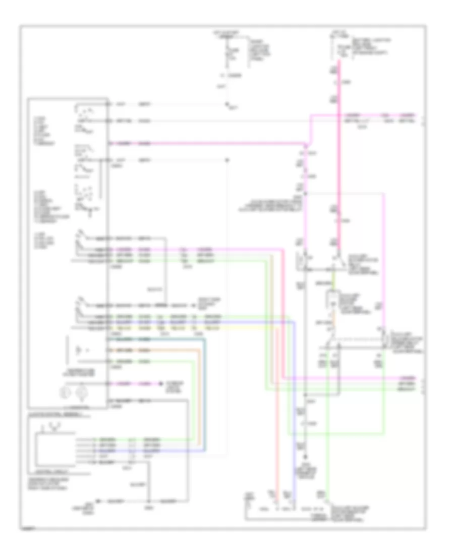
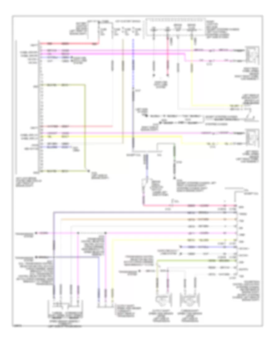
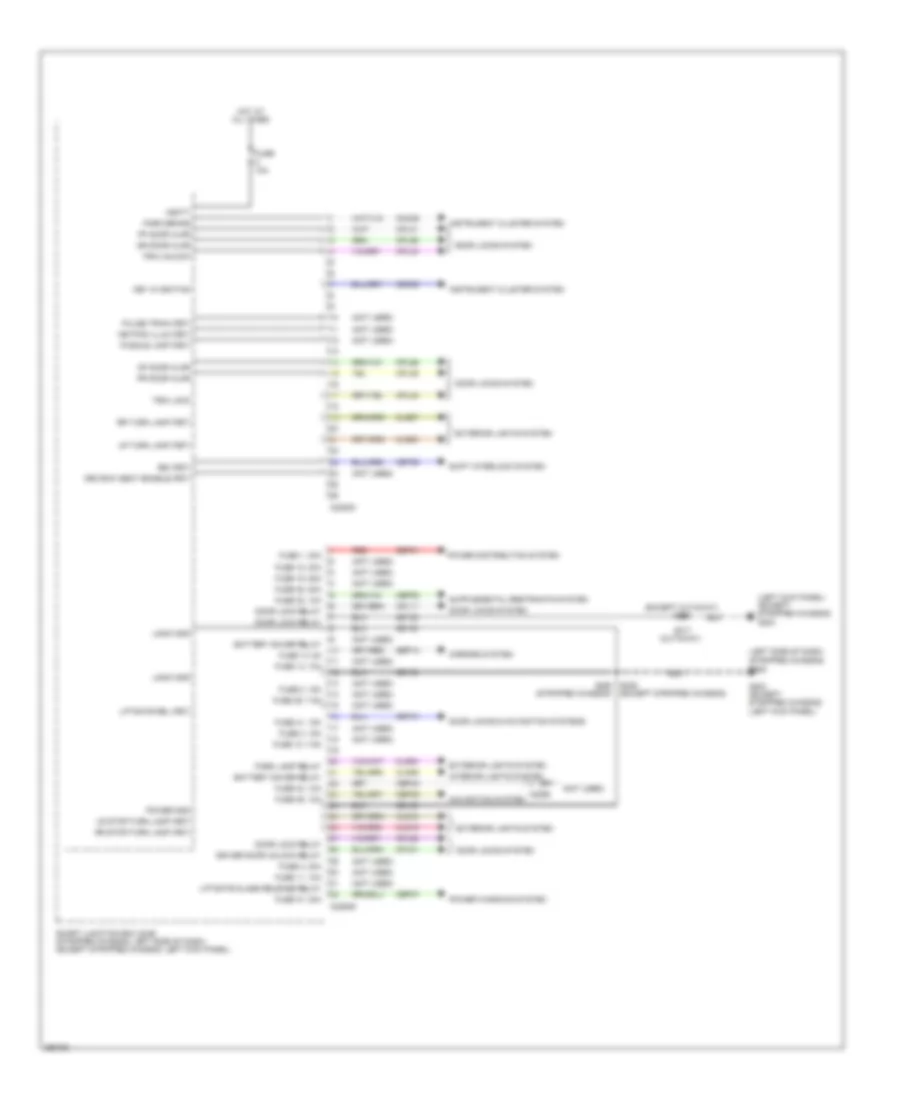
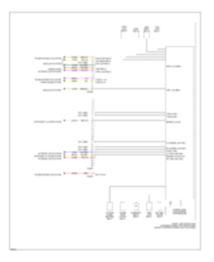
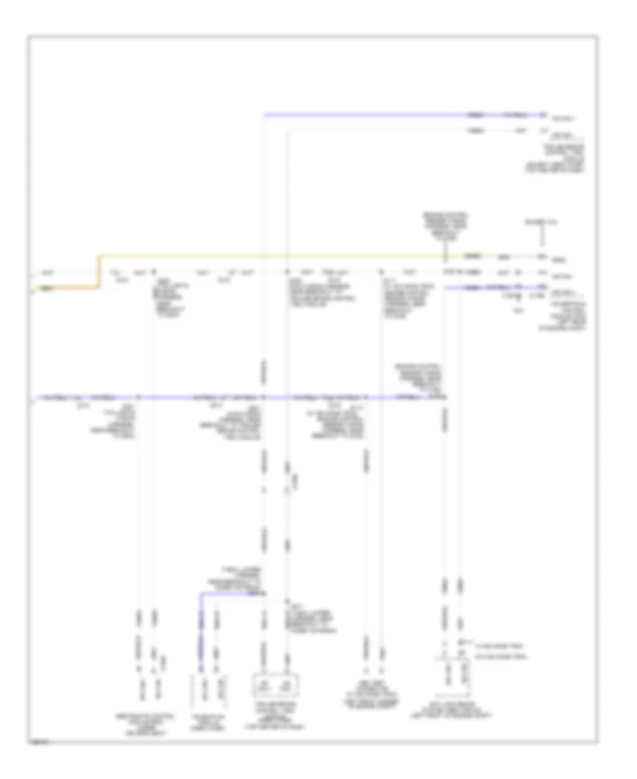
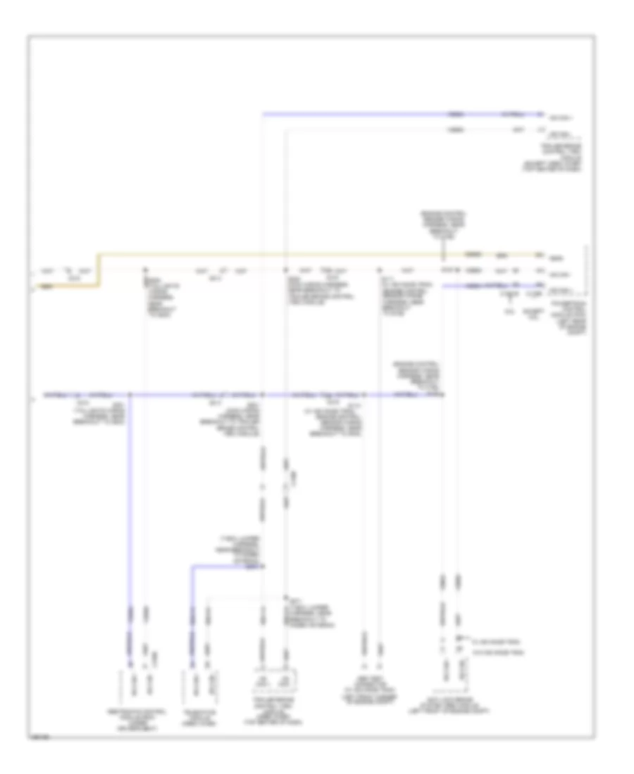
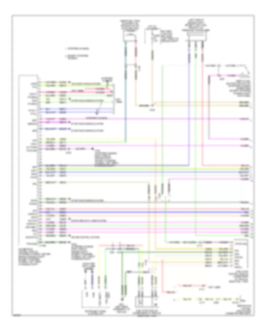
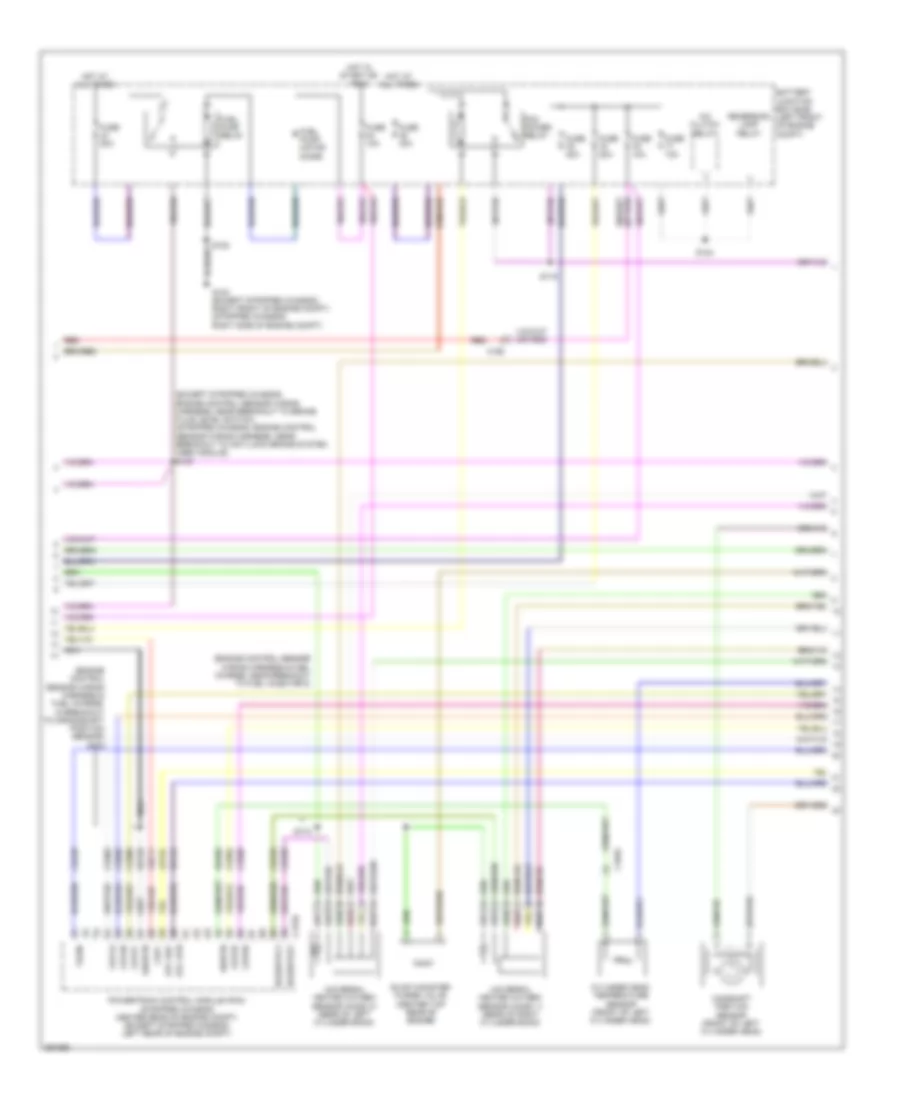
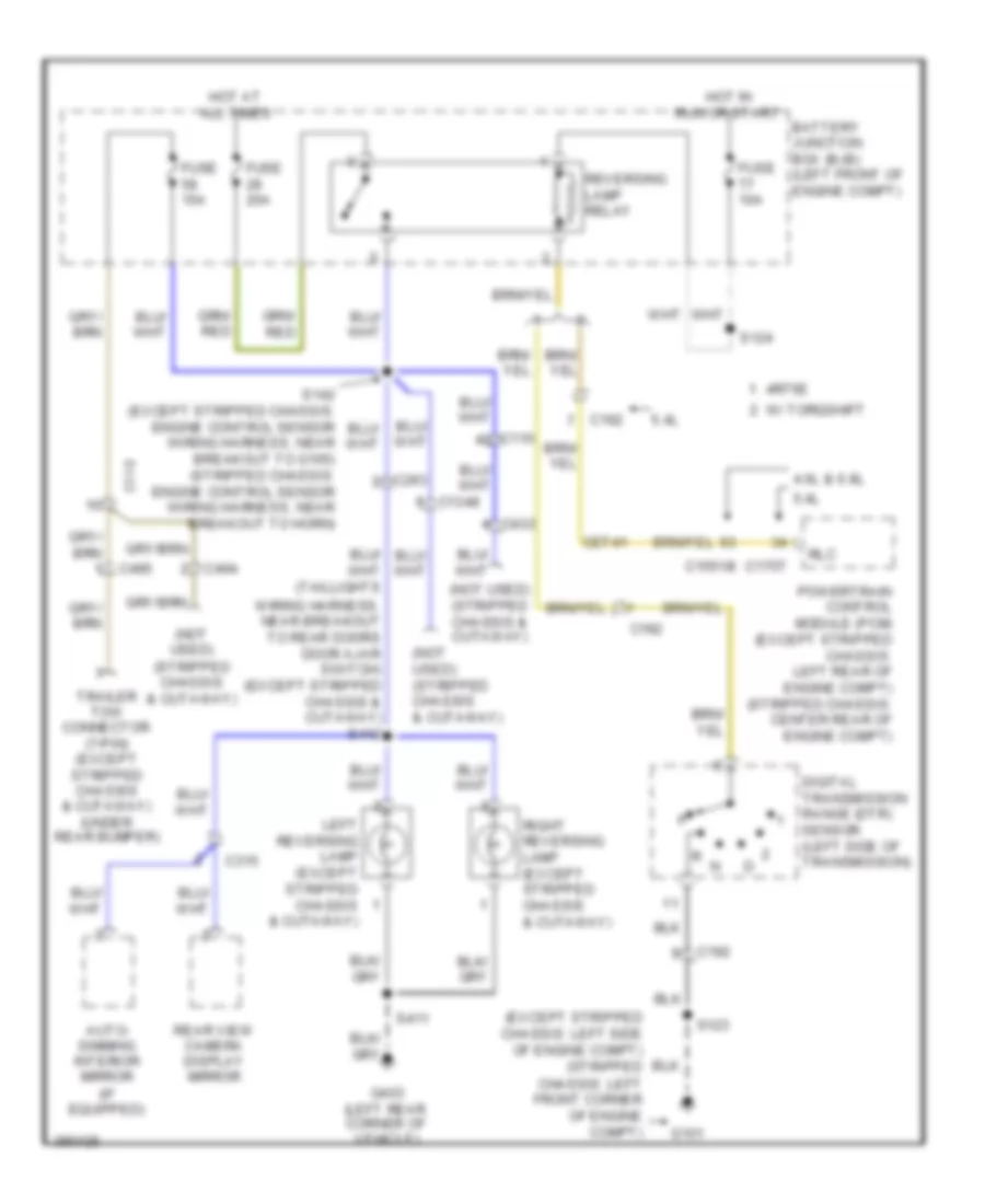
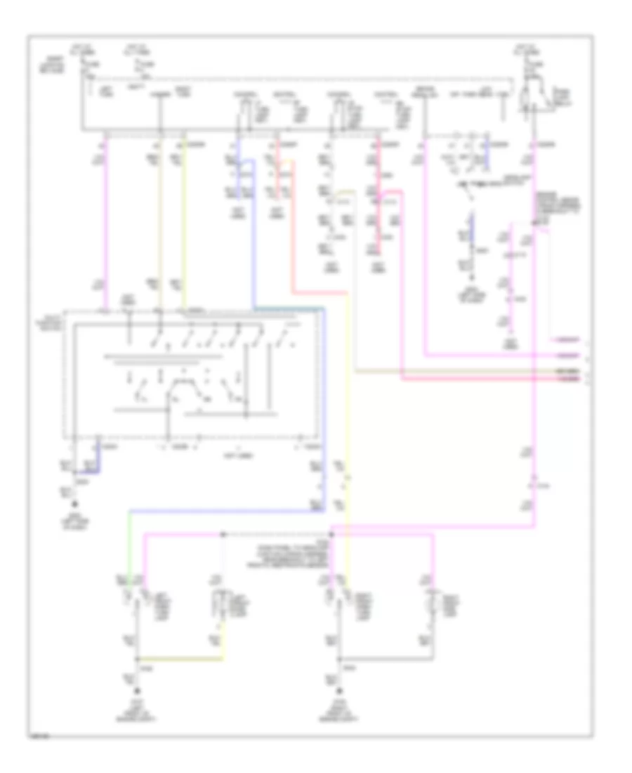
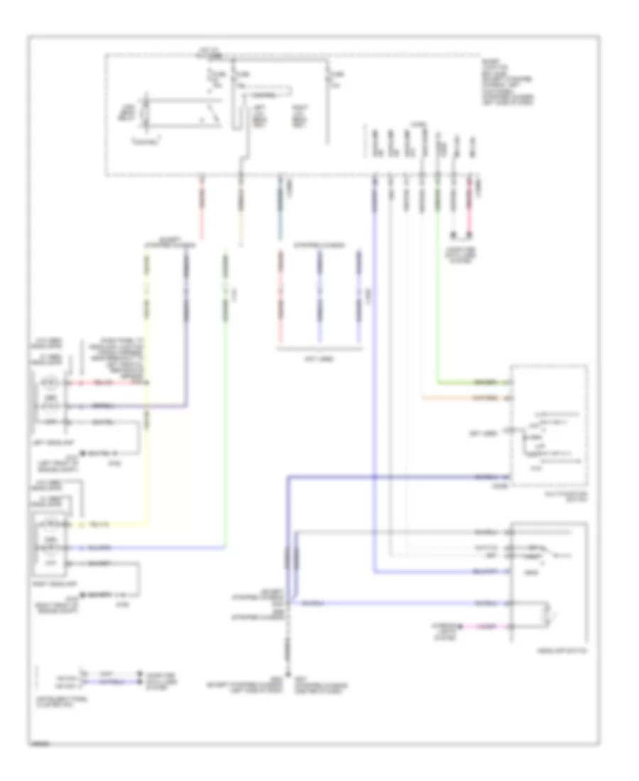
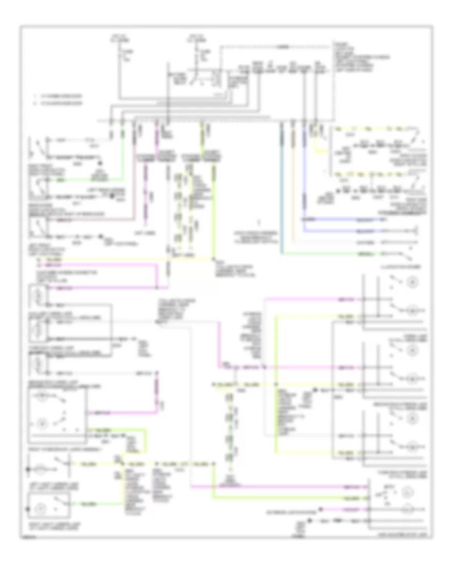
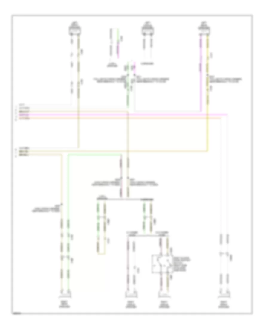
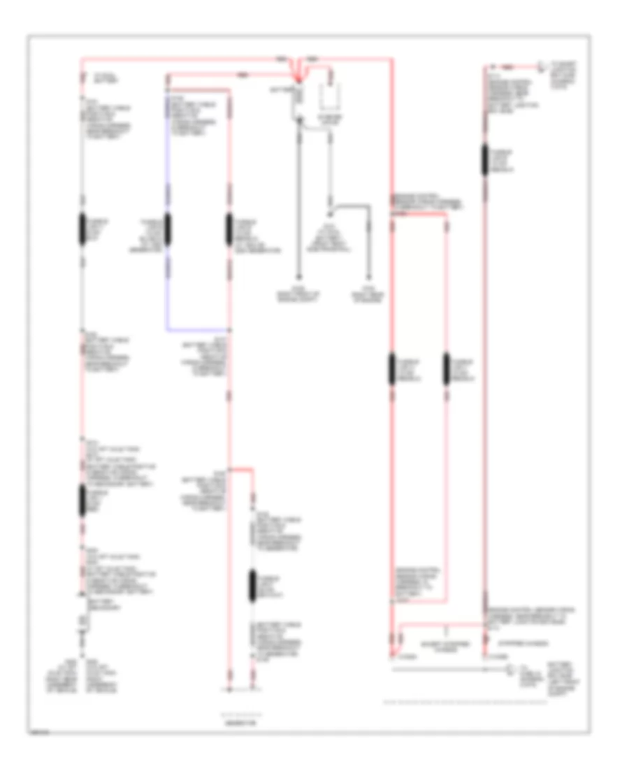
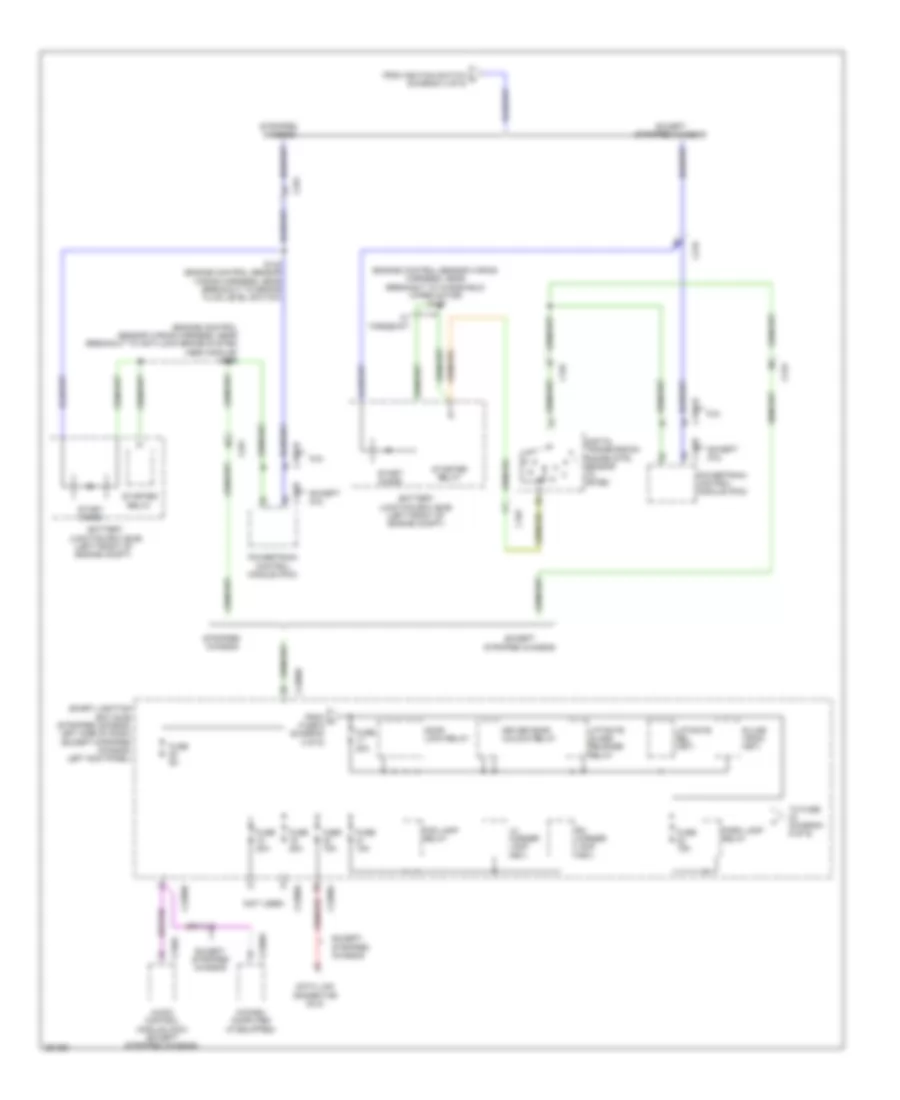
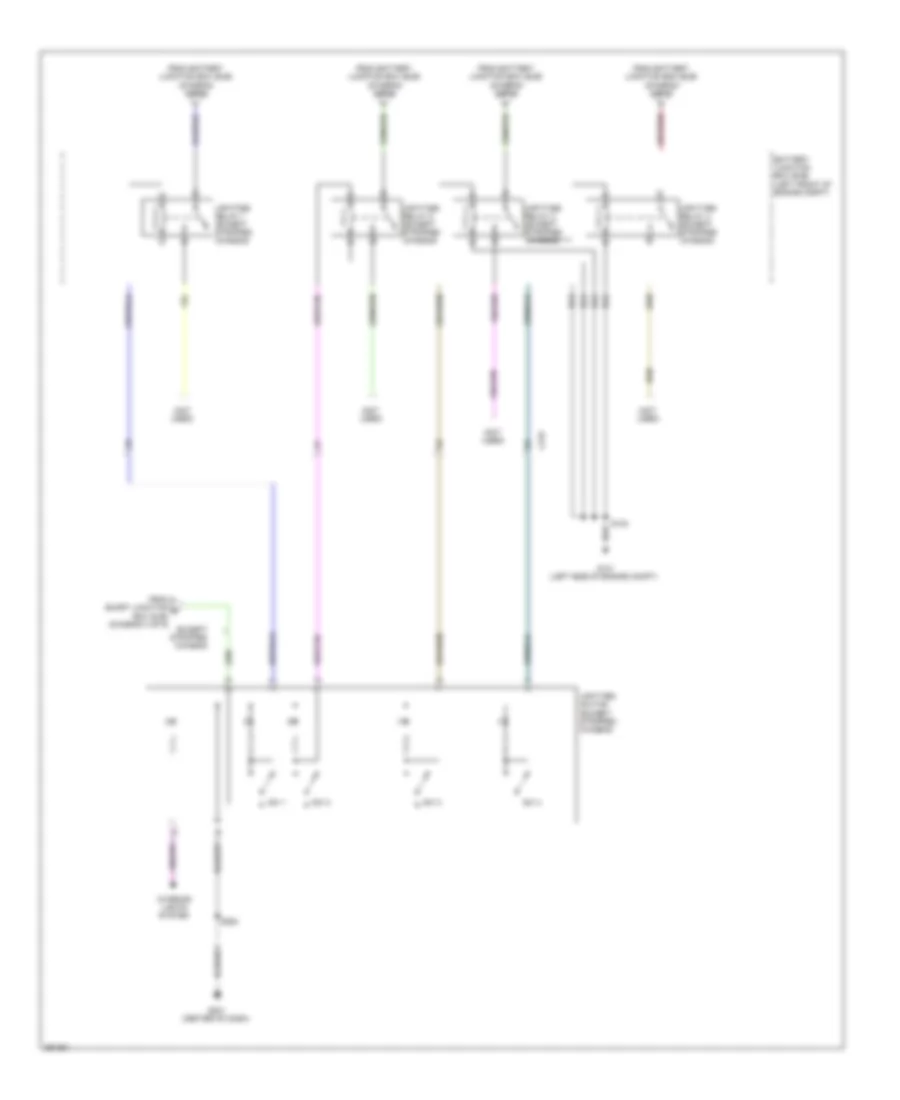
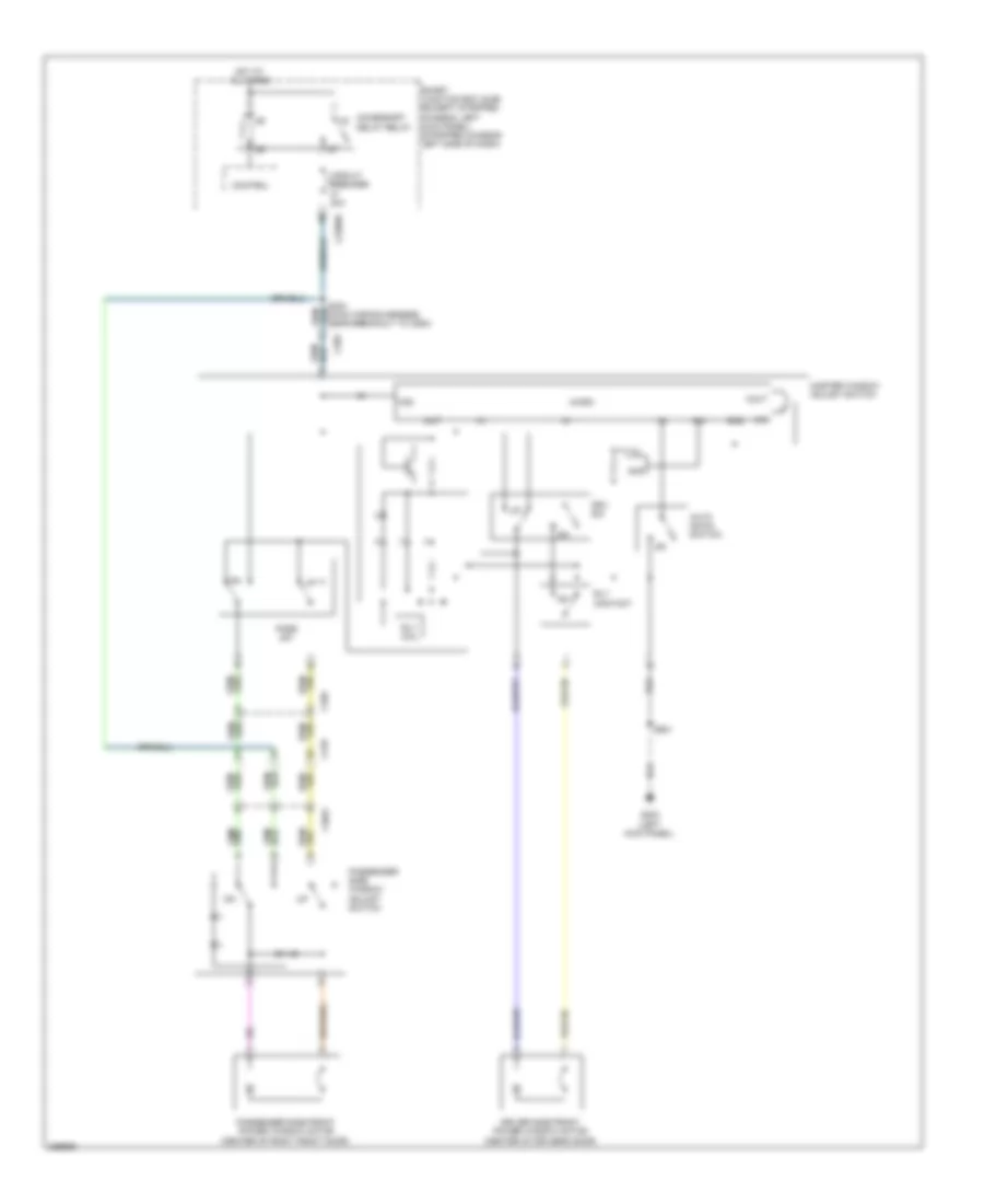
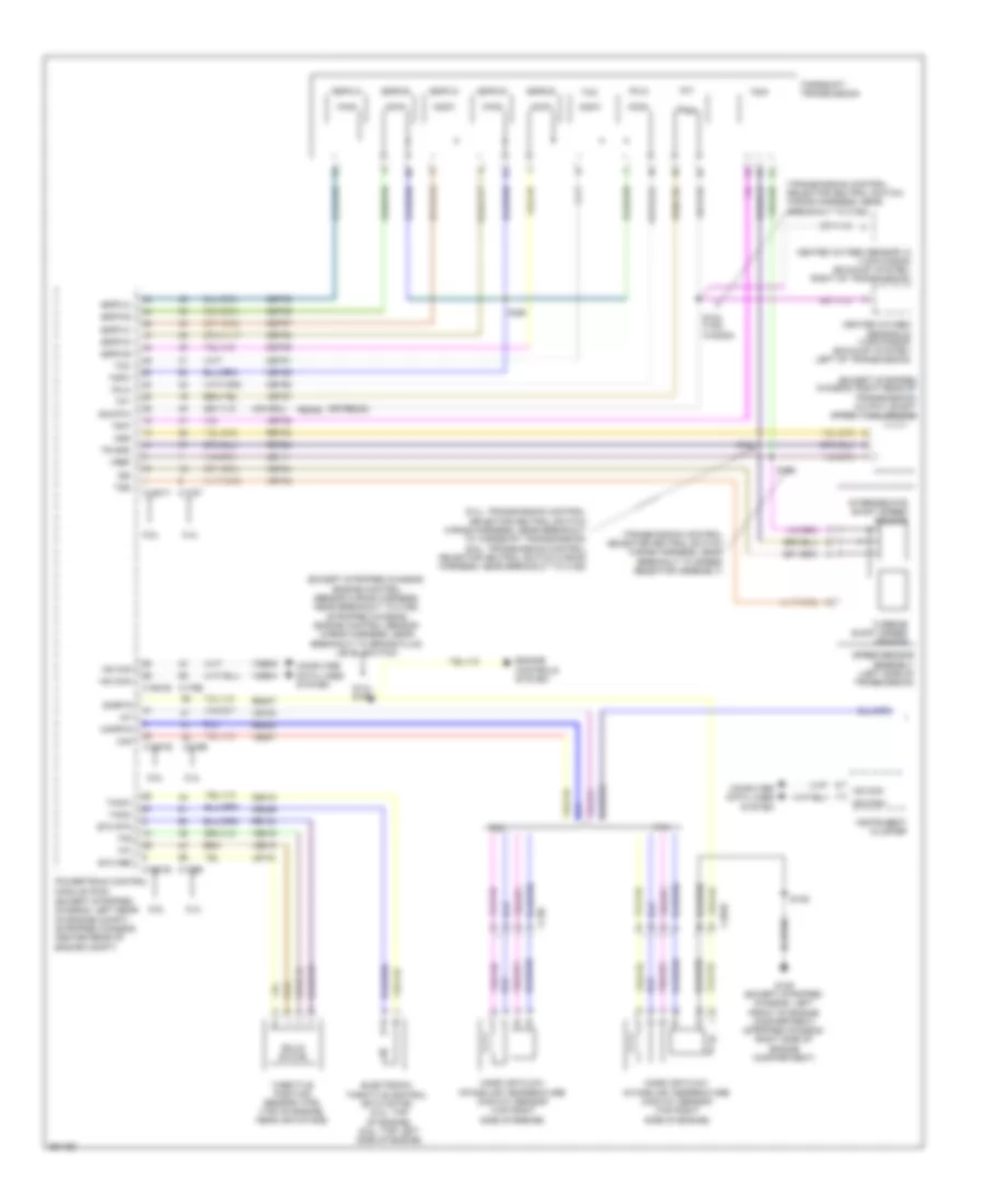
AIR CONDITIONING
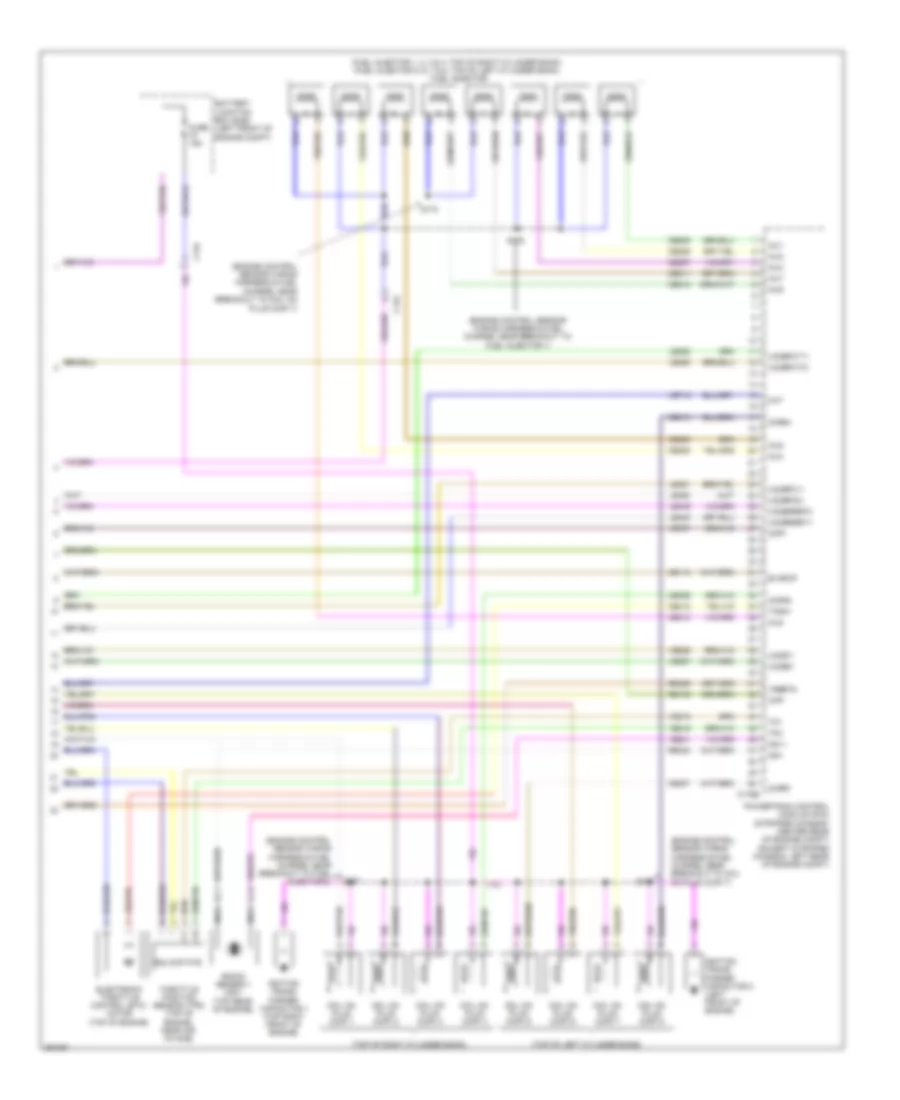
Manual A/C Wiring Diagram, with Stripped Chassis for Ford E-450 Super Duty 2013
 https://portal-diagnostov.com/license.html
Automotive Electricians Portal FZCO
Automotive Electricians Portal FZCO
https://portal-diagnostov.com/license.html
https://portal-diagnostov.com/license.html
Automotive Electricians Portal FZCO
Automotive Electricians Portal FZCO
List of elements for Manual A/C Wiring Diagram, with Stripped Chassis for Ford E-450 Super Duty 2013:
- (engine control sensor wiring harness & fuel charge, near breakout to evap canister purge valve) s172
- (not used)
- 4.6l & 5.4l
- 6.8l
- A/c clutch relay
- A/c compressor clutch field coil (lower right front of engine)
- Accr
- Accs
- Battery junction box (bjb) (left front of engine compt)
- Blower motor relay
- C1046
- C134
- C1551b
- C1551e
- C175b
- C175e
- C2095
- C291
- Ce302
- Ch302
- Ch421
- Cht
- Customer access (right front of engine compt)
- Cylinder head temperature sensor (front of left cylinder head)
- Engine controls system
- Except 5.4l
- Fuse 10a
- Fuse 40a
- Fuse 50a
- G100 (right side of engine compt)
- G101 (left front corner of engine compt)
- Hot at all times
- Pcm power relay
- Pcmrc
- Powertrain control module (pcm) (center rear of engine compt)
- Re405
- S108
- S116
- S123
- S124
- S129
- Sigrtn
- Ve712
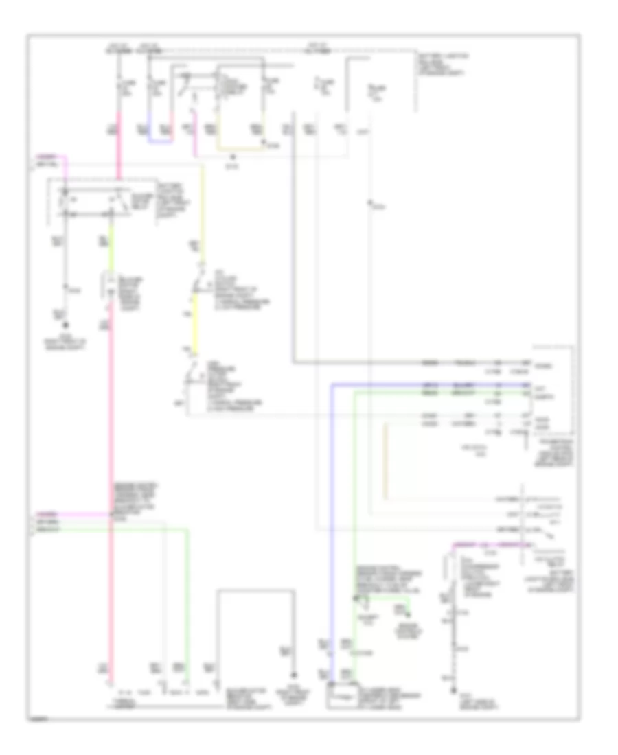
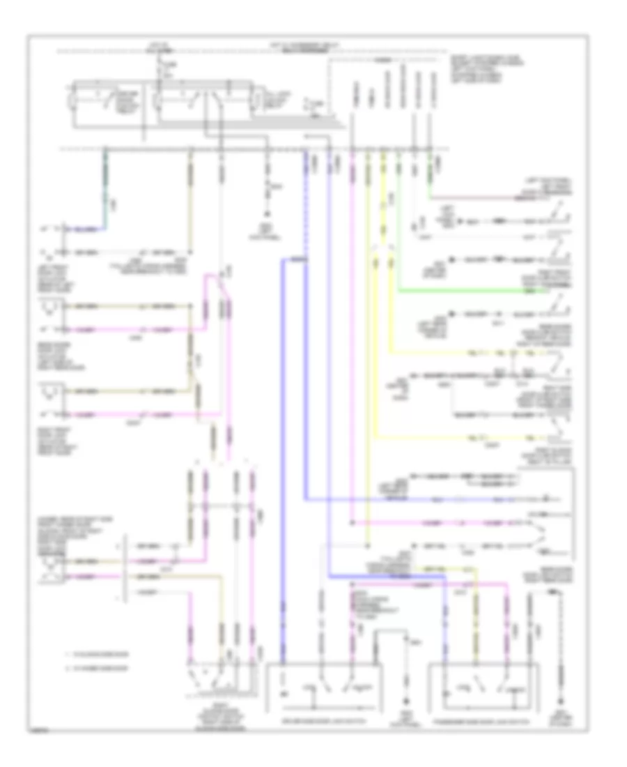
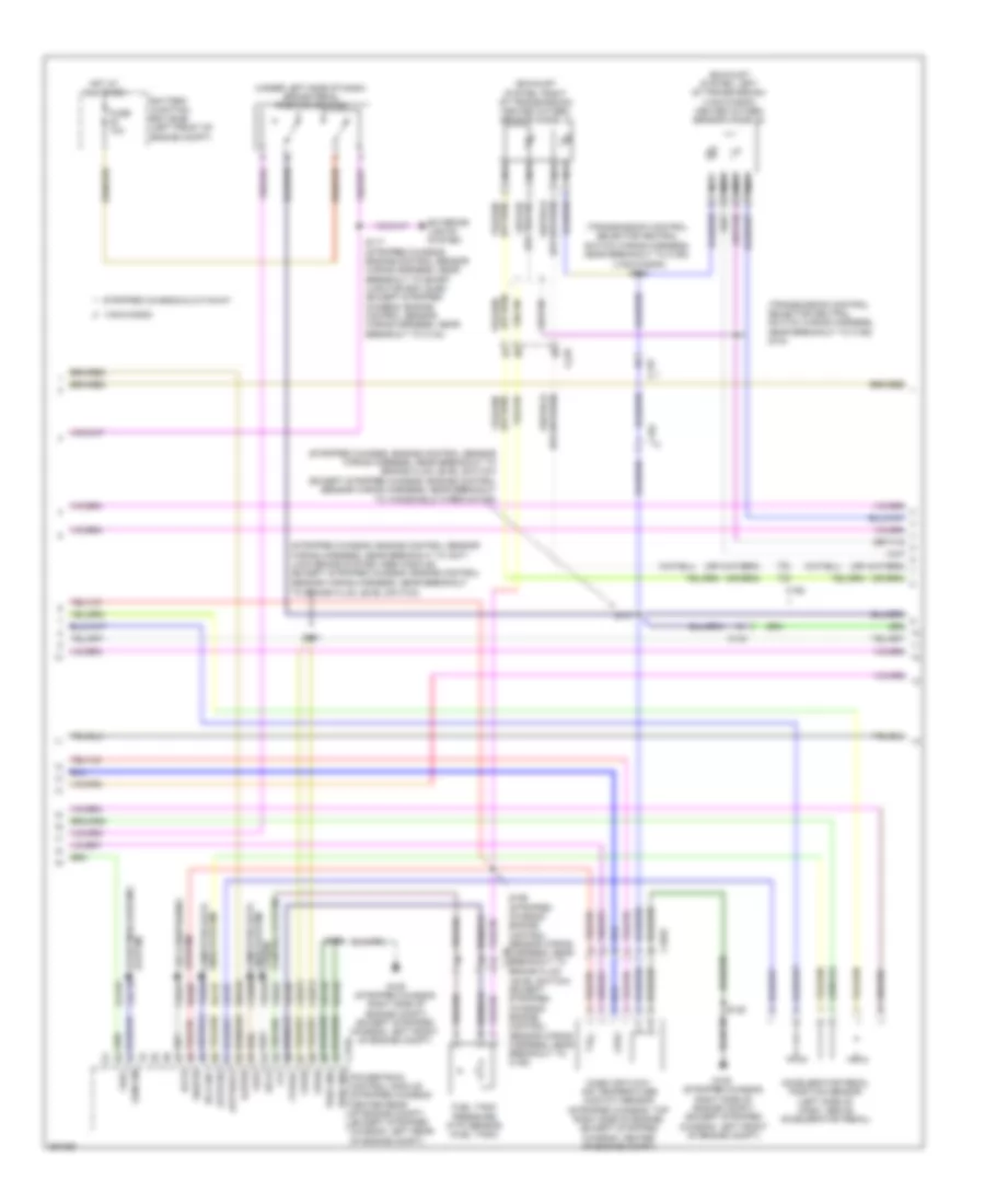
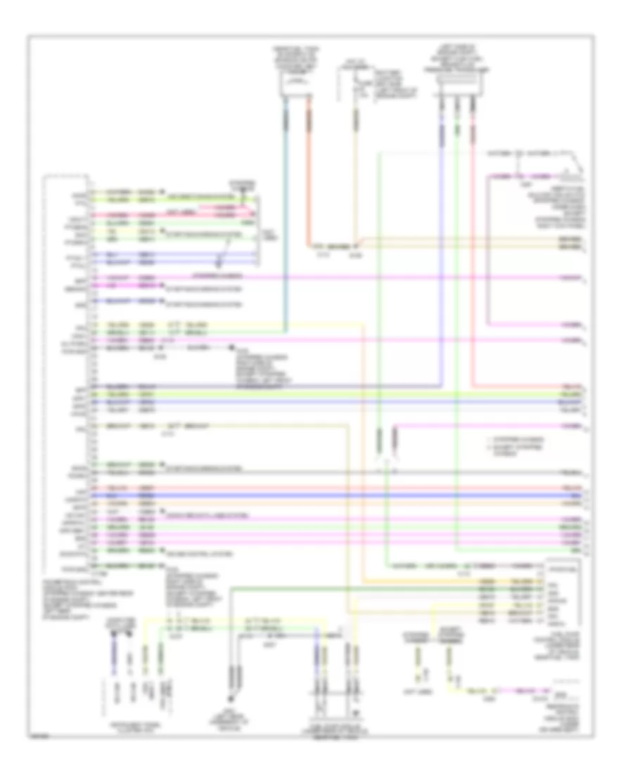
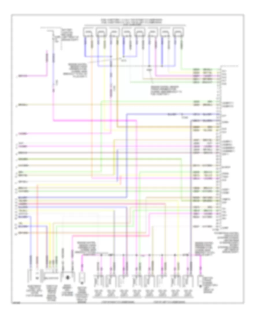
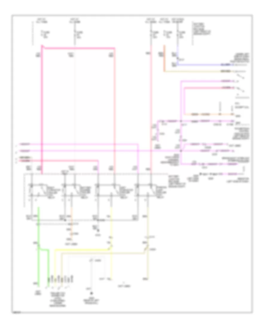
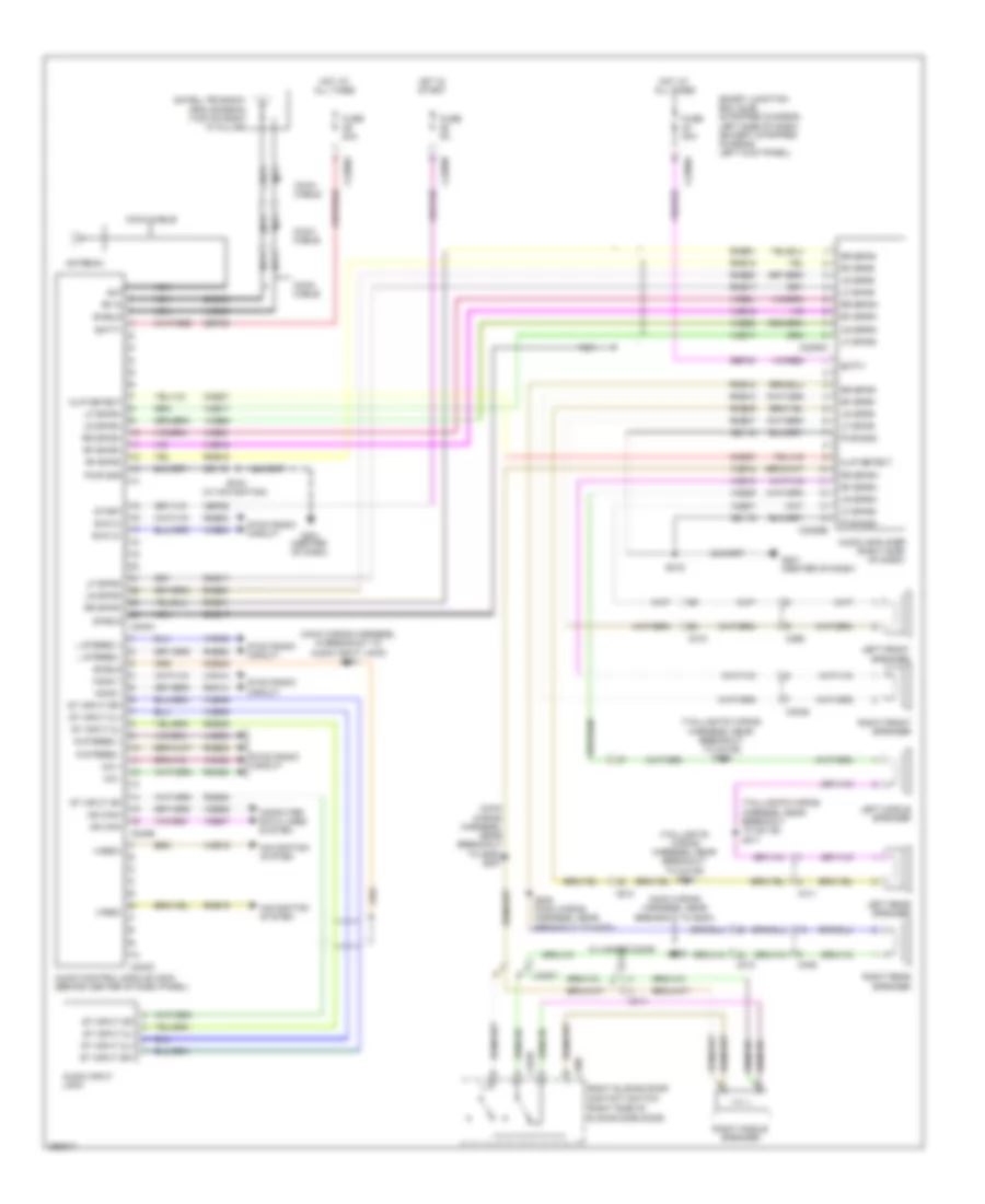
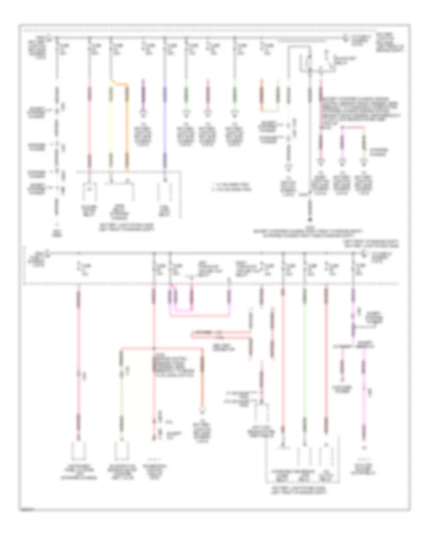
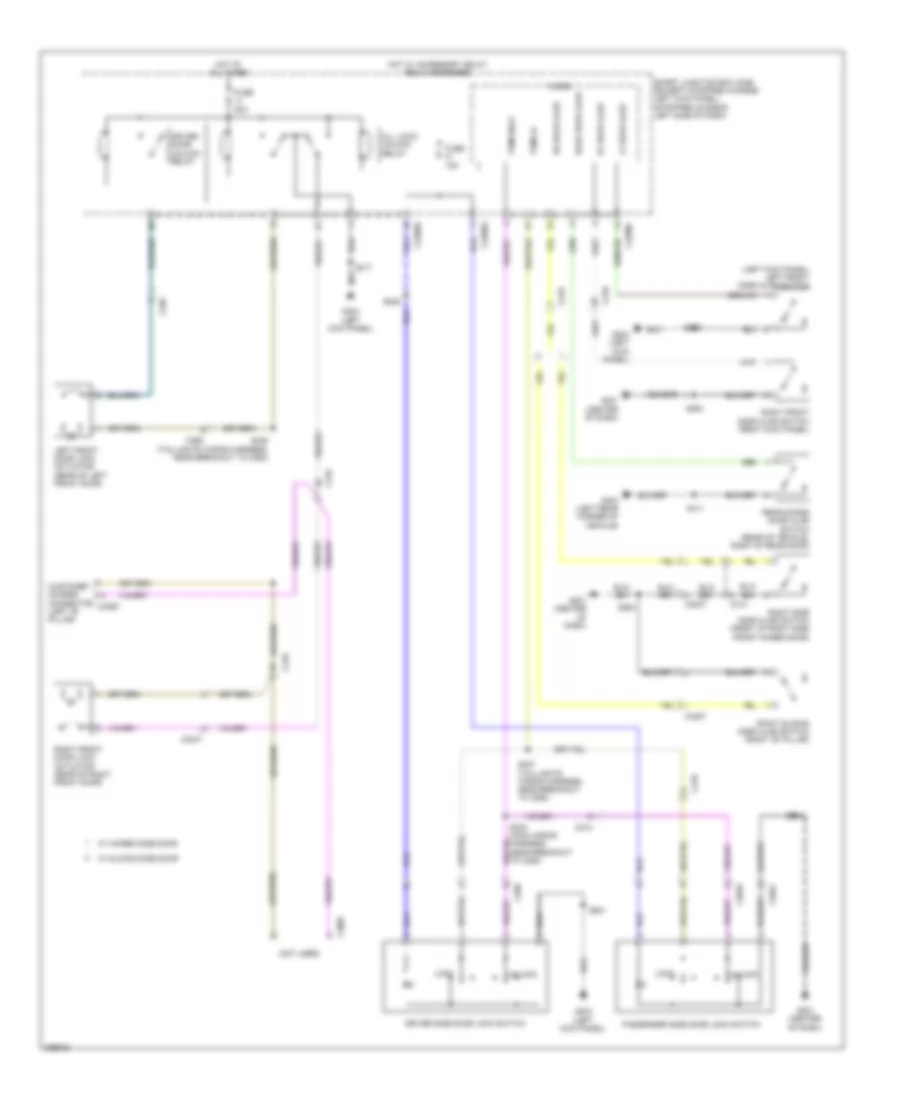
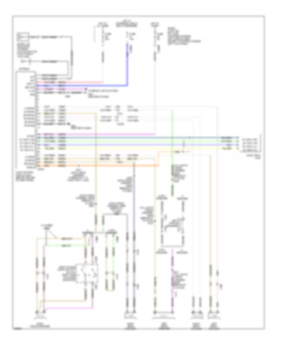
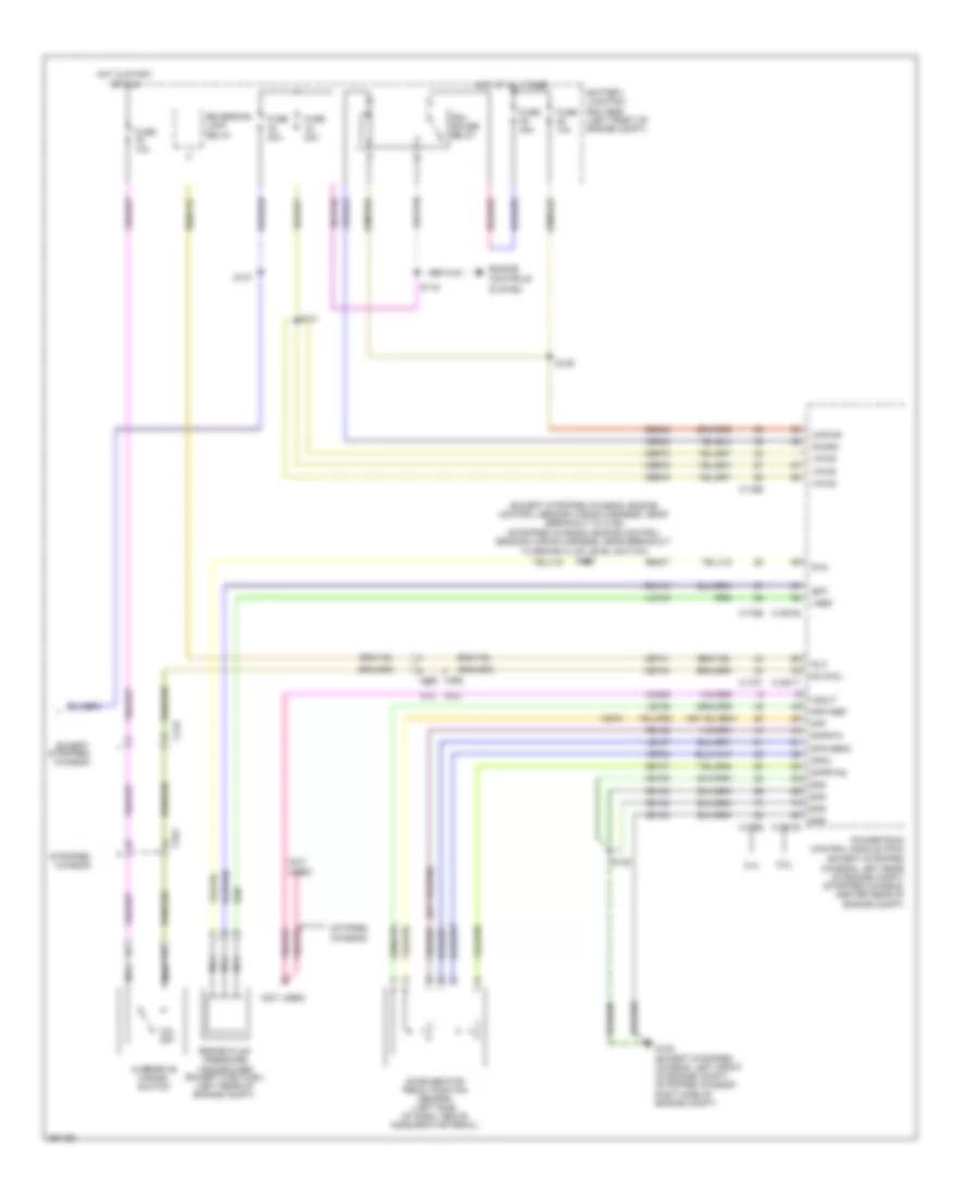
Manual A/C Wiring Diagram, without Stripped Chassis (1 of 2) for Ford E-450 Super Duty 2013
List of elements for Manual A/C Wiring Diagram, without Stripped Chassis (1 of 2) for Ford E-450 Super Duty 2013:
- (not used)
- (right side of dash) g200
- 0) off 5) max 6) normal 7) vent 8) floor/vent 9) floor 10) defrost/floor 11) defrost
- 1) max 2) a/c 3) vent 4) off 5) floor 6) mix 7) defrost
- 1) off 2) mid low 3) mid high 4) high
- 87a
- Auxiliary blower motor (left rear quarterpanel)
- Auxiliary blower motor relay (left rear quarterpanel)
- Auxiliary blower motor resistor (left rear quarterpanel)
- Auxiliary blower motor speed relay (left rear quarterpanel)
- Battery junction box (bjb) (left front of engine compt)
- C210
- C214
- C219
- C2280b
- C264
- C294a
- C294b
- C294c
- C294d
- C294e
- C405
- Cbp37
- Ch202
- Ch203
- Ch204
- Ch428
- Ch429
- Ch430
- Ch434
- Ch435
- Cha06
- Cha07
- Cha08
- Climate control assembly
- Control circuit
- Fuse 10a
- Fuse 50a
- G201 (center of dash)
- G403 (left rear corner of vehicle)
- Gd115
- Gd116
- Gnd
- High
- Hot at all times
- Hot in start or run
- Illumination
- Interior lights system
- Mid high
- Mid low
- S217
- S264
- S265
- S400 (a/c blower motor wiring harness, near breakout to auxiliary blower motor relay)
- S401
- Smart junction box (sjb) (left kick panel)
- Temperature blend door actuator (right side of dash)
- Temperature potentiometer
- Thermal limiter
- Vlno4
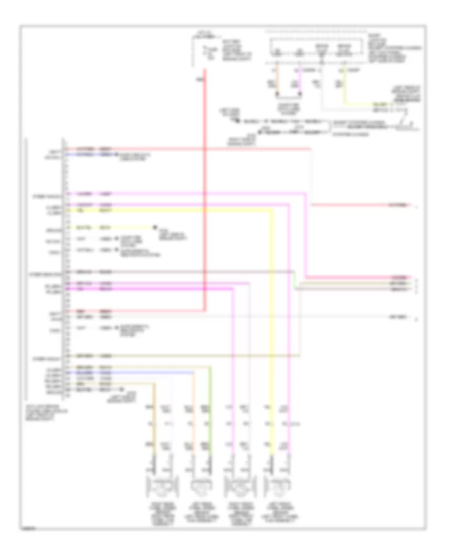
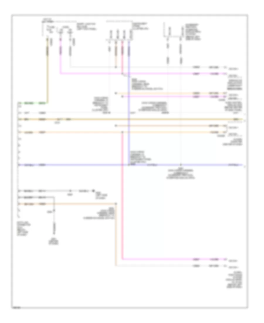
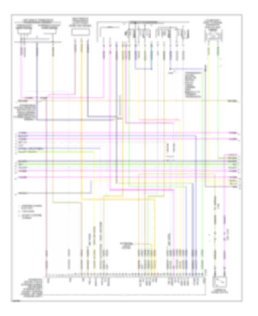
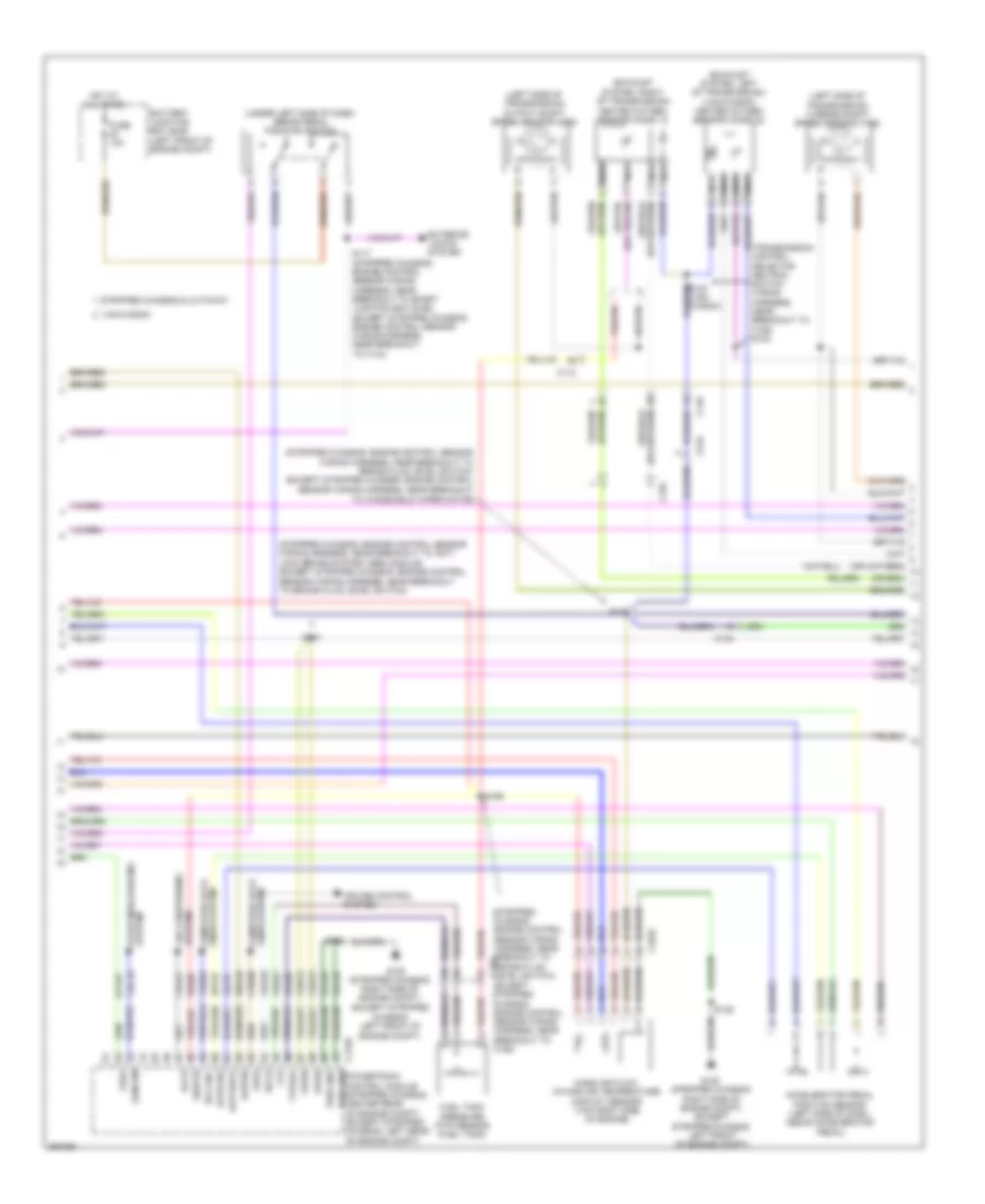
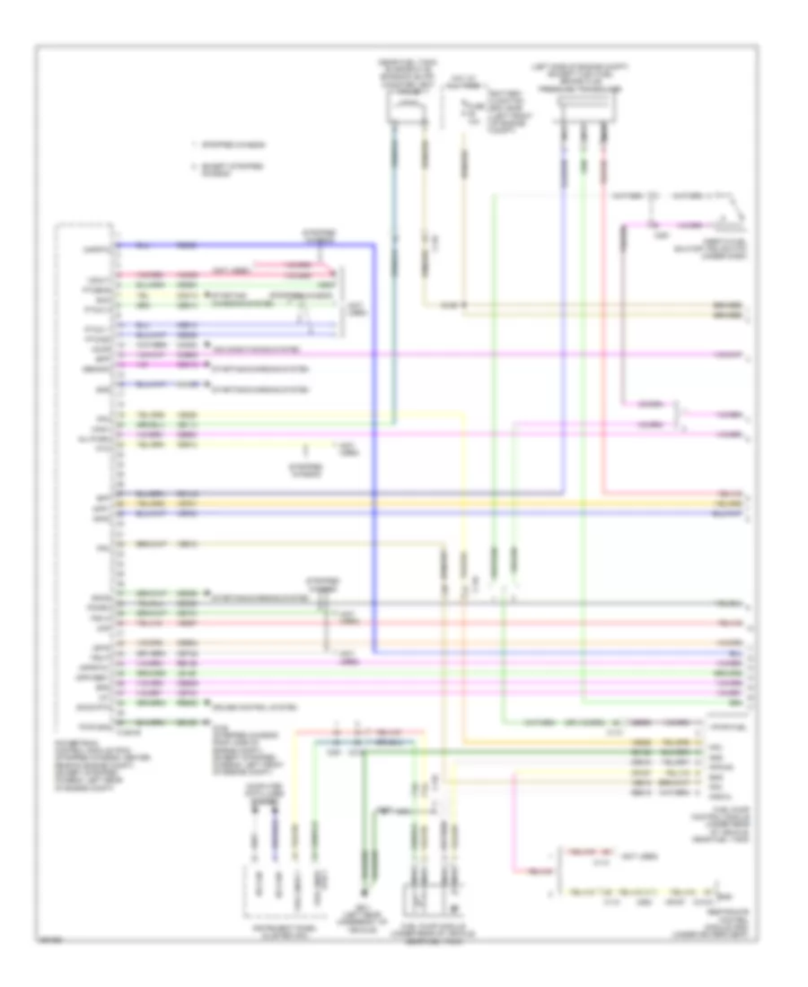
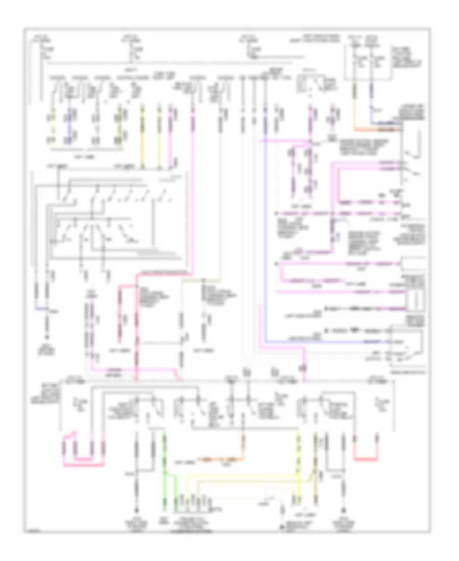
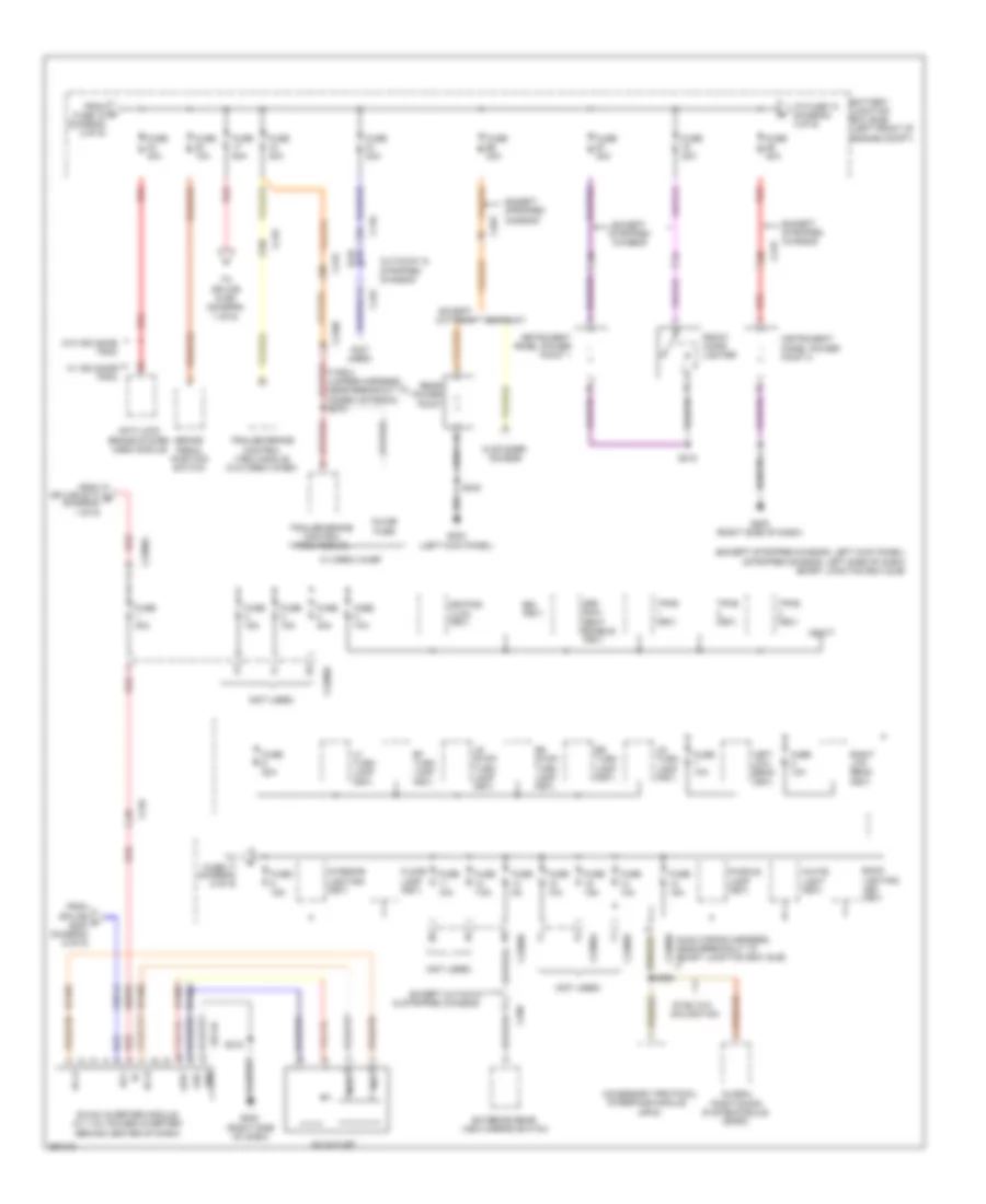
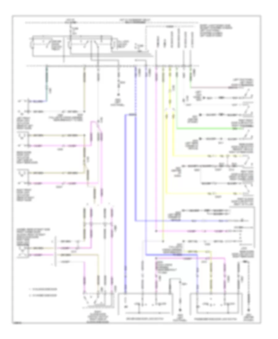
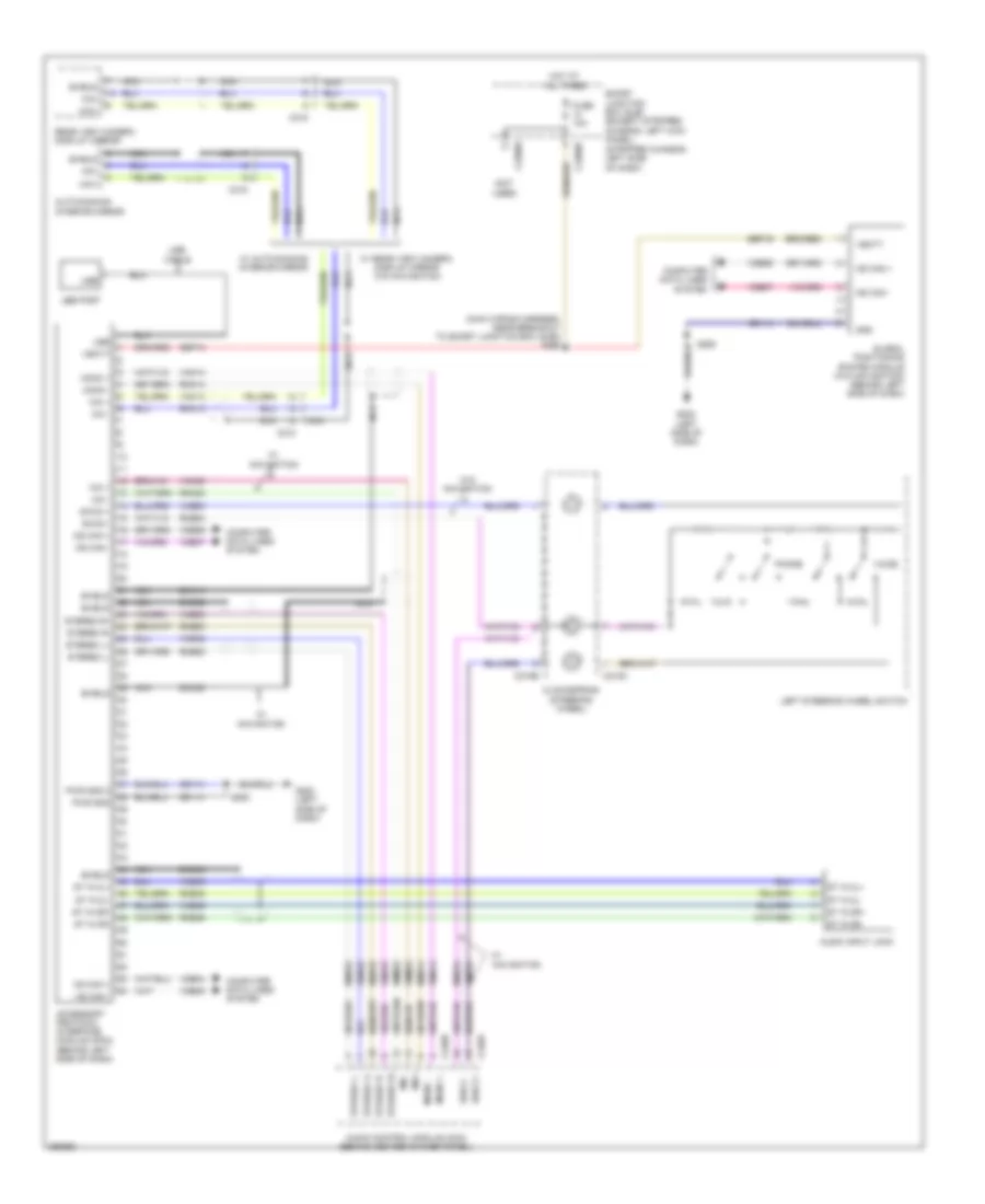
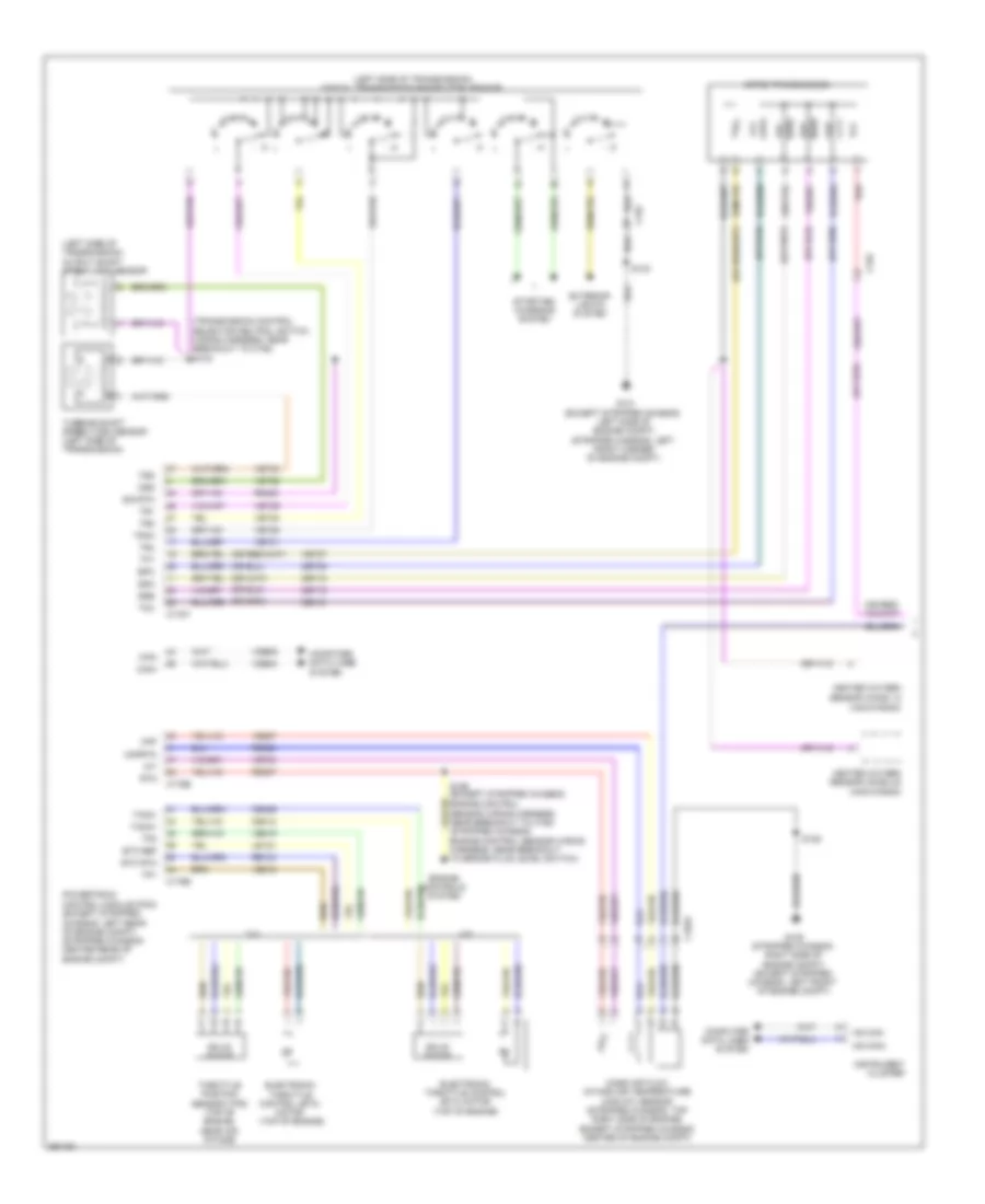
Manual A/C Wiring Diagram, without Stripped Chassis (2 of 2) for Ford E-450 Super Duty 2013
List of elements for Manual A/C Wiring Diagram, without Stripped Chassis (2 of 2) for Ford E-450 Super Duty 2013:
- (engine control sensor wiring harness & fuel charge, near breakout to evap canister purge valve) s172
- (engine control sensor wiring harness, near breakout to blower motor resistor)
- (right front of engine compt)
- 1) normal pressure 2) high pressure
- 1) normal pressure 2) low pressure
- 4.6l & 5.4l
- 6.8l
- A/c clutch relay
- A/c compressor clutch field coil (lower right front of engine)
- A/c cycling switch
- Accr
- Accs
- Battery junction box (bjb) (left front
- Battery junction box (bjb) (left front of engine compt)
- Blower motor (right side of engine compt)
- Blower motor relay
- Blower motor resistor (right side of engine compt)
- C1046
- C134
- C1551b
- C175b
- C175e
- Ce302
- Ch302
- Ch421
- Cht
- Compt)
- Cylinder head temperature sensor (front of left cylinder head)
- Engine controls system
- Except 5.4l
- Fuse 10a
- Fuse 40a
- Fuse 50a
- G100 (right front of engine compt)
- G101 (left side of engine compt)
- High pressure cutoff
- Hot at all times
- Of engine
- Pcm power relay
- Pcmrc
- Powertrain control module (pcm) (left rear of engine compt)
- Re405
- S105
- S108
- S116
- S123
- S124
- S129
- Sigrtn
- Switch (right front of engine compt)
- Thermal limiter
- Ve712
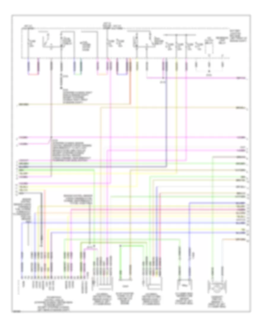
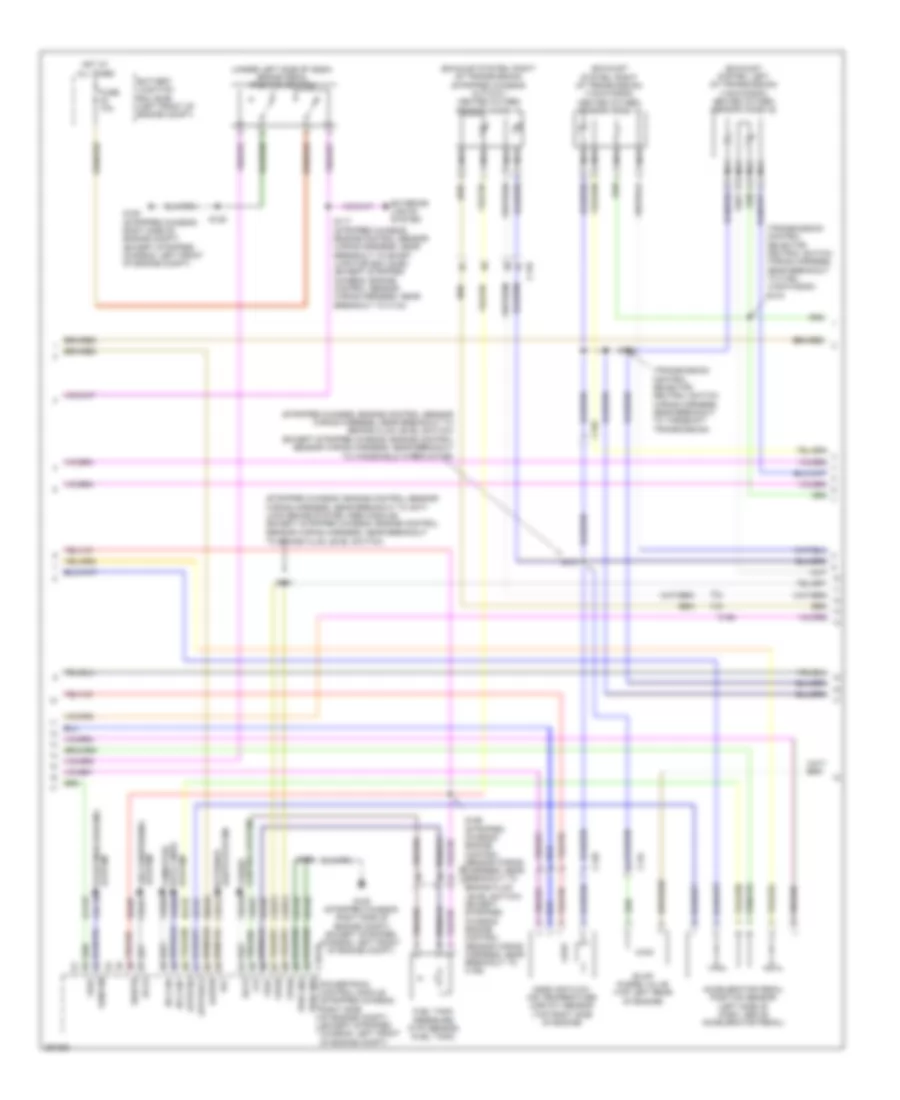
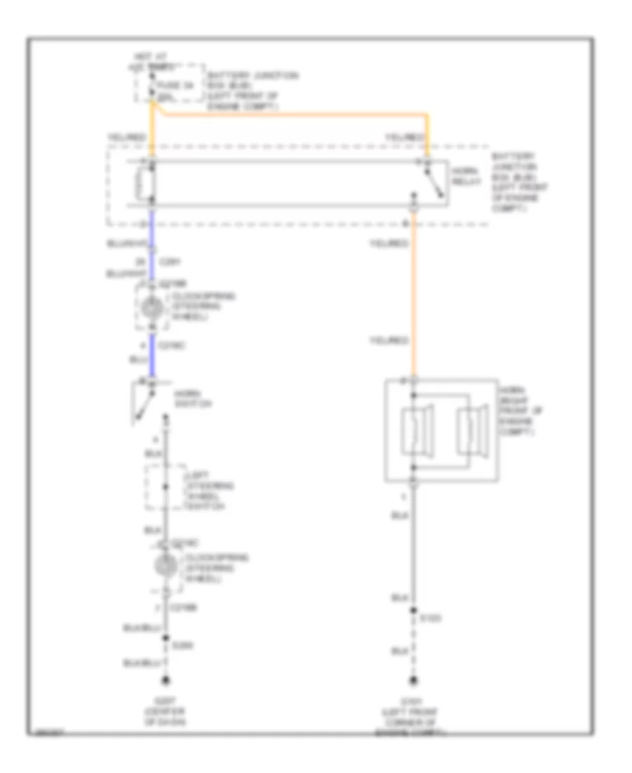
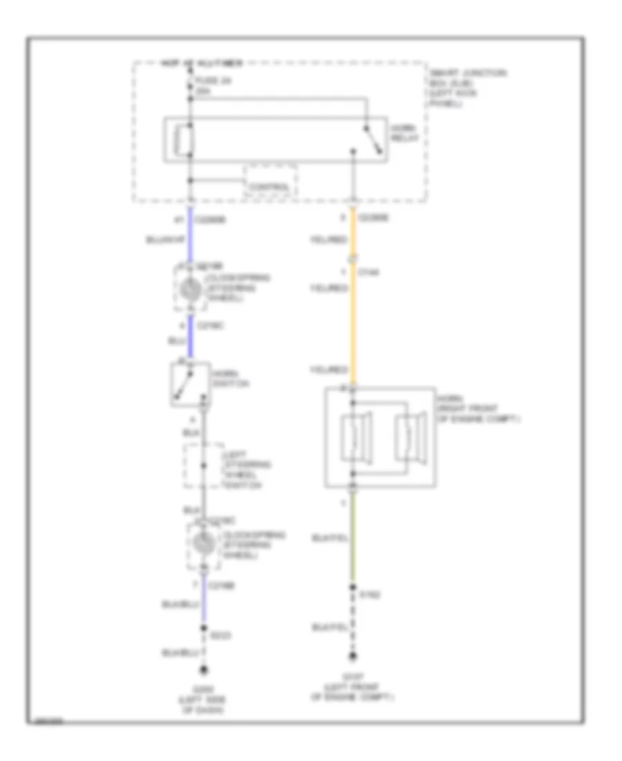
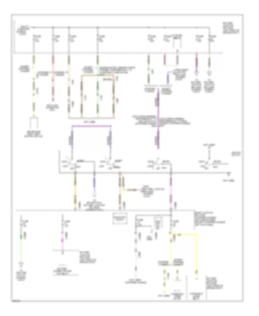
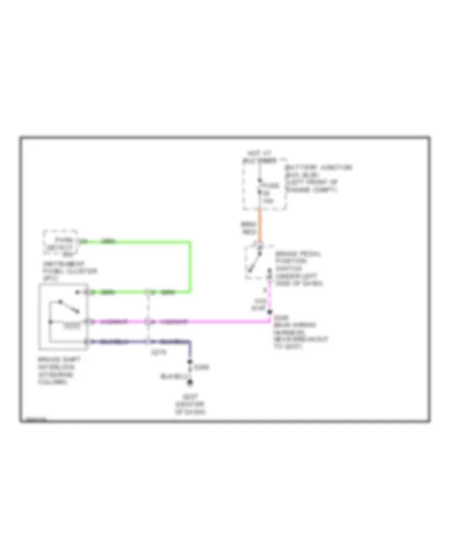
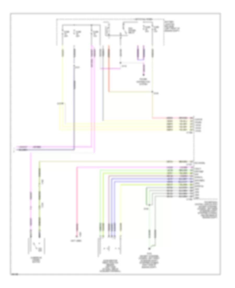
ANTI-LOCK BRAKES
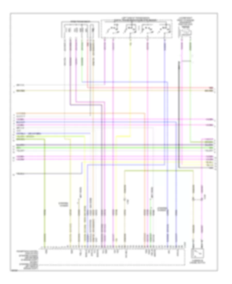
Anti-lock Brakes Wiring Diagram, with Stability Assist (1 of 2) for Ford E-450 Super Duty 2013
List of elements for Anti-lock Brakes Wiring Diagram, with Stability Assist (1 of 2) for Ford E-450 Super Duty 2013:
- (left rear of engine compt) brake fluid level switch
- (left side of dash)
- Anti-lock brake system (abs) module (left front of engine compt)
- Battery junction box (bjb) (left front of engine compt)
- Brake fluid sw
- Brake fluid sw rtn
- C110
- C219
- C2280b
- C2280f
- Can2 +
- Can2 -
- Cbb53
- Computer data lines system
- Except stripped chassis
- Fuse 40a
- G100 (right side of engine compt)
- G102 (left side of engine compt)
- G202
- Gd121
- Ground
- Hot at all times
- Hs can +
- Hs can -
- Left front wheel speed sensor (left front wheel hub assembly)
- Left rear wheel speed sensor (left rear wheel hub assembly)
- Lf_sen+
- Lf_sen-
- Lr_sen+
- Lr_sen-
- Ms can+
- Ms can-
- Nca
- Rca09
- Rca17
- Rca18
- Rca19
- Rca20
- Red
- Rf_sen+
- Rf_sen-
- Right front wheel speed sensor (right front wheel hub assembly)
- Right rear wheel speed sensor (right rear wheel hub assembly)
- Rr_sen+
- Rr_sen-
- S108
- S223
- Sbb33
- Sbb47
- Smart junction box (sjb) (except stripped chassis: left kick panel) (stripped chassis: left side of dash)
- Steer angle 1
- Steer angle 2
- Steer sens gnd
- Stripped chassis
- Vbatt
- Vca03
- Vca04
- Vca05
- Vca06
- Vcs06
- Vcs07
- Vdb04
- Vdb05
- Vpwr
Anti-lock Brakes Wiring Diagram, with Stability Assist (2 of 2) for Ford E-450 Super Duty 2013
List of elements for Anti-lock Brakes Wiring Diagram, with Stability Assist (2 of 2) for Ford E-450 Super Duty 2013:
- (left front of engine compt)
- (left side of dash) (stripped chassis) g205
- (not used)
- (stripped chassis) s250
- (transmission control selector neutral switch wiring harness, near breakout to c192)
- 6.8l
- Abs test connector (left front corner of engine compt)
- Battery junction box (bjb)
- Bps
- Brake pedal position switch (under left side of dash)
- C134
- C1551b
- C1551t
- C175b
- C175t
- C219
- Cbb53
- Ces09
- Computer data lines system
- Except 6.8l
- Fuse 10a
- Fuse 20a
- Fuse 40a
- G103 (left side of engine compt)
- G105 (except stripped chassis: left front of engine compt) (stripped chassis: right side of engine compt)
- G201 (except stripped chassis) (center of dash)
- Gd121
- Hot at all times
- Hot in start or run
- Hs can +
- Hs can -
- Hs can+
- Hs can-
- Instrument panel cluster (ic)
- Interior lights system
- Intermediate shaft speed sensor
- Iss
- Le111
- Oss
- Output shaft speed (oss) sensor (4r75e) (left side of transmission)
- Output shaft speed (oss) sensor (torqshift) (right rear of transmission)
- Powertrain control module (pcm) (stripped chassis: center rear of engine compt) (except stripped chassis: left rear of engine compt)
- Re406
- Ret04
- Ret24
- S101 (6.8l: transmission control selector neutral switch wiring harness, near breakout to c192) (5.4l: transmission control selector neutral switch wiring harness, near breakout to torqshift transmission)
- S102 (transmission control selector neutral switch wiring harness, speed selector assembly)
- S104
- S125
- S137
- S264 (except stripped chassis)
- Sbb47
- Sig rtn
- Solid state
- Speed sensor assembly (torqshift) (left side of transmission)
- Steering position sensor (bottom of steering column)
- Tc on/off
- Traction control switch
- Transmissions system
- Trgnd
- Tss
- Turbine shaft speed (tss) sensor (4r75e) (left side of transmission)
- Turbine shaft speed sensor
- Vdb04
- Vdb05
- Ve744
- Vet26
- Vet33
- Vref
Anti-lock Brakes Wiring Diagram, without Stability Assist for Ford E-450 Super Duty 2013
List of elements for Anti-lock Brakes Wiring Diagram, without Stability Assist for Ford E-450 Super Duty 2013:
- (left rear of engine compt) brake fluid level switch
- (left side of dash)
- (not used)
- (transmission control selector neutral switch wiring harness,
- 6.8l
- Abs active
- Anti-lock brake system (abs) module (left front of engine compt)
- Battery junction box (bjb) (left front of engine compt)
- Bps
- Brake fluid sw
- Brake fluid sw rtn
- Brake pedal position switch (under left side of dash)
- C110
- C134
- C1551b
- C1551t
- C175b
- C175t
- C219
- C2280b
- C2280f
- Cbb53
- Cca01
- Ces09
- Computer data lines system
- Except 6.8l
- Except stripped chassis
- Fuse 10a
- Fuse 20a
- Fuse 40a
- G100 (right side of engine compt)
- G102 (left side of engine compt)
- G105 (except stripped chassis: left front of engine compt) (stripped chassis: right side of engine compt)
- G202
- Gd121
- Gnd
- Hot at all times
- Hot in start or run
- Hs can +
- Hs can -
- Intermediate shaft speed sensor
- Iss
- Le111
- Left front wheel speed sensor (left front wheel hub assembly)
- Ms can+
- Ms can-
- Nca
- Near breakout to c192)
- Oss
- Output shaft speed (oss) sensor (4r75e) (left side of transmission)
- Output shaft speed (oss) sensor (torqshift) (right rear of transmission)
- Powertrain control module (pcm) (stripped chassis: center rear of engine compt) (except stripped chassis: left rear of engine compt)
- Rca17
- Rca19
- Re406
- Red
- Ret04
- Ret24
- Right front wheel speed sensor (right front wheel hub assembly)
- S101 (6.8l: transmission control selector neutral switch wiring harness, near breakout to c192) (5.4l: transmission control selector neutral switch wiring harness, near breakout to torqshift transmission)
- S102 (transmission control selector neutral switch wiring harness, near breakout to speed selector assembly)
- S104
- S108
- S125
- S137
- S223
- Sbb33
- Sbb47
- Sig rtn
- Smart junction box (sjb) (except stripped chassis: left kick panel) (stripped chassis: left side of dash)
- Speed sensor assembly (torqshift) (left side of transmission)
- Stripped chassis
- Transmissions system
- Trgnd
- Tss
- Turbine shaft speed (tss) sensor (4r75e) (left side of transmission)
- Turbine shaft speed sensor
- Vbatt
- Vca03
- Vca05
- Vdb04
- Vdb05
- Ve744
- Vet26
- Vet33
- Vpwr
- Vref
- Wheel spd lf+
- Wheel spd lf-
- Wheel spd rf+
- Wheel spd rf-
ANTI-THEFT
Forced Entry Wiring Diagram, with Cutaway for Ford E-450 Super Duty 2013
List of elements for Forced Entry Wiring Diagram, with Cutaway for Ford E-450 Super Duty 2013:
- (left kick panel) left front door ajar switch
- (not used)
- All lock/ unlock relay
- C210
- C2280a
- C2280c
- C2280d
- C265
- C268
- C3007
- C3047
- C3049
- C314
- C3359
- Customer access connector (left "b" pillar)
- Driver door unlock relay
- Driver side door lock switch
- Fuse 15a
- Fuse 20a
- G201 (center of dash)
- G203 (left kick panel)
- G403 (left rear corner of vehicle)
- Hot at all times
- Hot w/ accessory delay relay energized
- Left front door lock actuator (rear of left front door)
- Lf door ajar
- Lock
- Micro
- Passenger side door lock switch
- Rear door ajar
- Rear doors door ajar switch (rear of vehicle, right of rear door)
- Rf door ajar
- Right front door ajar switch (right kick panel)
- Right front door lock actuator (rear of right front door)
- Right side door ajar switch (front of right side front hinged door)
- Right sliding door ajar switch (right "b" pillar)
- Rr door ajar
- S233 (main wiring harness, near breakout to c264)
- S236
- S237 (taillights wiring harness, near breakout to c263)
- S238 (taillights wiring harness, near breakout to c263)
- S239
- S264
- S317
- S411
- S501
- Smart junction box (sjb) (except stripped chassis: left kick panel) (stripped chassis: left side of dash)
- Trim lk
- Trim unlk
- Unlock
- W/ hinged side door
- W/ sliding side door
Forced Entry Wiring Diagram, without Cutaway for Ford E-450 Super Duty 2013
List of elements for Forced Entry Wiring Diagram, without Cutaway for Ford E-450 Super Duty 2013:
- (hinged: rear of right side front hinged door) (sliding: front of right side sliding door) right side door lock actuator
- (left kick panel) g203
- (left kick panel) left front door ajar switch
- All lock/ unlock relay
- C210
- C2280a
- C2280c
- C2280d
- C265
- C268
- C3007
- C3047
- C3049
- C313
- C314
- C3235
- C406
- C807
- Driver door unlock relay
- Driver side door lock switch
- Fuse 15a
- Fuse 20a
- G201 (center of dash)
- G203 (left kick panel)
- G403 (left rear corner of vehicle)
- Hot at all times
- Hot w/ accessory delay relay energized
- Left front door lock actuator (rear of left front door)
- Lf door ajar
- Lock
- Micro
- Passenger side door lock switch
- Rear door ajar
- Rear doors door ajar switch (rear of vehicle, right of rear door)
- Rear doors door lock actuator (left side of right rear door)
- Rear doors door lock switch (right rear door)
- Rf door ajar
- Right front door ajar switch (right kick panel)
- Right front door lock actuator (rear of right front door)
- Right side door ajar switch (front of right side front hinged door)
- Right sliding door ajar switch (right "b" pillar)
- Right sliding door contact switch (right side of sliding side door)
- Rr door ajar
- S233 (main wiring harness, near breakout to c264)
- S236
- S237 (taillights wiring harness, near breakout to c263)
- S238 (taillights wiring harness, near breakout to c263)
- S239
- S240
- S264
- S405
- S411
- S501
- Smart junction box (sjb) (except stripped chassis: left kick panel) (stripped chassis: left side of dash)
- Trim lk
- Trim unlk
- Unlock
- W/ hinged side door
- W/ sliding side door
Passive Anti-theft Wiring Diagram for Ford E-450 Super Duty 2013
List of elements for Passive Anti-theft Wiring Diagram for Ford E-450 Super Duty 2013:
- 6.8l
- C1551b
- C175b
- C2280b
- Cbp36
- Computer data lines system
- Except 6.8l
- Fuse 5a
- G202 (left side of dash)
- Gd114
- Ground
- Hot in run or start
- Hs can +
- Hs can -
- Instrument panel cluster (ipc)
- Passive anti-theft transceiver (under right side of dash)
- Power
- Powertrain control module (pcm) (except stripped chassis: left rear of engine compt) (stripped chassis: center rear of engine compt)
- S263
- Smart junction box (sjb) (stripped chassis: left side of dash) (except stripped chassis: left kick panel)
- Vdb04
- Vdb05
- Vrt23
- Vrt24
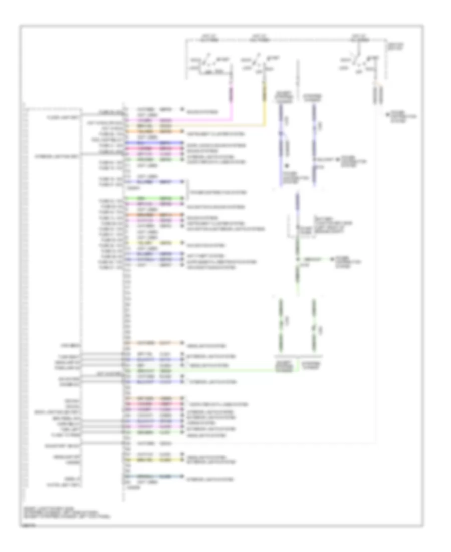
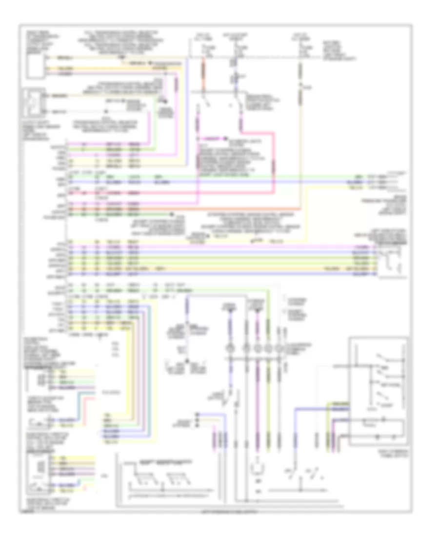
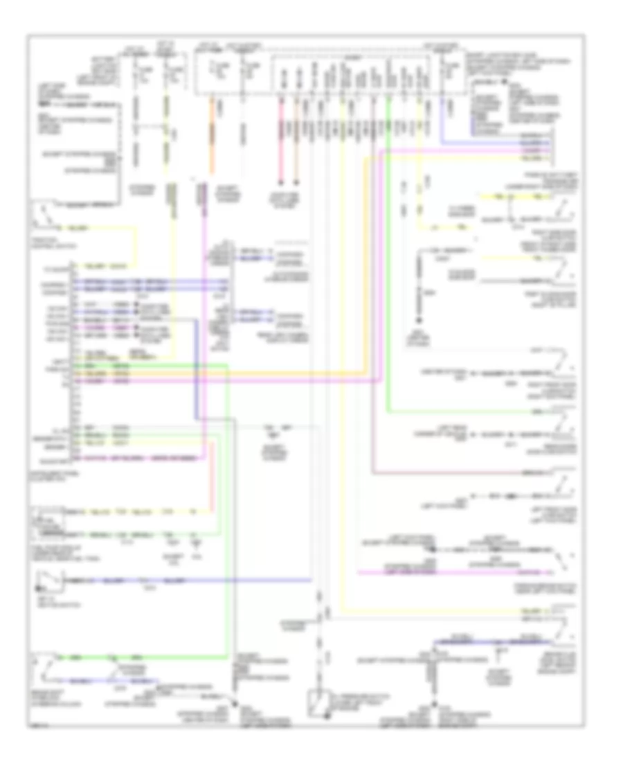
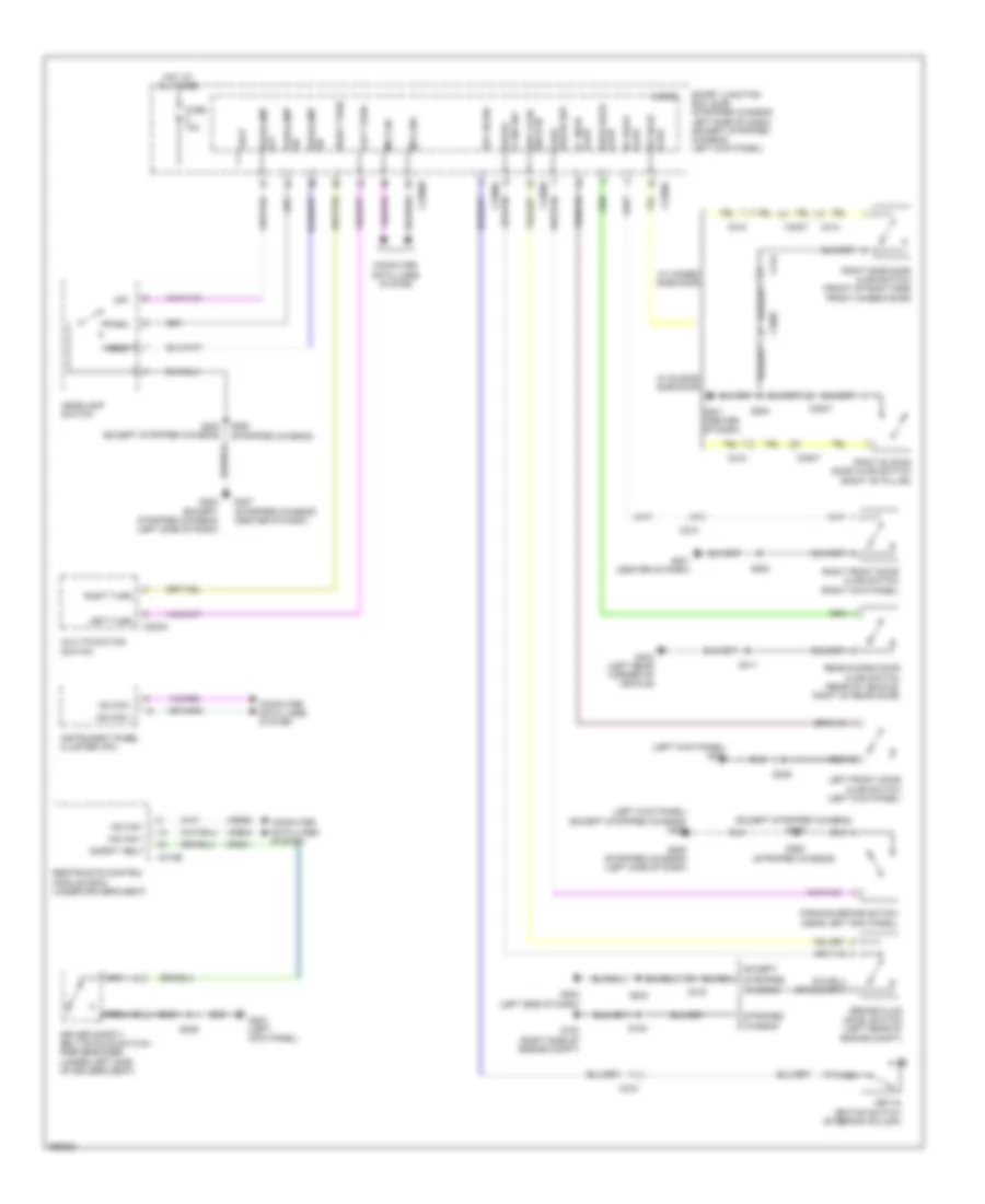
BODY CONTROL MODULES
Body Control Modules Wiring Diagram (1 of 3) for Ford E-450 Super Duty 2013
List of elements for Body Control Modules Wiring Diagram (1 of 3) for Ford E-450 Super Duty 2013:
- (not used)
- Acc
- Air conditioning system
- Anti-theft system
- Back lighting led (fet)
- Battery junction box (bjb) (left front of engine compt)
- Brk pedal sw
- C219
- C2280a
- C2280b
- C291
- Cbp28
- Cbp29
- Cbp33
- Cbp35
- Cbp36
- Cbp37
- Cbp41
- Cbp42
- Cbp46
- Ccb08
- Cdc32
- Cdc33
- Cdc34
- Ce336
- Clf17
- Clf18
- Clf23
- Clf27
- Cln28
- Cls32
- Cls34
- Cls39
- Cls41
- Computer data lines system
- Crh02
- Dim sw gnd
- Dimmer sw
- Dome lp
- Door locks & sound systems
- Except stripped chassis
- Exterior lights system
- Flash to pass
- Floor lamp (fet)
- Fog lamp relay
- Fuse 14, 10a
- Fuse 15, 10a
- Fuse 16, 15a
- Fuse 20, 15a
- Fuse 26, 10a
- Fuse 27, 20a
- Fuse 28, 5a
- Fuse 29, 5a
- Fuse 30, 5a
- Fuse 31, 10a
- Fuse 33, 10a
- Fuse 34, 5a
- Fuse 35, 10a
- Fuse 36, 5a
- Fuse 37, 10a
- Fuse 39, 20a
- Fuse 40, 20a
- Fuse 41, 15a
- Fuse 42, 10a
- Fuse 43, 10a
- Fuse 46, 7.5a
- Hazard
- Headlamp off
- Headlamp on
- Headlights system
- High beam
- Horn relay
- Horns system
- Hot at all times
- Hot in run
- Hot in run or acc
- Hot in start
- Ignition switch
- Instrument cluster system
- Interior lighting (fet)
- Interior lights system
- Lock
- Ms can+
- Ms can-
- Navigation & exterior lights systems
- Navigation & sound systems
- Navigation system
- Off
- Parklamp on
- Power distribution system
- Rln29
- Run
- Run/start ign sw
- S139
- Sbp14
- Sbp20
- Sbp26
- Sbp27
- Sbp39
- Sbp40
- Smart junction box (sjb) (stripped chassis: left side of dash) (except stripped chassis: left kick panel)
- Sound systems
- Start
- Start diode
- Stripped chassis
- Turn left
- Turn right
- Vdb06
- Vdb07
- Vln04
- Vln18
- Vln33
- White light (fet)
Body Control Modules Wiring Diagram (2 of 3) for Ford E-450 Super Duty 2013
List of elements for Body Control Modules Wiring Diagram (2 of 3) for Ford E-450 Super Duty 2013:
- (except cutaway) s240
- (except stripped chassis)
- (left kick panel) (except stripped chassis) g203
- (left side of dash)
- (not used)
- (stripped chassis)
- (stripped chassis) g205
- 3rd row seat enable (fet)
- Battery saver relay
- Bsi (fet)
- C2095
- C2280c
- C2280d
- Cbp32
- Cbp35
- Cbp41
- Cbp43
- Cbp47
- Cdc30
- Cet53
- Cln09
- Cls18
- Cls19
- Cls23
- Cls27
- Cls30
- Cmc25
- Cpl11
- Cpl26
- Cpl31
- Cpl36
- Cpl39
- Cpl42
- Cpl43
- Cpl51
- Cpl52
- Df door ajar
- Door lock relay
- Door locks & navigation systems
- Door locks system
- Dr door ajar
- Driver door unlock relay
- Exterior lights system
- Fuse 1, 30a
- Fuse 10a
- Fuse 11, 10a
- Fuse 12, 7.5a
- Fuse 13, 5a
- Fuse 14, 10a
- Fuse 18, 20a
- Fuse 19, 25a
- Fuse 2, 15a
- Fuse 3, 15a
- Fuse 32, 10a
- Fuse 35, 10a
- Fuse 38, 20a
- Fuse 4, 30a
- Fuse 41, 15a
- Fuse 43, 10a
- Fuse 46, 7.5a
- Fuse 47, 30a
- G203 (except stripped chassis) (left kick panel)
- Gd133
- Hot at all times
- Instrument cluster system
- Interior lights system
- Key in ignition
- Keypad illum (fet)
- Liftgate glass release relay
- Liftgate rel (fet)
- Logic gnd
- Lr stop/turn lamp (fet)
- Lr turn lamp (fet)
- Mirrors system
- Navigation system
- Park brake
- Park lamp relay
- Pf door ajar
- Power distribution system
- Power gnd
- Power windows system
- Pr door ajar
- Puddle lamp (fet)
- Pulse train (fet)
- Red
- Rr stop/turn lamp (fet)
- Rr turn lamp (fet)
- S239
- S250
- S317 (cutaway)
- Sbp01
- Sbp13
- Shift interlock system
- Smart junction box (sjb) (stripped chassis: left side of dash) (except stripped chassis: left kick panel)
- Trim lock
- Trim unlock
- Vbatt
Body Control Modules Wiring Diagram (3 of 3) for Ford E-450 Super Duty 2013
List of elements for Body Control Modules Wiring Diagram (3 of 3) for Ford E-450 Super Duty 2013:
- (not used)
- Accessory delay relay
- Batt-plus
- Battery saver relay
- Brake fluid sw
- Brake fluid sw rtn
- C2280e
- C2280f
- C2280g
- Cbp44
- Cbp45
- Cdc55
- Clf04
- Clf05
- Clf08
- Cls21
- Cls25
- Cls30
- Cmc19
- Door lock relay
- Driver door unlock relay
- Exterior lights system
- Fog lamp relay
- Fuse 44, 10a
- Fuse 45, 5a
- Headlights system
- High beam relay
- Horn relay
- Horns system
- Instrument cluster system
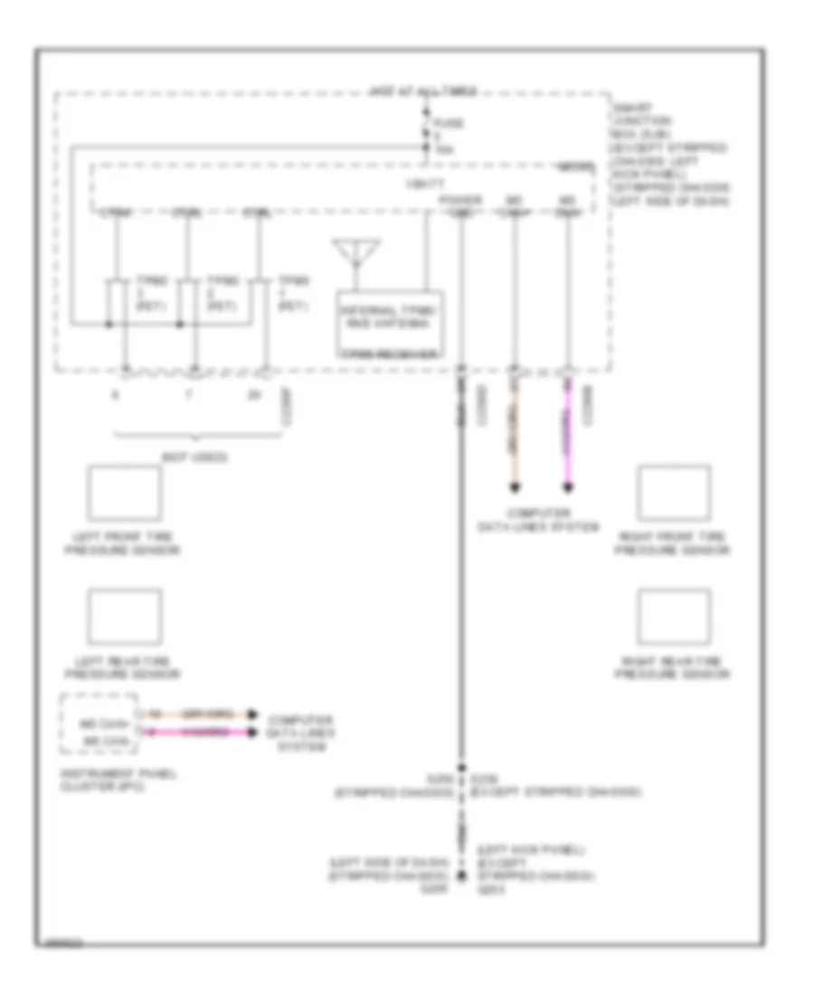
- Internal rke/ tpms antenna tpms receiver
- Left low beam
- Lf turn lamp (fet)
- Lh corner lamp (fet)
- Liftgate glass release relay
- Park lamp relay
- Power distribution system
- Red
- Rf turn lamp (fet)
- Rh corner lamp (fet)
- Right low beam
- Rmc19
- Run/start relay
- Sdc02
- Smart junction box (sjb) (stripped chassis: left side of dash) (except stripped chassis: left kick panel)
- Srh01
- Tpms 1 (fet)
- Tpms 2 (fet)
- Tpms 3 (fet)
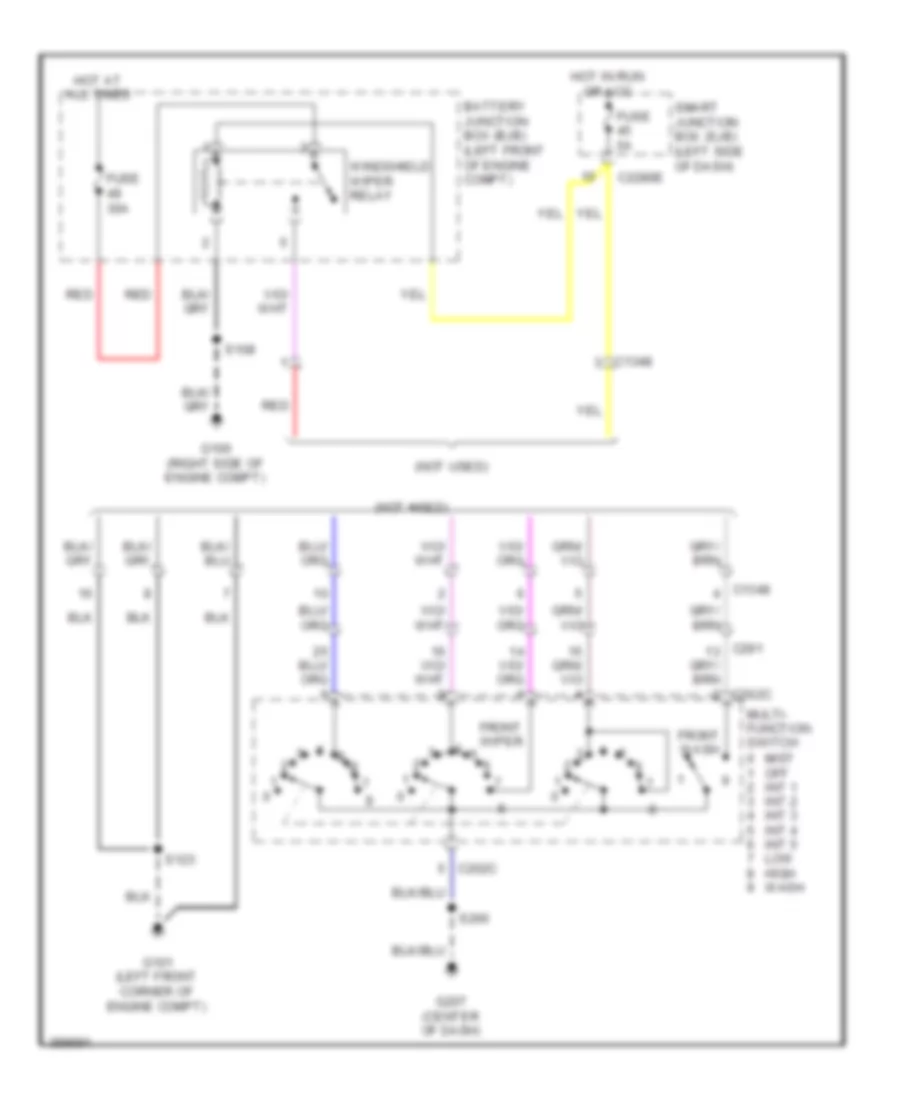
- Wiper/washer system
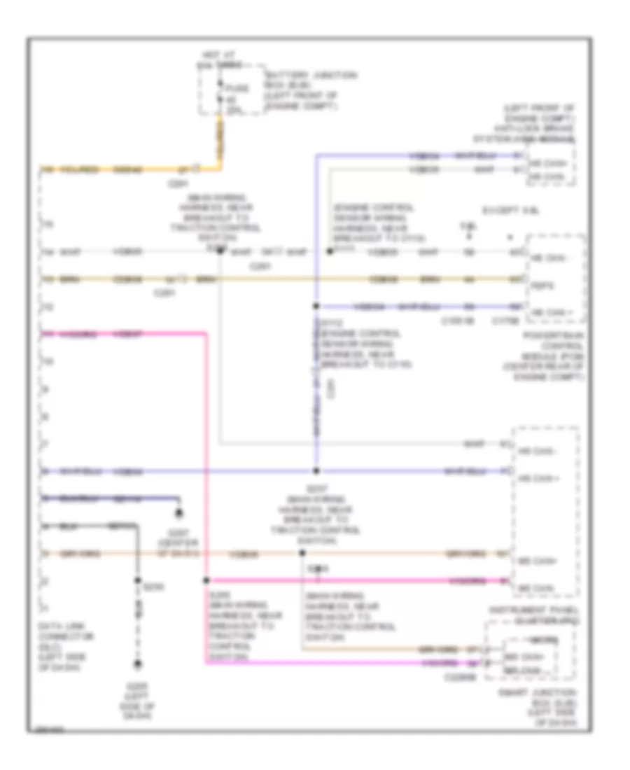
COMPUTER DATA LINES
Computer Data Lines Wiring Diagram, with Stripped Chassis for Ford E-450 Super Duty 2013
List of elements for Computer Data Lines Wiring Diagram, with Stripped Chassis for Ford E-450 Super Duty 2013:
- (engine control sensor wiring harness, near breakout to c110)
- (engine control sensor wiring harness, near breakout to c110) s111
- (left front of engine compt) anti-lock brake system (abs) module
- (main wiring harness, near breakout to traction control switch)
- (main wiring harness, near breakout to traction control switch) s258
- 6.8l
- Battery junction box (bjb) (left front of engine compt)
- C1551b
- C175b
- C2280b
- C291
- Cdb08
- Data link connector (dlc) (left side of dash)
- Except 6.8l
- Feps
- Fuse 15a
- G205 (left side of dash)
- G207 (center of dash)
- Gd114
- Gd133
- Hot at all times
- Hs can +
- Hs can -
- Hs can+
- Hs can-
- Instrument panel cluster (ipc)
- Micro
- Ms can+
- Ms can-
- Powertrain control module (pcm) (center rear of engine compt)
- S250
- S255 (main wiring harness, near breakout to traction control switch)
- S256
- S257 (main wiring harness, near breakout to traction control switch)
- Sbb42
- Smart junction box (sjb) (left side of dash)
- Vdb04
- Vdb05
- Vdb06
- Vdb07
- Vdbo4
- Vdbo5
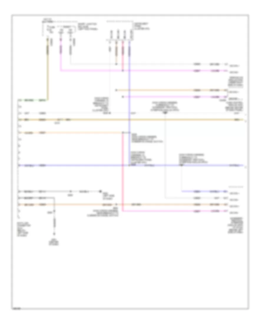
Computer Data Lines Wiring Diagram, without Stripped Chassis with Navigation (1 of 2) for Ford E-450 Super Duty 2013
List of elements for Computer Data Lines Wiring Diagram, without Stripped Chassis with Navigation (1 of 2) for Ford E-450 Super Duty 2013:
- (main wiring harness, in breakout to accessory protocol interface module (apim)) s266
- (main wiring harness, in breakout to accessory protocol interface module (apim)) s267
- (main wiring harness, in breakout to instrument panel cluster (ipc)) s224
- (main wiring harness, in breakout to instrument panel cluster (ipc)) s225
- (main wiring harness, near breakout to overdrive cancel switch)
- Accessory protocol interface module (apim) (w/ sync) (behind left side of dash)
- Audio control module (acm) (behind center of dash panel)
- C219
- C2280a
- C2280b
- C240b
- Cdb08
- Data link connector (dlc) (below left side of dash)
- Fuse 15a
- G201 (center of dash)
- G202 (left side
- Gd114
- Gd115
- Hot at all times
- Hs can +
- Hs can -
- Instrument panel cluster (ipc)
- Micro
- Ms can +
- Ms can -
- Of dash)
- Parking aid module (pam) (under right side of dash)
- S228
- S229 (main wiring harness, near breakout to overdrive cancel switch)
- S263
- S264
- Sbp20
- Smart junction box (sjb) (left kick panel)
- Vdb04
- Vdb05
- Vdb06
- Vdb07
Computer Data Lines Wiring Diagram, without Stripped Chassis with Navigation (2 of 2) for Ford E-450 Super Duty 2013
List of elements for Computer Data Lines Wiring Diagram, without Stripped Chassis with Navigation (2 of 2) for Ford E-450 Super Duty 2013:
- (engine control sensor wiring harness, near breakout to c192)
- (engine control sensor wiring harness, near breakout to c192) s126
- (engine control sensor wiring harness, near breakout to g105)
- (left front corner
- (main wiring harness, near breakout to trailer brake control (tbc) module)
- (t-box jumper harness, near breakout to modem antenna) s270
- (w/ advance trac)
- 6.8l
- Abs test connector (w/ advance trac)
- Anti-lock brake system (abs) module (left front of engine compt)
- C1551b
- C175b
- C210
- C2108
- C219
- C310b
- Cdb08
- Except 6.8l
- Feps
- Harness, near breakout to modem antenna)
- Hs can +
- Hs can -
- Hsc1-a
- Hsc1-c
- Hsc2-c
- Of engine compt)
- Powertrain control module (pcm) (left rear of engine compt)
- Restraints control module (rcm) (under driver's seat)
- S111 (w/ advance trac) (engine control sensor wiring harness, near breakout to g105)
- S112
- S127
- S221
- S222 (main wiring harness, near breakout to trailer brake control (tbc) module)
- S271 (t-box jumper hsc2-a
- S301 (taillights wiring harness, near breakout to g203)
- S302
- Telematics module (crew chief)
- Trailer brake control (tbc) module (crew chief) (top center of dash)
- Trailer brake control (tbc) module (except crew chief) (top center of dash)
- Vdb04
- Vdb05
- W/ advance trac
- W/o advance trac
Computer Data Lines Wiring Diagram, without Stripped Chassis without Navigation (1 of 2) for Ford E-450 Super Duty 2013
List of elements for Computer Data Lines Wiring Diagram, without Stripped Chassis without Navigation (1 of 2) for Ford E-450 Super Duty 2013:
- (center of dash)
- (main wiring harness, in breakout accessory protocol interface module (apim)) s266
- (main wiring harness, in breakout to instrument panel cluster (ipc)) s224
- (main wiring harness, in breakout to instrument panel cluster (ipc)) s225
- (main wiring harness, near breakout to overdrive cancel switch)
- (under right
- Accessory protocol interface module (apim) (w/ sync) (behind left side of dash)
- Audio control module (acm) (behind center of dash panel)
- C219
- C2280a
- C2280b
- C2408b
- C240b
- Cdb08
- Data link connector (dlc) (below left side of dash)
- Fuse 15a
- G201 (center of dash)
- G202 (left side
- Gd114
- Gd115
- Global positioning system module (gpsm) (w/ sync) (behind left side of dash)
- Hot at all times
- Hs can +
- Hs can -
- In dash computer
- Instrument panel cluster (ipc)
- Micro
- Ms can +
- Ms can -
- Of dash)
- Parking aid module (pam)
- S228
- S229 (main wiring harness, near breakout to overdrive cancel switch)
- S263
- S264
- S267 (main wiring harness, in breakout accessory protocol interface module (apim))
- Sbp20
- Side of dash)
- Smart junction box (sjb) (left kick panel)
- Vdb04
- Vdb05
- Vdb06
- Vdb07
Computer Data Lines Wiring Diagram, without Stripped Chassis without Navigation (2 of 2) for Ford E-450 Super Duty 2013
List of elements for Computer Data Lines Wiring Diagram, without Stripped Chassis without Navigation (2 of 2) for Ford E-450 Super Duty 2013:
- (engine control sensor wiring harness, near breakout to c192)
- (engine control sensor wiring harness, near breakout to c192) s126
- (engine control sensor wiring harness, near breakout to g105)
- (left front corner
- (main wiring harness, near breakout to trailer brake control (tbc) module)
- (t-box jumper harness, near breakout to modem antenna)
- (w/ advance trac)
- 6.8l
- Abs test connector (w/ advance trac)
- Anti-lock brake system (abs) module (left front of engine compt)
- C1551b
- C175b
- C210
- C2108
- C219
- C310b
- Cdb08
- Except 6.8l
- Feps
- Harness, near breakout to modem antenna)
- Hs can +
- Hs can -
- Hsc1-a
- Hsc1-c
- Hsc2-c
- Of engine compt)
- Powertrain control module (pcm) (left rear of engine compt)
- Restraints control module (rcm) (under driver's seat)
- S111 (w/ advance trac)
- S112
- S127
- S221
- S222 (main wiring harness, near breakout to trailer brake control (tbc) module)
- S270
- S271 (t-box jumper hsc2-a
- S301 (taillights wiring harness, near breakout to g203)
- S302
- Telematics module (crew chief)
- Trailer brake control (tbc) module (crew chief) (top center of dash)
- Trailer brake control (tbc) module (except crew chief) (top center of dash)
- Vdb04
- Vdb05
- W/ advance trac
- W/o advance trac
CRUISE CONTROL
5.4L
5.4L, Cruise Control Wiring Diagram for Ford E-450 Super Duty 2013
List of elements for 5.4L, Cruise Control Wiring Diagram for Ford E-450 Super Duty 2013:
- (5.4l: transmission control selector neutral switch wiring harness, near breakout to torqshift transmission) (6.8l: transmission control selector neutral switch wiring harness, near breakout to c192) s101
- (6.8l: top left side of engine)
- (except stripped chassis)
- (except stripped chassis: left front of engine compt) (stripped chassis: right side of engine compt)
- (left side of dash, above accelerator pedal) accelerator pedal position sensor
- (right rear of transmission) (torqshift) output shaft speed (oss) sensor
- (stripped stripped: engine control sensor wiring harness, near breakout to brake fluid level switch) (except stripped chassis: engine control sensor wiring harness, near breakout to c192)
- (transmission control selector neutral switch wiring harness, near breakout to speed selector assembly)
- 4.6l
- 5.4l
- 5.4l & 6.8l
- 6.8l
- App1
- App2
- Apprtn
- Apprtn2
- Appvref
- Appvref2
- Battery junction box (bjb) (left front of engine compt)
- Bfp
- Bpp
- Bps
- Brake pedal position switch (under left side of dash)
- Brake pressure transducer (5.4l & 6.8l) (left side of engine compt)
- C1551b
- C1551e
- C1551t
- C155t
- C175b
- C175e
- C175t
- C218b
- C218c
- C219
- C291
- Ccb08
- Ce412
- Ce426
- Ces09
- Clockspring (steering wheel)
- Coast
- Electronic throttle control (etc) motor (5.4l: top of engine)
- Electronic throttle control (etc) motor (top of engine)
- Engine controls system
- Etc ref
- Etc rtn
- Except stripped chassis
- Exterior lights system
- Fuse 10a
- Fuse 20a
- G105
- G202 (left side of dash)
- G207 (center of dash)
- Gd120
- Horn switch
- Horns system
- Hot at all times
- Hot in start or run
- Interior lights system
- Kapwr
- Lca16
- Le111
- Le134
- Le136
- Le137
- Left steering wheel switch
- Nca
- Off
- Oss
- Output shaft speed (oss) sensor (4r75e) (left side of transmission)
- Power gnd
- Powertrain control module (pcm) (except stripped chassis: left rear of engine compt) (stripped chassis: center rear of engine compt)
- Rca16
- Re134
- Re136
- Re137
- Re406
- Re407
- Res
- Res08
- Ret04
- Ret24
- Right steering wheel switch
- Rtn
- S102
- S104 (transmission control selector neutral switch wiring harness, near breakout to c192)
- S129
- S137
- S156
- S223 (except stripped chassis)
- S260 (stripped chassis)
- Sbb46
- Sccs
- Sccsrtn
- Set/accel
- Sig rtn
- Smart junction box (sjb))
- Solid state
- Sound systems
- Stripped chassis
- Tacm +
- Tacm -
- Throttle position sensor (tps) (top of engine, near air intake)
- Tp1
- Tp2
- Tr gnd
- Trans- missions system
- Transmissions system
- Ve701
- Ve702
- Ve818
- Ve819
- Ves10
- Vet26
- Vref
6.8L
6.8L, Cruise Control Wiring Diagram for Ford E-450 Super Duty 2013
List of elements for 6.8L, Cruise Control Wiring Diagram for Ford E-450 Super Duty 2013:
- (5.4l: transmission control selector neutral switch wiring harness, near breakout to torqshift transmission) (6.8l: transmission control selector neutral switch wiring harness, near breakout to c192) s101
- (6.8l: top left side of engine)
- (except stripped chassis)
- (except stripped chassis: left front of engine compt) (stripped chassis: right side of engine compt)
- (left side of dash, above accelerator pedal) accelerator pedal position sensor
- (right rear of transmission) (torqshift) output shaft speed (oss) sensor
- (stripped stripped: engine control sensor wiring harness, near breakout to brake fluid level switch) (except stripped chassis: engine control sensor wiring harness, near breakout to c192)
- (transmission control selector neutral switch wiring harness, near breakout to speed selector assembly)
- 4.6l
- 5.4l
- 5.4l & 6.8l
- 6.8l
- App1
- App2
- Apprtn
- Apprtn2
- Appvref
- Appvref2
- Battery junction box (bjb) (left front of engine compt)
- Bfp
- Bpp
- Bps
- Brake pedal position switch (under left side of dash)
- Brake pressure transducer (5.4l & 6.8l) (left side of engine compt)
- C1551b
- C1551e
- C1551t
- C155t
- C175b
- C175e
- C175t
- C218b
- C218c
- C219
- C291
- Ccb08
- Ce412
- Ce426
- Ces09
- Clockspring (steering wheel)
- Coast
- Electronic throttle control (etc) motor (5.4l: top of engine)
- Electronic throttle control (etc) motor (top of engine)
- Engine controls system
- Etc ref
- Etc rtn
- Except stripped chassis
- Exterior lights system
- Fuse 10a
- Fuse 20a
- G105
- G202 (left side of dash)
- G207 (center of dash)
- Gd120
- Horn switch
- Horns system
- Hot at all times
- Hot in start or run
- Interior lights system
- Kapwr
- Lca16
- Le111
- Le134
- Le136
- Le137
- Left steering wheel switch
- Nca
- Off
- Oss
- Output shaft speed (oss) sensor (4r75e) (left side of transmission)
- Power gnd
- Powertrain control module (pcm) (except stripped chassis: left rear of engine compt) (stripped chassis: center rear of engine compt)
- Rca16
- Re134
- Re136
- Re137
- Re406
- Re407
- Res
- Res08
- Ret04
- Ret24
- Right steering wheel switch
- Rtn
- S102
- S104 (transmission control selector neutral switch wiring harness, near breakout to c192)
- S129
- S137
- S156
- S223 (except stripped chassis)
- S260 (stripped chassis)
- Sbb46
- Sccs
- Sccsrtn
- Set/accel
- Sig rtn
- Smart junction box (sjb))
- Solid state
- Sound systems
- Stripped chassis
- Tacm +
- Tacm -
- Throttle position sensor (tps) (top of engine, near air intake)
- Tp1
- Tp2
- Tr gnd
- Trans- missions system
- Transmissions system
- Ve701
- Ve702
- Ve818
- Ve819
- Ves10
- Vet26
- Vref
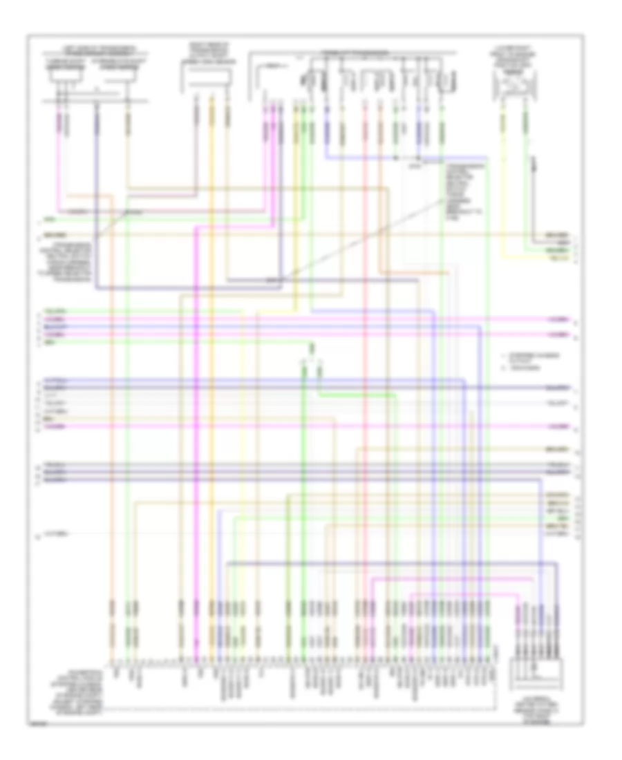
ENGINE PERFORMANCE
5.4L
5.4L, Engine Performance Wiring Diagram, with Torqshift (1 of 5) for Ford E-450 Super Duty 2013
List of elements for 5.4L, Engine Performance Wiring Diagram, with Torqshift (1 of 5) for Ford E-450 Super Duty 2013:
- (left side of engine compt) (except flex fuel) brake fluid pressure transducer
- (near fuel tank) evaporative emission (evap) canister vent valve
- (not used)
- Accr
- Air conditioning system
- App1
- App2
- Apprtn1
- Appvref1
- Battery junction box (bjb) (left front of engine compt)
- Bfp
- Bpp
- Bps
- C110
- C175b
- C219
- C263
- C291
- C310a
- Can+
- Can-
- Canv
- Cbb54
- Cbb75
- Ccb08
- Cdc12
- Cdc15
- Cdc35
- Ce114
- Ce302
- Ce326
- Ce336
- Ce515
- Ce608
- Ce912
- Ce913
- Ce914
- Ce924
- Ces09
- Ch302
- Computer data lines system
- Cr167
- Cruise control system
- Ens
- Except stripped chassis
- Fpc
- Fpm
- Fppwr
- Fprtn
- Fuel pump control module (under rear of vehicle, near fuel tank)
- Fuel pump module (under rear of vehicle, near fuel tank)
- Fuel sndr 1
- Fuel sndr rtn 1
- Fuse 10a
- G105 (stripped chassis: right side of engine compt) (except stripped chassis: left front of engine compt)
- G401 (left rear underbody of vehicle)
- Gd120
- Gd128
- Genmon
- Gnd
- Hot at all times
- Hs can-
- Iat
- Inertia fuel shutoff (ifs) switch (stripped chassis: under dash) (except stripped chassis: right kick panel)
- Inj pwrm
- Instrument panel cluster (ipc)
- Isp-r
- Le136
- Maf
- Mafrtn
- Nca
- Pcmrc
- Powertrain control module (stripped chassis: center rear of engine compt) (except stripped chassis: left rear of engine compt)
- Ptioc 1
- Pto
- Ptoeng
- Ptoil
- Ptorpm
- Pwr gnd
- Rca16
- Re136
- Re320
- Re515
- Res08
- Restraints control module (rcm) (under driver's seat)
- S125
- S129
- S407
- Sccs rtn
- Smc
- Smcs
- Smr
- Starting/charging system
- Stripped chassis
- Vdb05
- Ve225
- Ve518
- Ve701
- Ve702
- Ve740
- Ve807
- Vmc05
- Vpwr
- Vpwr fuel
- Vsout
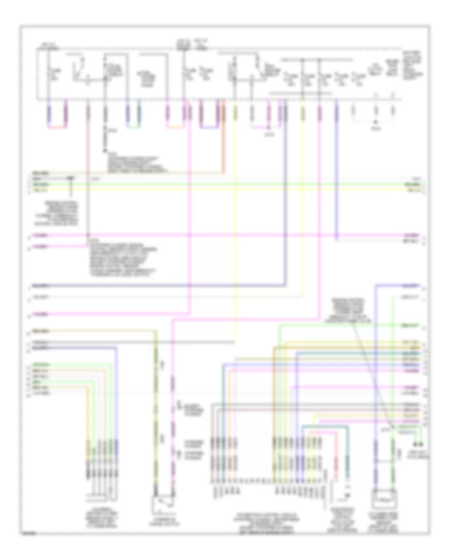
5.4L, Engine Performance Wiring Diagram, with Torqshift (2 of 5) for Ford E-450 Super Duty 2013
List of elements for 5.4L, Engine Performance Wiring Diagram, with Torqshift (2 of 5) for Ford E-450 Super Duty 2013:
- (exhaust system, left of transmission) (van/wagon) heated oxygen sensor (ho2s) 22
- (exhaust system, right of transmission) heated oxygen sensor (ho2s) 12
- (stripped chassis: engine control sensor wiring harness, near breakout to anti- lock brake system (abs) module) (except stripped chassis: engine control
- (stripped chassis: engine control sensor wiring harness, near breakout to brake fluid level switch) (except stripped chassis: engine control
- (transmission control selector neutral switch wiring harness, near breakout to c192)
- (transmission control selector neutral switch wiring harness, near breakout to c192) s104
- (under left side of dash) brake pedal position switch
- (van/wagon) s103
- Accelerator pedal position sensor (left side of dash, above accelerator pedal)
- Accs
- Apprtn2
- Appvref2
- Battery junction box (bjb) (left front of engine compt)
- C1033
- C110
- C134
- C175b
- C192
- Cbb75
- Cdb08
- Cdc10
- Ch421
- Cruise control system
- Exterior lights system
- Feps
- Ftp
- Ftpref
- Fuel tank pressure (ftp) sensor (fuel tank)
- Fuse 10a
- G105 (stripped chassis: right side of engine compt) (except stripped chassis: left front of engine compt)
- Gd120
- Gencom
- Hot at all times
- Hs can+
- Kapwr
- Lca16
- Le137
- Le230
- Level switch) (except stripped chassis: engine control sensor wiring harness, near breakout to c192)
- Lines system computer data
- Mass air flow/ air temperature (maf/iat) sensor (stripped chassis: top right side of engine) (except stripped chassis: center of engine compt)
- Nca
- Powertrain control module (stripped chassis: center rear of engine compt) (except stripped chassis: left rear of engine compt)
- Pwr gnd
- Re137
- Re407
- S117 (stripped chassis: engine control sensor wiring harness, near breakout to smart junction box (sjb)) (except stripped chassis: engine control sensor wiring harness, near breakout to c144)
- S125
- S131
- S137
- S156 (stripped chassis: engine control sensor wiring harness, near breakout to brake fluid
- Sbb46
- Sccs
- Sensor wiring harness, near breakout to brake fluid level switch)
- Sensor wiring harness, near breakout to windshield wiper motor)
- Sigrtn
- Stripped chassis & cutaway
- System air conditioning
- System starting/charging
- Van/wagon
- Vdb04
- Ve922
- Ves10
- Vpwr
- Vref
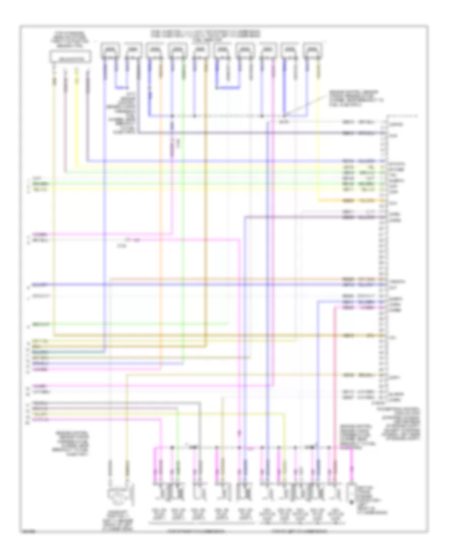
5.4L, Engine Performance Wiring Diagram, with Torqshift (3 of 5) for Ford E-450 Super Duty 2013
List of elements for 5.4L, Engine Performance Wiring Diagram, with Torqshift (3 of 5) for Ford E-450 Super Duty 2013:
- & cutway
- (left side of transmission) speed sensor assembly
- (lower right front of engine) crankshaft position (ckp) sensor
- (not used)
- (or ce239)
- (or ve745)
- (right rear of transmission) output shaft speed (oss) sensor
- (stripped chassis: center rear of engine compt) (except stripped chassis: left rear of engine compt)
- (transmission control selector neutral switch wiring harness, near breakout to speed selector assembly)
- (transmission control selector neutral switch wiring harness, near breakout to torqshift transmission)
- C175t
- C192
- C219
- C291
- Ce223
- Ce234
- Cet05
- Cet06
- Cet07
- Cet08
- Cet09
- Cet21
- Cet22
- Cet25
- Cet34
- Cet41
- Cet50
- Cet51
- Except stripped chassis
- Exterior
- Ho2s-12
- Ho2s-22
- Htr-12
- Htr-22
- Intermediate shaft speed sensor
- Iss
- Le111
- Lights system
- Nca
- Od cncl
- Oss
- Overdrive cancel switch
- Pc-a
- Powertrain control module
- Re406
- Ret04
- Ret24
- Rlc
- S100
- S101
- S102
- Sigrtn
- Sspc a
- Sspc b
- Sspc c
- Sspc d
- Sspc e
- Sspc-a
- Sspc-b
- Sspc-c
- Sspc-d
- Sspc-e
- Stripped chassis
- Tcc
- Tft
- Torqshift transmission
- Tr gnd
- Tr-p
- Tro_n
- Tro_p
- Tspc
- Tss
- Turbine shaft speed sensor
- Van/wagon
- Ve731
- Ve733
- Ve744
- Vet27
- Vet32
- Vet33
- Vref
5.4L, Engine Performance Wiring Diagram, with Torqshift (4 of 5) for Ford E-450 Super Duty 2013
List of elements for 5.4L, Engine Performance Wiring Diagram, with Torqshift (4 of 5) for Ford E-450 Super Duty 2013:
- (engine control sensor wiring harness & fuel charge, in breakout to crankshaft position sensor) s178
- (engine control sensor wiring harness & fuel charge, near breakout to fuel injector 8)
- A/c clutch relay
- Battery junction box (bjb) (left front of engine compt)
- C1046
- C175e
- Camshaft position sensor 11 (front of left cylinder head)
- Ce235
- Ce236
- Ce303
- Ce304
- Ce305
- Ce308
- Ce309
- Ce426
- Ckp+
- Cop1a
- Cop2d
- Cop3b
- Cop6e
- Cop7c
- Cylinder head temperature sensor (front of left cylinder head)
- De135
- Etc ref
- Etc rtn
- Evap canister purge valve (center top rear of engine)
- Fuel power motor diode
- Fuel pump relay
- Fuse 10a
- Fuse 20a
- Fuse 40a
- G100 (stripped chassis: right side of engine compt) (except stripped chassis: right front of engine compt)
- Hot at all times
- Hot in run or start
- Le134
- Nca
- Pcm power relay
- Powertrain control module (stripped chassis: center rear of engine compt) (except stripped chassis: left rear of engine compt)
- Re134
- Re405
- Red
- Reversing lamp relay
- S108
- S116
- S124
- S130 (stripped chassis: engine control sensor wiring harness, near breakout to anti-lock brake system (abs) module) (except stripped chassis: engine control sensor wiring harness, near breakout to brake fluid level switch)
- S174
- Shdrtn
- Sigrtn
- Tacm-
- Universal heated oxygen sensor (ho2s) 11 (rear of right cylinder bank)
- Universal heated oxygen sensor (ho2s) 21 (rear of left cylinder bank)
- Uo2shtr11
- Uo2shtr21
- Ve711
5.4L, Engine Performance Wiring Diagram, with Torqshift (5 of 5) for Ford E-450 Super Duty 2013
List of elements for 5.4L, Engine Performance Wiring Diagram, with Torqshift (5 of 5) for Ford E-450 Super Duty 2013:
- (engine control sensor wiring harness & fuel charge, near breakout to coil on
- (engine control sensor wiring harness & fuel charge, near breakout to coil on plug (cop) 7)
- (engine control sensor wiring harness & fuel charge, near breakout to fuel injector 1)
- (engine control sensor wiring harness & fuel charge, near breakout to fuel injector 2)
- (fuel injector 1, 2, 3 & 4: top of right cylinder bank) (fuel injector 5, 6, 7 & 8: top of left cylinder bank) fuel injector
- (top of left cylinder bank)
- (top of right cylinder bank)
- Battery junction box (bjb) (left front of engine compt)
- C134
- C175e
- Ce113
- Ce205
- Ce206
- Ce207
- Ce208
- Ce209
- Ce210
- Ce211
- Ce212
- Ce306
- Ce307
- Ce310
- Ce412
- Cht
- Ckp-
- Cmp1
- Coil on plug (cop) 1
- Coil on plug (cop) 2
- Coil on plug (cop) 3
- Coil on plug (cop) 4
- Coil on plug (cop) 5
- Coil on plug (cop) 6
- Coil on plug (cop) 7
- Coil on plug (cop) 8
- Cop4g
- Cop5f
- Cop8h
- Electronic throttle control (etc) motor (top of engine)
- Evapcp
- Fuse 15a
- Ignition trans- former capacitor 1 (top right front of engine)
- Ignition trans- former capacitor 2 (left front of engine)
- Inj1
- Inj2
- Inj3
- Inj4
- Inj5
- Inj6
- Inj7
- Inj8
- Knock sensor 1 (ks1) (top rear of engine)
- Ks1+
- Ks1-
- Le448
- Le449
- Le450
- Le451
- Le452
- Le453
- Nca
- Plug (cop) 7)
- Powertrain control module (pcm) (stripped chassis: center rear of engine compt) (except stripped chassis: left rear of engine compt)
- Re135
- Re323
- Re429
- S170
- S173
- S175
- S177
- Solid state
- Tacm+
- Throttle position sensor (tps) (top of engine, near air intake)
- Tp1
- Tp2
- Uo2s11
- Uo2s21
- Uo2sgref11
- Uo2sgref21
- Uo2spc11
- Uo2spc21
- Uo2spct11
- Uo2spct21
- Ve707
- Ve712
- Ve801
- Ve818
- Ve819
- Ve826
- Ve827
- Vrsrtn
5.4L, Engine Performance Wiring Diagram, without Torqshift (1 of 5) for Ford E-450 Super Duty 2013
List of elements for 5.4L, Engine Performance Wiring Diagram, without Torqshift (1 of 5) for Ford E-450 Super Duty 2013:
- (left side of engine compt) (except flex fuel) brake fluid pressure transducer
- (near fuel tank) evaporative emission (evap) canister vent valve
- (not used)
- Accr
- Air conditioning system
- App1
- App2
- Apprtn1
- Appvref1
- Battery junction box (bjb) (left front of engine compt)
- Bfp
- Bpp
- Bps
- C110
- C175b
- C219
- C263
- C291
- C310a
- Canv
- Cbb54
- Cbb75
- Ccb08
- Cdc12
- Cdc15
- Cdc35
- Ce114
- Ce302
- Ce326
- Ce336
- Ce515
- Ce608
- Ce912
- Ce913
- Ce914
- Ce924
- Ces09
- Ch302
- Chassis: left front of engine compt)
- Computer data lines system
- Cr167
- Cruise control system
- Ens
- Except stripped chassis
- Fpc
- Fpm
- Fppwr
- Fprtn
- Fuel
- Fuel pump control module (under rear of vehicle, near fuel tank)
- Fuel pump module (under rear of vehicle, near fuel tank)
- Fuel sndr rtn 1
- Fuse 10a
- G105 (stripped chassis: right side of engine compt) (except stripped
- G105 (stripped chassis: right side of engine compt) (except stripped chassis: left front of engine compt)
- G401 (left rear underbody of vehicle)
- Gd120
- Gd128
- Genmon
- Gnd
- Hot at all times
- Hs can+
- Hs can-
- Iat
- Inertia fuel shutoff (ifs) switch (stripped chassis:
- Inj pwrm
- Instrument panel cluster (ipc)
- Isp-r
- Le136
- Maf
- Mafrtn
- Nca
- Pcmrc
- Powertrain control module (pcm) (stripped chassis: center rear of engine compt) (except stripped chassis: left rear of engine compt)
- Ptioc 1
- Pto
- Ptoeng
- Ptoil
- Ptorpm
- Pwr gnd
- Rca16
- Re136
- Re320
- Re515
- Res08
- Restraints control module (rcm) (under driver's seat)
- Right kick panel)
- S125
- S129
- S407
- Sccs rtn
- Smc
- Smcs
- Smr
- Sndr 1
- Starting/charging system
- Stripped chassis
- Stripped chassis:
- Under dash) (except
- Vdb05
- Ve225
- Ve518
- Ve701
- Ve702
- Ve740
- Ve807
- Vmc05
- Vpwr
- Vpwr fuel
- Vsout
5.4L, Engine Performance Wiring Diagram, without Torqshift (2 of 5) for Ford E-450 Super Duty 2013
List of elements for 5.4L, Engine Performance Wiring Diagram, without Torqshift (2 of 5) for Ford E-450 Super Duty 2013:
- (exhaust system, left of transmission) (van/wagon) heated oxygen sensor (ho2s) 22
- (exhaust system, right of transmission)
- (left side of transmission) output shaft speed sensor (oss)
- (left side of transmission) turbine shaft speed sensor (tss)
- (stripped chassis: engine control sensor wiring harness, near breakout to anti- lock brake system (abs) module) (except stripped chassis: engine control
- (stripped chassis: engine control sensor wiring harness, near breakout to brake fluid level switch) (except stripped chassis: engine control
- (stripped chassis: engine control sensor wiring harness, near breakout to brake fluid level switch) c110 (except stripped chassis: engine control sensor wiring harness, near breakout to c192)
- (stripped chassis: right side of engine compt) (except stripped
- (transmission control selector neutral switch wiring harness, near breakout to c192) s104
- (under left side of dash) brake pedal position switch
- Accelerator pedal position sensor (left side of dash, above accelerator pedal)
- Accs
- Apprtn2
- Appvref2
- Battery junction box (bjb) (left front of engine compt)
- C1033
- C110
- C134
- C175b
- C192
- Cbb75
- Cdb08
- Cdc10
- Ch421
- Chassis: left front of engine compt)
- Chassis: left rear of engine compt)
- Cruise control system
- Exterior lights system
- Feps
- Ftp
- Ftpref
- Fuel tank pressure (ftp) sensor (fuel tank)
- Fuse 10a
- G105
- G105 (stripped chassis: right side of engine compt) (except stripped chassis: left front of engine compt)
- Gd120
- Gencom
- Heated oxygen sensor (ho2s) 12
- Hot at all times
- Hs can+
- Kapwr
- Lca16
- Le137
- Le230
- Lines system computer data
- Mass air flow/ intake air temperature (maf/iat) sensor (top right side of engine)
- Nca
- Pwr gnd
- Pwr gnd powertrain control module (stripped chassis: center rear of engine compt) (except stripped
- Re137
- Re407
- S117 (stripped chassis: engine control sensor wiring harness, near breakout to smart junction box (sjb)) (except stripped chassis: engine control sensor wiring harness, near breakout to c144)
- S125
- S131
- S137
- S156
- Sbb46
- Sccs
- Sensor wiring harness, near breakout to brake fluid level switch)
- Sensor wiring harness, near breakout to windshield wiper motor)
- Sigrtn
- Stripped chassis & cutaway
- System air conditioning
- System starting/charging
- Van/wagon
- Vdb04
- Ve922
- Ves10
- Vpwr
- Vref
5.4L, Engine Performance Wiring Diagram, without Torqshift (3 of 5) for Ford E-450 Super Duty 2013
List of elements for 5.4L, Engine Performance Wiring Diagram, without Torqshift (3 of 5) for Ford E-450 Super Duty 2013:
- (left side of transmission) digital transmission range (dtr) sensor
- (lower right front of engine) crankshaft position (ckp) sensor
- (not used)
- (or ce239)
- (or ve745)
- (stripped chassis: center rear of engine compt) (except stripped chassis: left rear of engine compt)
- 4r75e transmission
- C175t
- C192
- C219
- Ce223
- Ce234
- Ce418
- Cet05
- Cet18
- Cet19
- Cet21
- Cet22
- Cet34
- Epc
- Ho2s-12
- Ho2s-22
- Htr-12
- Htr-22
- N r
- Nca
- Od cncl
- Oss
- Overdrive cancel switch
- Powertrain control module (pcm)
- Re406
- Red
- Sigrtn
- Ssa
- Ssb
- Stripped chassis
- Tcc
- Tft
- Tr1
- Tr2
- Tr3a
- Tr4
- Tro_n
- Tro_p
- Tss
- Ve731
- Ve733
- Vet26
- Vet27
- Vet28
- Vet29
- Vet30
- Vet31
- Vet33
5.4L, Engine Performance Wiring Diagram, without Torqshift (4 of 5) for Ford E-450 Super Duty 2013
List of elements for 5.4L, Engine Performance Wiring Diagram, without Torqshift (4 of 5) for Ford E-450 Super Duty 2013:
- (engine control sensor wiring harness & fuel charge, in breakout to crankshaft position sensor) s178
- (engine control sensor wiring harness & fuel charge, near breakout to fuel injector 8)
- (except stripped chassis: engine control sensor wiring harness, near breakout to brake fluid level switch) (stripped chassis: engine control sensor wiring harness, near breakout to anti-lock brake system (abs) module) s130
- A/c clutch relay
- Battery junction box (bjb) (left front of engine compt)
- C1046
- C175e
- C192
- Camshaft position sensor (front of left cylinder head)
- Ce235
- Ce236
- Ce303
- Ce304
- Ce305
- Ce308
- Ce309
- Ce426
- Ckp+
- Cop1a
- Cop2d
- Cop3b
- Cop6e
- Cop7c
- Cylinder head temperature sensor (front of left cylinder head)
- De135
- Etc ref
- Etc rtn
- Evap canister purge valve (center top rear of engine)
- Fuel pump motor diode
- Fuel pump relay
- Fuse 10a
- Fuse 20a
- Fuse 40a
- G100 (except stripped chassis: right front of engine compt) (stripped chassis: right side of engine compt)
- Hot at all times
- Hot in start or run
- Le134
- Nca
- Pcm power relay
- Powertrain control module (pcm) (stripped chassis: center rear of engine compt) (except stripped chassis: left rear of engine compt)
- Re134
- Re405
- Red
- Reversing lamp relay
- S108
- S116
- S124
- S174
- Shdrtn
- Sigrtn
- Tacm-
- Universal heated oxygen sensor (ho2s) 11 (rear of right cylinder bank)
- Universal heated oxygen sensor (ho2s) 21 (rear of left cylinder bank)
- Uo2shtr11
- Uo2shtr21
- Ve711
5.4L, Engine Performance Wiring Diagram, without Torqshift (5 of 5) for Ford E-450 Super Duty 2013
List of elements for 5.4L, Engine Performance Wiring Diagram, without Torqshift (5 of 5) for Ford E-450 Super Duty 2013:
- (engine control sensor wiring harness & fuel charge, near breakout to coil on
- (engine control sensor wiring harness & fuel charge, near breakout to coil on plug (cop) 7)
- (engine control sensor wiring harness & fuel charge, near breakout to fuel injector 1)
- (engine control sensor wiring harness & fuel charge, near breakout to fuel injector 2)
- (fuel injectors 1, 2, 3 & 4: top of right cylinder bank) (fuel injectors 5, 6, 7 & 8: top of left cylinder bank) fuel injectors
- (top of left cylinder bank)
- (top of right cylinder bank)
- Battery junction box (bjb) (left front of engine compt)
- C1046
- C134
- C175e
- Ce113
- Ce205
- Ce206
- Ce207
- Ce208
- Ce209
- Ce210
- Ce211
- Ce212
- Ce306
- Ce307
- Ce310
- Ce412
- Cht
- Ckp-
- Cmp 11
- Coil on plug (cop) 1
- Coil on plug (cop) 2
- Coil on plug (cop) 3
- Coil on plug (cop) 4
- Coil on plug (cop) 5
- Coil on plug (cop) 6
- Coil on plug (cop) 7
- Coil on plug (cop) 8
- Cop4g
- Cop5f
- Cop8h
- Electronic throttle control (etc) motor (top of engine)
- Evapcp
- Fuse 15a
- Ignition trans- former capacitor 1 (top right front of engine)
- Ignition trans- former capacitor 2 (left front of engine)
- Inj1
- Inj2
- Inj3
- Inj4
- Inj5
- Inj6
- Inj7
- Inj8
- Knock sensor 1 (ks1) (top rear of engine)
- Ks1+
- Ks1-
- Le448
- Le449
- Le450
- Le451
- Le452
- Le453
- Nca
- Plug (cop) 7)
- Powertrain control module (pcm) (stripped chassis: center rear of engine compt) (except stripped chassis: left rear of engine compt)
- Re135
- Re323
- Re429
- S170
- S173
- S175
- S177
- Solid state
- Tacm+
- Throttle position sensor (top of engine, near air intake)
- Tp1
- Tp2
- Uo2s11
- Uo2s21
- Uo2sgref11
- Uo2sgref21
- Uo2spc11
- Uo2spc21
- Uo2spct11
- Uo2spct21
- Ve707
- Ve712
- Ve801
- Ve818
- Ve819
- Ve826
- Ve827
- Vrsrtn
6.8L
6.8L, Engine Performance Wiring Diagram (1 of 5) for Ford E-450 Super Duty 2013
List of elements for 6.8L, Engine Performance Wiring Diagram (1 of 5) for Ford E-450 Super Duty 2013:
- (left side of engine compt) (except flex fuel) brake fluid pressure transducer
- (near fuel tank) evaporative emission (evap) canister vent valve
- (not used)
- Accr
- Air conditioning system
- App1
- App2
- Apprtn1
- Appvref1
- Battery junction box (bjb) (left front of engine compt)
- Bfp
- Bpp
- Bps
- C110
- C1551b
- C219
- C263
- C291
- C310a
- Canv
- Cbb54
- Ccb08
- Cdc12
- Cdc15
- Cdc35
- Ce114
- Ce302
- Ce326
- Ce336
- Ce515
- Ce608
- Ce912
- Ce913
- Ce914
- Ce924
- Ces09
- Cet21
- Cet22
- Ch302
- Chassis
- Computer data lines system
- Cr167
- Cruise control system
- Ens
- Except stripped
- Fpc
- Fpm
- Fppwr
- Fprtn
- Fuel pump control module (under rear of vehicle, near fuel tank)
- Fuel pump module (under rear of vehicle, near fuel tank)
- Fuel sndr 1
- Fuel sndr rtn 1
- Fuse 10a
- G105 (stripped chassis: right side of engine compt) (except stripped chassis: left front of engine compt)
- G401 (left rear underbody of vehicle)
- Gd120
- Gd128
- Genmon
- Gnd
- Hot at all times
- Hs can+
- Hs can-
- Iat
- Inertia fuel shutoff (ifs) switch (under dash)
- Inj pwrm
- Instrument panel cluster (ipc)
- Isp-r
- Le136
- Maf
- Mafrtn
- Nca
- Pcmrc
- Powertrain control module (pcm) (stripped chassis: center rear of engine compt) (except stripped chassis: left rear of engine compt)
- Pto
- Ptoeng
- Ptoic 1
- Ptoic 2
- Ptoind
- Pwr gnd
- Rca16
- Re136
- Re320
- Re515
- Res08
- Restraints control module (rcm) (under driver's seat)
- S129
- S407
- Sccs rtn
- Smc
- Smcs
- Smr
- Starting/ charging system
- Starting/charging system
- Stripped chassis
- Tro n
- Tro p
- Ve225
- Ve518
- Ve701
- Ve702
- Ve740
- Ve807
- Vmc05
- Vpwr fuel
- Vsout
6.8L, Engine Performance Wiring Diagram (2 of 5) for Ford E-450 Super Duty 2013
List of elements for 6.8L, Engine Performance Wiring Diagram (2 of 5) for Ford E-450 Super Duty 2013:
- (exhaust system, left of transmission) (van/wagon) heated oxygen sensor (ho2s) 22
- (exhaust system, right of transmission) (stripped chassis/ cutway) heated oxygen sensor (ho2s) 12
- (exhaust system, right of transmission) (van/wagon) heated oxygen sensor (ho2s) 12
- (stripped chassis: engine control sensor wiring harness, near breakout to anti- lock brake system (abs) module) (except stripped chassis: engine control
- (stripped chassis: engine control sensor wiring harness, near breakout to brake fluid level switch) (except stripped chassis: engine control
- (transmission control selector neutral switch wiring harness, near breakout to c192) (van/wagon) s104
- (transmission control selector neutral switch wiring harness, near breakout to torqshift transmission)
- (under left side of dash) brake pedal position switch
- Accelerator pedal position sensor (left side of dash, above accelerator pedal)
- Accs
- Apprtn2
- Appvref2
- Battery junction box (bjb) (left front of engine compt)
- C110
- C134
- C139
- C1551b
- C192
- Cbb75
- Cdc10
- Cet41
- Ch421
- Cruise control system
- Evap purge valve (top left rear of engine)
- Exterior lights system
- Ftp
- Fuel tank pressure (ftp) sensor (fuel tank)
- Fuse 10a
- G105 (stripped chassis: right side of engine compt) (except stripped chassis: left front of engine compt)
- Gd120
- Gencom
- Hot at all times
- Hs can+
- Hs can-
- Kapwr
- Lca16
- Le137
- Le230
- Level switch) (except stripped chassis: engine control sensor wiring harness, near breakout to c192)
- Lights system exterior
- Mass air flow/ air temperature (maf/iat) sensor (top right side of engine)
- Nca
- Powertrain control module (stripped chassis: right side of engine compt) (except stripped chassis: left front of engine compt)
- Pwr gnd
- Re137
- Re407
- Rlc
- S103
- S117 (stripped chassis: engine control sensor wiring harness, near breakout to smart junction box (sjb)) (except stripped chassis: engine control sensor wiring harness, near breakout to c144)
- S125
- S131
- S137
- S156 (stripped chassis: engine control sensor wiring harness, near breakout to brake fluid
- Sbb46
- Sccs
- Sensor wiring harness, near breakout to brake fluid level switch)
- Sensor wiring harness, near breakout to windshield wiper motor)
- Sigrtn
- System air conditioning
- System data lines computer
- System starting/charging
- Vdb04
- Vdb05
- Ve922
- Ves10
- Vpwr
- Vref
6.8L, Engine Performance Wiring Diagram (3 of 5) for Ford E-450 Super Duty 2013
List of elements for 6.8L, Engine Performance Wiring Diagram (3 of 5) for Ford E-450 Super Duty 2013:
- (left side of transmission) speed sensor assembly
- (lower right front of engine) crankshaft position (ckp) sensor
- (right rear of transmission) output shaft speed (oss) sensor
- (stripped chassis: center rear of engine compt) (except stripped chassis: left rear of engine compt)
- (transmission control selector neutral switch wiring harness, near breakout to c192)
- (transmission control selector neutral switch wiring harness, near breakout to speed selector transmission)
- C1551t
- Ce233
- Ce234
- Ce235
- Ce236
- Ce239
- Cet05
- Cet06
- Cet07
- Cet08
- Cet09
- Cet25
- Cet34
- Cet50
- Cet51
- Cutway
- Ho2s-12
- Ho2s-22
- Htr-12
- Htr-22
- Intermediate shaft speed sensor
- Iss
- Le111
- Le448
- Le449
- Le450
- Le451
- Le452
- Le453
- Nca
- Od cncl
- Oss
- Pc a
- Pc-a
- Powertrain control module
- Re242
- Ret04
- Ret24
- S100
- S101
- S102
- Sig rtn
- Sspc a
- Sspc b
- Sspc c
- Sspc e
- Sspc-a
- Sspc-b
- Sspc-c
- Sspc-d
- Sspc-e
- Stripped chassis/
- Tcc
- Tft
- Torqshift transmission
- Tr gnd
- Tr-p
- Tspc
- Tss
- Turbine shaft speed sensor
- Universal heated oxygen sensor (ho2s) 21 (top right of engine)
- Uo2s-11
- Uo2s-21
- Uo2sgref-11
- Uo2sgref-21
- Uo2shtr-11
- Uo2shtr-21
- Uo2spc-11
- Uo2spc-21
- Uo2spct-11
- Uo2spct-21
- Van/wagon
- Ve731
- Ve733
- Ve744
- Ve745
- Ve826
- Ve827
- Vet27
- Vet32
- Vet33
- Vref
6.8L, Engine Performance Wiring Diagram (4 of 5) for Ford E-450 Super Duty 2013
List of elements for 6.8L, Engine Performance Wiring Diagram (4 of 5) for Ford E-450 Super Duty 2013:
- (engine control sensor wiring harness & fuel charge, in breakout to powertrain control module (pcm)
- (engine control sensor wiring harness & fuel charge, near breakout to evap canister purge valve)
- (info not available)
- A/c clutch relay
- Battery junction box (bjb) (left front of engine compt)
- C1046
- C1551e
- C192
- C219
- C291
- Ce205
- Ce206
- Ce207
- Ce209
- Ce210
- Ce211
- Ce212
- Ce214
- Ce303
- Ce304
- Ce306
- Ce309
- Ce412
- Ce426
- Cop1a
- Cop2e
- Cop4i
- Cop7f
- Cylinder head temperature sensor (front of left cylinder head)
- Electronic throttle control (etc) motor (top left side of engine)
- Except stripped chassis
- Fuel power motor diode
- Fuel pump relay
- Fuse 10a
- Fuse 15a
- Fuse 20a
- Fuse 40a
- G100 (stripped chassis: right side of engine compt) (except stripped chassis: right front of engine compt)
- Hot at all times
- Hot in run or start
- Inj1
- Inj10
- Inj2
- Inj3
- Inj5
- Inj6
- Inj7
- Inj8
- Nca
- Overdrive cancel switch
- Pcm power relay
- Powertrain control module (stripped chassis: center rear of engine compt) (except stripped chassis: left rear of engine compt)
- Rever- sing lamp relay
- S108
- S116
- S124
- S130 (stripped chassis: engine control sensor wiring harness, near breakout to anti-lock brake system (abs) module) (except stripped chassis: engine control sensor wiring harness, near breakout to brake fluid level switch)
- S171
- S172
- Stripped chassis
- Tacm+
- Tacm-
- Universal heated oxygen sensor (ho2s) 11 (rear of left cylinder bank)
6.8L, Engine Performance Wiring Diagram (5 of 5) for Ford E-450 Super Duty 2013
List of elements for 6.8L, Engine Performance Wiring Diagram (5 of 5) for Ford E-450 Super Duty 2013:
- (engine control sensor wiring harness & fuel charge, near breakout to fuel injector 1)
- (engine control sensor wiring harness & fuel charge, near breakout to fuel injector 3)
- (engine control sensor wiring harness & fuel charge, near breakout to fuel injector 6)
- (fuel injector 1, 2, 3, 4 & 5: top of right cylinder bank) (fuel injector 6, 7, 8, 9 & 10: top of left cylinder bank) fuel injector
- (top of engine, near air intake) throttle position sensor (tps)
- (top of left cylinder bank)
- (top of right cylinder bank)
- C134
- C1551e
- Camshaft position 11 (cmp 11) sensor (front of left cylinder head)
- Ce113
- Ce208
- Ce213
- Ce305
- Ce307
- Ce308
- Ce310
- Ce311
- Ce312
- Cht
- Ckp+
- Ckp-
- Cmp11
- Coil on plug (cop)
- Coil on plug (cop) 1
- Coil on plug (cop) 2
- Coil on plug (cop) 3
- Coil on plug (cop) 4
- Coil on plug (cop) 5
- Cop10d
- Cop3g
- Cop5c
- Cop6b
- Cop8h
- Cop9j
- De135
- Etc ref
- Etc rtn
- Evapcp
- Ignition trans- former capacitor 1 (left front of cylinder bank)
- Inj4
- Inj9
- Le134
- Powertrain control module (pcm) (stripped chassis: center rear of engine compt) (except stripped chassis: left rear of engine compt)
- Re134
- Re135
- Re405
- Re429
- S170
- S173 (engine control sensor wiring harness & fuel charge, near breakout to fuel injector 8)
- S175
- S177
- Shdrtn
- Sigrtn
- Solid state
- Tp1
- Tp2
- Ve706
- Ve711
- Ve712
- Ve818
- Ve819
- Vrs rtn
EXTERIOR LIGHTS
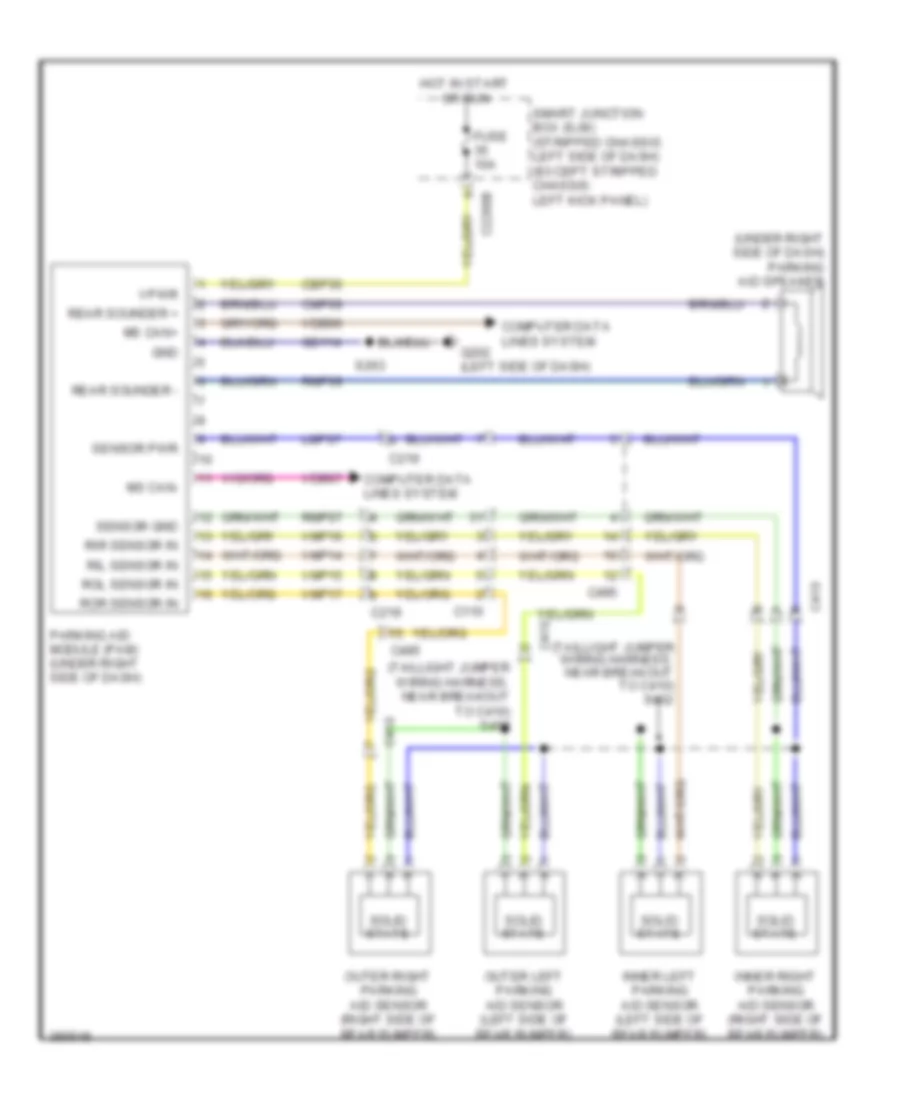
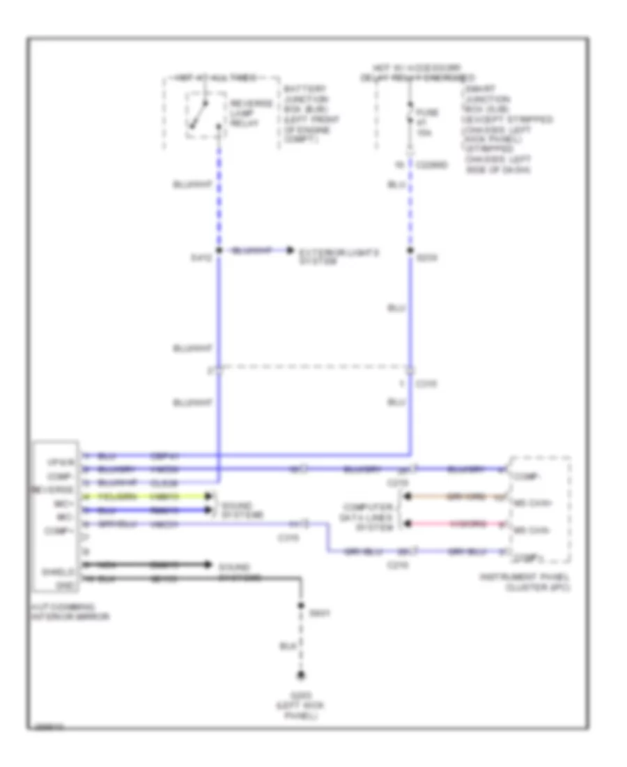
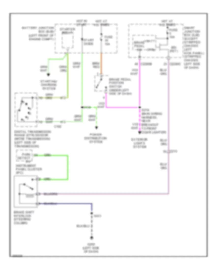
Backup Lamps Wiring Diagram for Ford E-450 Super Duty 2013
List of elements for Backup Lamps Wiring Diagram for Ford E-450 Super Duty 2013:
- (except stripped chassis: left side of engine compt) (stripped
- (not used)
- (not used) (stripped chassis & cutaway)
- (stripped chassis & cutaway)
- 4.6l & 6.8l
- 4r75e
- 5.4l
- Auto- dimming interior mirror (if equipped)
- Battery junction box (bjb) (left front of engine compt)
- C110
- C1348
- C1551b
- C175t
- C192
- C263
- C315
- C432
- C494
- C495
- Cet41
- Chassis: left front corner of engine compt)
- Digital transmission range (dtr) sensor (left side of transmission)
- Fuse 10a
- Fuse 15a
- Fuse 20a
- G101
- G403 (left rear corner of vehicle)
- Hot at all times
- Hot in run or start
- Left reversing lamp (except stripped chassis & cutaway)
- Powertrain control module (pcm) (except stripped chassis: left rear of engine compt) (stripped chassis: center rear of engine compt)
- Rear view camera display mirror
- Reversing lamp relay
- Right reversing lamp (except stripped chassis & cutaway)
- Rlc
- S123
- S124
- S142 (except stripped chassis: engine control sensor wiring harness, near breakout to g105) (stripped chassis: engine control sensor wiring harness, near breakout to horn)
- S411
- Trailer tow connector (7-pin) (except stripped chassis & cutaway) (under rear bumper)
- W/ torqshift
- Wiring harness, near breakout to rear doors door ajar switch) (except stripped chassis & cutaway) s412
Exterior Lamps Wiring Diagram, Cutaway (1 of 2) for Ford E-450 Super Duty 2013
List of elements for Exterior Lamps Wiring Diagram, Cutaway (1 of 2) for Ford E-450 Super Duty 2013:
- (engine control senor wiring harness, in breakout to c110) s120
- (not used)
- Brake pedal sw
- C110
- C144
- C202a
- C202b
- C215
- C2280b
- C2280d
- C2280e
- C2280f
- C263
- C432
- Control
- Ctrl
- Fuse 10a
- Fuse 15a
- Fuse 20a
- G107 (left front of engine compt)
- G108 (right front of engine compt)
- G202 (left side of dash)
- Hazard
- Head
- Headlamp switch
- Hot at all times
- Left front park/ turn lamp
- Left front side lamp
- Left turn
- Lf turn lamp (fet)
- Low beam
- Lr stop/ turn lamp (fet)
- Multi- function switch
- Off
- Park
- Park lamp relay
- Rf turn lamp (fet)
- Right front park/ turn lamp
- Right front side lamp
- Right turn
- Rr stop/ turn lamp (fet)
- S162
- S164 (dash panel to headlamp junction wiring harness, near breakout to left frontal restraints sensor)
- S165
- S223
- Smart junction box (sjb)
- Vbatt
Exterior Lamps Wiring Diagram, Cutaway (2 of 2) for Ford E-450 Super Duty 2013
List of elements for Exterior Lamps Wiring Diagram, Cutaway (2 of 2) for Ford E-450 Super Duty 2013:
- (left side of dash)
- (not used)
- (under left side of dash) brake pedal position switch
- 6.8l
- Battery charge trailer tow relay
- Battery junction box (bjb) (left front of engine compt)
- Bpp
- Bps
- Brake shift interlock (steering column)
- C110
- C1551b
- C175b
- C2026
- C210
- C275
- C291
- C4000
- C432
- C494
- Cat06
- Cat09
- Cat17
- Ccb08
- Ces09
- Except 6.8l
- Fuse 10a
- Fuse 20a
- Fuse 30a
- G100
- G205
- G402 (rear of left frame rail)
- Hot at all times
- Hot in run
- Hot in run or start
- Left turn/stop trailer tow relay
- Parking lamp trailer tow relay
- Powertrain control module (pcm) (left rear of engine compt)
- Rat08
- Red
- Resistor (left side of dash)
- Right turn/stop trailer tow relay
- S108
- S117
- S137
- S245 (main wiring harness, near breakout to g207)
- S250
- Trailer tow connector (4-pin) (if equipped) (under rear bumper)
Exterior Lamps Wiring Diagram, Stripped Chassis for Ford E-450 Super Duty 2013
List of elements for Exterior Lamps Wiring Diagram, Stripped Chassis for Ford E-450 Super Duty 2013:
- (engine control sensor wiring harness, near breakout to smart junction box (sjb))
- (left side of dash) smart junction box (sjb)
- (main wiring harness, near breakout to g207)
- (not used)
- (rear of left frame rail) g402
- (under left side of dash) brake pedal position switch
- 6.8l
- All times
- Battery charge trailer tow relay
- Battery junction box (bjb) (left front of engine compt)
- Bpp
- Bps
- Brake pedal sw
- Brake shift interlock (steering column)
- C1010
- C110
- C1551b
- C175b
- C2026
- C202a
- C202b
- C2280b
- C2280c
- C2280d
- C2280e
- C2280f
- C275
- C291
- C4000
- C432
- C494
- Cat06
- Cat09
- Cat17
- Ccb08
- Ces09
- Control
- Ctrl
- Except 6.8l
- Fuse 10a
- Fuse 15a
- Fuse 20a
- Fuse 30a
- G100 (right side of engine compt)
- G205 (left side of dash)
- G207 (center of dash)
- Hazard
- Head
- Headlamp switch
- Hot at
- Hot at all times
- Hot in run
- Hot in start and run
- Left turn/ stop trailer tow relay
- Lf turn lamp (fet)
- Low beam
- Lr stop/ turn lamp (fet)
- Lr turn lamp (fet)
- Multi-function switch
- Off
- Park
- Park lamp relay
- Parking lamp trailer tow relay
- Powertrain control module (pcm) (center rear of engine compt)
- Red
- Resistor (left side of dash)
- Rf turn lamp (fet)
- Right turn/stop trailer tow relay
- Rr stop/ turn lamp (fet)
- Rr turn lamp (fet)
- S108
- S120
- S137
- S242
- S245 (main wiring harness, near breakout to g207)
- S249 (main wiring harness, near breakout to c2026)
- S250
- S260
- Trailer tow connector (4-pin) (if equipped) (under rear bumper)
- Turn left
- Turn right
- Vbatt
GROUND DISTRIBUTION
Ground Distribution Wiring Diagram (1 of 5) for Ford E-450 Super Duty 2013
List of elements for Ground Distribution Wiring Diagram (1 of 5) for Ford E-450 Super Duty 2013:
- (4r75e transmission) digital transmission range (dtr) sensor
- (except stripped chassis) windshield washer pump motor
- (except stripped chassis) windshield wiper motor
- (except stripped chassis: left side of engine compt) (stripped chassis: left front corner of engine compt)
- (except stripped chassis: right front of engine compt) (stripped chassis: right side
- (left front of engine compt) (except stripped chassis) battery junction box (bjb)
- (left front of engine compt) battery junction box (bjb)
- (not used)
- (stripped chassis) (not used)
- (stripped chassis) horn
- A/c compressor clutch field coil
- Battery
- Battery charge trailer tow relay
- Battery secondary (dual battery w/ aft axle tank)
- Battery secondary (dual battery w/ midship tank)
- Blower motor relay
- Blower motor resistor
- Body builder ground
- Brake fluid level switch
- C1010
- C134
- C1348
- C192
- Fuel pump relay
- G100
- G101
- G109 (4.6l & 5.4l) (right front of engine compt)
- G109 (6.8l) (right front of engine compt)
- G120 (4.6l & 5.4l) (right rear of engine)
- G120 (6.8l) (right rear of engine)
- G121 (4.6l & 5.4l) (w/ dual battery) (front right side frame rail)
- G121 (6.8l) (w/ dual battery) (front right side frame rail)
- G300 (right underbody of vehicle)
- G400 (right rear underbody of vehicle)
- Left turn/stop trailer tow relay
- Of engine compt)
- Parking lamp trailer tow relay
- Right turn/stop trailer tow relay
- Run/ start relay
- Run/start relay
- S123 (except stripped chassis: engine control sensor wiring harness, near breakout to c144)
- Sensor wiring harness, near breakout to horn)
- Stripped chassis
- Upfitter relay 1
- Upfitter relay 2
- Upfitter relay 3
- Upfitter relay 4
- W/o dual battery
- Windshield wiper relay
- Wiring harness, near breakout to a/c cycling switch) (stripped chassis: engine control sensor wiring harness, near breakout to brake fluid level switch)
Ground Distribution Wiring Diagram (2 of 5) for Ford E-450 Super Duty 2013
List of elements for Ground Distribution Wiring Diagram (2 of 5) for Ford E-450 Super Duty 2013:
- & cutaway
- (not used)
- 4-pin trailer tow connector
- 7-pin trailer tow connector
- Abs test connector
- Accessory protocol interface module (apim)
- Anti-lock brake system (abs) module
- Brake fluid level switch
- Brake shift interlock
- C202a
- C202b
- C202c
- C218b
- C218c
- C219
- C275
- C300
- C4000
- C422
- C432
- C495
- Clock- spring (steering wheel)
- Customer access
- Cutaway
- Data link connector (dlc)
- Except stripped chassis
- G102 (except stripped chassis: left side of engine compt) (stripped chassis: left rear of engine compt)
- G103 (left side of engine compt)
- G202 (except stripped chassis) (left side of dash)
- G207 (stripped chassis) (center of dash)
- G208 (left kick panel)
- G402 (rear of left frame rail)
- Global positioning system module (gpsm)
- Headlamp switch
- Instrument panel cluster (ipc)
- Left steering wheel switch
- Multi-function switch
- Parking aid module (pam)
- Passive anti-theft transceiver
- S223 (main wiring harness, near breakout to c210)
- S260 (main wiring harness, near breakout to g207)
- S263 (main wiring harness, near breakout to c219)
- Stripped chassis
- W/ advance trac
- W/o advance trac
- Wagon/van
Ground Distribution Wiring Diagram (3 of 5) for Ford E-450 Super Duty 2013
List of elements for Ground Distribution Wiring Diagram (3 of 5) for Ford E-450 Super Duty 2013:
- (6.8l) brake pedal position switch
- (except 6.8l) mass air flow/intake air temperature (maf/iat) sensor
- (interior lights wiring harness, near breakout to c315)
- (left kick panel) smart junction box (sjb)
- (not used)
- (stripped chassis: right side of engine compt)
- (w/ auto- dimming interior mirror) auto- dimming interior mirror
- (w/ rear view camera display mirror w/o navigation) rear view camera display mirror
- 6.8l
- Auxiliary cargo lamp
- C1033
- C1551b
- C175b
- C2280d
- C2403
- C265
- C300
- C3133
- C315
- C925
- Cargo lamp
- Cutaway
- Driver safety belt buckle switch/ pretensioner
- Driver side door lock switch
- Driver side front seat control switch
- Except 6.8l
- Except cutaway
- Except cutaway & full headliner
- Exterior rear view mirror switch
- Front interior/ map lamps assembly
- G105 (except stripped chassis: left front of engine compt)
- G203 (except stripped chassis) (left kick panel)
- G204 (except stripped chassis) (left kick panel)
- Gnd cable
- High mounted stoplamp
- Left front door ajar switch
- Master window adjust switch
- Nca
- Parking brake switch
- Powertrain control module (pcm)
- Rear power point
- Resistor
- S239 (taillights wiring harness, near breakout to c263)
- S240 (taillights wiring harness, near breakout to g203)
- S317 (taillights wiring harness, near breakout to g203)
- S501 (left front door window regulator wiring harness, near breakout to driver side front power window motor)
- S906
- Second row cargo lamp
- Second row interior lamp
- Third row cargo lamp
- Third row interior lamp
- Tool link antenna module
- W/ full headliner
- Wiring harness, near breakout to c192) (stripped chassis: engine control sensor wiring harness, near breakout to g105)
Ground Distribution Wiring Diagram (4 of 5) for Ford E-450 Super Duty 2013
List of elements for Ground Distribution Wiring Diagram (4 of 5) for Ford E-450 Super Duty 2013:
- (except cutaway) license plate lamp
- (w/ rear video camera) video camera
- Auxiliary blower motor relay
- Auxiliary blower motor speed relay
- Breakout to g401)
- C405
- C406
- Fuel pump control module
- Fuel pump module shield
- G108 (except stripped chassis) (right front of engine compt)
- G401 (left rear underbody of vehicle)
- G403 (except stripped chassis) (left rear corner of vehicle)
- Left rear park/stop/ turn lamp
- Left reversing lamp
- Mounted stoplight)
- Nca
- Rear doors ajar switch
- Rear doors lock switch
- Right front park/turn lamp
- Right front side lamp
- Right headlamp
- Right rear park/stop/ turn lamp
- Right reversing lamp
- S405 (rear license plate lamp wiring harness, near breakout
- S411 (taillights wiring harness, near breakout to high
- To right rear speaker)
- W/ aero headlamps
- W/o aero headlamps
Ground Distribution Wiring Diagram (5 of 5) for Ford E-450 Super Duty 2013
List of elements for Ground Distribution Wiring Diagram (5 of 5) for Ford E-450 Super Duty 2013:
- (left side of dash) smart junction box (sjb)
- (t-box jumper harness, near breakout to modem antenna)
- (w/ 110v power inverter) dc/ac inverter module
- (w/ aero headlamps)
- (w/ hinged side door) right side door ajar switch
- (w/ navigation) audio amplifier
- (w/ navigation) audio control module (acm)
- (w/ sliding door) right sliding door ajar switch
- (w/o aero headlamps)
- (w/o navigation) audio control module (acm)
- Base audio
- C2108
- C214
- C2280d
- C2385b
- C2403
- C2408a
- C240a
- C294b
- C294c
- C294e
- C3007
- C3047
- C314
- Cigar lighter)
- Climate control assembly
- Crew chief
- Data link connector (dlc)
- Except crew chief
- Front cigar lighter
- G107 (except stripped chassis) (left front of engine compt)
- G200 (except stripped chassis) (right side of dash)
- G201 (except stripped chassis) (center of dash)
- G205 (stripped chassis) (left side of dash)
- Horn
- In-dash computer
- Instrument panel power point 1
- Instrument panel power point 2
- Left front park/turn lamp
- Left front side lamp
- Left headlamp
- Parking brake switch
- Passenger air bag deactivation (pad) switch
- Passenger side door lock switch
- Resistor
- Right front door ajar switch
- S216 (main wiring harness, near breakout to front
- S250 (main wiring harness, near breakout to g207)
- S264 (main wiring harness, near breakout to audio control module (acm))
- S265 (main wiring harness, near breakout to g201)
- S273
- Telematics module
- Temperature blend door actuator
- To g200)
- Traction control switch
- Trailer brake control (tbc) module
- Upfitter switch
HEADLIGHTS
Headlights Wiring Diagram for Ford E-450 Super Duty 2013
List of elements for Headlights Wiring Diagram for Ford E-450 Super Duty 2013:
- (dash panel to headlamp junction wiring harness, near breakout to left frontal restraints sensor) s163
- (except stripped chassis) s223
- (not used)
- C1010
- C144
- C202b
- C2280b
- C2280e
- Computer data lines system
- Control
- Except stripped chassis
- Ftp
- Fuse 10a
- Fuse 15a
- G107 (left front of engine compt)
- G108 (right front of engine compt)
- G202 (except stripped chassis) (left side of dash)
- G207 (stripped chassis) (center of dash)
- Head
- Headlamp off
- Headlamp switch
- High
- High beam
- High beam relay
- Hot at all times
- Hs can +
- Hs can -
- Instrument panel cluster (ipc)
- Interior lights system
- Left headlamp
- Left low beam (fet)
- Low
- Micro
- Ms can +
- Ms can -
- Multi-function switch
- Off
- On headlamp
- On parklamp
- Park
- Pass flash to
- Right headlamp
- Right low beam (fet)
- S162
- S165
- S260 (stripped chassis)
- Smart junction box (sjb) (except stripped chassis: left kick panel) (stripped chassis: left side of dash)
- Stripped chassis
- W/ aero headlamps
- W/o aero headlamps
HORN
Horn Wiring Diagram, with Stripped Chassis for Ford E-450 Super Duty 2013
List of elements for Horn Wiring Diagram, with Stripped Chassis for Ford E-450 Super Duty 2013:
- 20a
- Battery junction box (bjb) (left front of engine compt)
- C218b
- C218c
- C291
- Clockspring (steering wheel)
- Fuse 34
- G101 (left front corner of engine compt)
- G207 (center of dash)
- Horn (right front of engine compt)
- Horn relay
- Horn switch
- Hot at all times
- Left steering wheel switch
- S123
- S260
Horn Wiring Diagram, without Stripped Chassis for Ford E-450 Super Duty 2013
List of elements for Horn Wiring Diagram, without Stripped Chassis for Ford E-450 Super Duty 2013:
- C144
- C218b
- C218c
- C2280b
- C2280e
- Clockspring (steering wheel)
- Control
- Fuse 24 20a
- G107 (left front of engine compt)
- G202 (left side of dash)
- Horn (right front of engine compt)
- Horn relay
- Horn switch
- Hot at all times
- Left steering wheel switch
- S162
- S223
- Smart junction box (sjb) (left kick panel)
INSTRUMENT CLUSTER
Instrument Cluster Wiring Diagram for Ford E-450 Super Duty 2013
List of elements for Instrument Cluster Wiring Diagram for Ford E-450 Super Duty 2013:
- (center of dash)
- (except stripped chassis) s239
- (except stripped chassis) s263 s260 (stripped
- (except stripped chassis) s264 s250 (stripped chassis)
- (except stripped chassis: left kick panel)
- (left kick panel) (except stripped chassis) g203
- (left rear corner of vehicle) g403
- (left side of dash) (stripped chassis) g205
- (or cbb80)
- (stripped chassis)
- (stripped chassis) s260
- 6.8l
- Auto-dimming interior mirror
- Battery junction box (bjb) (left front of engine compt)
- Brake fluid level switch (left rear of engine compt)
- Brake shift interlock (steering column)
- Brk fluid sw rtn
- C110
- C134
- C210
- C219
- C2280a
- C2280b
- C2280c
- C2280f
- C275
- C291
- C3007
- C314
- C315
- Cbp29
- Cca15
- Cdc30
- Cet52
- Chassis)
- Cmc19
- Cmc24
- Cmc25
- Compass +
- Compass -
- Compass+
- Compass-
- Computer data lines system
- Cpl26
- Cpl31
- Cpl36
- Cpl39
- Display
- Except 6.8l
- Except stripped chassis
- Fluid sw brake
- Fuel gauge sensor
- Fuel pump module (under rear of vehicle, near fuel tank)
- Fuse 10a
- Fuse 5a
- G100 (stripped chassis) (right side of engine compt)
- G201
- G201 (center of dash)
- G201 (except stripped chassis) (center of dash)
- G202 (except stripped chassis) (left side of dash)
- G203 (left kick panel)
- G205 (stripped chassis) (left side of dash)
- G207 (stripped chassis) (center of dash)
- Gd114
- Hot at all times
- Hot in start or run
- Hs can +
- Hs can -
- Instrument panel cluster (ipc)
- Key in ign
- Key in ignition switch
- Left front door ajar switch (left kick panel)
- Lf door ajar
- Micro
- Mirror
- Mirror w/o navi- gation
- Ms can +
- Ms can -
- Nca
- Oil pressure switch (lower left front of engine)
- Oil sw
- Park brake
- Park sw
- Parking brake switch (near left kick panel)
- Passive anti-theft transceiver (under right side of dash)
- Pwr gnd
- Rear door ajar
- Rear doors door ajar switch
- Rear view camera display mirror
- Rf door ajar
- Right front door ajar switch (right kick panel)
- Right side door ajar switch (front of right side front hinged door)
- Right sliding door ajar switch (right "b" pillar)
- Rmc19
- Rmc32
- Rr door ajar
- Run/start
- S223 (except stripped chassis)
- S239
- S250 (stripped chassis)
- S264
- S411
- Sbp26 (or sbb31)
- Sender 1
- Sender rtn 1
- Smart junction box (sjb) (stripped chassis: left side of dash)
- Stripped chassis
- Tc on/off
- Traction control switch
- Vbatt
- Vdb04
- Vdb05
- Vdb06
- Vdb07
- Vmc11
- Vmc30
- Vmc31
- Vrt23
- Vrt24
- W/ auto- dimming interior
- W/ hinged side door
- W/ rear view camera
- W/ sliding side door
INTERIOR LIGHTS
Courtesy Lamps Wiring Diagram for Ford E-450 Super Duty 2013
List of elements for Courtesy Lamps Wiring Diagram for Ford E-450 Super Duty 2013:
- (interior lights wiring harness, near breakout to second row interior lamp) s904
- (left rear corner of vehicle)
- (main wiring harness, near breakout to headlight switch)
- (not used)
- (not used) (cutaway)
- (taillights wiring harness, near breakout to second row cargo lamp) s312
- Auxiliary cargo lamp (except cutaway & full headliner)
- Battery saver relay
- C110
- C2095
- C210
- C2280a
- C2280b
- C2280c
- C2280d
- C264
- C291
- C3007
- C314
- C315
- C432
- C925
- Cargo lamp (w/ full headliner)
- Ctsy
- Customer access connector (cutaway) (left "b" pillar)
- Dim sw gnd
- Dimmer sw
- Dome lp
- Except stripped chassis
- Exterior lights system
- Front interior/map lamps assembly
- Fuse 10a
- Fuse 15a
- G201 (center of dash)
- G203 (left kick panel)
- G403
- High mounted stop lamp
- Hot at all times
- Illumination dimmer
- Interior lighting (fet)
- Left front door ajar switch (left kick panel)
- Left vanity mirror lamp (w/ vanity mirror lamps)
- Lf dr ajar
- Micro
- Off
- Rear door ajar
- Rear doors door ajar switch (rear of vehicle, right of rear door)
- Rf dr ajar
- Right front door ajar switch (right kick panel)
- Right side door ajar switch (front of right side front hinged door)
- Right sliding door ajar switch (right "b" pillar)
- Right vanity mirror lamp (w/ vanity mirror lamps)
- Rr door ajar
- S230
- S239
- S240
- S264
- S304 (taillights wiring harness, near breakout to c3135)
- S411
- S901
- S902
- S903 (interior lights wiring harness, near breakout to second row interior lamp)
- S905 (interior lights wiring harness, near breakout to c315)
- Second row cargo lamp (except cutaway & full headliner)
- Second row interior lamp (w/ full headliner)
- Smart junction box (sjb) (except stripped chassis: left kick panel) (stripped chassis: left side of dash)
- Stripped chassis
- Third row cargo lamp (except cutaway & full headliner)
- Third row interior lamp (w/ full headliner)
- W/ hinged side door
- W/ sliding side door
Instrument Illumination Wiring Diagram for Ford E-450 Super Duty 2013
List of elements for Instrument Illumination Wiring Diagram for Ford E-450 Super Duty 2013:
- (behind center of dash panel) (base audio) audio control module
- (center of dash)
- (except stripped chassis)
- (except stripped chassis) s223 s260 (stripped chassis)
- (except stripped chassis: main wiring harness, near breakout to g201) (stripped chassis: main wiring harness, near breakout to g205) s219
- (left side of dash) (except stripped chassis) g202
- (main wiring harness, near breakout to headlight switch) s230
- (not used)
- (stripped chassis)
- Backlighting led (fet)
- C218b
- C218c
- C2280b
- C240a
- C294e
- Chassis)
- Climate control assembly
- Clockspring (steering wheel)
- Dim sw gnd
- Dimmer sw
- Dome lp
- Fuse 15a
- G201 (except stripped chassis) (center of dash)
- G205 (stripped chassis) (left side of dash)
- G207 (stripped chassis)
- Gnd
- Head
- Head- lamp off
- Head- lamp on
- Headlamp switch
- Hot at all times
- Illum
- Illumination dimmer
- Left steering wheel switch
- Micro
- Off
- Park
- Park- lamp on
- Right steering wheel switch
- S223 s260 (stripped
- S250
- S264 (except stripped chassis)
- Smart junction box (sjb) (except stripped chassis: left kick panel) (stripped chassis: left side of dash)
- Stripped chassis)
- Traction control switch
- Upfitter switch (except
- White led (fet)
NAVIGATION
Crew Chief Wiring Diagram for Ford E-450 Super Duty 2013
List of elements for Crew Chief Wiring Diagram for Ford E-450 Super Duty 2013:
- 5vpwr
- 5vtb
- 7-pin trailer tow connector (under rear bumper)
- Battery junction box (bjb) (left front of engine compt)
- Boo
- Bpp
- Brake
- Brake pedal position (bpp) switch (under left side of dash)
- C110
- C2108
- C219
- C2280b
- C422
- Can+
- Can-
- Cgnd
- Computer data lines system
- Front cigar lighter)
- Fuse 10a
- Fuse 30a
- G200 (right side of dash)
- Gnd
- Gnd-a
- Gnd1
- Hot at all times
- Hot in start or run
- Hs can +
- Hs can -
- Hsc1-a
- Hsc1-c
- Hsc2-a
- Hsc2-c
- Igrun-a
- Igrun-c
- Inline fuse (top center of dash)
- Modem antenna (top center of dash)
- Nca
- Pwr
- Pwr gnd
- Red
- Run start
- Rxd
- S272
- S273
- S274
- Smart junction box (sjb) (except stripped chassis: left kick panel) (stripped chassis: left side of dash)
- Tbo
- Telematics module
- Trailer
- Trailer brake control (tbc) module (top center of dash)
- Txd
- Vb-a
- Vb1
- Vbatt
In Dash Computer Wiring Diagram (1 of 2) for Ford E-450 Super Duty 2013
List of elements for In Dash Computer Wiring Diagram (1 of 2) for Ford E-450 Super Duty 2013:
- (main wiring harness, in breakout to audio input jack) s241
- (near top of left "b" pillar) tool link antenna 1
- (under side of roof, near right "b" pillar) tool link antenna 2
- (under side of roof, near right "d" pillar) tool link antenna 3
- 5v usb
- Ant
- Antenna
- Audio input jack
- Batt +
- Battery saver relay
- C gnd
- C2280a
- C2280b
- C2280d
- C2408a
- C2408b
- C2408c
- C2411
- Cbp28
- Cgnd
- Coax cable
- Computer data lines system
- Dme45
- Dtr
- Fuse 10a
- Fuse 20a
- Fuse 5a
- G201 (center of dash)
- G203 (left kick panel)
- Gd115
- Gnd
- Gnd cable
- Hot at all times
- Hot in start
- In-dash computer (center of dash)
- Lf spkr +
- Lf spkr -
- Lr spkr +
- Lr spkr -
- Micro
- Modem antenna (top center of dash)
- Ms can+
- Ms can-
- Nca
- Pwr cable
- Pwr gnd
- Red
- Rf in
- Rf spkr +
- Rf spkr -
- Rme07
- Rme09
- Rme10
- Rme12
- Rme45
- Rme46
- Rr spkr +
- Rr spkr -
- Rxd
- S905
- S906
- Sbp39
- Shield
- Smart junction box (sjb) (except stripped chassis: left kick panel) (stripped chassis: left side of dash)
- St input 2l +
- St input 2l -
- St input 2r +
- St input 2r -
- Start
- Tool link antenna module (near left "b" pillar)
- Txd
- Used) (not
- Vdb06
- Vdb07
- Vme07
- Vme09
- Vme10
- Vme12
- Vme45
- Vme46
In Dash Computer Wiring Diagram (2 of 2) for Ford E-450 Super Duty 2013
List of elements for In Dash Computer Wiring Diagram (2 of 2) for Ford E-450 Super Duty 2013:
- 2 or 4 speaker
- 6 speaker
- C210
- C268
- C3007
- C3049
- C314
- C316
- C3235
- C406
- C411
- C807
- Left front speaker
- Left middle speaker
- Left rear speaker
- Right front speaker
- Right middle speaker
- Right rear speaker
- Right sliding door contact switch (right side of sliding side door)
- S207 (main wiring harness, near breakout to g200)
- S208 (main wiring harness, near breakout to g200)
- S209 (main wiring harness, near breakout to g200)
- S310 (taillights wiring harness, near breakout to c3135)
- S311 (taillights wiring harness, near breakout to c3135)
- W/ hinged door
- W/o hinged door
Navigation Wiring Diagram for Ford E-450 Super Duty 2013
List of elements for Navigation Wiring Diagram for Ford E-450 Super Duty 2013:
- (main wiring harness, in breakout to audio input jack) s241
- (main wiring harness, near breakout to g200)
- (main wiring harness, near breakout to g200) s207
- (right side of sliding side door)
- (taillights wiring harness, near breakout to c3135)
- (taillights wiring harness, near breakout to c3135) s311
- Ant
- Antenna
- Audio amplifier (right side of dash)
- Audio control module (acm) (behind center of dash panel)
- Audio input jack
- Batt+
- C210
- C2280a
- C2280b
- C2385a
- C2385b
- C240a
- C240b
- C240c
- C268
- C3007
- C3049
- C314
- C3235
- C406
- C411
- C807
- Cbp28
- Clip detect
- Cme27
- Coax cable
- Computer data lines system
- Dme17
- Dme43
- Dme45
- Fuse 20a
- Fuse 5a
- G201 (center of dash)
- Gd115
- Hot at all times
- Hot in start
- L stereo +
- L stereo -
- Left front speaker
- Left middle speaker
- Left rear speaker
- Lf spkr+
- Lf spkr-
- Lr spkr+
- Lr spkr-
- Mic +
- Mic -
- Mono +
- Mono -
- Ms can+
- Ms can-
- Navigation system
- Nca
- Pwr gnd
- R stereo +
- R stereo -
- Rf in
- Rf spkr+
- Rf spkr-
- Right front speaker
- Right middle speaker
- Right rear speaker
- Right sliding door contact switch
- Rme07
- Rme09
- Rme10
- Rme12
- Rme17
- Rme18
- Rme19
- Rme45
- Rme46
- Rme52
- Rme53
- Rme54
- Rme60
- Rme61
- Rmm23
- Rmn14
- Rr spkr+
- Rr spkr-
- S208 (main wiring harness, near breakout to g200)
- S209
- S216
- S216 (w/ navigation)
- S309
- Satellite radio/ gps antenna (top of right "a" pillar)
- Sbp39
- Sbp40
- Shield
- Smart junction box (sjb) (stripped chassis: left side of dash) (except stripped chassis: left kick panel)
- St input 2l+
- St input 2l-
- St input 2r+
- St input 2r-
- Start
- Swc 2+
- Swc 2-
- Sync radio circuit
- Vdb06
- Vdb07
- Video+
- Video-
- Vme07
- Vme09
- Vme10
- Vme12
- Vme17
- Vme18
- Vme19
- Vme43
- Vme45
- Vme46
- Vme52
- Vme53
- Vme54
- Vme60
- Vme61
- Vmm23
- Vmn14
- W/ hinged door
Parking Assistant Wiring Diagram for Ford E-450 Super Duty 2013
List of elements for Parking Assistant Wiring Diagram for Ford E-450 Super Duty 2013:
- (taillight jumper wiring harness, near breakout to c410) s402
- (taillight jumper wiring harness, near breakout to c410) s408
- (under right side of dash) parking aid speaker
- C110
- C219
- C2280b
- C410
- C495
- Cbp35
- Cmp09
- Computer data lines system
- Fuse 10a
- G202 (left side of dash)
- Gd114
- Gnd
- Hot in start or run
- Inner left parking aid sensor (left side of rear bumper)
- Inner right parking aid sensor (right side of rear bumper)
- Lmp07
- Ms can+
- Ms can-
- Outer left parking aid sensor (left side of rear bumper)
- Outer right parking aid sensor (right side of rear bumper)
- Parking aid module (pam) (under right side of dash)
- Rear sounder +
- Rear sounder -
- Ril sensor in
- Rir sensor in
- Rmp07
- Rmp09
- Rol sensor in
- Ror sensor in
- S263
- Sensor gnd
- Sensor pwr
- Smart junction box (sjb) (stripped chassis: left side of dash) (except stripped chassis: left kick panel)
- Solid state
- Vdb06
- Vdb07
- Vmp14
- Vmp15
- Vmp16
- Vmp17
- Vpwr
Rear Camera Wiring Diagram for Ford E-450 Super Duty 2013
List of elements for Rear Camera Wiring Diagram for Ford E-450 Super Duty 2013:
- (left rear corner of vehicle) g403
- (rear license plate lamp wiring harness, in breakout to c406)
- (taillights wiring harness, near breakout to c3135) s314
- Audio control module (acm) (behind center of dash panel)
- C210
- C2280d
- C240c
- C315
- C406
- C431
- Cbp35
- Cbp41
- Cls28
- Com +
- Com -
- Dme19
- Dmm13
- Exterior lights system
- Fuse 10a
- Fuse 15a
- G203 (left kick panel)
- Gd133
- Gd149
- Gnd
- Hot in start or run
- Hot w/ accessory delay relay energized
- Instrument cluster system
- Mic +
- Mic -
- Nca
- Rear view camera display mirror
- Reverse
- Rme19
- Rmm13
- S236
- S316 (taillights wiring harness, near breakout to c3135)
- S404 (rear license plate lamp wiring harness, in breakout to video camera)
- S414 (rear license plate lamp wiring harness, in breakout to video camera)
- S415
- S901
- Shield
- Smart junction box (sjb) (stripped chassis: left side of dash) (except stripped chassis: left kick panel)
- Sound systems
- Video +
- Video -
- Video camera (center of right rear door)
- Video shld
- Vmc30
- Vmc31
- Vme19
- Vmm13
- Vpwr
- W/o navigation nca
POWER DISTRIBUTION
Power Distribution Wiring Diagram (1 of 9) for Ford E-450 Super Duty 2013
List of elements for Power Distribution Wiring Diagram (1 of 9) for Ford E-450 Super Duty 2013:
- (engine control red
- (engine control sensor wiring harness, in breakout to battery)
- (engine control sensor wiring harness, near breakout to battery junction box (bjb))
- (left front of engine compt)
- (right rear of engine)
- Battery
- Battery junction box (bjb)
- Battery secondary
- C1035a
- C1035b
- Except stripped chassis
- Fusible link j (8 ga- red)
- G109 (right front of engine compt)
- G120
- G121 (w/ dual battery) (front right side frame rail)
- G300 (w/o aft axle tank) (right underbody of vehicle)
- G400 (w/ aft axle tank) (right rear underbody of vehicle)
- Generator
- Red
- S106
- S107
- S113
- S114 (engine control sensor wiring harness, near breakout to battery junction box (bjb))
- S303
- S313 (w/o aft axle tank) s413 (w/ aft axle tank)
- Sensor wiring harness, in breakout to battery)
- Starter motor
- Stripped chassis
- To fuse 15 (diagram 2 of 9)
- To smart junction box (sjb) (diagram 3 of 9)
- W/ dual battery
Power Distribution Wiring Diagram (2 of 9) for Ford E-450 Super Duty 2013
List of elements for Power Distribution Wiring Diagram (2 of 9) for Ford E-450 Super Duty 2013:
- (except stripped chassis: engine control sensor wiring harness, near breakout to windshield wiper motor) (stripped chassis: engine control sensor wiring harness, near breakout to anti-lock brake system (abs) module) s136
- (except stripped chassis: right front of engine compt) (stripped chassis: right side of engine compt)
- (left front of engine compt) battery junction box (bjb)
- (not used)
- 6.8l
- A/c clutch relay
- Abs test connector
- Anti-lock brake system (abs) module
- Auxiliary blower motor relay
- Battery junction box (bjb) (left front of engine compt)
- Blower motor relay
- C110
- C1551b
- C175b
- C2026
- C219
- C264
- C291
- C300
- C405
- Customer access
- Cutaway
- Evaporative emission (evap) canister vent valve
- Except
- Except 6.8l
- Except cutaway
- Except stripped chassis
- From a battery junction box (bjb) (diagram 1 of 9)
- From c fuse 14 (diagram 2 of 9)
- Fuel pump relay
- Fuse 10a
- Fuse 15a
- Fuse 20a
- Fuse 30a
- Fuse 40a
- Fuse 50a
- G100
- Horn relay (stripped chassis)
- Instrument panel cluster (ipc) (stripped chassis)
- Left turn/stop trailer tow relay
- Powertrain control module (pcm)
- Red
- Reversing lamp relay
- Right turn/stop trailer tow relay
- Run/start relay
- S108
- S129 (engine control sensor wiring harness, near breakout to brake fluid level switch)
- Stripped chassis
- To battery junction box (bjb) (diagram 6 of 9)
- To battery junction box (bjb) (diagram 7 of 9)
- To battery junction box (bjb) (diagram 8 of 9)
- To battery junction box (bjb) (diagram 9 of 9)
- To fuse 31 (diagram 2 of 9)
- To fuse 33 (diagram 3 of 9)
- To ignition switch (diagram 4 of 9)
- To smart junction box (sjb) (diagram 6 of 9)
- W/ advance trac
- W/ advance trac w/o advance trac
- W/o advance trac
- Windshield wiper relay
Power Distribution Wiring Diagram (3 of 9) for Ford E-450 Super Duty 2013
List of elements for Power Distribution Wiring Diagram (3 of 9) for Ford E-450 Super Duty 2013:
- & stripped chassis
- (apim)
- (except stripped chassis: left kick panel) (stripped chassis: left side of dash) smart junction box (sjb)
- (gpsm)
- (main wiring harness, near breakout to smart junction box (sjb)
- (not used)
- (t-box jumper harness, near breakout to modem antenna) s272
- 3rd row seat enable (fet)
- Ac outlet
- Ac-a
- Ac-b
- Acc
- Accessory protocol
- Anti-lock brake system (abs) module
- Back lighting led (fet)
- Battery junction box (bjb) (left front of engine compt)
- Brake pedal position switch
- Bsi (fet)
- C110
- C210
- C2108
- C219
- C2280a
- C2280b
- C2280d
- C2280g
- C263
- C268
- C432
- Cbp41
- Customer access
- Cutaway
- Cutaway & stripped chassis
- Dc/ac inverter module (w/ 110v power inverter) (behind center of dash)
- Except cutaway
- Except stripped chassis
- Exterior rear view mirror switch
- Floor lamp (fet)
- From d fuse 16 (diagram 2 of 9)
- From splice f s200 (diagram 6 of 9)
- From splice s114 b (diagram 1 of 9)
- Front cigar lighter
- Fuse 10a
- Fuse 15a
- Fuse 20a
- Fuse 30a
- Fuse 40a
- Fuse 50a
- Fuse 5a
- Fuse 7.5a
- G200 (right side of dash)
- G203 (left kick panel)
- Gd116
- Global
- Gnd
- Hot
- Hya01
- Hya02
- Inline fuse
- Instrument panel power point 1
- Instrument panel power point 2
- Interface module
- Interior lighting (fet)
- Keypad illmu (fet)
- Led+
- Led-
- Left low beam (fet)
- Lf turn lamp (fet)
- Lr stop/ turn lamp (fet)
- Lr turn lamp (fet)
- Lya03
- Neut
- Positioning
- Puddle lamp (fet)
- Rear power point
- Red
- Rf turn lamp (fet)
- Right low beam (fet)
- Rr stop/ turn lamp (fet)
- Rr turn lamp (fet)
- Rya03
- S218
- S240
- S268
- Sbp01
- Sync w/o navigation
- System module
- To fuse 17 (diagram 5 of 9)
- To fuse 74 (diagram 4 of 9)
- To splice s159 (diagram 7 of 9)
- Tpms (fet)
- Trailer brake control (tbc) module
- Trailer brake control (tbc) module (w/o crew chief)
- Vbatt
- W/ advance trac
- W/ crew chief
- W/o advance trac
- White light (fet)
Power Distribution Wiring Diagram (4 of 9) for Ford E-450 Super Duty 2013
List of elements for Power Distribution Wiring Diagram (4 of 9) for Ford E-450 Super Duty 2013:
- (engine control sensor wiring harness, near breakout to windshield wiper motor) s143
- (main wiring harness, near breakout to g202) (except stripped chassis) s227
- (main wiring harness, near breakout to ignition switch) (stripped chassis) s244
- (not used)
- (stripped chassis)
- Acc
- Battery charge trailer tow relay
- Battery junction box (bjb) (left front of engine compt)
- C1348
- C140
- C2095
- C215
- C2280a
- C2280b
- C2280d
- C2280e
- C264
- C291
- C300
- C3133
- Data link connector (dlc)
- Driver side front seat control switch
- Except stripped chassis
- From battery junction box (bjb) (diagram 2 of 9)
- From e fuse 65 (diagram 3 of 9)
- From smart junction box (sjb) (diagram 6 of 9)
- Fuse 10a
- Fuse 15a
- Fuse 20a
- Fuse 30a
- Fuse 50a
- Fuse 5a
- Ignition switch
- Lock
- Off
- Run
- Run/ acc ign sw
- Run/start ign sw
- Smart junction box (sjb) (stripped chassis: left side of dash) (except stripped chassis: left kick panel)
- Start
- Starter relay
- Stripped chassis
- To battery junction box (bjb) (diagram 9 of 9)
- To splice s132 & battery junction box (bjb) (diagram 5 of 9)
- To upfitter switch (diagram 9 of 9)
- Windshield wiper motor
- Windshield wiper relay
Power Distribution Wiring Diagram (5 of 9) for Ford E-450 Super Duty 2013
List of elements for Power Distribution Wiring Diagram (5 of 9) for Ford E-450 Super Duty 2013:
- (engine control sensor wiring harness, near breakout to anti-lock brake system (abs) module) s139
- (engine control sensor wiring harness, near breakout to windshield wiper motor) s139
- (not used)
- 6.8l
- Audio control module (acm) (except stripped chassis)
- Battery junction box (bjb) (left front of engine compt)
- C1551b
- C175b
- C192
- C219
- C2280a
- C2280b
- C2280d
- C2408a
- C240a
- C291
- Data link connector (dlc)
- Digital transmission range (dtr) sensor (w/ 4r75e)
- Door lock relay
- Driver door unlock relay
- Except 6.8l
- Except stripped chassis
- Fog lamp relay
- From h fuse 9 (diagram 3 of 9)
- From ignition switch l (diagram 4 of 9)
- Fuse 15a
- Fuse 20a
- Fuse 25a
- Fuse 5a
- In-dash computer (if equipped)
- Lh corner lamp (fet)
- Liftgate glass release relay
- Liftgate rel (fet)
- Park lamp relay
- Powertrain control module (pcm)
- Pulse train (fet)
- Rh corner lamp (fet)
- S132 (engine control sensor wiring harness, near breakout to brake fluid level switch)
- Smart junction box (sjb) (stripped chassis: left side of dash) (except stripped chassis: left kick panel)
- Start diode
- Starter relay
- Stripped chassis
- To fuse (diagram 6 of 9)
- W/ torqshift
Power Distribution Wiring Diagram (6 of 9) for Ford E-450 Super Duty 2013
List of elements for Power Distribution Wiring Diagram (6 of 9) for Ford E-450 Super Duty 2013:
- (engine control sensor wiring harness, near breakout to windshield wiper motor)
- (except stripped chassis)
- (main wiring harness, near breakout to c264) s234
- (main wiring harness, near breakout to passenger air bag)
- (not used)
- (t-box jumper harness, near breakout to modem antenna) s274
- (taillights wiring harness, near breakout to c263)
- 6.8l
- Abs test connector
- Accessory delay relay (except stripped chassis)
- Anti-lock brake system (abs) module
- Audio amplifier (w/ navigation)
- Audio control module (acm)
- Audio control module (acm) (base audio)
- Auto- dimming interior mirror (if equipped)
- Battery junction box (bjb) (left front of engine compt)
- Battery saver relay
- C140
- C1551b
- C175b
- C2026
- C210
- C2108
- C215
- C219
- C2280a
- C2280b
- C2280d
- C2280e
- C2385b
- C2408a
- C240a
- C264
- C265
- C268
- C291
- C300
- C3047
- C3049
- C310a
- C315
- C406
- Circuit breaker 30a
- Driver side door lock switch
- Except 6.8l
- Except stripped chassis
- From battery n junction box (bjb) (diagram 2 of 9)
- From fuse 27 (diagram 6 of 9)
- From j fuse 22 (diagram 5 of 9)
- From r splice s136 (diagram 2 of 9)
- From splice s136 (diagram 2 of 9)
- Fuel pump motor diode
- Fuel pump relay
- Fuse 10a
- Fuse 15a
- Fuse 20a
- Fuse 5a
- G100 (stripped chassis: right side of engine compt) (except stripped chassis: right front of engine compt)
- High beam relay
- Horn relay
- In-dash computer (if equipped)
- Instrument panel cluster (ipc)
- Master window adjust switch
- Micro
- Passenger side door lock switch
- Passenger side window adjust switch
- Powertrain control module (pcm)
- Rear doors door lock switch (except cutaway)
- Rear view camera display mirror (w/o navigation)
- Restraints control module (rcm) (except stripped chassis)
- Run/start relay (modified vehicle)
- S108
- S200
- S236
- Smart junction box (sjb) (stripped chassis: left side of dash) (except stripped chassis: left kick panel)
- Steering position sensor
- Stripped chassis
- Telematics module (except stripped chassis)
- To accessory delay relay (diagram 6 of 9)
- To dc/ac inverter module (diagram 3 of 9)
- To fuse 34 (diagram 7 of 9)
- To splice s227 & s244 (diagram 4 of 9)
- Trailer brake control (tbc) module (except stripped chassis)
- W/ advance trac
- W/ crew chief
- W/o advance trac
Power Distribution Wiring Diagram (7 of 9) for Ford E-450 Super Duty 2013
List of elements for Power Distribution Wiring Diagram (7 of 9) for Ford E-450 Super Duty 2013:
- (left
- (main wiring harness, near breakout to climate control assembly) s217
- (not used)
- Battery charge trailer tow relay
- Battery junction box (bjb)
- C2095
- C214
- C2280b
- C2280d
- C291
- C294a
- C406
- Climate control assembly
- Customer access
- Cutaway
- Except cutaway & stripped chassis
- Except stripped chassis
- From battery junction box (bjb) u (diagram 3 of 9)
- From q fuse 33 (diagram 6 of 9)
- From splice s136 s (diagram 2 of 9)
- Front of engine compt)
- Fuse 10a
- Fuse 20a
- Fuse 30a
- Fuse 5a
- Fuse 7.5a
- Instrument panel cluster (ipc)
- Parking aid module (pam) (except stripped chassis)
- Parking lamp trailer tow relay
- Passenger airbag deactivation (pad) switch (except stripped chassis)
- Passive anti-theft transceiver (except stripped chassis)
- Red
- S159 (stripped chassis: engine control sensor wiring harness, near breakout to horn) (except stripped chassis: engine control sensor wiring harness, near breakout to battery junction box)
- Smart junction box (sjb) (stripped chassis: left side of dash) (except stripped chassis: left kick panel)
- Stripped chassis
- Temperature blend door actuator
- Video camera
Power Distribution Wiring Diagram (8 of 9) for Ford E-450 Super Duty 2013
List of elements for Power Distribution Wiring Diagram (8 of 9) for Ford E-450 Super Duty 2013:
- (4.6l: engine control sensor wiring harness & fuel charge, near breakout to coil on plug (cop) 1) (5.4l: engine control sensor wiring harness & fuel charge, near breakout to fuel injector 2) (6.8l: engine control sensor wiring harness & fuel charge, near breakout to fuel injector 1) s177
- (4r75e: transmission control selector neutral switch wiring harness, near breakout to c192) (6.8l: transmission control selector neutral switch wiring harness, near breakout to torqshift transmission) s103
- (6.8l: engine control sensor wiring harness & fuel charge, near breakout to coil on plug (cop) 10) (5.4l: engine control sensor wiring harness & fuel charge, near breakout to fuel injector 8) (4.6l: engine control sensor wiring harness & fuel charge, near breakout to knock sensor 1) s174
- (except stripped chassis: engine control sensor wiring harness, near breakout to brake fluid level switch) (stripped chassis: engine control sensor wiring harness, near breakout to anti-lock brake system (abs) module)
- (ho2s) 12 (stripped chassis & cutaway)
- (ho2s) 22
- 4.6l & 5.4l
- 4r75e transmission (if equipped)
- 6.8l
- A/c clutch relay
- Battery junction box (bjb) (left front of engine compt)
- Brake pedal position switch
- C1033
- C110
- C134
- C139
- C1551b
- C175b
- C192
- C219
- C291
- C314
- Coil on plug (cop) 1
- Coil on plug (cop) 10 (6.8l)
- Coil on plug (cop) 2
- Coil on plug (cop) 3
- Coil on plug (cop) 4
- Coil on plug (cop) 5
- Coil on plug (cop) 6
- Coil on plug (cop) 7
- Coil on plug (cop) 8
- Coil on plug (cop) 9 (6.8l)
- Control sensor wiring harness, near breakout to anti-lock brake system (abs) module) (except stripped chassis:
- Egr system module (esm) (4.6l)
- Engine control sensor wiring harness, near breakout to c134) s124
- Evap canister purge valve
- Except 6.8l
- Except stripped chassis
- Except stripped chassis & cutaway
- From battery junction box (bjb) (diagram 2 of 9)
- From splice s129 (diagram 2 of 9)
- Fuse 10a
- Fuse 15a
- Fuse 20a
- Harness & fuel charge, near breakout to coil on plug (cop) 7) (6.8l: engine control sensor wiring harness & fuel charge, near breakout to fuel injector 6)
- Heated oxygen sensor
- Heated oxygen sensor (ho2s) 12
- Ignition transformer capacitor 1 (4.6l & 5.4l)
- Ignition transformer capacitor 1 (6.8l)
- Ignition transformer capacitor 2 (4.6l & 5.4l)
- Mass air flow intake air temperature (maf/iat) sensor
- Nca
- Overdrive cancel switch
- Pcm power relay
- Powertrain control module (pcm)
- Powertrain control module (pcm) (4.6l & 5.4l)
- Powertrain control module (pcm) (6.8l)
- Red
- Reversing lamp relay
- S131
- Stripped chassis
- To brake fluid level switch) s137
- Universal heated oxygen sensor (ho2s) 11 (4.6l & 5.4l)
- Universal heated oxygen sensor (ho2s) 11 (6.8l)
- Universal heated oxygen sensor (ho2s) 21 (4.6l & 5.4l)
- Universal heated oxygen sensor (ho2s) 21 (6.8l)
Power Distribution Wiring Diagram (9 of 9) for Ford E-450 Super Duty 2013
List of elements for Power Distribution Wiring Diagram (9 of 9) for Ford E-450 Super Duty 2013:
- (not used)
- Battery junction box (bjb) (left front of engine compt)
- C219
- Except stripped chassis
- From battery junction box (bjb) (diagram 2 of 9)
- From battery junction box (bjb) (diagram 4 of 9)
- From smart junction g box (sjb) (diagram 4 of 9)
- G101 (left side of engine compt)
- G201 (center of dash)
- Interior lights system
- S123
- S264
- Sw 1
- Sw 2
- Sw 3
- Sw 4
- Upfitter relay 1 (except stripped chassis)
- Upfitter relay 2 (except stripped chassis)
- Upfitter relay 3 (except stripped chassis)
- Upfitter relay 4 (except stripped chassis)
- Upfitter switch (except stripped chassis)
POWER DOOR LOCKS
Power Door Locks Wiring Diagram, with Cutaway for Ford E-450 Super Duty 2013
List of elements for Power Door Locks Wiring Diagram, with Cutaway for Ford E-450 Super Duty 2013:
- (left kick panel) left front door ajar switch
- (not used)
- All lock/ unlock relay
- C210
- C2280a
- C2280c
- C2280d
- C265
- C268
- C3007
- C3047
- C3049
- C314
- C3359
- Customer access connector (left "b" pillar)
- Driver door unlock relay
- Driver side door lock switch
- Fuse 15a
- Fuse 20a
- G201 (center of dash)
- G203 (left kick panel)
- G403 (left rear corner of vehicle)
- Hot at all times
- Hot w/ accessory delay relay energized
- Left front door lock actuator (rear of left front door)
- Lf door ajar
- Lock
- Micro
- Passenger side door lock switch
- Rear door ajar
- Rear doors door ajar switch (rear of vehicle, right of rear door)
- Rf door ajar
- Right front door ajar switch (right kick panel)
- Right front door lock actuator (rear of right front door)
- Right side door ajar switch (front of right side front hinged door)
- Right sliding door ajar switch (right "b" pillar)
- Rr door ajar
- S233 (main wiring harness, near breakout to c264)
- S236
- S237 (taillights wiring harness, near breakout to c263)
- S238 (taillights wiring harness, near breakout to c263)
- S239
- S264
- S317
- S411
- S501
- Smart junction box (sjb) (except stripped chassis: left kick panel) (stripped chassis: left side of dash)
- Trim lk
- Trim unlk
- Unlock
- W/ hinged side door
- W/ sliding side door
Power Door Locks Wiring Diagram, without Cutaway for Ford E-450 Super Duty 2013
List of elements for Power Door Locks Wiring Diagram, without Cutaway for Ford E-450 Super Duty 2013:
- (hinged: rear of right side front hinged door) (sliding: front of right side sliding door) right side door lock actuator
- (left kick panel) g203
- (left kick panel) left front door ajar switch
- All lock/ unlock relay
- C210
- C2280a
- C2280c
- C2280d
- C265
- C268
- C3007
- C3047
- C3049
- C313
- C314
- C3235
- C406
- C807
- Driver door unlock relay
- Driver side door lock switch
- Fuse 15a
- Fuse 20a
- G201 (center of dash)
- G203 (left kick panel)
- G403 (left rear corner of vehicle)
- Hot at all times
- Hot w/ accessory delay relay energized
- Left front door lock actuator (rear of left front door)
- Lf door ajar
- Lock
- Micro
- Passenger side door lock switch
- Rear door ajar
- Rear doors door ajar switch (rear of vehicle, right of rear door)
- Rear doors door lock actuator (left side of right rear door)
- Rear doors door lock switch (right rear door)
- Rf door ajar
- Right front door ajar switch (right kick panel)
- Right front door lock actuator (rear of right front door)
- Right side door ajar switch (front of right side front hinged door)
- Right sliding door ajar switch (right "b" pillar)
- Right sliding door contact switch (right side of sliding side door)
- Rr door ajar
- S233 (main wiring harness, near breakout to c264)
- S236
- S237 (taillights wiring harness, near breakout to c263)
- S238 (taillights wiring harness, near breakout to c263)
- S239
- S240
- S264
- S405
- S411
- S501
- Smart junction box (sjb) (except stripped chassis: left kick panel) (stripped chassis: left side of dash)
- Trim lk
- Trim unlk
- Unlock
- W/ hinged side door
- W/ sliding side door
POWER MIRRORS
Electrochromic Mirror Wiring Diagram, with Auto Dimming Inside Mirror for Ford E-450 Super Duty 2013
List of elements for Electrochromic Mirror Wiring Diagram, with Auto Dimming Inside Mirror for Ford E-450 Super Duty 2013:
- Auto-dimming interior mirror
- Battery junction box (bjb) (left front of engine compt)
- C210
- C2280d
- C315
- Cbp41
- Cls28
- Comp+
- Comp-
- Computer data lines system
- Dmm13
- Exterior lights system
- Fuse 15a
- G203 (left kick panel)
- Gd133
- Gnd
- Hot at all times
- Hot w/ accessory delay relay energized
- Instrument panel cluster (ipc)
- Mic+
- Mic-
- Ms can+
- Ms can-
- Nca
- Reverse
- Reverse lamp relay
- Rmm13
- S236
- S412
- S901
- Shield
- Smart junction box (sjb) (except stripped chassis: left kick panel) (stripped chassis: left side of dash)
- Sound systems
- Vmc30
- Vmc31
- Vmm13
- Vpwr
Electrochromic Mirror Wiring Diagram, with Rear View Camera (1 of 2) for Ford E-450 Super Duty 2013
List of elements for Electrochromic Mirror Wiring Diagram, with Rear View Camera (1 of 2) for Ford E-450 Super Duty 2013:
- Battery junction box (bjb) (left front of engine compt)
- C210
- C2280d
- C315
- Cbp41
- Cls28
- Comp+
- Comp-
- Computer data lines system
- Dmm13
- Exterior lights system
- Fuse 15a
- G203 (left kick panel)
- Gd133
- Gnd
- Hot at all times
- Hot w/ accessory delay relay energized
- Instrument panel cluster (ipc)
- Mic+
- Mic-
- Ms can+
- Ms can-
- Nca
- Rear view camera display mirror
- Reverse
- Reverse lamp relay
- Rme19
- Rmm13
- S236
- S412
- S901
- Shield
- Smart junction box (sjb) (except stripped chassis: left kick panel) (stripped chassis: left side of dash)
- Sound systems
- Video+
- Video-
- Vmc30
- Vmc31
- Vme19
- Vmm13
- Vpwr
Electrochromic Mirror Wiring Diagram, with Rear View Camera (2 of 2) for Ford E-450 Super Duty 2013
List of elements for Electrochromic Mirror Wiring Diagram, with Rear View Camera (2 of 2) for Ford E-450 Super Duty 2013:
- (rear license plate lamp wiring harness, in breakout to video camera)
- Audio control module (acm) (w/ navigation) (behind center of dash panel)
- C210
- C2280d
- C240c
- C315
- C406
- C431
- Fuse 10a
- G403 (left rear corner of vehicle)
- Hot in start or run
- Nca
- Nca gnd
- Nca video
- Nca video+
- Nca video-
- Nca vpwr
- S314 (taillights wiring harness, near breakout to c3135)
- S315 (taillights wiring harness, near breakout to c3135)
- S316 (taillights wiring harness, near breakout to c3135)
- S404
- S405
- S414 (rear license plate lamp wiring harness, in breakout to video camera)
- S415 (rear license plate lamp wiring harness, in breakout to c406)
- Shield
- Smart junction box (sjb) (left side of dash)
- Video camera (except cutaway & stripped chassis) (center of right rear door)
- Video+
- Video-
- W/o navigation
Power Mirrors Wiring Diagram for Ford E-450 Super Duty 2013
List of elements for Power Mirrors Wiring Diagram for Ford E-450 Super Duty 2013:
- C210
- C2280d
- C268
- C3049
- Down
- Except stripped chassis & cut away
- Exterior rear view mirror switch
- Fuse 5a
- G203 (left kick panel)
- Horizontal
- Hot at all times
- Left
- Left exterior rear view mirror (at mirror)
- Mirror select
- Right
- Right exterior rear view mirror (at mirror)
- S500
- S501
- Smart junction box (sjb) (left kick panel)
- Vertical
POWER SEATS
Power Seats Wiring Diagram for Ford E-450 Super Duty 2013
List of elements for Power Seats Wiring Diagram for Ford E-450 Super Duty 2013:
- (cutaway)
- Aft
- Battery junction box (bjb) (left front of engine compt)
- C264
- C3133
- C339
- Cutaway)
- Down
- Driver seat front height motor (under driver's seat)
- Driver seat horizontal motor (under driver's seat)
- Driver seat rear height motor (under driver's seat)
- Driver side front seat control switch
- Except stripped chassis
- Fore
- Front up/down
- Fuse 30a
- Fwd/back
- G203 (left kick panel)
- Hot at all times
- Nca
- Rear up/down
- Up/down
POWER WINDOWS
Power Windows Wiring Diagram for Ford E-450 Super Duty 2013
List of elements for Power Windows Wiring Diagram for Ford E-450 Super Duty 2013:
- Accessory delay relay
- Ain
- Amp
- Auto down switch
- C210
- C2280d
- C265
- C3047
- Circuit breaker 30a
- Control
- Driver side front power window motor (center of driver's door)
- Drv sw
- G203 (left kick panel)
- Gnd
- Hot at all times
- Master window adjust switch
- Micro
- Out
- Pass sw
- Passenger side front power window motor (center of right front door)
- Passenger side window adjust switch
- Rly coil
- Rly contact
- S501
- Smart junction box (sjb) (except stripped chassis: left kick panel) (stripped chassis: left side of dash)
- Vdd
- Xin
- Xout
RADIO
Base Radio Wiring Diagram for Ford E-450 Super Duty 2013
List of elements for Base Radio Wiring Diagram for Ford E-450 Super Duty 2013:
- (main wiring harness, near breakout to g200) s207
- (main wiring harness, near breakout to g200) s209
- (taillights wiring harness, near breakout to c3135) s310
- 2 or 4 speaker
- Ant
- Antenna
- Audio control module (acm) (behind center of dash panel)
- Audio input jack
- Batt+
- C210
- C2280a
- C2280b
- C240a
- C268
- C3007
- C3049
- C314
- C316
- C3235
- C406
- C411
- C807
- Cbp28
- Cbp41
- Coax cable
- Del/acc
- Dme45
- Fuse 15a
- Fuse 20a
- Fuse 5a
- G201 (center of dash)
- Gd115
- Gnd
- Hot at all times
- Hot in start
- Hot w/ accessory delay relay energized
- Illum
- Interior lights system
- Left front speaker
- Left middle speaker
- Left rear speaker
- Lf spkr+
- Lf spkr-
- Lr spkr+
- Lr spkr-
- Nca
- Pwr gnd
- Rf spkr+
- Rf spkr-
- Right front speaker
- Right middle speaker
- Right rear speaker
- Right sliding door contact switch (right side of sliding side door)
- Rme07
- Rme09
- Rme10
- Rme12
- Rme45
- Rme46
- Rr spkr+
- Rr spkr-
- S208 (main wiring harness, near breakout to g200)
- S241 (main wiring harness, in breakout to audio input jack)
- S264
- S311 (taillights wiring harness, near breakout to c3135)
- Satellite radio/gps antenna (w/o navigation) (top of right "a" pillar)
- Sbp39
- Shield
- Smart junction box (sjb) (stripped chassis: left side of dash) (except stripped chassis: left kick panel)
- Speaker
- St input 2l+
- St input 2l-
- St input 2r+
- St input 2r-
- Start
- Vln04
- Vme07
- Vme09
- Vme10
- Vme12
- Vme45
- Vme46
- W/ hinged door
Premium Radio Wiring Diagram for Ford E-450 Super Duty 2013
List of elements for Premium Radio Wiring Diagram for Ford E-450 Super Duty 2013:
- (main wiring harness, in breakout to audio input jack) s241
- (main wiring harness, near breakout to g200)
- (main wiring harness, near breakout to g200) s207
- (right side of sliding side door)
- (taillights wiring harness, near breakout to c3135)
- (taillights wiring harness, near breakout to c3135) s311
- Ant
- Antenna
- Audio amplifier (right side of dash)
- Audio control module (acm) (behind center of dash panel)
- Audio input jack
- Batt+
- C210
- C2280a
- C2280b
- C2385a
- C2385b
- C240a
- C240b
- C240c
- C268
- C3007
- C3049
- C314
- C3235
- C406
- C411
- C807
- Cbp28
- Clip detect
- Cme27
- Coax cable
- Computer data lines system
- Dme17
- Dme43
- Dme45
- Fuse 20a
- Fuse 5a
- G201 (center of dash)
- Gd115
- Hot at all times
- Hot in start
- L stereo +
- L stereo -
- Left front speaker
- Left middle speaker
- Left rear speaker
- Lf spkr+
- Lf spkr-
- Lr spkr+
- Lr spkr-
- Mic +
- Mic -
- Mono +
- Mono -
- Ms can+
- Ms can-
- Navigation system
- Nca
- Pwr gnd
- R stereo +
- R stereo -
- Rf in
- Rf spkr+
- Rf spkr-
- Right front speaker
- Right middle speaker
- Right rear speaker
- Right sliding door contact switch
- Rme07
- Rme09
- Rme10
- Rme12
- Rme17
- Rme18
- Rme19
- Rme45
- Rme46
- Rme52
- Rme53
- Rme54
- Rme60
- Rme61
- Rmm23
- Rmn14
- Rr spkr+
- Rr spkr-
- S208 (main wiring harness, near breakout to g200)
- S209
- S216
- S216 (w/ navigation)
- S309
- Satellite radio/ gps antenna (top of right "a" pillar)
- Sbp39
- Sbp40
- Shield
- Smart junction box (sjb) (stripped chassis: left side of dash) (except stripped chassis: left kick panel)
- St input 2l+
- St input 2l-
- St input 2r+
- St input 2r-
- Start
- Swc 2+
- Swc 2-
- Sync radio circuit
- Vdb06
- Vdb07
- Video+
- Video-
- Vme07
- Vme09
- Vme10
- Vme12
- Vme17
- Vme18
- Vme19
- Vme43
- Vme45
- Vme46
- Vme52
- Vme53
- Vme54
- Vme60
- Vme61
- Vmm23
- Vmn14
- W/ hinged door
SYNC Radio Wiring Diagram for Ford E-450 Super Duty 2013
List of elements for SYNC Radio Wiring Diagram for Ford E-450 Super Duty 2013:
- (main wiring harness, near breakout to smart junction box (sjb)) s268
- (not used)
- (stripped chassis: left side of dash)
- Accessory protocol interface module (apim) (behind left side of dash)
- Audio control module (acm) (behind center of dash panel)
- Audio input jack
- Auto-dimming interior mirror
- C210
- C218b
- C218c
- C2280b
- C2280d
- C240a
- C240b
- C315
- Clockspring (steering wheel)
- Computer data lines system
- Dme45
- Dme52
- Dmm23
- Dmn14
- Fuse 10a
- G202 (left side of dash)
- Gd114
- Global positioning system module (w/o navigation) (behind left side of dash)
- Gnd
- Hot at all times
- Hs can +
- Hs can -
- Left steering wheel switch
- Mic +
- Mic -
- Mic+
- Mic-
- Mono +
- Mono -
- Ms can +
- Ms can -
- Nca
- Phone
- Pwr gnd
- Pwr gnd 2
- Rear view camera display mirror
- Rme45
- Rme46
- Rme52
- Rme53
- Rme54
- Rmm13
- Rmm23
- Rmn14
- S263
- Sbp14
- Sbp19
- Shield
- Smart junction box (sjb) (except stripped chassis: left kick panel)
- St in 2l+
- St in 2l-
- St in 2r+
- St in 2r-
- Stereo l+
- Stereo l-
- Stereo r+
- Stereo r-
- Swc2 +
- Swc2 -
- Usb
- Usb cable
- Usb port
- Vbatt
- Vdb04
- Vdb05
- Vdb06
- Vdb07
- Vme45
- Vme46
- Vme52
- Vme53
- Vme54
- Vmm13
- Vmm23
- Vmn14
- Voice
- W/ auto-dimming interior mirror
- W/ navigation
- W/ rear view camera display mirror w/o navigation
- W/o navigation
SHIFT INTERLOCK
Shift Interlock Wiring Diagram, with Stripped Chassis for Ford E-450 Super Duty 2013
List of elements for Shift Interlock Wiring Diagram, with Stripped Chassis for Ford E-450 Super Duty 2013:
- Battery junction box (bjb) (left front of engine compt)
- Brake pedal position switch (under left side of dash)
- Brake shift interlock (steering column)
- C275
- Detect sw
- Fuse 10a
- G207 (center of dash)
- Hot at all times
- Instrument panel cluster (ipc)
- Park
- S245 (main wiring harness, near breakout to g207)
- S260
Shift Interlock Wiring Diagram, without Stripped Chassis for Ford E-450 Super Duty 2013
List of elements for Shift Interlock Wiring Diagram, without Stripped Chassis for Ford E-450 Super Duty 2013:
- (left front of engine compt)
- Battery junction box (bjb)
- Brake pedal position switch (under left side of dash)
- Brake pedal sw
- Brake shift interlock (steering column)
- Bsi (fet)
- C192
- C210
- C2280b
- C2280c
- Ctrl
- Detect sw
- Digital transmission range (dtr) sensor (4r75e transmission) (left side of transmission)
- Exterior lights system
- Fuse 10a
- G202 (left side of dash)
- Hot at all times
- Hot in start
- Instrument panel cluster (ipc)
- P r
- Park
- Power distribution system
- S139
- S214 (main wiring harness, near breakout to front cigar lighter)
- S223
- Smart junction box (sjb) (except stripped chassis: left kick panel) (stripped chassis: left side of dash)
- Start diode
- Starter relay
- Starting/ charging system
- Vbatt
STARTING/CHARGING
Charging Wiring Diagram for Ford E-450 Super Duty 2013
List of elements for Charging Wiring Diagram for Ford E-450 Super Duty 2013:
- (w/ 125a generator)
- 4.6l & 5.4l
- 6.8l
- Battery
- C133
- C1551b
- C1551e
- C175b
- Cdc10
- Cdc15
- Computer data lines system
- Fusible link j (8 ga- red)
- G109 (lower right rear of engine)
- G120 (right rear of engine)
- G121 (w/ dual battery) (front right side frame rail)
- G300 (w/ dual battery w/o aft axle tank) (right underbody of vehicle)
- G400 (w/ dual battery w/ aft axle tank) (right rear underbody of vehicle)
- Gencom
- Generator
- Genmon
- Hs can (+)
- Hs can (-)
- Instrument panel cluster (ipc)
- Power distribution system
- Powertrain control module (pcm) (except stripped chassis: left rear of engine compt) (stripped chassis: center rear of engine compt)
- Red
- S146
- S147
- S148
- S149
- S150
- S151
- S152
- S303 (w/ dual battery w/o aft axle tank) s403 (w/ dual battery w/ aft axle tank)
- S313 (w/ dual battery w/o aft axle tank)
- S413 (w/ dual battery w/ aft axle tank)
- Secondary battery
- Starter motor
- Vdb04
- Vdb05
Starting Wiring Diagram for Ford E-450 Super Duty 2013
List of elements for Starting Wiring Diagram for Ford E-450 Super Duty 2013:
- (stripped chassis: engine control sensor wiring harness, near breakout to anti-lock brake system (abs) module except stripped chassis: engine control sensor wiring harness, near breakout to windshield wiper motor)
- 4.6l & 5.4l
- 4r75e transmission
- 6.8l
- Acc
- Battery
- Battery junction box (bjb) (left front engine compt)
- Battery junction box (bjb) (left front of engine compt)
- C133
- C1551b
- C175b
- C192
- C219
- C2280a
- C291
- Cdc12
- Cdc35
- Ce336
- Charging circuit
- Digital transmission range (dtr) sensor (4r75e transmission)
- Except stripped chassis
- Fuse 20a
- Fuse 30a
- G109 (right front of engine compt)
- G120 (right rear of engine)
- G121 (w/ dual battery) (front right side frame rail)
- Hot at all times
- Ignition switch
- Lock
- Off
- Power distribution system
- Powertrain control module (pcm) (except stripped chassis: left rear of engine compt) (stripped chassis: center rear of engine compt)
- Red
- Run
- S132
- S139
- S227
- S244
- Smart junction box (sjb) (except stripped chassis: left kick panel) (stripped chassis: left side of dash)
- Smc
- Smcs
- Smr
- Start
- Start diode
- Starter motor
- Starter relay
- Stripped chassis
- Torqshift transmission
SUPPLEMENTAL RESTRAINTS
Supplemental Restraints Wiring Diagram for Ford E-450 Super Duty 2013
List of elements for Supplemental Restraints Wiring Diagram for Ford E-450 Super Duty 2013:
- (not used)
- (under right side of front passenger seat) passenger safety belt buckle pretensioner
- Ab cutoff sw
- Anti-lock brake system (abs) module (left front of engine compt)
- C144
- C155
- C210
- C2280b
- C2280d
- C263
- C310a
- C310b
- C3135
- Can2 +
- Can2 -
- Case grounded
- Cbp32
- Clockspring (steering wheel)
- Computer data lines system
- Cr101
- Cr103
- Cr116
- Cr120
- Cr122
- Cr167
- Cr201
- Cr225
- Dr ab fd 1
- Dr ab rtn 1
- Driver air bag module (steering wheel)
- Driver safety belt buckle switch/pretensioner (under left side of driver's seat)
- Engine controls system
- Ens
- Feed
- Feed return
- Fuse 10a
- Fuse 7.5a
- G201 (center of dash)
- G203 (left kick panel)
- Hot in start or run
- Hs can +
- Hs can -
- Hs can+
- Hs can-
- Instrument panel (ipc)
- Left frontal restraints sensor (front center of engine compt)
- Nca
- Pad ind
- Passenger air bag deactivation (pad) switch (if equipped)
- Passenger air bag module (if equipped) (right side of dash)
- Ps ab fd 1
- Ps ab ret 1
- Restraints control module (rcm) (under driver's seat)
- Return
- Rr101
- Rr103
- Rr120
- Rr122
- Rr129
- Run/start
- S239
- S264
- Safety belt
- Shorting bar
- Shorting bar is engaged when harness connector is disconnected from module (shorting bars are connected between the following pins: 1-2, 3-4 of conn c310a & 3-4, 13-14 of conn c310b)
- Smart junction box (sjb) (except stripped chassis: left kick panel) (stripped chassis: left side of dash)
- Vdb04
- Vdb05
- Vr213
- Vref sig rtn
TRANSMISSION
5.4L
5.4L, Transmission Wiring Diagram, with Torqshift (1 of 2) for Ford E-450 Super Duty 2013
List of elements for 5.4L, Transmission Wiring Diagram, with Torqshift (1 of 2) for Ford E-450 Super Duty 2013:
- (5.4l) s156
- (5.4l: transmission control selector neutral switch wiring harness, near breakout to torqshift transmission) (6.8l: transmission control selector neutral switch wiring harness, near breakout to c192)
- (except stripped chassis: engine control sensor wiring harness, near breakout to c192) (stripped chassis: engine control sensor wiring harness, near breakout to brake fluid level switch)
- (except stripped chassis: left rear of engine compt) (stripped chassis: center rear of engine compt)
- (except stripped chassis: right rear of transmission) output shaft speed (oss) sensor
- (or re242)
- (transmission control selector neutral switch wiring harness, near breakout to c192)
- (transmission control selector neutral switch wiring harness, near breakout to speed selector assembly)
- 5.4l
- 6.8l
- C1033
- C139
- C1551b
- C1551e
- C1551t
- C175b
- C175e
- C175t
- Ce412
- Ce426
- Cet05
- Cet06
- Cet07
- Cet08
- Cet09
- Cet25
- Cet50
- Cet51
- Computer data lines system
- Electronic throttle control (etc) motor (5.4l: top of engine) (6.8l: top left side of engine)
- Engine controls system
- Etc ref
- Etc rtn
- G105 (except stripped chassis: left front of engine compartment) (stripped chassis: right side of engine compartment)
- Heated oxygen sensor 12 (van/wagon) (exhaust system, right of transmission)
- Heated oxygen sensor 22 (van/wagon) (exhaust system, left of transmission)
- Hs can+
- Hs can-
- Iat
- Instrument cluster
- Intermediate shaft speed sensor
- Iss
- Le111
- Le134
- Maf
- Mafrtn
- Mass air flow/ intake air temperature (maf/iat) sensor (top right side of engine)
- Oss
- Pc-a
- Powertrain control module (pcm)
- Re134
- Re320
- Re406
- Re407
- Ret04
- Ret24
- S100
- S101
- S102
- S104 (van/ wagon)
- S125
- Sig rtn
- Sigrtn
- Solid state
- Speed sensor assembly (left side of transmission)
- Sspc-a
- Sspc-b
- Sspc-c
- Sspc-d
- Sspc-e
- Tacm+
- Tacm-
- Tcc
- Tft
- Throttle position sensor (tps) (top of engine, near air intake)
- Torqshift transmission
- Tp1
- Tp2
- Tr gnd
- Tr-p
- Tspc
- Tss
- Turbine shaft speed sensor
- Vdb04
- Vdb05
- Ve740
- Ve744
- Ve807
- Ve818
- Ve819
- Vet27
- Vet32
- Vet33
- Vref
5.4L, Transmission Wiring Diagram, with Torqshift (2 of 2) for Ford E-450 Super Duty 2013
List of elements for 5.4L, Transmission Wiring Diagram, with Torqshift (2 of 2) for Ford E-450 Super Duty 2013:
- (except flex fuel)
- (except stripped chassis: engine control sensor wiring harness, near breakout to c192) (stripped chassis: engine control sensor wiring harness, near breakout to brake fluid level switch)
- (except stripped chassis: left rear of engine compt) (stripped chassis: center rear of engine compt)
- (left rear of engine compt)
- (not used)
- (stipped chassis)
- 5.4l
- 6.8l
- Accelerator pedal position sensor (left side of dash, above accelerator pedal)
- App
- App2
- Apprtn
- Apprtn2
- Appvref
- Appvref2
- Battery junction box (bjb) (left front of engine compt)
- Bfp
- Brake fluid pressure transducer
- C1551b
- C1551t
- C175b
- C175t
- C192
- C219
- C291
- Cbb75
- Ce302
- Cet34
- Cet41
- Controls
- Engine
- Except stripped chassis
- Fuse 10a
- Fuse 20a
- Fuse 40a
- G105 (except stripped chassis: left front of engine compt) (stripped chassis: right side of engine compt)
- Gd120
- Gnd
- Hot at all times
- Hot in start or run
- Kapwr
- Lca16
- Le136
- Le137
- Nca
- O/d off
- Od cncl
- Overdrive cancel switch
- Pcm power relay
- Pcmrc
- Powertrain control module (pcm)
- Rca16
- Re136
- Re137
- Re407
- Reversing lamp relay
- Rlc
- Rtn
- S116
- S125
- S129
- S131
- S137
- S156
- Sbb46
- Stripped chassis
- System
- Ve701
- Ve702
- Vmc05
- Vpwr
- Vref
- Vsout
5.4L, Transmission Wiring Diagram, without Torqshift (1 of 2) for Ford E-450 Super Duty 2013
List of elements for 5.4L, Transmission Wiring Diagram, without Torqshift (1 of 2) for Ford E-450 Super Duty 2013:
- (except stripped chassis: left side of engine compt) (stripped chassis: left front conner of engine compt)
- (left side of transmission) digital transmission range (dtr) sensor
- (left side of transmission) output shaft speed (oss) sensor
- (or red)
- (transmission control selector neutral switch wiring harness, near breakout to c192) s104
- (van/wagon)
- 4.6l
- 4r75e transmission
- 5.4l
- C1033
- C175b
- C175e
- C175t
- C192
- Can+
- Can-
- Ce412
- Ce418
- Ce426
- Cet05
- Cet18
- Cet19
- Computer data lines system
- Electronic throttle control (etc) motor (top of engine)
- Engine control sensor wiring harness, near breakout to brake fluid level switch)
- Engine controls system
- Epc
- Etc ref
- Etc rtn
- Exterior lights system
- G101
- G105 (stripped chassis: right side of engine compt) (except stripped chassis: left front of engine compt)
- Heated oxygen sensor (ho2s) 12
- Heated oxygen sensor (ho2s) 22
- Hs can+
- Hs can-
- Iat
- Instrument cluster
- Le134
- Maf
- Mafrtn
- Mass air flow intake air temperature (maf/iat) sensor (stripped chassis: top right side of engine) (except stripped chassis: center of engine compt)
- Oss
- Powertrain control module (pcm) (except stripped chassis: left rear of engine compt) (stripped chassis: center rear of engine compt)
- Re134
- Re320
- Re406
- Re407
- Red
- Rtn
- S123
- S125
- S156 (except stripped chassis:
- Sig rtn
- Solid state
- Ssa
- Ssb
- Starting/ charging system
- Tacm+
- Tacm-
- Tcc
- Tft
- Throttle position sensor (tps) (top of engine, near air intake)
- Tp1
- Tp2
- Tr1
- Tr2
- Tr3a
- Tr4
- Tss
- Turbine shaft speed (tss) sensor (left side of transmission)
- Vdb04
- Vdb05
- Ve740
- Ve807
- Ve818
- Ve819
- Vet26
- Vet27
- Vet28
- Vet29
- Vet30
- Vet31
- Vet33
5.4L, Transmission Wiring Diagram, without Torqshift (2 of 2) for Ford E-450 Super Duty 2013
List of elements for 5.4L, Transmission Wiring Diagram, without Torqshift (2 of 2) for Ford E-450 Super Duty 2013:
- (except stripped chassis: left front of engine compt) (stripped chassis: right side of engine compt)
- (not used)
- (or red)
- Accelerator pedal position sensor (left side of dash, above accelerator pedal)
- App
- App2
- Apprtn
- Apprtn2
- Appvref
- Appvref2
- Battery junction box (bjb) (left front of engine compt)
- C175b
- C175t
- C192
- C219
- C263
- Cbb75
- Ce302
- Cet34
- Distribution
- Fuse 10a
- Fuse 20a
- Fuse 40a
- G105
- Gd120
- Gnd
- Hot at all times
- Kapwr
- Le136
- Le137
- Nca
- O/d off
- Od cancel
- Overdrive cancel switch
- Pcm power relay
- Pcmrc
- Power
- Powertrain control module (pcm) (except stripped chassis: left rear of engine compt) (stripped chassis: center rear of engine compt)
- Re136
- Re137
- S116
- S125
- S129
- S131
- S137
- Sbb46
- System
- Ve701
- Ve702
- Vmc05
- Vpwr
- Vsout
6.8L
6.8L, Transmission Wiring Diagram (1 of 2) for Ford E-450 Super Duty 2013
List of elements for 6.8L, Transmission Wiring Diagram (1 of 2) for Ford E-450 Super Duty 2013:
- (5.4l) s156
- (5.4l: transmission control selector neutral switch wiring harness, near breakout to torqshift transmission) (6.8l: transmission control selector neutral switch wiring harness, near breakout to c192)
- (except stripped chassis: engine control sensor wiring harness, near breakout to c192) (stripped chassis: engine control sensor wiring harness, near breakout to brake fluid level switch)
- (except stripped chassis: left rear of engine compt) (stripped chassis: center rear of engine compt)
- (except stripped chassis: right rear of transmission) output shaft speed (oss) sensor
- (or re242)
- (transmission control selector neutral switch wiring harness, near breakout to c192)
- (transmission control selector neutral switch wiring harness, near breakout to speed selector assembly)
- 5.4l
- 6.8l
- C1033
- C139
- C1551b
- C1551e
- C1551t
- C175b
- C175e
- C175t
- Ce412
- Ce426
- Cet05
- Cet06
- Cet07
- Cet08
- Cet09
- Cet25
- Cet50
- Cet51
- Computer data lines system
- Electronic throttle control (etc) motor (5.4l: top of engine) (6.8l: top left side of engine)
- Engine controls system
- Etc ref
- Etc rtn
- G105 (except stripped chassis: left front of engine compartment) (stripped chassis: right side of engine compartment)
- Heated oxygen sensor 12 (van/wagon) (exhaust system, right of transmission)
- Heated oxygen sensor 22 (van/wagon) (exhaust system, left of transmission)
- Hs can+
- Hs can-
- Iat
- Instrument cluster
- Intermediate shaft speed sensor
- Iss
- Le111
- Le134
- Maf
- Mafrtn
- Mass air flow/ intake air temperature (maf/iat) sensor (top right side of engine)
- Oss
- Pc-a
- Powertrain control module (pcm)
- Re134
- Re320
- Re406
- Re407
- Ret04
- Ret24
- S100
- S101
- S102
- S104 (van/ wagon)
- S125
- Sig rtn
- Sigrtn
- Solid state
- Speed sensor assembly (left side of transmission)
- Sspc-a
- Sspc-b
- Sspc-c
- Sspc-d
- Sspc-e
- Tacm+
- Tacm-
- Tcc
- Tft
- Throttle position sensor (tps) (top of engine, near air intake)
- Torqshift transmission
- Tp1
- Tp2
- Tr gnd
- Tr-p
- Tspc
- Tss
- Turbine shaft speed sensor
- Vdb04
- Vdb05
- Ve740
- Ve744
- Ve807
- Ve818
- Ve819
- Vet27
- Vet32
- Vet33
- Vref
6.8L, Transmission Wiring Diagram (2 of 2) for Ford E-450 Super Duty 2013
List of elements for 6.8L, Transmission Wiring Diagram (2 of 2) for Ford E-450 Super Duty 2013:
- (except flex fuel)
- (except stripped chassis: engine control sensor wiring harness, near breakout to c192) (stripped chassis: engine control sensor wiring harness, near breakout to brake fluid level switch)
- (except stripped chassis: left rear of engine compt) (stripped chassis: center rear of engine compt)
- (left rear of engine compt)
- (not used)
- (stipped chassis)
- 5.4l
- 6.8l
- Accelerator pedal position sensor (left side of dash, above accelerator pedal)
- App
- App2
- Apprtn
- Apprtn2
- Appvref
- Appvref2
- Battery junction box (bjb) (left front of engine compt)
- Bfp
- Brake fluid pressure transducer
- C1551b
- C1551t
- C175b
- C175t
- C192
- C219
- C291
- Cbb75
- Ce302
- Cet34
- Cet41
- Controls
- Engine
- Except stripped chassis
- Fuse 10a
- Fuse 20a
- Fuse 40a
- G105 (except stripped chassis: left front of engine compt) (stripped chassis: right side of engine compt)
- Gd120
- Gnd
- Hot at all times
- Hot in start or run
- Kapwr
- Lca16
- Le136
- Le137
- Nca
- O/d off
- Od cncl
- Overdrive cancel switch
- Pcm power relay
- Pcmrc
- Powertrain control module (pcm)
- Rca16
- Re136
- Re137
- Re407
- Reversing lamp relay
- Rlc
- Rtn
- S116
- S125
- S129
- S131
- S137
- S156
- Sbb46
- Stripped chassis
- System
- Ve701
- Ve702
- Vmc05
- Vpwr
- Vref
- Vsout
WARNING SYSTEMS
Chime Wiring Diagram for Ford E-450 Super Duty 2013
List of elements for Chime Wiring Diagram for Ford E-450 Super Duty 2013:
- (except stripped chassis) s239
- (left kick panel) (except stripped chassis) g203
- (left kick panel) g203
- (near left kick panel)
- Brake fluid level switch (left rear of engine compt)
- Brk fluid sw rtn
- C202a
- C210
- C219
- C2280b
- C2280c
- C2280f
- C3007
- C310b
- C314
- Chassis
- Computer data lines system
- Cr201
- Driver safety belt buckle switch/ pretensioner (under left side of driver's seat)
- Except
- Fluid sw brake
- Fuse 10a
- G100 (right side of engine compt)
- G201 (center of dash)
- G202 (except stripped chassis) (left side of dash)
- G202 (left side of dash)
- G203 (left kick panel)
- G205 (stripped chassis) (left side of dash)
- G207 (stripped chassis) (center of dash)
- G403 (left rear corner of vehicle)
- Head
- Headlamp on
- Headlamp switch
- Hot at all times
- Hs can +
- Hs can -
- Instrument panel cluster (ipc)
- Key in ign
- Key-in ignition switch (steering column)
- Left front door ajar switch (left kick panel)
- Left turn
- Lf door ajar
- Micro
- Ms can +
- Ms can -
- Ms can+
- Ms can-
- Multi-function switch
- Nca
- Off
- Off headlamp
- On parklamp
- Park
- Park brake sw
- Parking brake switch
- Rear door ajar
- Rear doors door ajar switch (rear of vehicle, right of rear door)
- Restraints control module (rcm) (under driver's seat)
- Rf door ajar
- Right front door ajar switch (right kick panel)
- Right side door ajar switch (front of right side front hinged door)
- Right sliding door ajar switch (right "b" pillar)
- Right turn
- Rr door ajar
- S108
- S223
- S223 (except stripped chassis)
- S239
- S250 (stripped chassis)
- S260 (stripped chassis)
- S264
- S411
- Safety belt
- Smart junction box (sjb) (stripped chassis: left side of dash) (except stripped chassis: left kick panel)
- Stripped
- Vbat
- Vdb04
- Vdb05
- W/ hinged side door
- W/ sliding side door
Tire Pressure Monitoring Wiring Diagram for Ford E-450 Super Duty 2013
List of elements for Tire Pressure Monitoring Wiring Diagram for Ford E-450 Super Duty 2013:
- (left kick panel) (except stripped chassis) g203
- (left side of dash) (stripped chassis) g205
- (not used)
- C2280b
- C2280d
- C2280f
- Computer data lines system
- Ctrk
- Ctrl
- Fuse 10a
- Hot at all times
- Instrument panel cluster (ipc)
- Internal tpms/ rke antenna
- Left front tire pressure sensor
- Left rear tire pressure sensor
- Micro
- Ms can+
- Ms can-
- Power gnd
- Right front tire pressure sensor
- Right rear tire pressure sensor
- S239 (except stripped chassis)
- S250 (stripped chassis)
- Smart junction box (sjb) (except stripped chassis: left kick panel) (stripped chassis: left side of dash)
- Tpms (fet)
- Tpms receiver
- Vbatt
WIPER/WASHER
Wiper/Washer Wiring Diagram, with Stripped Chassis for Ford E-450 Super Duty 2013
List of elements for Wiper/Washer Wiring Diagram, with Stripped Chassis for Ford E-450 Super Duty 2013:
- (not used)
- Battery junction box (bjb) (left front of engine compt)
- C1348
- C202c
- C2280e
- Front wash
- Front wiper
- Fuse 30a
- Fuse 5a
- G100 (right side of engine compt)
- G101 (left front corner of engine compt)
- G207 (center of dash)
- Hot at all times
- Hot in run or acc
- Mist off int 1 int 2 int 3 int 4 int 5 low high wash
- Multi- function switch
- Red
- S108
- S123
- S260
- Smart junction box (sjb) (left side of dash)
- Windshield wiper relay
Wiper/Washer Wiring Diagram, without Stripped Chassis for Ford E-450 Super Duty 2013
List of elements for Wiper/Washer Wiring Diagram, without Stripped Chassis for Ford E-450 Super Duty 2013:
- Battery junction box (bjb) (left front of engine compt)
- C202c
- C219
- C2280e
- Electronics
- Front wash
- Front washer pump relay
- Fuse 30a
- Fuse 5a
- G100 (right front of engine compt)
- G101 (left side of engine compt)
- G202 (left side of dash)
- Hall sensor
- Hot at all times
- Hot in run or acc
- Mist off int 1 int 2 int 3 int 4 int 5 low high wash
- Multi-function switch
- Prrk sense
- Red
- Run/park
- S108
- S123
- S223
- Smart junction box (sjb) (left kick panel)
- Windshield washer pump motor (washer fluid reservoir)
- Windshield wiper motor (left rear of engine compt)
- Windshield wiper relay
- Wiper high/low relay
- Wiper run/ park relay

 Čeština
 Dansk
Dansk Deutsch
 Ελληνικά
 English
 English
 Español
 Suomi
Suomi Français
 Français
 עברית
עברית Hrvatski
 Magyar
 Italiano
 日本語
日本語 한국어
한국어 Nederlands
 Polski
 Português
 Português
 Русский
 Slovenčina
 Slovenščina
 Svenska
 Türkçe
 中文 (中国)