AIR CONDITIONING
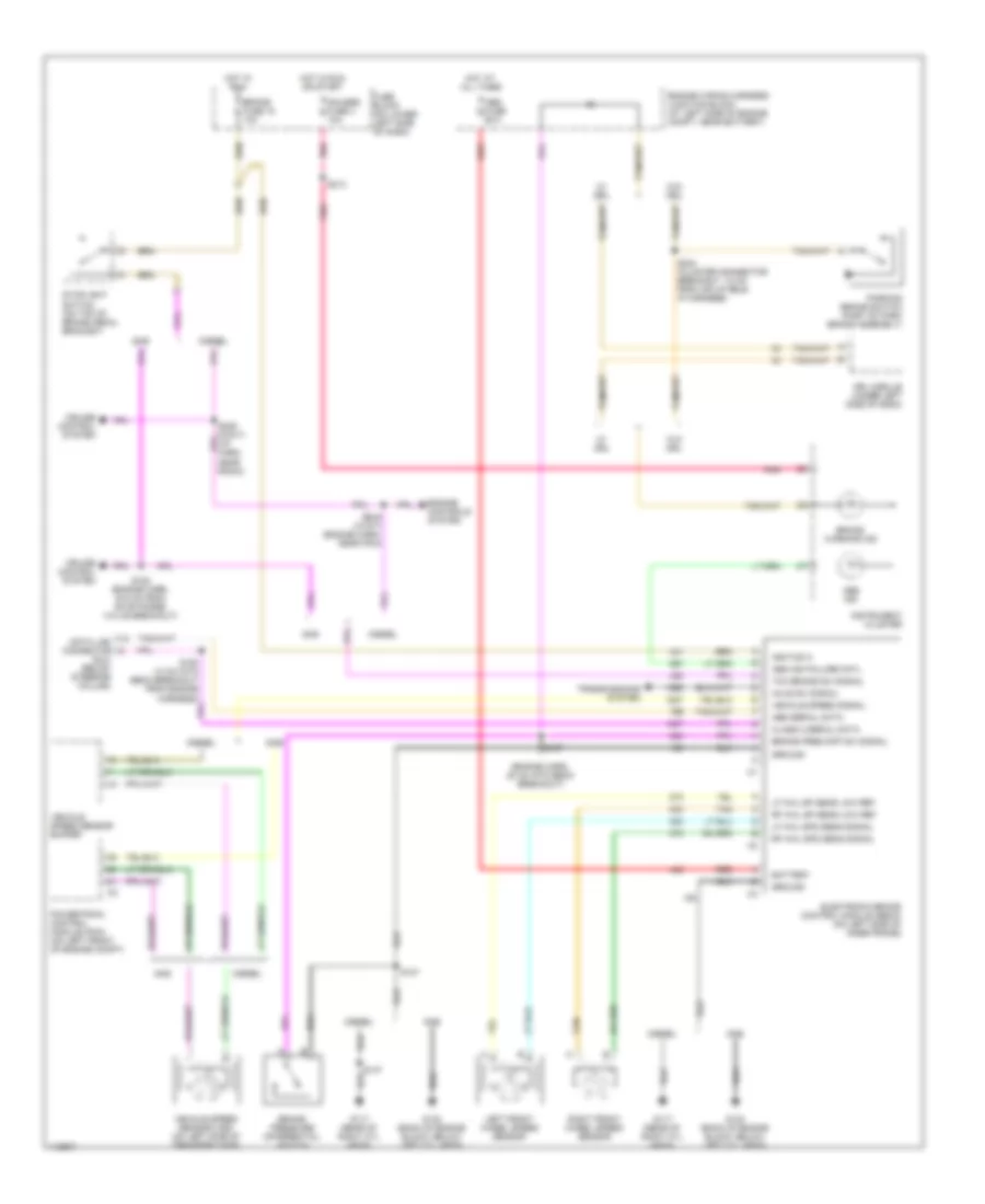
Compressor Wiring Diagram for GMC Cab & Chassis Sierra 2001 3500
 https://portal-diagnostov.com/license.html
Automotive Electricians Portal FZCO
Automotive Electricians Portal FZCO
https://portal-diagnostov.com/license.html
https://portal-diagnostov.com/license.html
Automotive Electricians Portal FZCO
Automotive Electricians Portal FZCO
List of elements for Compressor Wiring Diagram for GMC Cab & Chassis Sierra 2001 3500:
- 4.3l
- A/c compressor clutch
- A/c compressor clutch relay
- A/c fuse 10a
- A/c high pressure cutout switch (on a/c compressor)
- A/c high pressure recirculating switch (in a/c muffler hose)
- A/c low pressure cycling switch (on a/c compressor)
- A/c request
- A/c switch
- All others
- G100 (on left radiator support bracket)
- G110 (4.8l, 5.3l, 6.0l) (left front of engine)
- G119 (4.3l) (right front of engine)
- Hot at all times
- Hot in run or start
- Hvac control module
- Ign e fuse 10a
- Powertrain control module (pcm) (left front of engine compt)
- Press switch a/c high
- Relay ctrl a/c comp
- S101 (forward lamp harn)
- S102 (engine harn)
- Underhood junction block (left side of engine compt, near battery)
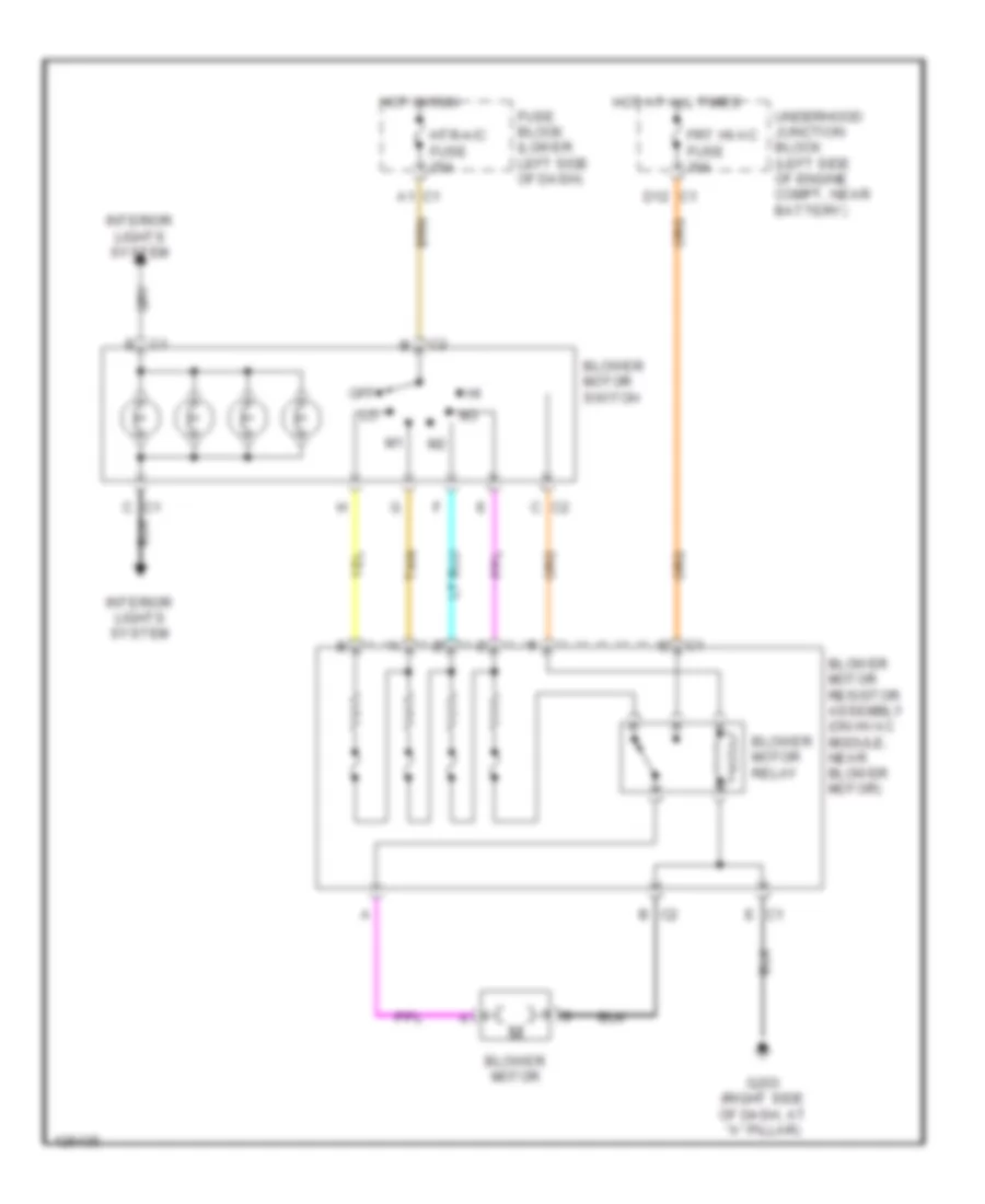
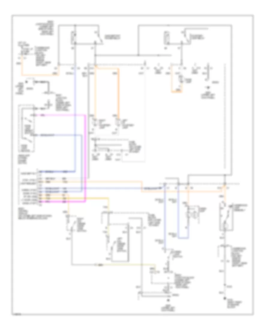
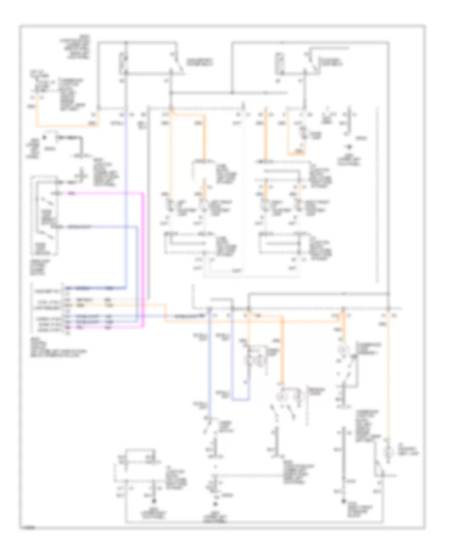
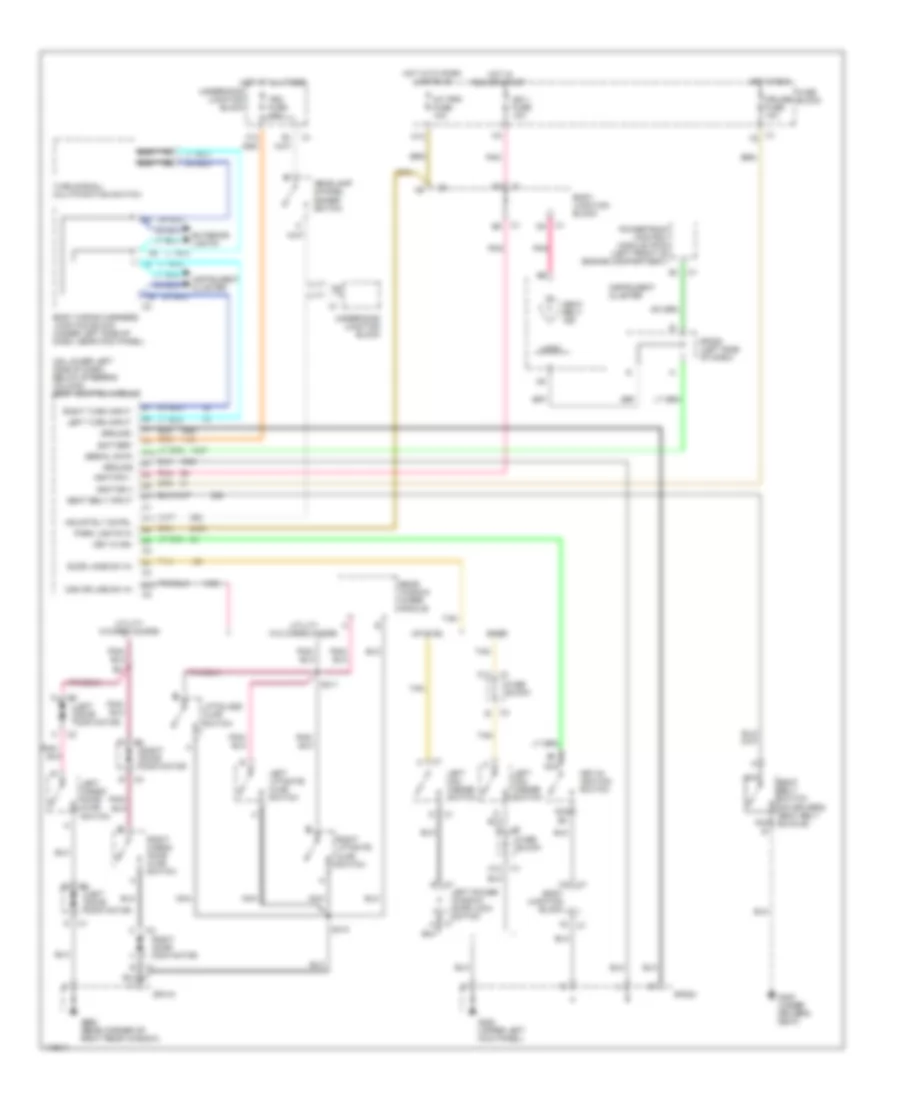
Heater Wiring Diagram for GMC Cab & Chassis Sierra 2001 3500
List of elements for Heater Wiring Diagram for GMC Cab & Chassis Sierra 2001 3500:
- Blower motor
- Blower motor relay
- Blower motor resistor assembly (on hvac module, near blower motor)
- Blower motor switch
- D12
- Frt hvac fuse 30a
- Fuse block (lower left side of dash)
- G203 (right side of dash, at "a" pillar)
- Hot at all times
- Hot in run
- Htr-a/c fuse 25a
- Interior lights system
- Off
- Tan
- Underhood junction block (left side of engine compt, near battery)
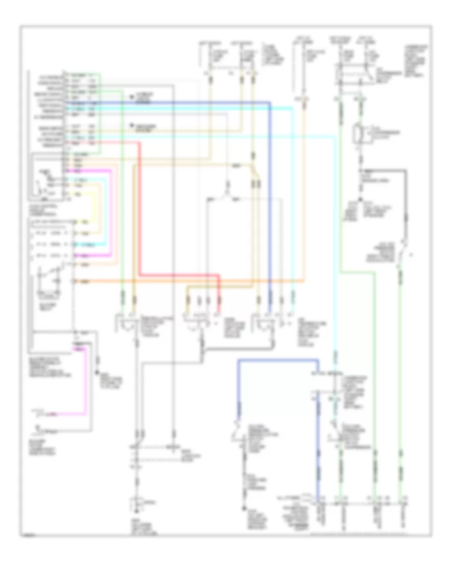
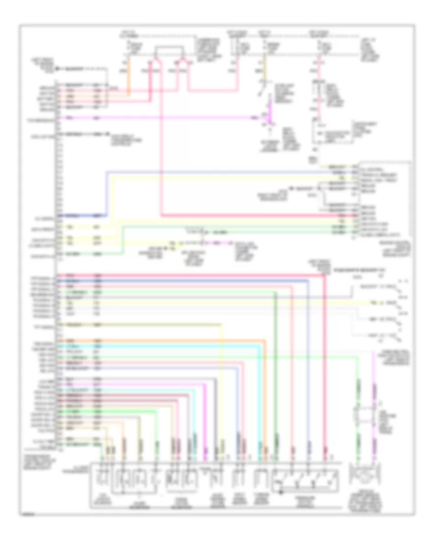
Manual A/C Wiring Diagram, Base for GMC Cab & Chassis Sierra 2001 3500
List of elements for Manual A/C Wiring Diagram, Base for GMC Cab & Chassis Sierra 2001 3500:
- 4.3l
- A a/c disable
- A/c comp relay ctrl
- A/c compressor clutch
- A/c compressor clutch relay
- A/c fuse 10a
- A/c high pressure cutout switch (on a/c compressor)
- A/c high pressure recirculating switch (in a/c muffler hose)
- A/c low pressure switch (right side of accumulator)
- A/c request
- A/c switch
- Air temperature actuator (bottom center of hvac module)
- All others
- B mode signal
- Blower motor (under right side of dash)
- Blower motor resistor/relay assembly (on hvac module, near blower motor)
- Blower relay
- Body junctioin block
- C ground
- D recirc signal
- D12
- Defogger system
- E illumination
- F temp signal
- Frt hvac fuse 30a
- Fuse block (lower left side of dash)
- G feedback
- G100 (on left radiator support bracket)
- G110 (4.8l, 5.3l, 6.0l) (left front of engine)
- G119 (4.3l) (right front of eng)
- G200 (on upper left dash at "a" pillar)
- G200 (right side of dash, at "a" pillar)
- H 5v reference
- High
- Hot at all times
- Hot in run
- Hot in run or start
- Htr-a/c fuse 25a
- Hvac 1 fuse 10a
- Hvac control module (under radio)
- Ign e fuse 10a
- Interior lights system
- J rear defog
- K ign power
- L a/c request
- Low
- M feedback
- Mode actuator (left side of hvac module)
- Off
- Powertrain control module (pcm) (left front of engine of engine compt)
- Press sw a/c high
- Recirculation actuator (top of hvac module)
- Red
- S101 (forward lamp harness)
- S102 (engine harn)
- Sp203
- Tan
- Underhood junctioin block (left side of engine compt, near battery)
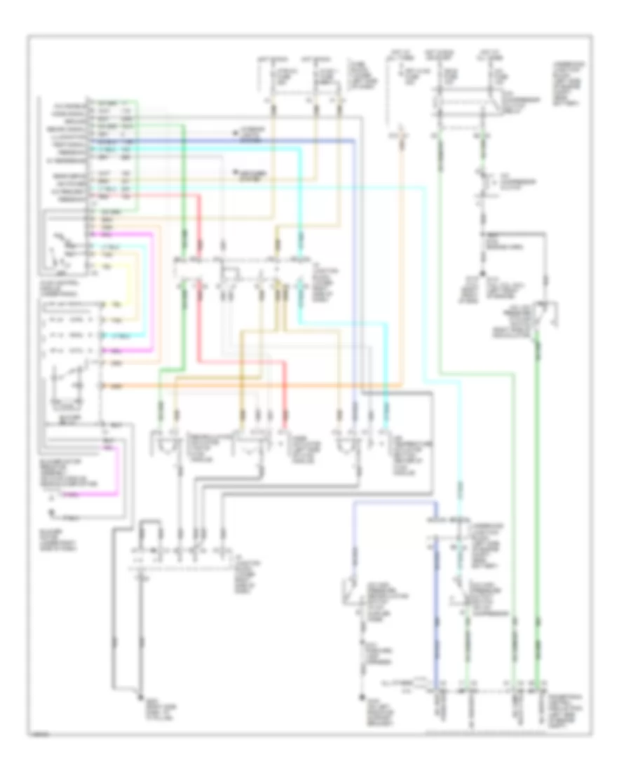
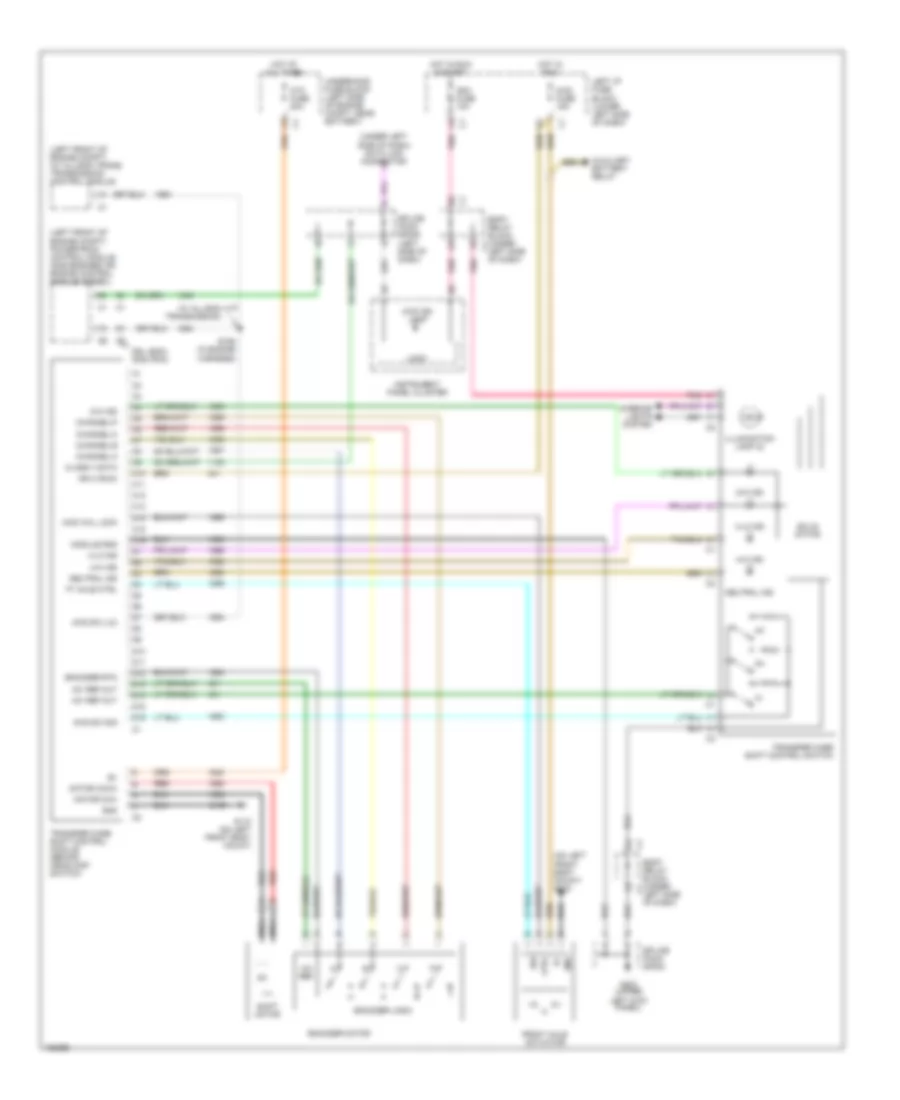
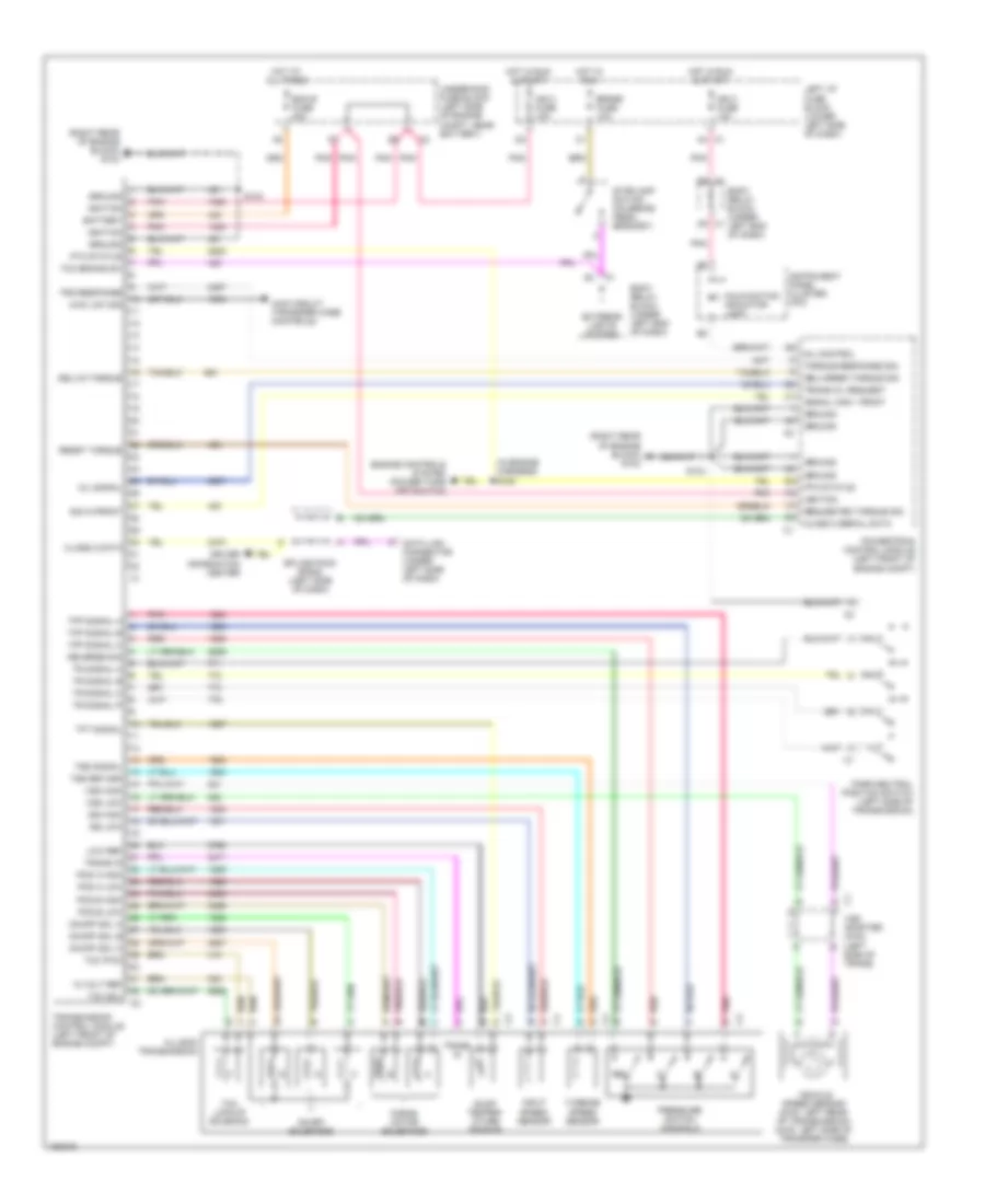
Manual A/C Wiring Diagram, Up Level for GMC Cab & Chassis Sierra 2001 3500
List of elements for Manual A/C Wiring Diagram, Up Level for GMC Cab & Chassis Sierra 2001 3500:
- 4.3l
- A a/c disable
- A/c compressor clutch
- A/c compressor clutch relay
- A/c fuse 10a
- A/c high press sw
- A/c high pressure cutout switch (on a/c compressor)
- A/c high pressure recirculating switch (in a/c muffler hose)
- A/c request
- A/c switch
- Air temperature actuator (bottom center of hvac module)
- All others
- B mode signal
- Blower motor (under right side of dash)
- Blower motor resistor assembly (on hvac module, near blower motor)
- Blower relay
- C ground
- C3 c3
- D recirc signal
- D12
- Defogger system
- E illumination
- F temp signal
- Frt hvac fuse 30a
- Fuse block (lower left side of dash)
- G feedback
- G100 (on left radiator support bracket)
- G110 (4.8l, 5.3l, 6.0l) (left front of engine)
- G119 (4.3l) (right front of eng)
- G203 (right side dash, at "a" pillar)
- H 5v reference
- Hot at all times
- Hot in run
- Hot in run or start
- Htr-a/c fuse 25a
- Hvac 1 fuse 10a
- Hvac control module (under radio)
- I/p junction block (lower right side of dash)
- Ign e fuse 10a
- Interior lights system
- J rear defog
- K ign power
- L a/c request
- M feedback
- Mode actuator (left side of hvac module)
- Off
- Powertrain control module (pcm) (left side of engine compt)
- Recirculation actuator (top of hvac module)
- Red
- Relay ctrl a/c comp
- S101 (forward lamp harness)
- S102 (engine harn)
- Tan
- Underhood junctioin block (left side of engine compt, near battery)
ANTI-LOCK BRAKES
Anti-lock Brake Wiring Diagrams for GMC Cab & Chassis Sierra 2001 3500
List of elements for Anti-lock Brake Wiring Diagrams for GMC Cab & Chassis Sierra 2001 3500:
- (dlc) (below steering column)
- (engine harn, 20 cm into ebcm breakout)
- Abs fuse 60a
- Abs ind
- Abs ind failure cntl
- Abs serial data
- Axle sw signal
- Battery
- Brake fuse 18 10a
- Brake pres diff sw signal
- Brake pressure differential switch
- Brake warning ind
- Class 2 serial data
- Cruise control system
- Data link connector
- Diesel
- Drl module (under left side of dash)
- Electronic brake control module (ebcm) (on left side of inner frame)
- Engine controls system
- Engine wiring harness junction block (at left side of engine compt, near battery)
- Fuse block (on lower left side of dash)
- G117 (rear of right cyl head)
- G132 (back of engine block, below left cyl head)
- Gas
- Gauges fuse 4 10a
- Ground
- Hot at all times
- Hot in run
- Hot in run or start
- Ignition 3
- Instrument cluster
- Left front wheel speed sensor
- Lf whl sp sens low ref
- Lf whl spd sens signal
- Parking brake switch (part of park brake assembly)
- Pnk
- Powertrain control module (pcm) (on left front of engine compt)
- Red
- Rf whl sp sens low ref
- Rf whl spd sens signal
- Right front wheel speed sensor
- S107
- S150 (13 cm into ebcm breakout from engine harness)
- S152 (engine harn, 16.5 cm from evap purge valve breakout)
- S157
- S213
- S224 (cluster connector breakout, 12 cm from inflatable ip harness)
- S229 (w/a/t) (engine harn, near pcm)
- S229 (w/m/t) (i/p harn, near radio)
- Stoplight switch (on top of brake pedal bracket)
- Tan
- Tcc brake sw signal
- Transmissions system
- Vehicle speed sensor (vss) (on left side of transfer case)
- Vehicle speed sensor buffer
- Vehicle speed signal
- W/ drl
- W/o drl
ANTI-THEFT
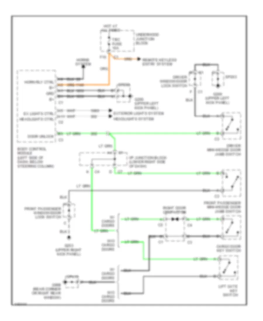
Forced Entry Wiring Diagram for GMC Cab & Chassis Sierra 2001 3500
List of elements for Forced Entry Wiring Diagram for GMC Cab & Chassis Sierra 2001 3500:
- (left side of dash, below steering column)
- A11
- All times
- Body control module
- Cargo door key switch
- Door unlock
- Driver mini-wedge door jamb switch
- Driver window/door lock switch
- Ex lights ctrl
- Exterior lights system
- F10
- Front passenger mini-wedge door jamb switch
- Front passenger window/door lock switch
- G200 (upper left kick panel)
- G203 (upper right kick panel)
- G998 (rear corner or right rear window)
- Grd
- Headlights ctrl
- Headlights system
- Horn rly ctrl
- Horns system
- Hot at
- I/p junction block (lower right side of dash)
- Lift gate key switch
- Remote keyless entry system
- Right door contactor
- Sp203
- Sp410
- Tbc fuse 10a
- Underhood junction block
- W/ cargo doors
- W/o cargo doors
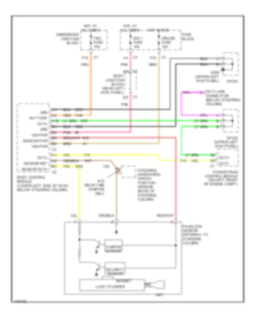
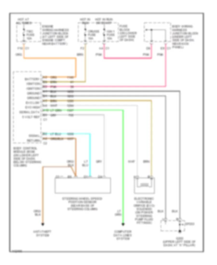
Passlock Wiring Diagram for GMC Cab & Chassis Sierra 2001 3500
List of elements for Passlock Wiring Diagram for GMC Cab & Chassis Sierra 2001 3500:
- A12
- Battery
- Body control module (lower left side of dash below steering column)
- Body junction block (near left kick panel)
- Connector (below steering column)
- Cruise fuse 10a
- Data
- Data link
- F10
- Fuse block
- G200 (upper left kick panel)
- Grd
- Hot at all times
- Hot in run
- Ign 1 fuse 10a
- Ign pwr
- Key
- Lock cylinder
- Magnet
- Passlock sensor (internal to steering column)
- Pnk
- Powertrain control module (on left front of engine compt)
- Security sensor
- Sensor data
- Sensor pwr
- Sensor ret
- Sp203
- Sp203 (upper left kick panel)
- Steering handwheel speed/ position sensor (base of steering column)
- Tamper sensor
- Tbc fuse 10a
- Underhood junction block
- W/o rear time damping only
BODY COMPUTER
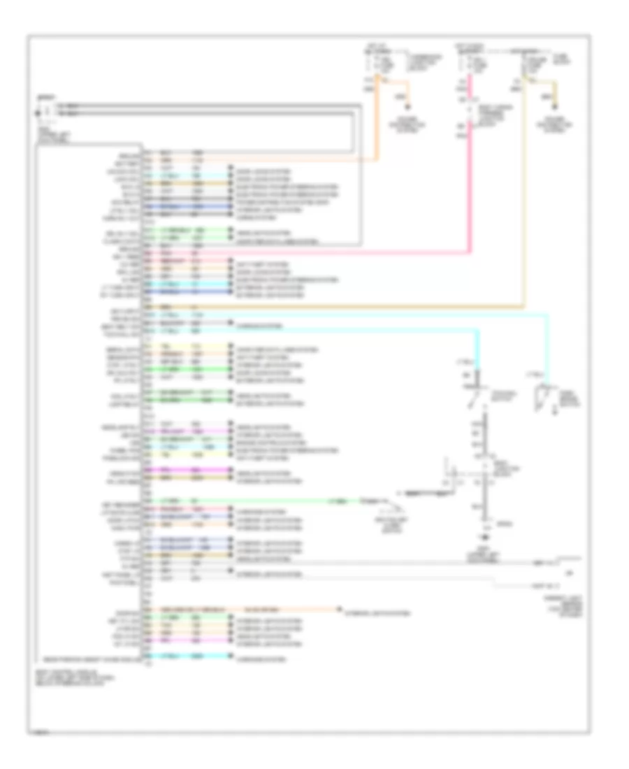
Body Computer Wiring Diagrams for GMC Cab & Chassis Sierra 2001 3500
List of elements for Body Computer Wiring Diagrams for GMC Cab & Chassis Sierra 2001 3500:
- 12v ref
- 54 (54 or 394)
- 5v ref
- A10
- A11
- A12
- Acc relay
- Ambient light sensor (top center of dash)
- Anti-theft system
- B10
- B11
- B12
- Battery
- Body control module (on lower left side of dash, below steering column)
- Body junction block
- Body wiring harness junction block
- Cargo lp
- Class 2 data
- Computer data lines system
- Cruise fuse 10a
- Ctsy lp
- Ctsy lp rly
- Door latch
- Door locks system
- Door sw
- Dr unlk rly
- Drl rly coil
- Electronic power steering system
- Engine controls system
- Evo hi
- Evo lo
- Exterior lights system
- F10
- Fog lp rly
- Fog lp sw
- Ftp sw
- Fuse block
- G200 (upper left kick panel)
- Ground
- Headlamp rly
- Headlights system
- Headlp dim
- Horn rly out
- Horns system
- Hot at all times
- Hot in run
- Hot in run & start
- Ign 1 feed
- Ign 1 fuse 10a
- Ign 3 input
- Ignition key alarm switch
- Inadv pwr
- Inst panel lp
- Int lp sw
- Interior lights system
- Key cyl sw
- Key reminder
- Lamp relay
- Led dim
- Lf dr sw
- Liftgate ajar
- Lock coil
- Lp rly coil
- Lt turn input
- Nca
- Park brake switch
- Passlock sig
- Photocell
- Pk lp rly
- Pk lps feed
- Pnk
- Power distribution system
- Power distribution system (rap)
- Prk bk sw
- Rear parking assist chime module
- Rfa link
- Rt turn input
- Seat belt sw
- Sensor rtn
- Serial data
- Sp203
- Tan
- Tbc fuse 10a
- Tow/haul sw
- Tow/haul switch
- Underhood junction block
- Unlock coil
- Vss
- Warning system
- Warnings system
- Wheel pos
COMPUTER DATA LINES
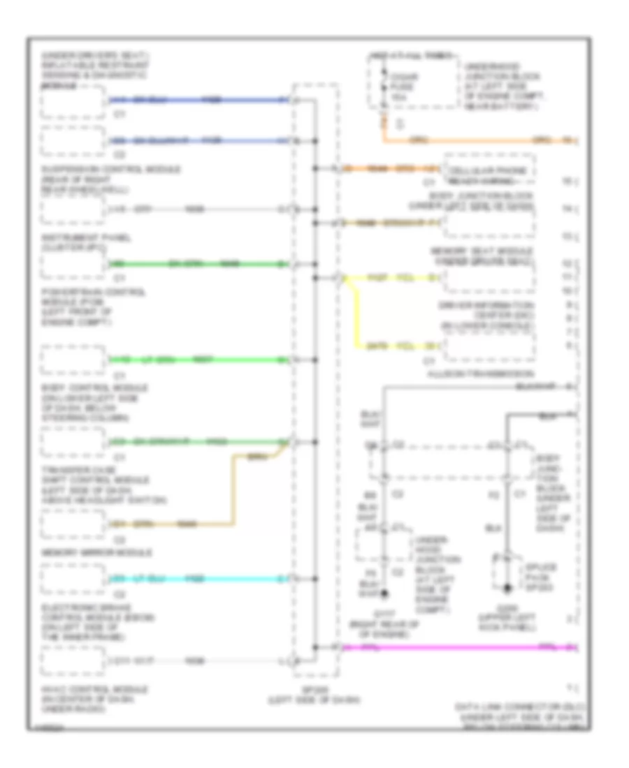
Computer Data Lines for GMC Cab & Chassis Sierra 2001 3500
List of elements for Computer Data Lines for GMC Cab & Chassis Sierra 2001 3500:
- (under driver's seat) inflatable restraint sensing & diagnostic module
- A12
- Allison transmission
- Body control module (on lower left side of dash, below steering column)
- Body junc- tion block (under left side of dash)
- Body junction block (under left side of dash)
- C11
- Cellular phone ready wiring
- Cigar fuse 15a
- Data link connector (dlc) (under left side of dash, below steering column)
- Driver information center (dic) (in lower console)
- Electronic brake control module (ebcm) (on left side of the inner frame)
- G117 (right rear of of engine)
- G200 (upper left kick panel)
- Hot at all times
- Hvac control module (in center of dash, under radio)
- Instrument panel cluster (ipc)
- Memory mirror module
- Memory seat module (under driver seat)
- Powertrain control module (pcm) (left front of engine compt)
- Sp205 (left side of dash)
- Splice pack sp203
- Suspension control module (rear of right rear wheelwell)
- Transfer case shift control module (left side of dash, above headlight switch)
- Under- hood junction block (at left side of engine compt)
- Underhood junction block (at left side of engine compt, near battery)
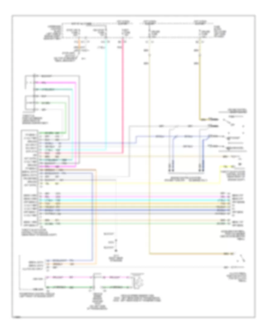
CRUISE CONTROL
6.0L
6.0L VIN U, Cruise Control Wiring Diagram for GMC Cab & Chassis Sierra 2001 3500
List of elements for 6.0L VIN U, Cruise Control Wiring Diagram for GMC Cab & Chassis Sierra 2001 3500:
- (36 series only)
- (power take off)
- 5 volt ref
- A12
- A13
- A14
- A15
- Accelerator pedal position sensor (above accelerator pedal)
- Act cntrl
- App sens
- App sens 1
- App sens 2
- App sens 3
- App sense
- C1 d11
- C2 a10
- Clutch pedal position switch (top of clutch pedal)
- Clutch sw input
- Cruise control on/off switch
- Cruise fuse 10a
- Cruise req
- Ect fuse 15a
- Engine compt)
- Engine controls system
- F12
- Fuse block (on lower left side of dash)
- G117 (right rear of engine)
- Ground
- Hot at all times
- Hot in run & start
- Ign
- Nca
- Off
- Pnk
- Powertrain control module (left front of engine compt)
- R/a input
- Resume/accel
- S/c input
- S103
- Sens 1 grd
- Sens 1 rt
- Sens 2 grd
- Sens 2 rt
- Sens 3 grd
- Sens 3 rt
- Serial data
- Set/coast
- Stop lps fuse 20a
- Stoplamp switch (on top of brake pedal bracket)
- Stp lp in
- Tan
- Throttle actuator control (tac) module (near front of engine compt)
- Throttle actuator control motor (near front of
- Throttle position sensor (near front of engine compartment)
- Tp sens 1
- Tp sens 2
- Underhood junction block (left side of engine compt, near battery)
- Veh stop fuse 10a
- Vehicle speed sensor (vss) (2wd: left rear side of transmission) (4wd: left rear side of transfer case)
- Vehicle speed sensor adapter (4wd) (on left side of transmission)
- Vss high
- Vss low
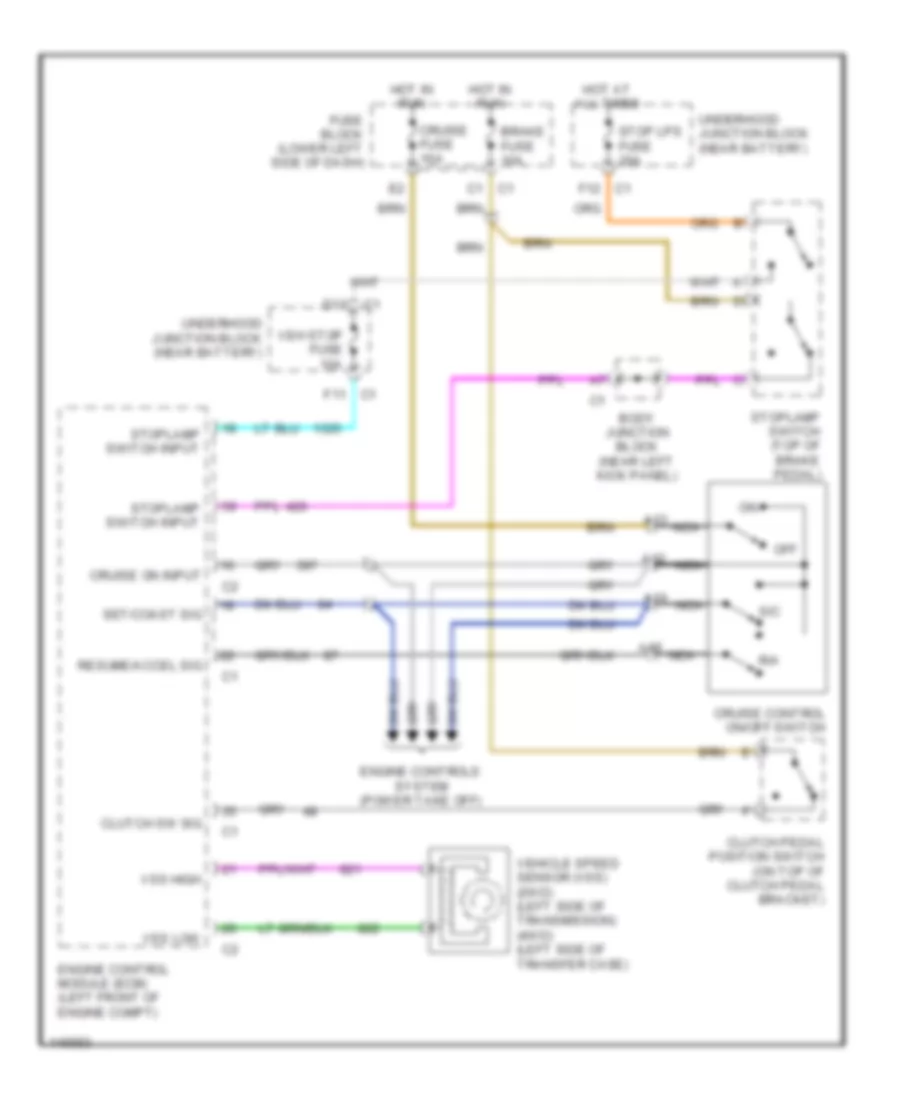
6.6L
6.6L VIN 1, Cruise Control Wiring Diagram for GMC Cab & Chassis Sierra 2001 3500
List of elements for 6.6L VIN 1, Cruise Control Wiring Diagram for GMC Cab & Chassis Sierra 2001 3500:
- A12
- A13
- A14
- A15
- Body junction block (near left kick panel)
- Brake fuse 10a
- C1 c1
- C1 f12
- Clutch pedal position switch (on top of clutch pedal bracket)
- Clutch sw sig
- Cruise control on/off switch
- Cruise fuse 10a
- Cruise on input
- D11
- Engine control module (ecm) (left front of engine compt)
- Engine controls system (power take off)
- F11 c1
- Fuse block (lower left side of dash)
- Hot at all times
- Hot in run
- Nca
- Off
- R/a
- Resume/accel sig
- S/c
- Set/coast sig
- Stop lps fuse 20a
- Stoplamp switch (top of brake pedal)
- Stoplamp switch input
- Underhood junction block (near battery)
- Veh stop fuse 10a
- Vehicle speed sensor (vss) (2wd) (left side of transmission) (4wd) (left side of transfer case)
- Vss high
- Vss low
8.1L
8.1L VIN G, Cruise Control Wiring Diagram for GMC Cab & Chassis Sierra 2001 3500
List of elements for 8.1L VIN G, Cruise Control Wiring Diagram for GMC Cab & Chassis Sierra 2001 3500:
- (36 series only)
- (power take off)
- 5 volt ref
- A12
- A13
- A14
- A15
- Accelerator pedal position sensor (above accelerator pedal)
- Act cntrl
- App sens
- App sens 1
- App sens 2
- App sens 3
- App sense
- C1 d11
- C2 a10
- Clutch pedal position switch (top of clutch pedal)
- Clutch sw input
- Cruise control on/off switch
- Cruise fuse 10a
- Cruise req
- Ect fuse 15a
- Engine compt)
- Engine controls system
- F12
- Fuse block (on lower left side of dash)
- G117 (right rear of engine)
- Ground
- Hot at all times
- Hot in run & start
- Ign
- Nca
- Off
- Pnk
- Powertrain control module (left front of engine compt)
- R/a input
- Resume/accel
- S/c input
- S103
- Sens 1 grd
- Sens 1 rt
- Sens 2 grd
- Sens 2 rt
- Sens 3 grd
- Sens 3 rt
- Serial data
- Set/coast
- Stop lps fuse 20a
- Stoplamp switch (on top of brake pedal bracket)
- Stp lp in
- Tan
- Throttle actuator control (tac) module (near front of engine compt)
- Throttle actuator control motor (near front of
- Throttle position sensor (near front of engine compartment)
- Tp sens 1
- Tp sens 2
- Underhood junction block (left side of engine compt, near battery)
- Veh stop fuse 10a
- Vehicle speed sensor (vss) (2wd: left rear side of transmission) (4wd: left rear side of transfer case)
- Vehicle speed sensor adapter (4wd) (on left side of transmission)
- Vss high
- Vss low
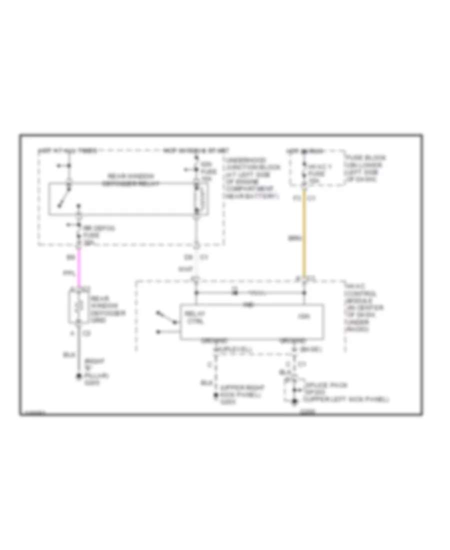
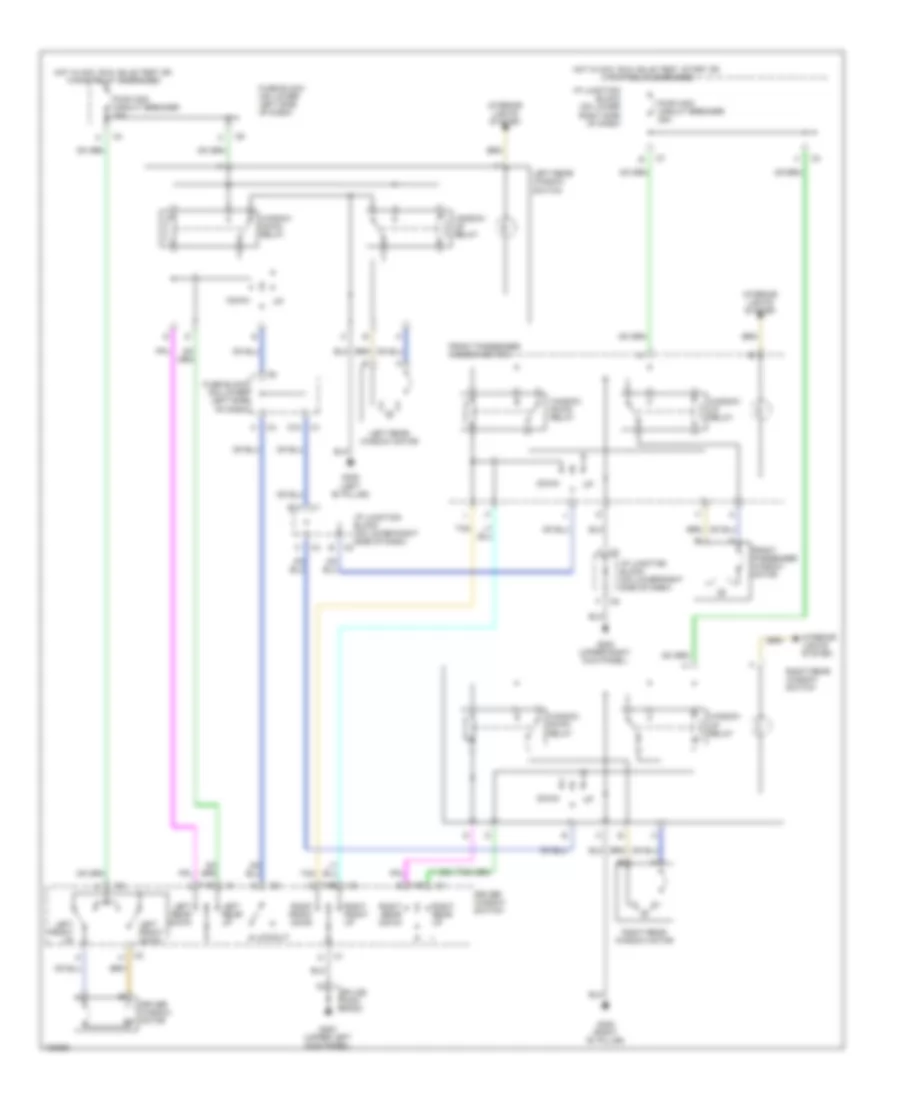
DEFOGGERS
Defogger Wiring Diagram for GMC Cab & Chassis Sierra 2001 3500
List of elements for Defogger Wiring Diagram for GMC Cab & Chassis Sierra 2001 3500:
- (base)
- (right "b" pillar) g305
- (uplevel)
- (upper right kick panel) g203
- A c1
- A c2
- C c1
- D9 c1
- F3 c1
- Fuse block (on lower left side of dash)
- G200
- Ground
- Hot at all times
- Hot in run
- Hot in run & start
- Hvac 1 fuse 10a
- Hvac control module (in center of dash, under radio)
- Ign
- Ign fuse 10a
- Ind
- K c1
- Rear window defogger grid
- Rear window defogger relay
- Relay ctrl
- Rr defog fuse 30a
- Splice pack sp203 (upper left kick panel)
- Underhood junction block (at left side of engine compartment, near battery)
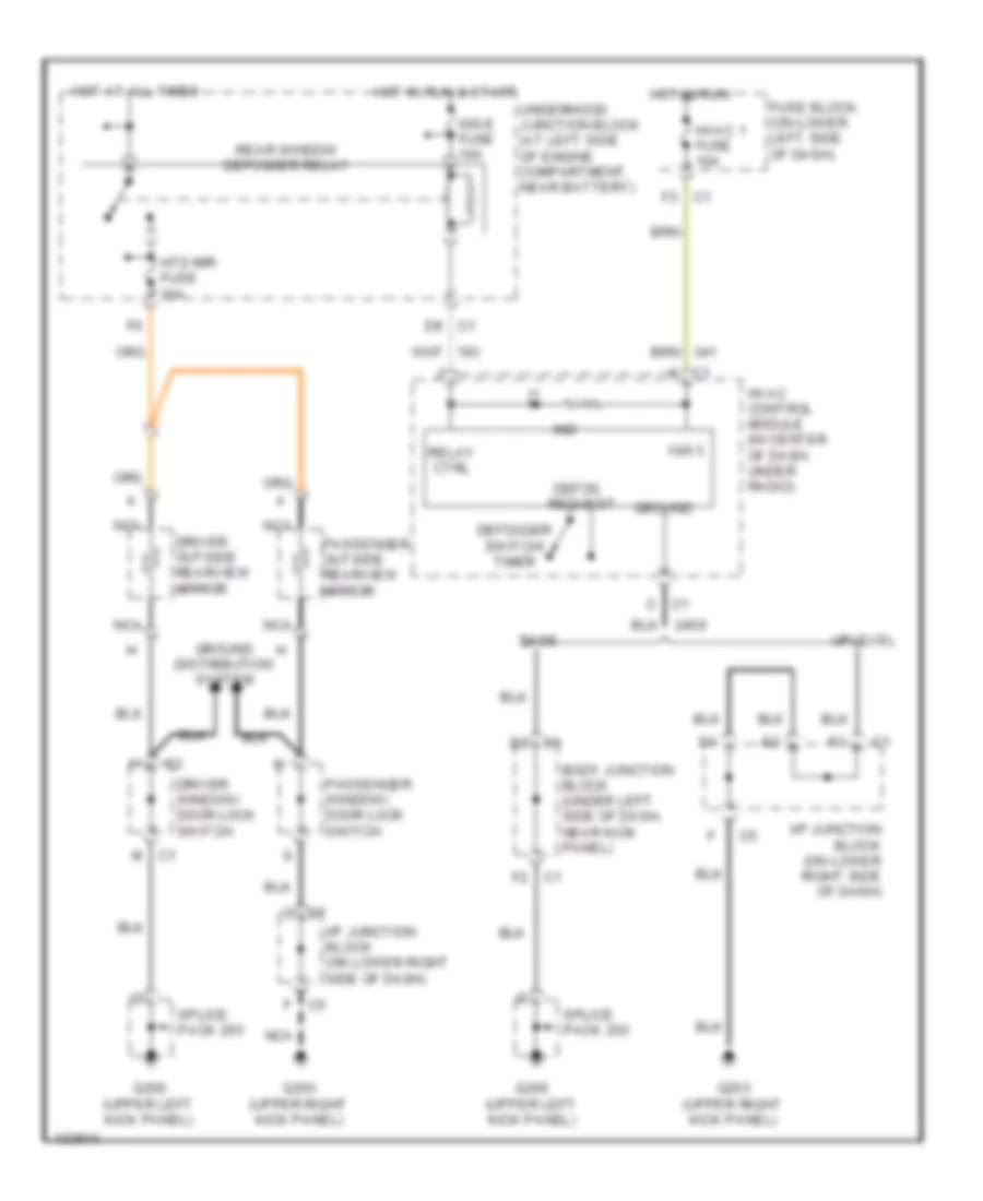
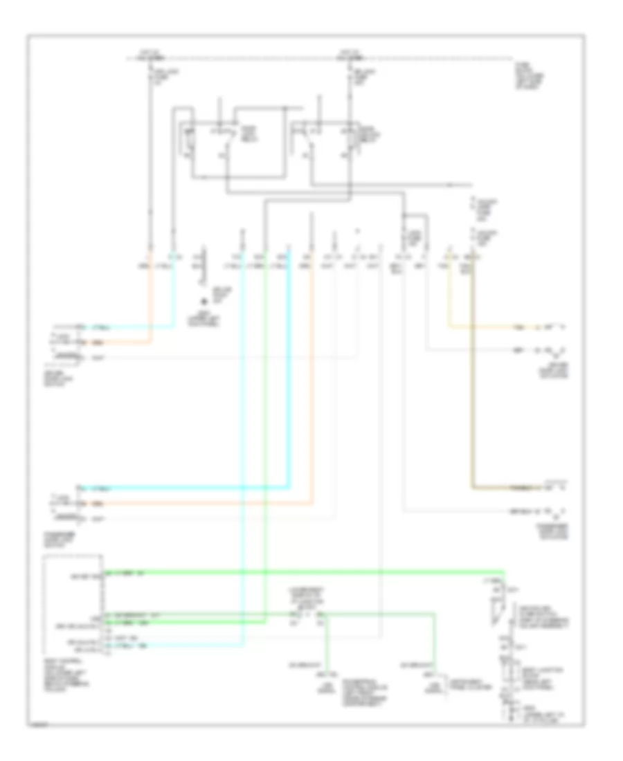
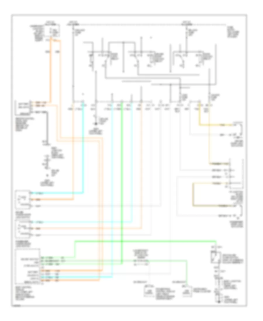
Heated Mirrors Wiring Diagram for GMC Cab & Chassis Sierra 2001 3500
List of elements for Heated Mirrors Wiring Diagram for GMC Cab & Chassis Sierra 2001 3500:
- Base
- Body junction block (under left side of dash, near kick panel)
- C c7
- C1 c
- C1 f2
- D2 c1
- D9 c1
- Defog request
- Defogger switch/ timer
- Driver outside rearview mirror
- Driver window/ door lock switch
- F c5
- F3 c1
- Fuse block (on lower left side of dash)
- G200 (upper left kick panel)
- G203 (upper right kick panel)
- Ground
- Ground distribution system
- Hot at all times
- Hot in run
- Hot in run & start
- Htd mir fuse 10a
- Hvac 1 fuse 10a
- Hvac control module (in center of dash, under radio)
- I/p junction block (on lower right side of dash)
- Ign 3
- Ign e fuse 10a
- Ind
- K c1
- M c1
- Nca
- Passenger outside rearview mirror
- Passenger window/ door lock switch
- Rear window defogger relay
- Relay ctrl
- Splice pack 203
- Underhood junction block (at left side of engine compartment, near battery)
- Uplevel
ELECTRONIC POWER STEERING
Electronic Power Steering Wiring Diagram for GMC Cab & Chassis Sierra 2001 3500
List of elements for Electronic Power Steering Wiring Diagram for GMC Cab & Chassis Sierra 2001 3500:
- 5 volt ref
- A12
- A4 c1
- Anti-theft system
- Battery
- Body control module (bcm) (on lower left side of dash, below steering column)
- Body wiring harness junction block (under left side of dash, near kick panel)
- Computer data lines system
- Cruise fuse 10a
- E9 c1
- Electronic variable orifice (evo) solenoid (on power steering pump fluid fittings)
- Engine wiring harness junction block (at left side of engine compt, near battery)
- Evo high
- Evo low
- F10 c1
- Fuse block (on lower left side of dash)
- G202 (upper left side of dash, at "a" pillar)
- Ground
- Hot at all times
- Hot in run
- Hot in run or start
- Ign 1 fuse 10a
- Ignition
- Pnk
- Return
- Serial data
- Signal
- Sp203
- Steering wheel speed/ position sensor (near base of steering column)
- Tbc fuse 10a
ENGINE PERFORMANCE
6.0L
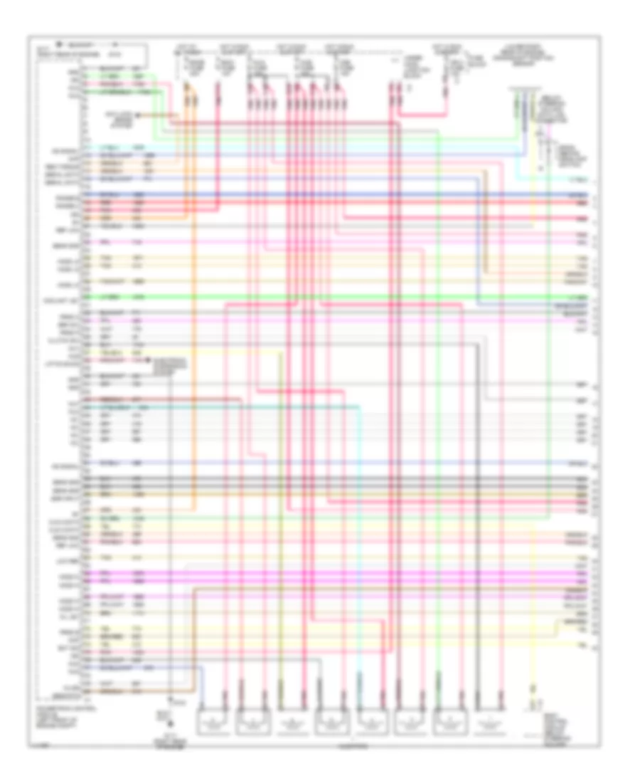
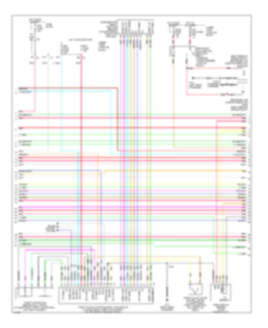
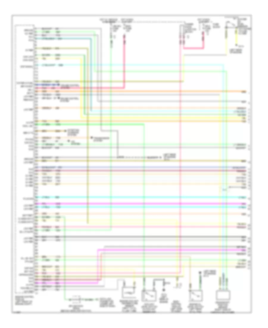
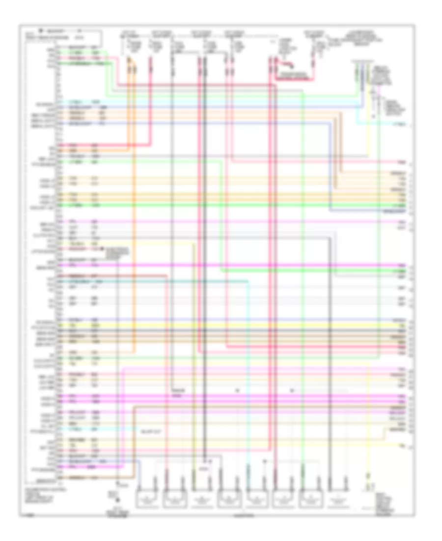
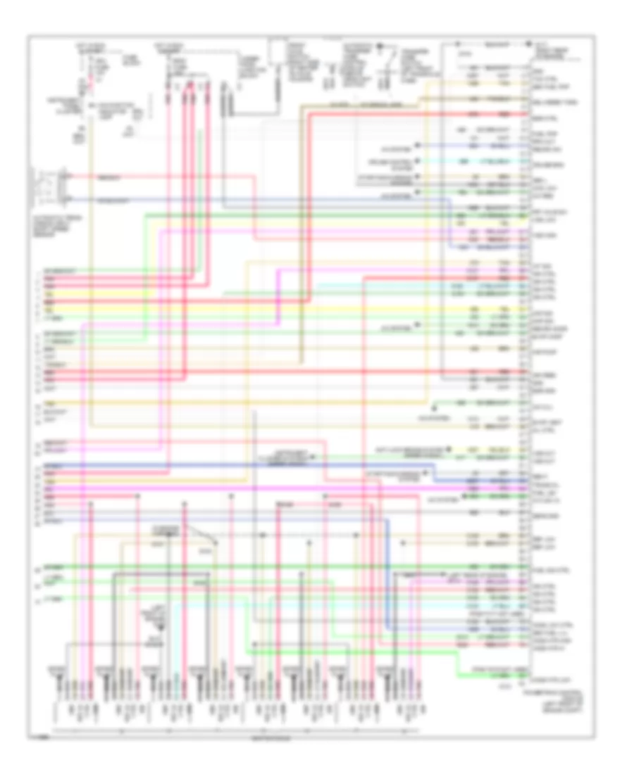
6.0L VIN U, Engine Performance Wiring Diagrams (1 of 5) for GMC Cab & Chassis Sierra 2001 3500
List of elements for 6.0L VIN U, Engine Performance Wiring Diagrams (1 of 5) for GMC Cab & Chassis Sierra 2001 3500:
- (below steering column) data link connector
- (lower right rear of engine) crankshaft position sensor
- +5v
- 3-2 ss
- Anti-lock brake system
- Body control module (below steering column)
- Brk sw
- C10
- C11
- C12
- Ckp
- Cls 2 data
- Clutch sw
- Cmp
- Coolant lev
- D10
- E12
- Ecm1 fuse 10a
- Ecmb fuse 20a
- Ect sig
- Egr input
- Electronic suspension system
- Fuse block
- G117 (right rear of engine)
- Gnd
- Ho2s hi
- Ho2s lo
- Hot at all times
- Hot in run & start
- Ign
- Ign 0 fuse 10a
- Inj1
- Inj2
- Inj3
- Inj4
- Inj5
- Inj6
- Inj7
- Inj8
- Inja fuse 15a
- Injb fuse 15a
- Injectors
- Ks signal
- Lift/dive sig
- Low ref
- O2b fuse 15a
- Oil lev
- Pnk
- Pnk b
- Powertrain control module (left front of engine compt)
- Prnd a
- Prnd b
- Prnd p
- Range b
- Range c
- Red
- Ref low
- Req torque
- S103
- Sens gnd
- Sens rtn
- Serial data
- Sp205 (behind headlamp switch)
- Tan
- Under- hood junction block
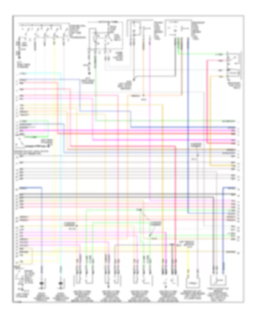
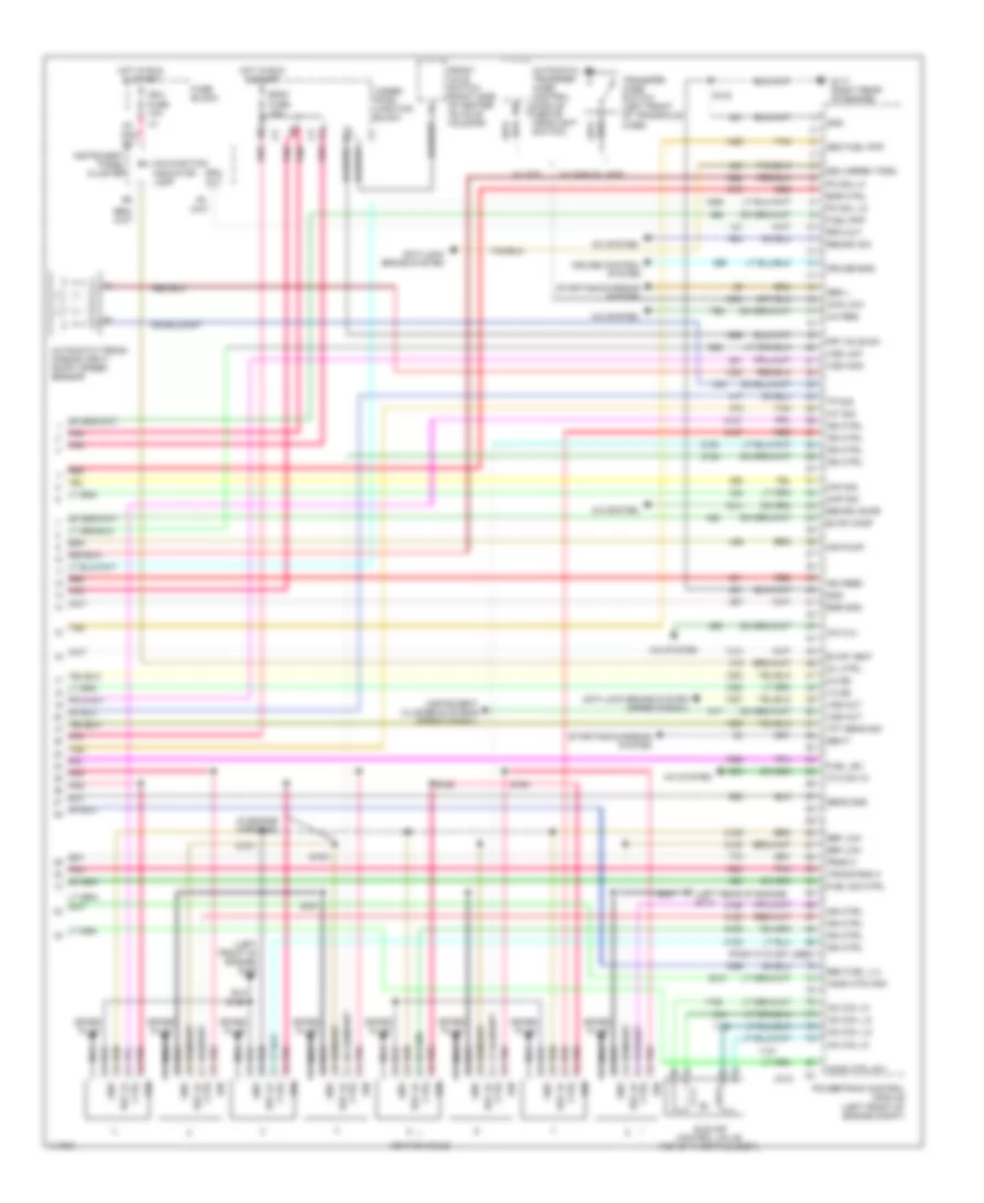
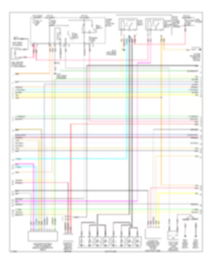
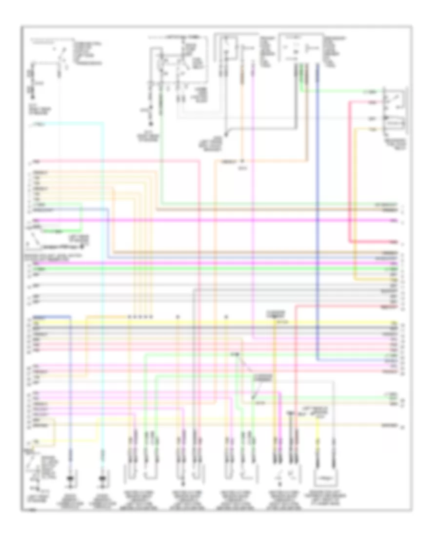
6.0L VIN U, Engine Performance Wiring Diagrams (2 of 5) for GMC Cab & Chassis Sierra 2001 3500
List of elements for 6.0L VIN U, Engine Performance Wiring Diagrams (2 of 5) for GMC Cab & Chassis Sierra 2001 3500:
- (in engine harness)
- (left front of engine)
- (left rear of engine)
- (left rear of engine) g114
- (not used)
- Ecm b fuse 20a
- Engine coolant level switch (in coolant reservoir)
- Engine coolant temperature sensor (left front of cylinder head)
- Engine oil level switch (right side of oil pan)
- Fuel pump relay
- G104
- G110
- G117 (right rear of engine)
- G402 (left frame body mount bracket)
- Heated oxygen sensor (bank 1 sensor 1) (left exh pipe before converter)
- Heated oxygen sensor (bank 1 sensor 2) (left exh pipe after converter)
- Heated oxygen sensor (bank 2 sensor 1) (right exh pipe before converter)
- Heated oxygen sensor (bank 2 sensor 2) (right exh pipe after converter)
- Hot at all times
- Knock sensor 1 (under intake manifold)
- Knock sensor 2 (under intake manifold)
- Nca
- Park/neutral position switch (left side of transmission)
- Pnk
- Primary fuel pump/ level sensor (in fuel tank)
- Red
- S103
- S104
- S113
- S114a
- S115
- S116
- S312
- Secondary fuel pump relay
- Secondary fuel pump/ level sensor (in fuel tank)
- Tan
- Throttle position sensor (w/o electronic throttle control) (on throttle body assy)
- Under- hood junction block
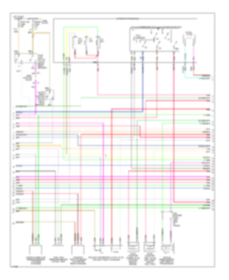
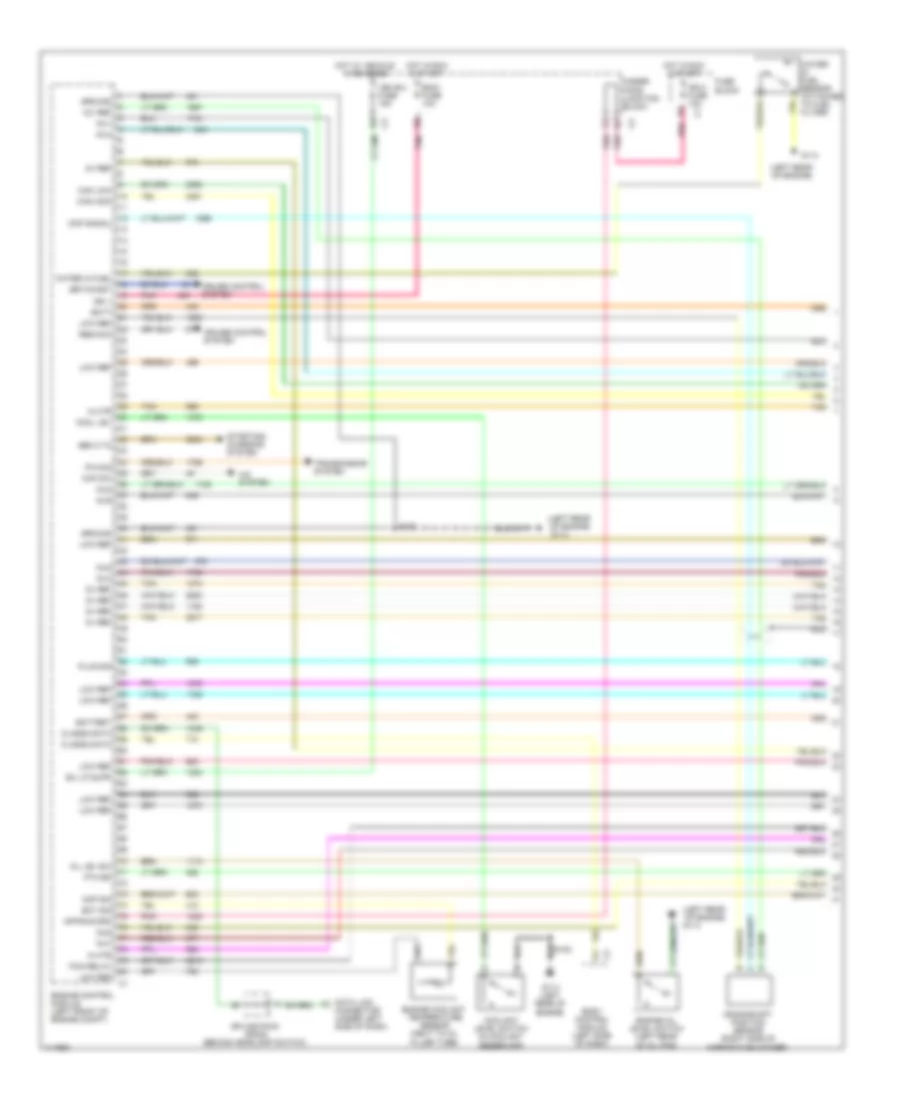
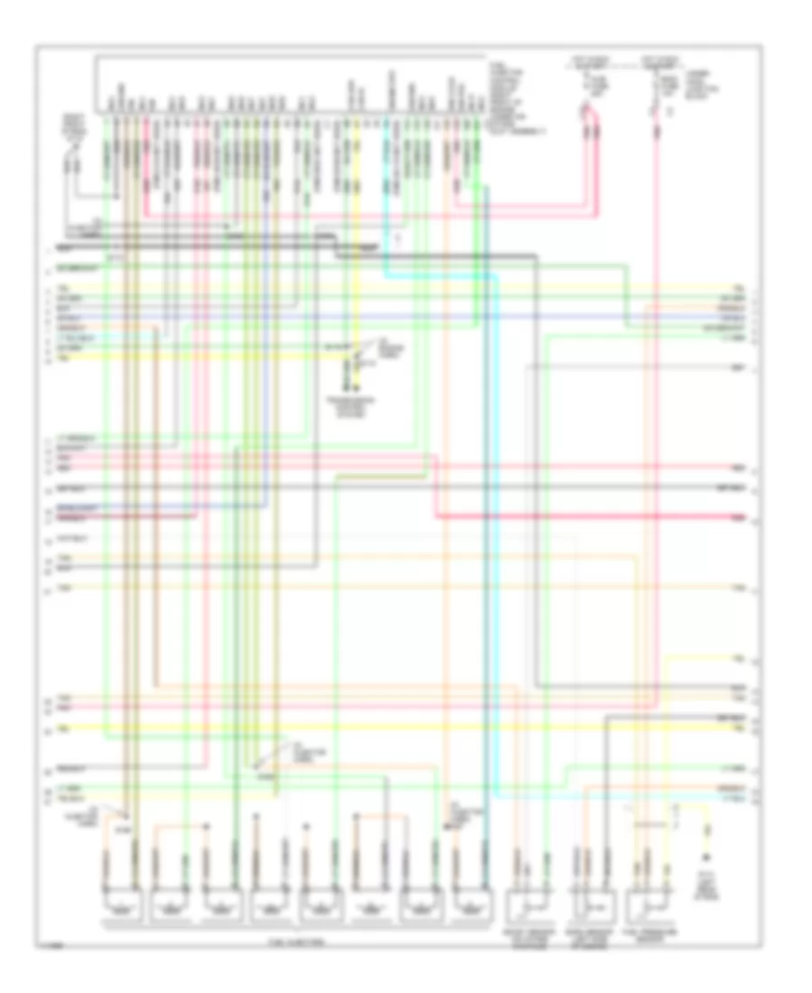
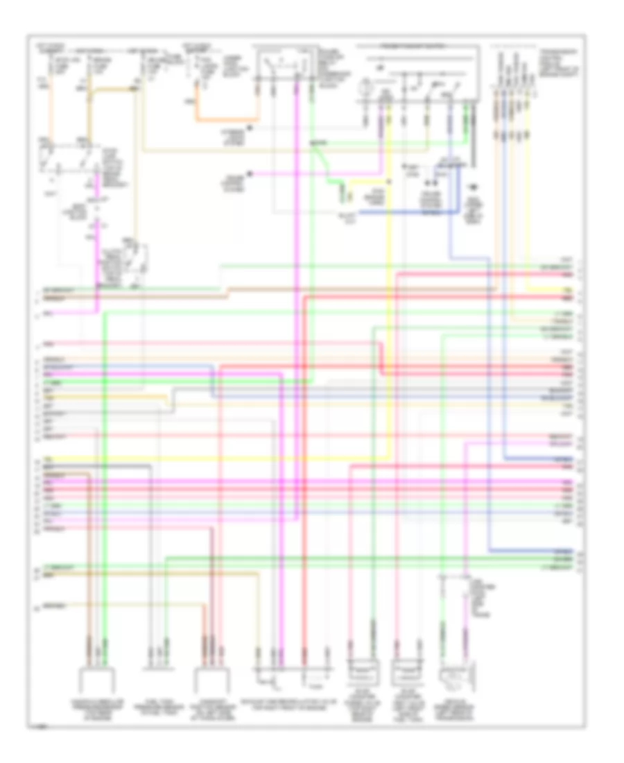
6.0L VIN U, Engine Performance Wiring Diagrams (3 of 5) for GMC Cab & Chassis Sierra 2001 3500
List of elements for 6.0L VIN U, Engine Performance Wiring Diagrams (3 of 5) for GMC Cab & Chassis Sierra 2001 3500:
- 1-2 sol
- 2-3 sol
- A/t fluid pressure manual valve position switch
- Automatic transaxle
- Body junction block
- Brake fuse 10a
- Camshaft position sensor (top center rear of engine)
- Clutch pedal position switch (top of pedal bracket)
- Evap canister purge valve (top right rear of engine)
- Evap canister vent valve (left front side of fuel tank)
- Exhaust gas recirculation valve (top right front of engine)
- F12
- Fuel tank pressure sensor (in fuel tank)
- Fuse block
- Hot in run
- Hot in run & start
- Manifold absolute pressure sensor (top rear of engine)
- N pnk
- P red
- Pc sol valve
- Pnk
- Pnk a
- Pnk b
- Red
- Red e
- Red/
- Rev
- Stop lps fuse 20a
- Stop- lamp switch (top of brake pedal bracket)
- Tan
- Tcc pwm sol
- Tft sensor
- Vehicle speed sensor (left rear of transmission)
- Vss adapter (4wd) (left side of trans)
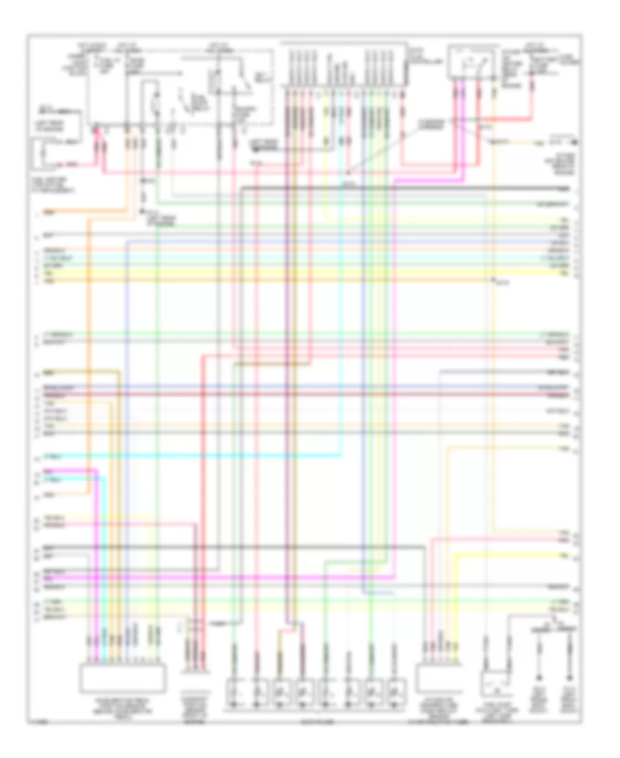
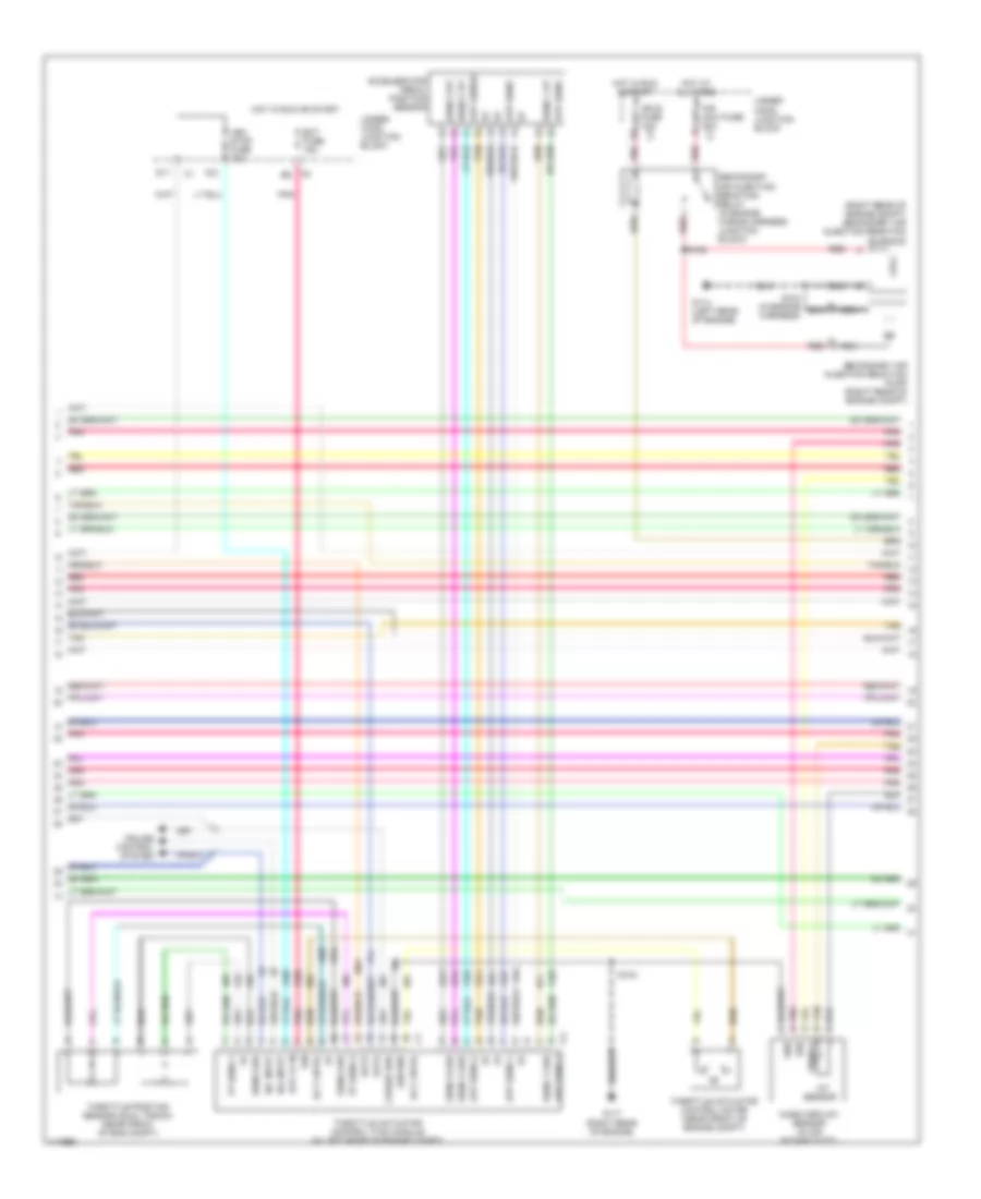
6.0L VIN U, Engine Performance Wiring Diagrams (4 of 5) for GMC Cab & Chassis Sierra 2001 3500
List of elements for 6.0L VIN U, Engine Performance Wiring Diagrams (4 of 5) for GMC Cab & Chassis Sierra 2001 3500:
- (right rear of engine compt) secondary air injection reaction solenoid
- A10
- Accelerator pedal position sensor (w/ electronic throttle control)
- Act cntrl
- Air maxi fuse 30a c7
- App sens
- App sens 1
- App sens 2
- App sens 3
- App sense
- Cruise control system
- Cruise req
- D11
- Data
- Ect fuse 15a
- Fuse block
- G114 (left rear of engine)
- G117 (right rear of engine)
- Gnd
- Ground
- Hot at all times
- Hot in run & start
- Hot in run or start
- Iat sensor
- Ign
- Ign e fuse 10a c2
- Ign0 fuse 10a
- Mass airflow sensor (in air intake duct)
- Nca
- Pnk
- Pnk d
- R/a input
- Red
- S/c input
- S103
- S104 (in engine harness)
- S108
- Secondary air injection reaction pump (right rear of engine compt)
- Secondary air injection reaction relay (in engine wiring harness junction block)
- Sens 1 grd
- Sens 1 rt
- Sens 2 grd
- Sens 2 rt
- Sens 3 grd
- Sens 3 rt
- Sens grd
- Signal
- Stp lp in
- Tan
- Tan b
- Throttle actuator control (tac) module (w/ electronic throttle control) (in left rear of engine compt)
- Throttle actuator control motor (w/ electronic throttle control) (on throttle body)
- Throttle position sensor (dual track) (w/ electronic throttle control) (on throttle body)
- Tp sens 1
- Tp sens 2
- Under- hood junction block
- Veh stop fuse 10a
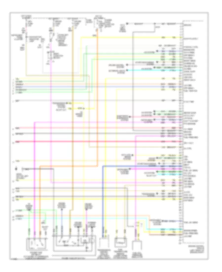
6.0L VIN U, Engine Performance Wiring Diagrams (5 of 5) for GMC Cab & Chassis Sierra 2001 3500
List of elements for 6.0L VIN U, Engine Performance Wiring Diagrams (5 of 5) for GMC Cab & Chassis Sierra 2001 3500:
- (in engine harness)
- (left front of engine) g110
- (left rear of engine) g114
- (pins 70-72 not used)
- 1-2 ss
- 2-3 ss
- 4wd low
- A/c clu
- A/c req
- A/c system
- Air pump
- Anti-lock brake system
- Anti-lock brake system (speed signal)
- Automatic trans- mission input shaft speed sensor
- Automatic transfer case control module (above c3 headlight switch)
- Cruise control system
- Cruise eng
- Ctrl
- Cyc sw in
- Delivered torq
- Egr ctrl
- Egr gnd
- Eng1 fuse 10a
- Evap canp
- Evap vent
- Front axle switch (right side of center on axle housing)
- Frt axle sw
- Fuel lev
- Fuel pmp
- Fuel sig ctrl
- Fuse block
- G117 (right rear of engine)
- Gen f
- Gen l
- Gnd
- Ho2s htr high
- Ho2s htr low
- Hot in run & start
- Hot in run & start
- Iac coil hi
- Iac coil lo
- Iat sig
- Idle air control valve (top of throttle body)
- Ign
- Ign ctrl
- Ign feed
- Ign1 fuse 10a
- Ignition coils
- Instrument cluster systems (speed signal)
- Instrument panel cluster
- Maf sig
- Malfunction indicator lamp
- Map sig
- Mil ctrl
- Nca
- Nca nca
- Pc sol hi
- Pc sol lo
- Pnk
- Pnk d
- Powertrain control module (left front of engine compt)
- Prnd c
- Recirc door
- Recirc sw
- Red
- Red c
- Ref lo
- Ref low
- Rpm out
- S103
- S151
- S152
- S153
- S154
- S156
- S157
- Sec fuel lvl
- Sec fuel pmp
- Sens gnd
- Spark plug
- Starting/charging system
- Tan
- Tft sens sig
- Tp sig
- Trans rng a
- Transfer case switch (left front of transaxle case)
- Under- hood junction block
- Vss high
- Vss low
- Vss out
- W/ atc
- W/ manual 4wd
6.6L
6.6L VIN 1, Engine Performance Wiring Diagrams, California (1 of 4) for GMC Cab & Chassis Sierra 2001 3500
List of elements for 6.6L VIN 1, Engine Performance Wiring Diagrams, California (1 of 4) for GMC Cab & Chassis Sierra 2001 3500:
- (left rear of engine)
- 12v ref
- 5v ref
- A/c system
- B/u lp supp
- Batt
- Battery
- Body control module (left side of dash)
- Can high
- Can low
- Ccp sw
- Ckp signal
- Class2 data
- Cmp sig
- Cool lev
- Coolant level switch (in coolant reservoir)
- Crankshaft position sensor (right side of harmonic balancer)
- Cruise control system
- Data link connector (under left side of dash)
- Ecm1 fuse 10a
- Ect sig
- Engine control module (left front of engine compt)
- Engine coolant temperature sensor (next to oil filler tube)
- Engine oil level switch (left rear of oil pan)
- Ficm relay
- Fuse block
- G114
- G114 (left rear of engine)
- Gen 2 to
- Ground
- Hot in run & start
- Hot w/ vehicle in reverse
- Ia htr
- Ign 0 fuse 10a
- Ign 1
- Inj1
- Inj2
- Inj3
- Inj4
- Inj5
- Inj6
- Inj7
- Inj8
- Low ref
- Nca
- Off/run/crk
- Oil lev sw
- P/n sig
- Plug sig
- Pnk
- Pto en
- Res/acc
- S102
- S103
- Set/coast
- Splice pack sp205 (behind headlamp switch)
- Starting/ charging system
- Tan
- Transmission system
- Under- hood junction block
- Veh b/u fuse 15a
- Water in fuel
- Water in fuel sensor (attached to fuel filter)
6.6L VIN 1, Engine Performance Wiring Diagrams, California (2 of 4) for GMC Cab & Chassis Sierra 2001 3500
List of elements for 6.6L VIN 1, Engine Performance Wiring Diagrams, California (2 of 4) for GMC Cab & Chassis Sierra 2001 3500:
- (in engine harness)
- (left rear of engine)
- A11
- Accelerator pedal position sensor (behind accelerator pedal)
- Battery
- Battery fuse 175a
- C11
- Camshaft position sensor (front of engine)
- Ecmb fuse 20a
- Ecmprv fuse 15a
- F1 c2
- Fuel heater (top of fuel filter element)
- Fuel ht fuse 25a
- Fuel pump (auxiliary tank) (left side frame rail)
- Fuel pump relay
- Fuse holder
- G113 (left front body mount)
- G114
- G114 (left rear of engine)
- G414 (left frame body mount)
- Glow plug controller
- Glow plugs
- Ground
- Hot at all times
- Hot in run & start
- Ign 1
- Ign 1 relay
- Intake air heater (rear of engine)
- Intake air heater relay (rear of engine)
- Intake air temperature/ mass airflow sensor (in air induction tube)
- Nca
- Plug sig
- Pnk
- Red
- Relay ctrl
- S102
- S172
- S173
- S174
- S175
- Series
- Tan
- Under- hood junction block
6.6L VIN 1, Engine Performance Wiring Diagrams, California (3 of 4) for GMC Cab & Chassis Sierra 2001 3500
List of elements for 6.6L VIN 1, Engine Performance Wiring Diagrams, California (3 of 4) for GMC Cab & Chassis Sierra 2001 3500:
- (in engine harn)
- (in injector harn)
- (in injector harn) s167
- (left rear of eng)
- (pins 49-58 not used)
- (pins 6-43 not used)
- (pins 68-81 not used)
- (pins 82-89 not used)
- (pins 95-113 not used)
- (right front of eng) g119
- Baro sensor (left side of engine)
- Boost sensor (on intake manifold)
- C12
- Can hi
- Can low
- Eng1 fuse 10a
- Engine spd
- Fuel injector control module (right front of engine, under air intake duct assembly)
- Fuel injectors
- Fuel pressure sensor
- G114
- Ground
- Hot in run & start
- Ign
- Ign 2,3,5,8
- Ign pos
- Inj 8
- Inj1
- Inj2
- Inj3
- Inj4
- Inj5
- Inj6
- Inj7
- Inj8
- Injb fuse 25a
- Nca
- Pnk
- Red
- S119
- S166
- S168
- S169
- S170
- S171
- Tan
- Transmission control system
- Under- hood junction block
6.6L VIN 1, Engine Performance Wiring Diagrams, California (4 of 4) for GMC Cab & Chassis Sierra 2001 3500
List of elements for 6.6L VIN 1, Engine Performance Wiring Diagrams, California (4 of 4) for GMC Cab & Chassis Sierra 2001 3500:
- (in engine harn)
- (left rear of eng)
- 12 v redf
- 4wd low
- 5 volt ref
- A/c clu rly
- A/c hi pres
- A/c low
- A/c req
- A/c system
- Anti-lock brake system
- App sens 1
- App sens 3
- Axle sig
- Baro sens
- Body junction block
- Boost sens
- Brake fuse 10a
- C1 c1
- Charge ind
- Chmsl supp
- Cruise control system
- Cruise fuse 10a
- Cruise on sig
- Electronic suspension system
- Engine control module (left front of engine compt)
- Engine spd
- Engine speed
- Exterior lights system
- F pmp rly ctrl
- Fog lamps fuse 15a
- Front sig hi
- Frp sens
- Fuel lev sens
- Fuel pres reg
- Fuel rail pressure regulator
- Fuel temp sig
- Fuel temperature sensor (under upper intake shield)
- Fuse block
- G114
- Gen f
- Glow plug rly
- Ground
- Hot at all times
- Hot in run
- Hot in run & start
- Ia htr
- Iat sens
- Ign 1 volt
- Ign1 fuse 10a
- Ind logic
- Instrument cluster
- Instrument cluster system
- Instrument panel cluster
- Interior lights system
- Lift/dive
- Low ref
- Maf sens
- Malfunction indicator lamp
- Mil ctrl
- Nca
- Off
- Pnk
- Power take off relay (attached to underhood fuse block bracket)
- Power take off switch
- Pto disable
- Pto engage
- Pto fdbk
- Recirc door
- Red
- Rpm out
- S103
- S163
- S164
- Set
- Sound system
- Sp203 (on top left of dash)
- Starting/charging system
- Stoplight switch (top of brake pedal bracket)
- Tan
- Tcc brake
- Tcm mil
- Transmission control module (left front of eng compt)
- Transmission control system
- Transmission system
- Under- hood junction block
- Vss
- Vss high
- Wait to start
6.6L VIN 1, Engine Performance Wiring Diagrams, Except California (1 of 4) for GMC Cab & Chassis Sierra 2001 3500
List of elements for 6.6L VIN 1, Engine Performance Wiring Diagrams, Except California (1 of 4) for GMC Cab & Chassis Sierra 2001 3500:
- (left rear of engine)
- 12v ref
- 5v ref
- A/c system
- B/u lp supp
- Batt
- Battery
- Body control module (left side of dash)
- Can high
- Can low
- Ccp sw
- Ckp signal
- Class2 data
- Cmp sig
- Cool lev
- Coolant level switch (in coolant reservoir)
- Crankshaft position sensor (right side of harmonic balancer)
- Cruise control system
- Data link connector (under left side of dash)
- Ecm1 fuse 10a
- Ect sig
- Engine control module (left front of engine compt)
- Engine coolant temperature sensor (next to oil filler tube)
- Engine oil level switch (left rear of oil pan)
- Ficm relay
- Fuse block
- G114
- G114 (left rear of engine)
- Gen 2 to
- Ground
- Hot in run & start
- Hot w/ vehicle in reverse
- Ia htr
- Ign 0 fuse 10a
- Ign 1
- Inj1
- Inj2
- Inj3
- Inj4
- Inj5
- Inj6
- Inj7
- Inj8
- Low ref
- Nca
- Off/run/crk
- Oil lev sw
- P/n sig
- Plug sig
- Pnk
- Pto en
- Res/acc
- S102
- S103
- Set/coast
- Splice pack sp205 (behind headlamp switch)
- Starting/ charging system
- Tan
- Transmission system
- Under- hood junction block
- Veh b/u fuse 15a
- Water in fuel
- Water in fuel sensor (attached to fuel filter)
6.6L VIN 1, Engine Performance Wiring Diagrams, Except California (2 of 4) for GMC Cab & Chassis Sierra 2001 3500
List of elements for 6.6L VIN 1, Engine Performance Wiring Diagrams, Except California (2 of 4) for GMC Cab & Chassis Sierra 2001 3500:
- (left rear of engine)
- A11
- Accelerator pedal position sensor (behind accelerator pedal)
- Battery fuse 175a
- C11
- Camshaft position sensor (front of engine)
- Ecmb fuse 20a
- Ecmprv fuse 15a
- F1 c2
- Fuel heater (top of fuel filter element)
- Fuel ht fuse 25a
- Fuel pump (auxiliary tank) (left side frame rail)
- Fuel pump relay
- Fuse holder
- G113 (left front body mount)
- G114
- G114 (left rear of engine)
- G414 (left frame body mount)
- Glow plug relay
- Glow plug/ intake heater relay assembly
- Glow plugs
- Hot at all times
- Hot in run & start
- Ign 1 relay
- Intake air heater (rear of engine)
- Intake air heater relay
- Intake air temperature/ mass airflow sensor (in air induction tube)
- Nca
- Pnk
- Red
- S102
- Series
- Tan
- Under- hood junction block
6.6L VIN 1, Engine Performance Wiring Diagrams, Except California (3 of 4) for GMC Cab & Chassis Sierra 2001 3500
List of elements for 6.6L VIN 1, Engine Performance Wiring Diagrams, Except California (3 of 4) for GMC Cab & Chassis Sierra 2001 3500:
- (in engine harn)
- (in injector harn)
- (in injector harn) s167
- (left rear of eng)
- (pins 49-58 not used)
- (pins 6-43 not used)
- (pins 68-81 not used)
- (pins 82-89 not used)
- (pins 95-113 not used)
- (right front of eng) g119
- Baro sensor (left side of engine)
- Boost sensor (on intake manifold)
- C12
- Can hi
- Can low
- Eng1 fuse 10a
- Engine spd
- Fuel injector control module (right front of engine, under air intake duct assembly)
- Fuel injectors
- Fuel pressure sensor
- G114
- Ground
- Hot in run & start
- Ign
- Ign 2,3,5,8
- Ign pos
- Inj 8
- Inj1
- Inj2
- Inj3
- Inj4
- Inj5
- Inj6
- Inj7
- Inj8
- Injb fuse 25a
- Nca
- Pnk
- Red
- S119
- S166
- S168
- S169
- S170
- S171
- Tan
- Transmission control system
- Under- hood junction block
6.6L VIN 1, Engine Performance Wiring Diagrams, Except California (4 of 4) for GMC Cab & Chassis Sierra 2001 3500
List of elements for 6.6L VIN 1, Engine Performance Wiring Diagrams, Except California (4 of 4) for GMC Cab & Chassis Sierra 2001 3500:
- (in engine harn)
- (left rear of eng)
- 12 v redf
- 4wd low
- 5 volt ref
- A/c clu rly
- A/c hi pres
- A/c low
- A/c req
- A/c system
- Anti-lock brake system
- App sens 1
- App sens 3
- Axle sig
- Baro sens
- Body junction block
- Boost sens
- Brake fuse 10a
- C1 c1
- Charge ind
- Chmsl supp
- Cruise control system
- Cruise fuse 10a
- Cruise on sig
- Electronic suspension system
- Engine control module (left front of engine compt)
- Engine spd
- Engine speed
- Exterior lights system
- F pmp rly ctrl
- Fog lamps fuse 15a
- Front sig hi
- Frp sens
- Fuel lev sens
- Fuel pres reg
- Fuel rail pressure regulator
- Fuel temp sig
- Fuel temperature sensor (under upper intake shield)
- Fuse block
- G114
- Gen f
- Glow plug rly
- Ground
- Hot at all times
- Hot in run
- Hot in run & start
- Ia htr
- Iat sens
- Ign 1 volt
- Ign1 fuse 10a
- Ind logic
- Instrument cluster
- Instrument cluster system
- Instrument panel cluster
- Interior lights system
- Lift/dive
- Low ref
- Maf sens
- Malfunction indicator lamp
- Mil ctrl
- Nca
- Off
- Pnk
- Power take off relay (attached to underhood fuse block bracket)
- Power take off switch
- Pto disable
- Pto engage
- Pto fdbk
- Recirc door
- Red
- Rpm out
- S103
- S163
- S164
- Set
- Sound system
- Sp203 (on top left of dash)
- Starting/charging system
- Stoplight switch (top of brake pedal bracket)
- Tan
- Tcc brake
- Tcm mil
- Transmission control module (left front of eng compt)
- Transmission control system
- Transmission system
- Under- hood junction block
- Vss
- Vss high
- Wait to start
8.1L
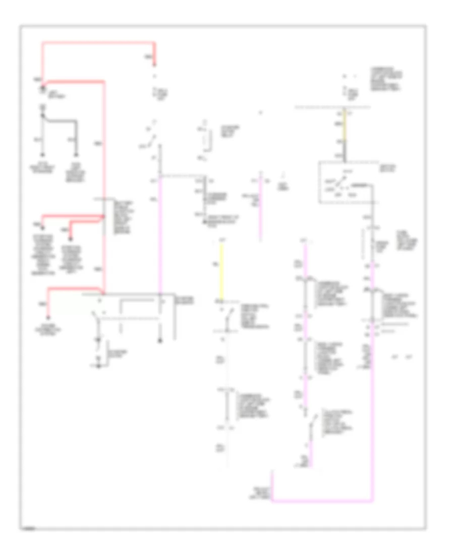
8.1L VIN G, Engine Performance Wiring Diagrams (1 of 5) for GMC Cab & Chassis Sierra 2001 3500
List of elements for 8.1L VIN G, Engine Performance Wiring Diagrams (1 of 5) for GMC Cab & Chassis Sierra 2001 3500:
- (below steering column) data link connector
- (lower right rear of engine) crankshaft position sensor
- +5v
- Body control module (below steering column)
- Brk sw
- C10
- C11
- C12
- Ckp
- Cls 2 data
- Clutch sw
- Cmp
- Coolant lev
- E12
- Ecm1 fuse 10a
- Ecmb fuse 20a
- Ect sig
- Egr input
- Electronic suspension system
- Fuse block
- G117 (right rear of engine)
- Gnd
- Ho2s hi
- Ho2s lo
- Hot at all times
- Hot in run & start
- Ign
- Ign 0 fuse 10a
- Inj1
- Inj2
- Inj3
- Inj4
- Inj5
- Inj6
- Inj7
- Inj8
- Inja fuse 15a
- Injb fuse 15a
- Injectors
- Ks signal
- Lift/dive sig
- Low ref
- Nca
- O2b fuse 15a
- Oil lev
- Pnk
- Powertrain control module (left front of engine compt)
- Prnd p
- Pto enable
- Pto eng kill
- Pto engage
- Pto status
- Ref low
- Req torque
- S103
- S152
- S154
- Sens gnd
- Sens rtn
- Serial data
- Sp205 (behind headlamp switch)
- Tan
- Transmission control system
- Under- hood junction block
8.1L VIN G, Engine Performance Wiring Diagrams (2 of 5) for GMC Cab & Chassis Sierra 2001 3500
List of elements for 8.1L VIN G, Engine Performance Wiring Diagrams (2 of 5) for GMC Cab & Chassis Sierra 2001 3500:
- (in engine harness)
- (left front of engine)
- (left rear of engine)
- (left rear of engine) g114
- Ecm b fuse 20a
- Engine coolant level switch (in coolant reservoir)
- Engine coolant temperature sensor (left front of cylinder head)
- Engine oil level switch (right side of oil pan)
- Fuel pump relay
- G104
- G110
- G117 (right rear of engine)
- G402 (left frame body mount bracket)
- Heated oxygen sensor (bank 1 sensor 1) (left exh pipe before converter)
- Heated oxygen sensor (bank 1 sensor 2) (left exh pipe after converter)
- Heated oxygen sensor (bank 2 sensor 1) (right exh pipe before converter)
- Heated oxygen sensor (bank 2 sensor 2) (right exh pipe after converter)
- Hot at all times
- Knock sensor 1 (under intake manifold)
- Knock sensor 2 (under intake manifold)
- Nca
- Park/neutral position switch (left side of transmission)
- Pnk
- Primary fuel pump/ level sensor (in fuel tank)
- S103
- S104
- S114a
- S115
- S116
- S312
- Secondary fuel pump relay
- Secondary fuel pump/ level sensor (in fuel tank)
- Tan
- Under- hood junction block
8.1L VIN G, Engine Performance Wiring Diagrams (3 of 5) for GMC Cab & Chassis Sierra 2001 3500
List of elements for 8.1L VIN G, Engine Performance Wiring Diagrams (3 of 5) for GMC Cab & Chassis Sierra 2001 3500:
- Body junction block
- Brake fuse 10a
- Camshaft position sensor (on left side of timing cover)
- Clutch pedal position switch (top of pedal bracket)
- Cruise control system
- Cruise fuse 10a
- Del torque
- Evap canister purge valve (top right rear of engine)
- Evap canister vent valve (left front side of fuel tank)
- Exhaust gas recirculation valve (top right front of engine)
- F12
- Fog lamps fuse 15a
- Fuel tank pressure sensor (in fuel tank)
- Fuse block
- G202 (upper left side of dash)
- Harn)
- Hot in run
- Hot in run & start
- Ind logic
- Interior lights system
- Manifold absolute pressure sensor (top rear of engine)
- Mil req
- Off
- Pnk
- Pnk a
- Pnk b
- Power take off relay (on underhood junction block)
- Power take off switch
- Red
- Red e
- Req torque
- S161
- S162
- S163
- S164 (engine harn)
- Set
- Stop lps fuse 20a
- Stop- lamp switch (top of brake pedal bracket)
- Tan
- Transmission control module (left front of engine compt)
- Under- hood junction block
- Unm tor
- Vehicle speed sensor (left rear of transmission)
- Vss
- Vss adapter (4wd) (left side of trans)
8.1L VIN G, Engine Performance Wiring Diagrams (4 of 5) for GMC Cab & Chassis Sierra 2001 3500
List of elements for 8.1L VIN G, Engine Performance Wiring Diagrams (4 of 5) for GMC Cab & Chassis Sierra 2001 3500:
- (right rear of engine compt) secondary air injection reaction solenoid
- A10
- Accelerator pedal position sensor
- Act cntrl
- Air maxi fuse 30a c7
- App sens
- App sens 1
- App sens 2
- App sens 3
- App sense
- Cruise control system
- Cruise req
- D11
- Data
- Ect fuse 15a
- G114 (left rear of engine)
- G117 (right rear of engine)
- Gnd
- Ground
- Hot at all times
- Hot in run & start
- Hot in run or start
- Iat sensor
- Ign
- Ign e fuse 10a c2
- Mass airflow sensor (in air intake duct)
- Nca
- Pnk
- Pnk d
- R/a input
- Red
- S/c input
- S103
- S104 (in engine harness)
- S108
- Secondary air injection reaction pump (right rear of engine compt)
- Secondary air injection reaction relay (in engine wiring harness junction block)
- Sens 1 grd
- Sens 1 rt
- Sens 2 grd
- Sens 2 rt
- Sens 3 grd
- Sens 3 rt
- Sens grd
- Signal
- Stp lp in
- Tan
- Tan b
- Throttle actuator control (tac) module (in left rear of engine compt)
- Throttle actuator control motor (near front of engine compt)
- Throttle position sensor (dual track) (near front of eng compt)
- Tp sens 1
- Tp sens 2
- Under- hood junction block
- Veh stop fuse 10a
8.1L VIN G, Engine Performance Wiring Diagrams (5 of 5) for GMC Cab & Chassis Sierra 2001 3500
List of elements for 8.1L VIN G, Engine Performance Wiring Diagrams (5 of 5) for GMC Cab & Chassis Sierra 2001 3500:
- (in engine harness)
- (left front of engine) g110
- (left rear of engine) g114
- (pins 70-71 not used)
- (pins 76-79 not used)
- 4wd low
- A/c clu
- A/c req
- A/c system
- Air pump
- Anti-lock brake system (speed signal)
- Automatic trans- mission input shaft speed sensor
- Automatic transfer case control module (above c3 headlight switch)
- Cruise control system
- Cruise eng
- Ctrl
- Cyc sw in
- Delivered torq
- Egr ctrl
- Egr gnd
- Eng1 fuse 10a
- Evap canp
- Evap vent
- Front axle switch (right side of center on axle housing)
- Frt axle sw
- Fuel lev
- Fuel pmp
- Fuel sig ctrl
- Fuse block
- G117 (right rear of engine)
- Gen f
- Gen l
- Gnd
- Ho2s htr hi
- Ho2s htr high
- Ho2s htr low
- Ho2s low ctrl
- Hot in run & start
- Hot in run & start
- Iat sig
- Ign
- Ign ctrl
- Ign feed
- Ign1 fuse 10a
- Ignition coils
- Instrument cluster systems (speed signal)
- Instrument panel cluster
- Maf sig
- Malfunction indicator lamp
- Map sig
- Mil ctrl
- Nca
- Nca nca
- Pnk
- Pnk d
- Powertrain control module (left front of engine compt)
- Recirc door
- Recirc sw
- Red
- Red c
- Ref lo
- Ref low
- Rpm out
- S103
- S148
- S149
- S151
- S153
- S159
- S160
- Sec fuel lvl
- Sec fuel pmp
- Sens gnd
- Spark plug
- Starting/charging system
- Tan
- Tcc ctrl
- Trans mil
- Transfer case switch (left front of transaxle case)
- Under- hood junction block
- Vss high
- Vss low
- Vss out
- W/ atc
- W/ manual 4wd
EXTERIOR LIGHTS
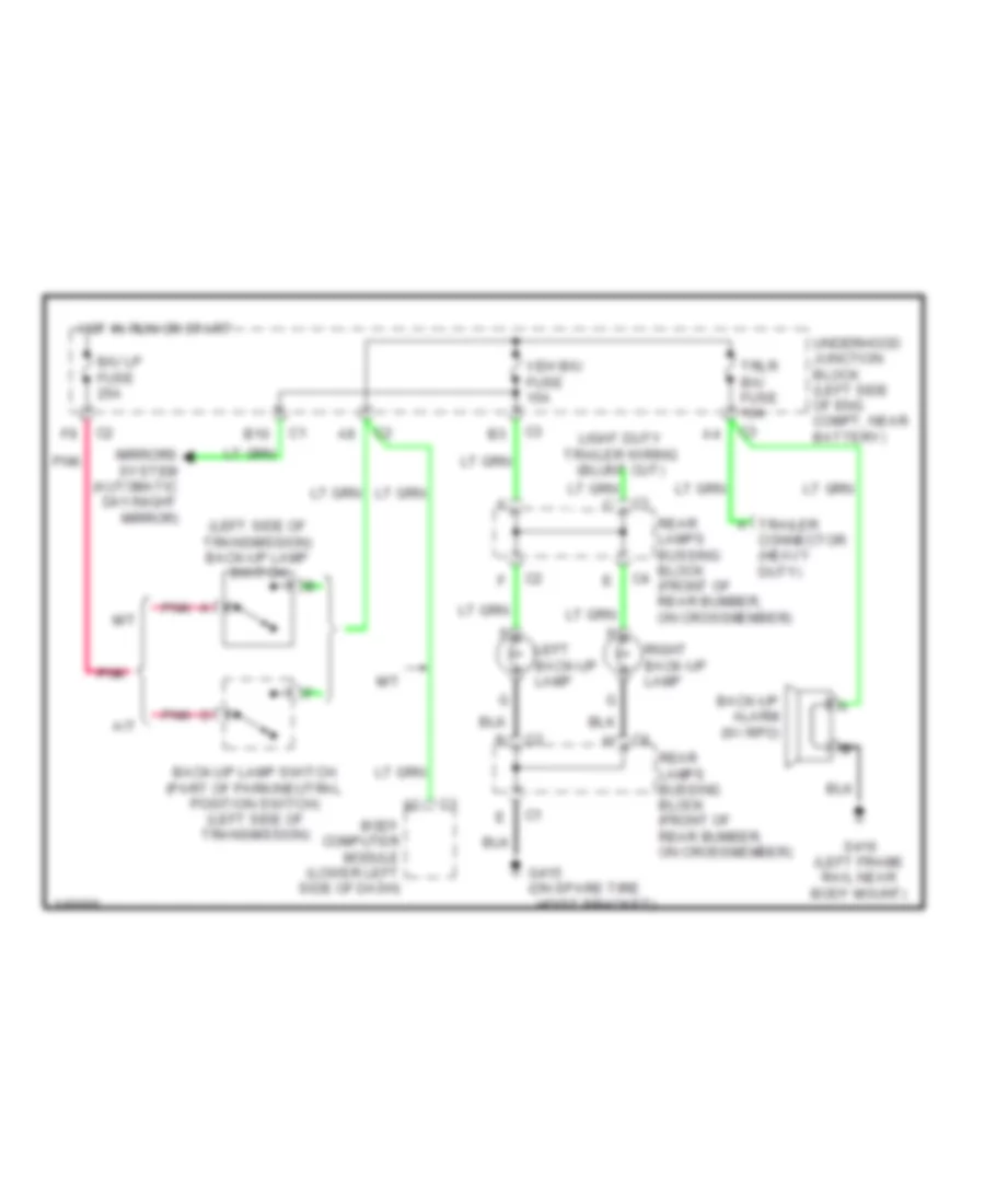
Back-up Lamps Wiring Diagram for GMC Cab & Chassis Sierra 2001 3500
List of elements for Back-up Lamps Wiring Diagram for GMC Cab & Chassis Sierra 2001 3500:
- (left side of transmission) back-up lamp switch
- A trailer connector (heavy duty)
- A/t
- B/u lp fuse 25a
- B10
- Back-up alarm (w/ rpo)
- Back-up lamp switch (part of park/neutral position switch) (left side of transmission)
- Body computer module (lower left side of dash)
- G415 (on spare tire
- Hoist bracket)
- Hot in run or start
- Left back-up lamp
- M/t
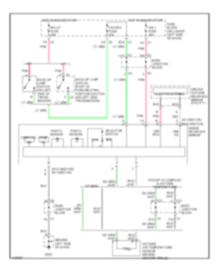
- Mirrors system (automatic day/night mirror)
- Pnk
- Rear lamps bussing block (front of rear bumber, on crossmember)
- Right back-up lamp
- S416 (left frame rail near body mount)
- Trlr b/u fuse 10a
- Underhood junction block (left side of eng compt, near battery)
- Veh b/u fuse 15a
Exterior Lamps Wiring Diagram for GMC Cab & Chassis Sierra 2001 3500
List of elements for Exterior Lamps Wiring Diagram for GMC Cab & Chassis Sierra 2001 3500:
- (at roof marker lamps) s200
- (left side of dash) body junction block
- (left side of dash) fuse block
- (left side of eng comt, near battery) underhood junction block
- (upper right kick panel)
- A c3
- A10
- A12
- A4 c1
- Auto
- B10
- Base
- Body control module (lower left side of dash)
- Body junction block (left side of dash)
- Bulbs
- C1 b11
- C1 b12
- C1 b2
- C1 b7
- C1 d
- C1 f6
- C1 f7
- C11 c1
- C2 a
- C2 a6
- C2 a7
- C2 b6
- C2 c
- C2 d
- C2 d11
- C2 d12
- C3 e2
- C3 h
- C4 a
- C4 c
- C4 d
- C4 f
- C6 b
- C6 g
- Center high mount stop lamp/ cargo lamp
- Chmsl fuse 10a
- Clear- ance lamps
- Cruise control system
- D10
- D11
- E c1
- F nca
- F11
- F12
- Fr prk fuse 10a
- Fuse block (lower left side of dash)
- Fuse block (under left side of dash)
- G108 (left radiator support bracket)
- G200 (upper left kick panel)
- G203
- G203 (upper right kick panel)
- G300 (under driver seat)
- G415 (on spare tire hoist bracket)
- Haz lp fuse 20a
- Hazard
- Head
- Headlamp & panel dimmer switch
- Hot at all times
- Hot in run or start
- I/p junction block (lower right side of dash)
- Instrument cluster
- Int prk fuse 10a
- Interior lights system
- Left
- Left front marker lamp
- Left front park/ turn lamp
- Left license lamp
- Left outside power mirror
- Left rear turn lamp
- Left tail/ stop- lamp
- Left turn in
- Left turn ind
- Lr prk fuse 10a
- Lt turn fuse 10a
- Nca
- Nca h
- Normal
- Park
- Park lamp relay
- Park lps fuse 30a
- Park rly ctrl
- Pnk
- Puddle lamp relay
- Puddle rly ctrl
- Rear lamps junction block (front of rear bumper, on cross- member)
- Right
- Right front marker lamp
- Right front park/ turn lamp
- Right license lamp
- Right outside power mirror
- Right rear turn lamp
- Right tail/ stop- lamp
- Right turn in
- Right turn ind
- Roof beacon provision
- Roof beacon relay (left "b" pillar)
- Roof beacon switch
- Roof marker lamps
- Rr prk fuse 10a
- Rt turn fuse 10a
- S100
- S101
- S201
- Seo 1 fuse 15a
- Seo 2 fuse 30a
- Sp203
- Stop lamp switch (on brake pedal support bracket)
- Stop lps fuse 20a
- Throttle actuator control module
- Trailer circuit
- Trailer wiring provision
- Turn fuse 20a
- Turn/ hazard switch
- Turn/hazard flasher
- Underhood junction block (left side of eng compt, near battery)
- Uplevel
- Veh stop fuse 10a
Trailer/Camper Adapter Wiring Diagram for GMC Cab & Chassis Sierra 2001 3500
List of elements for Trailer/Camper Adapter Wiring Diagram for GMC Cab & Chassis Sierra 2001 3500:
- (in camper wiring harn)
- Body control module
- Body junction block (left side of dash)
- C1 c
- C1 c11
- C1 f2
- C10 c1
- C2 d10
- C3 b3
- C3 e1
- C3 e5
- C5 a
- C5 b
- C5 c
- C5 d
- C5 f
- Camper extension
- Camper in-line connector
- Camper wiring (pickup only)
- Chmsl fuse 10a
- D10
- E10
- F c1
- F10 c2
- G203 (upper left kick panel)
- G415 (on spare tire hoist bracket)
- Heavy duty trailer wiring
- Hot at all times
- Hot with back-up lamp switch closed
- Hot with park lamp relay energized
- Hot with stop lamp switch depressed
- Int prk fuse 10a
- Light duty trailer wiring
- Nca
- Pickup only
- Red
- S400 (in camper wiring harn)
- S401 (in camper wiring harn)
- S402 (in camper wiring harn)
- S403 (in camper wiring harn)
- S404 (in camper wiring harn)
- S405
- S406
- Splice pack
- Stud 1
- Stud 1 maxi fuse 40a
- Stud 2
- Stud 2 maxi fuse 30a
- Trailer connector
- Trailer in-line connector
- Trl l trn fuse 10a
- Trl prk fuse 15a
- Trl r trn fuse 10a
- Trlr b/u fuse 15a
- Turn/ hazard switch
- Underhood junction block (left side of eng compt, near battery)
- Utilities only
- Veh b/u fuse 15a
GROUND DISTRIBUTION
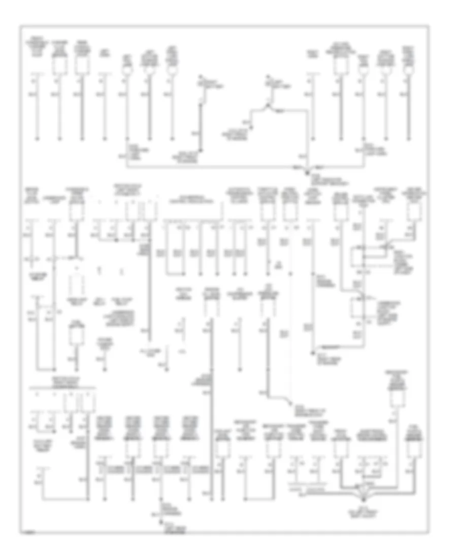
Ground Distribution Wiring Diagram (1 of 4) for GMC Cab & Chassis Sierra 2001 3500
List of elements for Ground Distribution Wiring Diagram (1 of 4) for GMC Cab & Chassis Sierra 2001 3500:
- (4.3l) g119 (right front of engine)
- (6.6l) g119 (right front of engine)
- (others) (canada)
- 4.3l
- A c1
- A/c
- A/c high pressure recirculating switch
- A/c low pressure switch
- All other gas
- Automatic transmission control (allison)
- Auxiliary
- B8 c2
- Battery relay
- Body junction block (under left side of dash)
- Brake fluid
- C d
- C2 a7
- Coil module
- Compressor clutch
- Coolant level switch
- Cruise control module
- D12
- Data link connector (dlc)
- Driver information center (dic)
- Electronic brake control module (ebcm)
- Engine
- Front axle actuator
- Front windshield washer fluid pump
- Fuel heater
- Fuel pump & sender assembly
- Fuel pump relay
- G108 (left radiator support bracket)
- G113 (on left front body mount)
- G114 (left rear of engine)
- G117 (right rear of engine)
- G132 (right front of engine block)
- Headlamp relay
- Heated oxygen sensor (ho2s) (bank 1 sensor 1)
- Heated oxygen sensor (ho2s) (bank 1 sensor 2)
- Heated oxygen sensor (ho2s) (bank 2 sensor 1)
- Heated oxygen sensor (ho2s) (bank 2 sensor 2)
- Ign 1 relay
- Ignition
- Ignition coils (left bank) (v8 gas only)
- Ignition coils (right bank) (v8 gas only)
- Instrument panel cluster (ipc)
- Left battery
- Left daytime running lamp (drl)
- Left fog lamp
- Left horn
- Left park/ turn signal lamp
- Level switch
- Mass air flow (maf) sensor
- Motor module
- Nca
- Oil level switch
- Park/ neutral position switch
- Power
- Powertrain control module (pcm)
- Rear window washer pump
- Right battery
- Right daytime running lamp (drl)
- Right fog lamp
- Right horn
- Right park/ turn signal lamp
- S102 (engine harness)
- S103 (engine harness)
- S156 (eng harn)
- S157 (engine harn)
- Secondary air injection (air) pump
- Secondary air injection (air) solenoid
- Secondary fuel pump & sender assembly
- Starter relay
- Takeoff (pto)
- Throttle actuator control module
- Transfer case control module
- Transfer case shift control switch
- Underhood junction block (left side of engine compt)
- Underhood lamp
- V8 gas
- W/atc
- W/o atc
- Washer fluid level sensor
- Windshield wiper
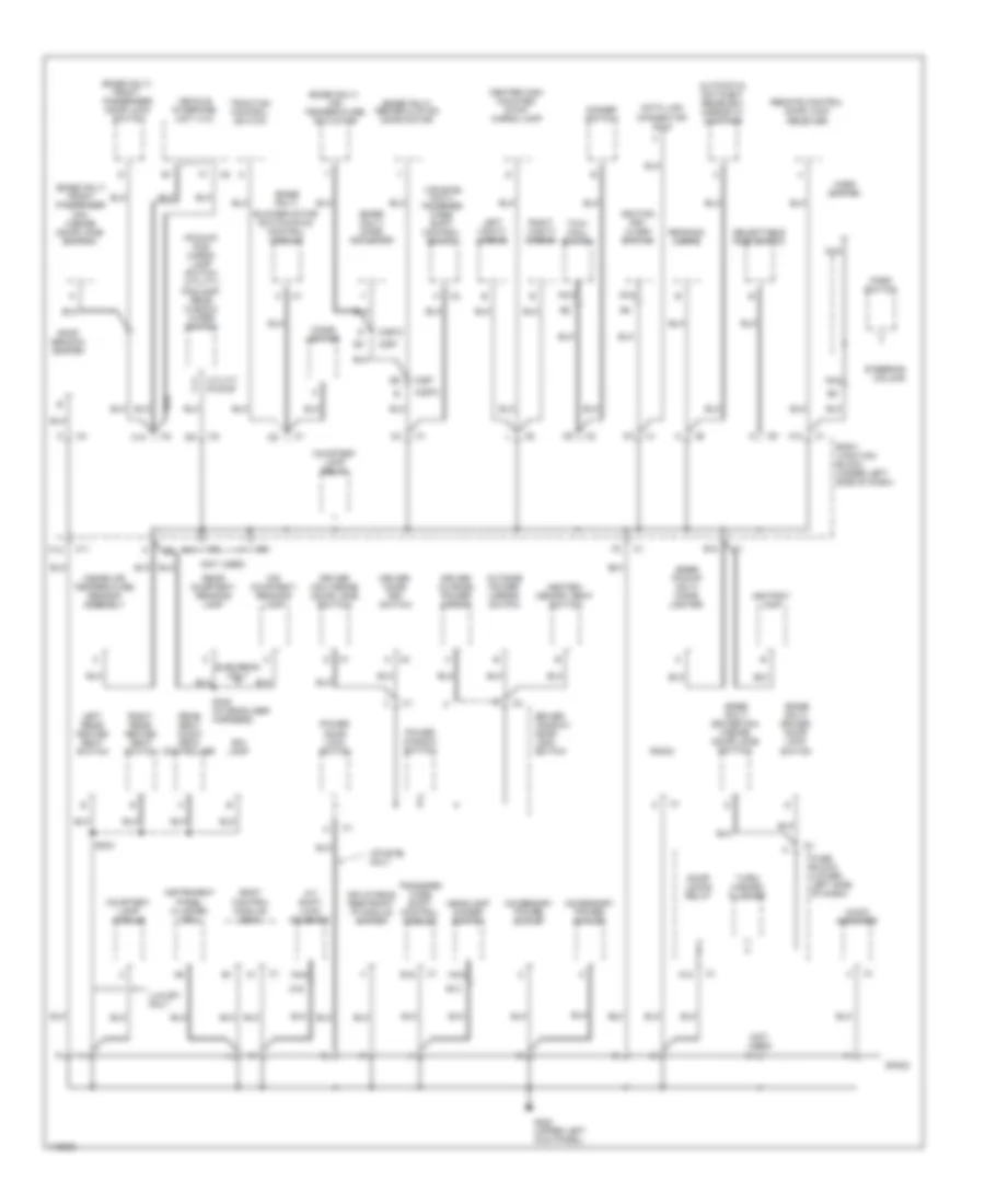
Ground Distribution Wiring Diagram (2 of 4) for GMC Cab & Chassis Sierra 2001 3500
List of elements for Ground Distribution Wiring Diagram (2 of 4) for GMC Cab & Chassis Sierra 2001 3500:
- (base only)
- (base only) air temperature actuator
- (base only) driver door lock switch
- (base only) driver mini wedge (door jamb switch)
- (base only) front passenger door lock switch
- (base only) front passenger mini wedge (door jamb switch)
- (base only) mode actuator
- (base only) recirculation door motor
- (base pickup only) cigar lighter
- (not used)
- (pickup) fog/ cargo lamp switch (utility) foglamp/ rear window wiper switch
- (uplevel only) transfer case shift control switch
- A utility pickup
- A/t shift lock solenoid
- A12
- A16
- Accessory power outlet
- Ashtray lamp
- Audio amplifier
- Automatic day-night rearview mirror w/ compass
- B12
- Bin lamp
- Blower motor switch/hvac control module
- Body control module (bcm)
- Body junction block (under left side of dash)
- C10
- C11
- C297
- C297c
- Center high mounted stop/ cargo lamp
- Cigar lighter
- Courtesy lamp module
- Courtesy lamp relay
- Data link connector (dlc)
- Dimmer switch
- Door locks relay
- Driver door key switch
- Driver mini wedge (door jamb switch)
- Driver outside power mirror
- Driver window/ door lock switch
- E13
- E16
- F12
- Fuse block (lower left side of dash)
- G200 (upper left kick panel)
- Headlamp dimmer switch
- Heated/ memory seat switch
- Horn switch
- Ignition key alarm switch
- Inflatable restraint ip module switch
- Inside air temperature sensor assembly
- Instrument panel cluster (ipc)
- Left rear heated seat switch
- Left vanity mirror
- Luxury only
- Mid courtesy/ reading lamp
- Nca
- Outside power mirror switch
- Park switch
- Power door lock switch
- Power window switch
- Radio
- Reading lamps
- Rear courtesy/ reading lamp
- Rear seat audio (rsa) controller
- Remote control door lock receiver
- Right rear heated seat switch
- Right vanity mirror
- Roof beacon switch
- S303
- S305 (in headliner harness)
- Selectable ride switch
- Sp203
- Steering column
- Suburban only
- Tow/ haul switch
- Traction control switch
- Transfer case shift control module
- Turn/ hazard flasher
- Uplevel only
- Vehicle interface unit (viu)
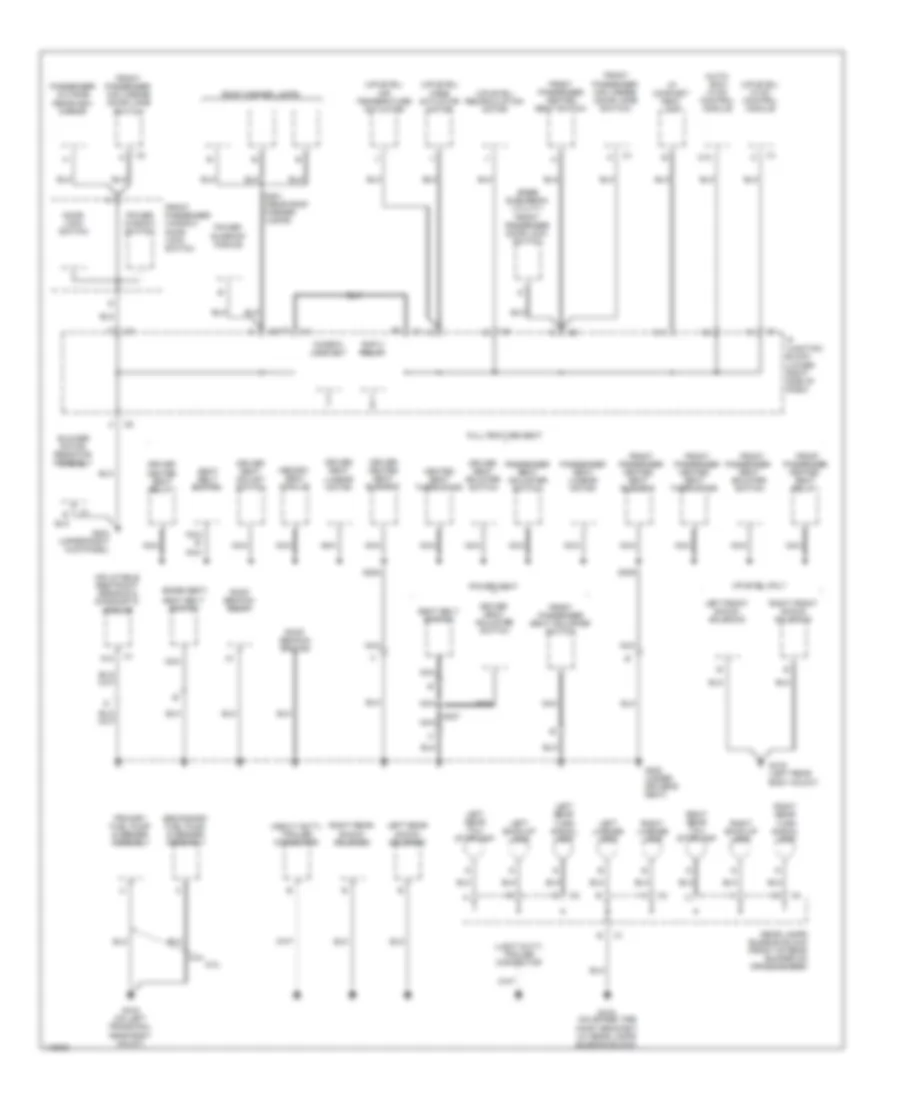
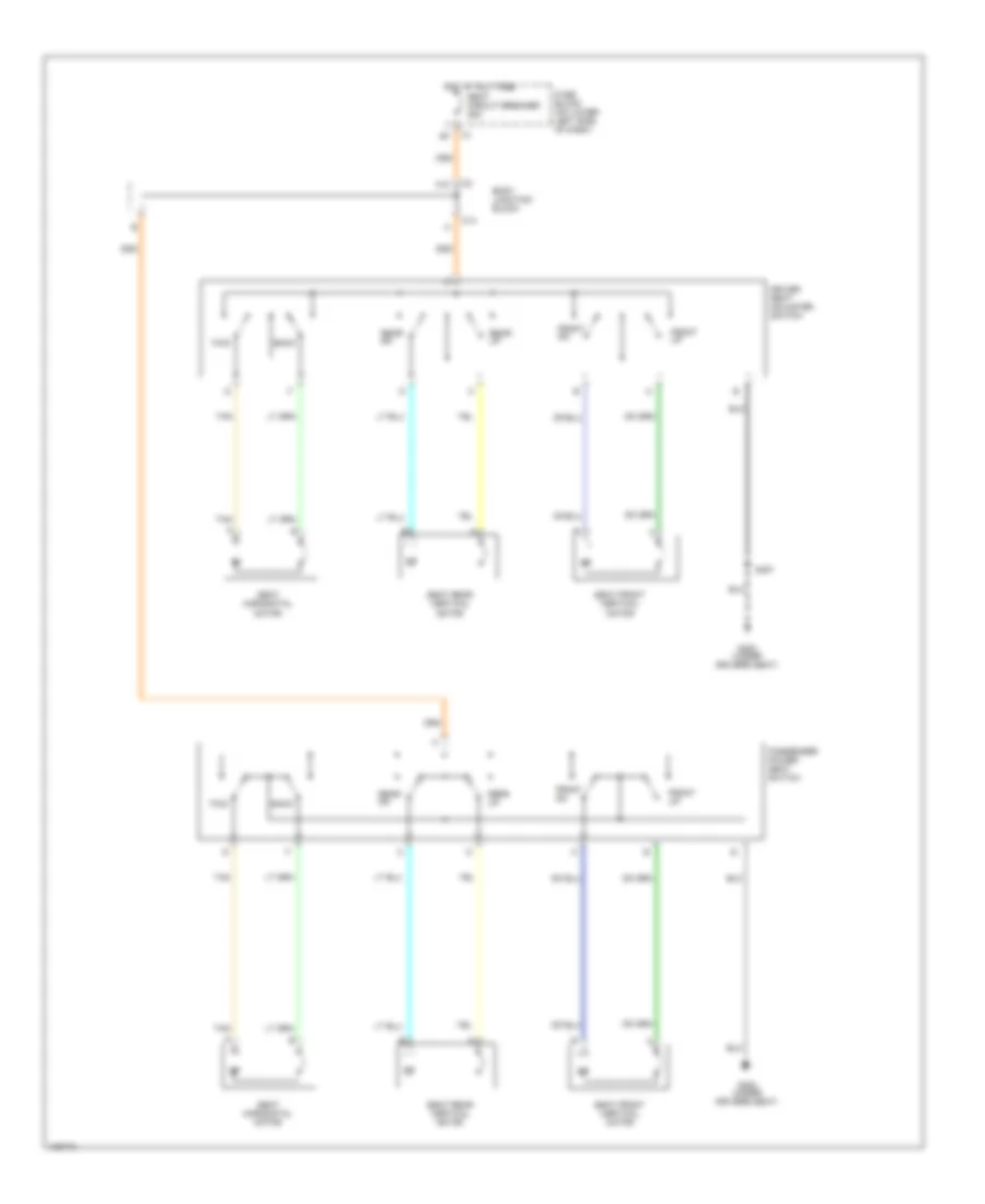
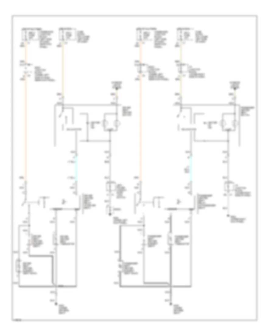
Ground Distribution Wiring Diagram (3 of 4) for GMC Cab & Chassis Sierra 2001 3500
List of elements for Ground Distribution Wiring Diagram (3 of 4) for GMC Cab & Chassis Sierra 2001 3500:
- (auto- ecc) hvac control module
- (base seat)
- (base suburban/ utility) front passenger door lock switch
- (heavy duty) trailer connector
- (light duty) trailer connector
- (uplevel) air temperature actuator
- (uplevel) hvac control module
- (uplevel) mode actuator motor
- (uplevel) recirculation motor
- 6.0l
- A11
- A18
- Blower motor resistor assembly
- C10
- Door lock switch
- Driver heated seat element
- Driver heated seat relay
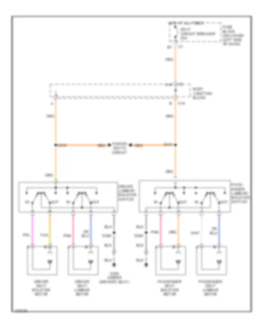
- Driver seat adjust switch
- Driver seat adjuster switch
- Driver seat bolster switch
- Driver seat lumbar motor
- Front
- Front passenger heated seat element
- Front passenger heated seat relay
- Front passenger heated seat switch
- Front passenger heated seat thermistor
- Front passenger mini wedge (door jamb switch
- Front passenger mini wedge (door jamb switch)
- Front passenger seat adjuster switch
- Front passenger window/ door lock switch
- Full feature seat
- G203 (upper right kick panel)
- G300 (under driver's seat)
- G415 (on spare tire hoist bracket) (w/ rear lamps bussing block)
- G416 (left rear body mount)
- G416 (on left frame rail near body mount)
- Heated seat thermistor
- I/p compart- ment lamp
- Inflatable restraint sensing & diagnostic module
- Ip junction block (lower right side of dash)
- Left back-up lamp
- Left front shock solenoid
- Left license lamp
- Left rear shock solenoid
- Left rear tail/ stoplamp
- Left rear turn signal lamp
- Memory seat module
- Nca
- Nca b
- Passenger outside rearview mirror
- Passenger seat adjuster switch
- Passenger seat bolster switch
- Passenger seat lumbar motor
- Power seat
- Power sunroof module
- Power window switch
- Primary fuel pump & sender assembly
- Rap 2 relay
- Rear lamps bussing block (front of rear bumper on crossmember)
- Right back-up lamp
- Right front shock solenoid
- Right license lamp
- Right rear shock solenoid
- Right rear tail/ stoplamp
- Right rear turn signal lamp
- Roof beacon ground
- Roof beacon relay
- Roof marker lamps
- S201 (near roof marker lamps)
- S307
- S308
- S309
- Seat belt switch
- Secondary fuel pump & sender assembly
- Uplevel only
- Window lock out
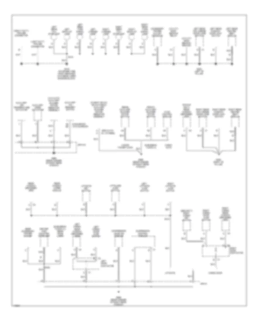
Ground Distribution Wiring Diagram (4 of 4) for GMC Cab & Chassis Sierra 2001 3500
List of elements for Ground Distribution Wiring Diagram (4 of 4) for GMC Cab & Chassis Sierra 2001 3500:
- (ecc-auto) c2
- (front) auxiliary blower motor switch
- (heavy duty) trailer connector
- (light duty) trailer connector
- (others)
- (pickup only) rear window defogger grid
- (rear) auxiliary blower motor switch
- (security) right cargo key switch
- (suburban/ yukon xl) rear dome lamp
- (utility) roof beacon ground
- (utility) roof beacon relay
- (w/heat or a/c, or auto-ecc) auxiliary blower motor resistor assembly
- (w/o auto) auxiliary blower motor resistor assembly
- (w/o sunroof)
- (w/sunroof)
- 4 door tahoe/yukon
- A a
- A8 b8
- Accessory power outlet (console)
- Auxiliary a/c request switch
- Auxiliary air temperature actuator
- Auxiliary mode actuator
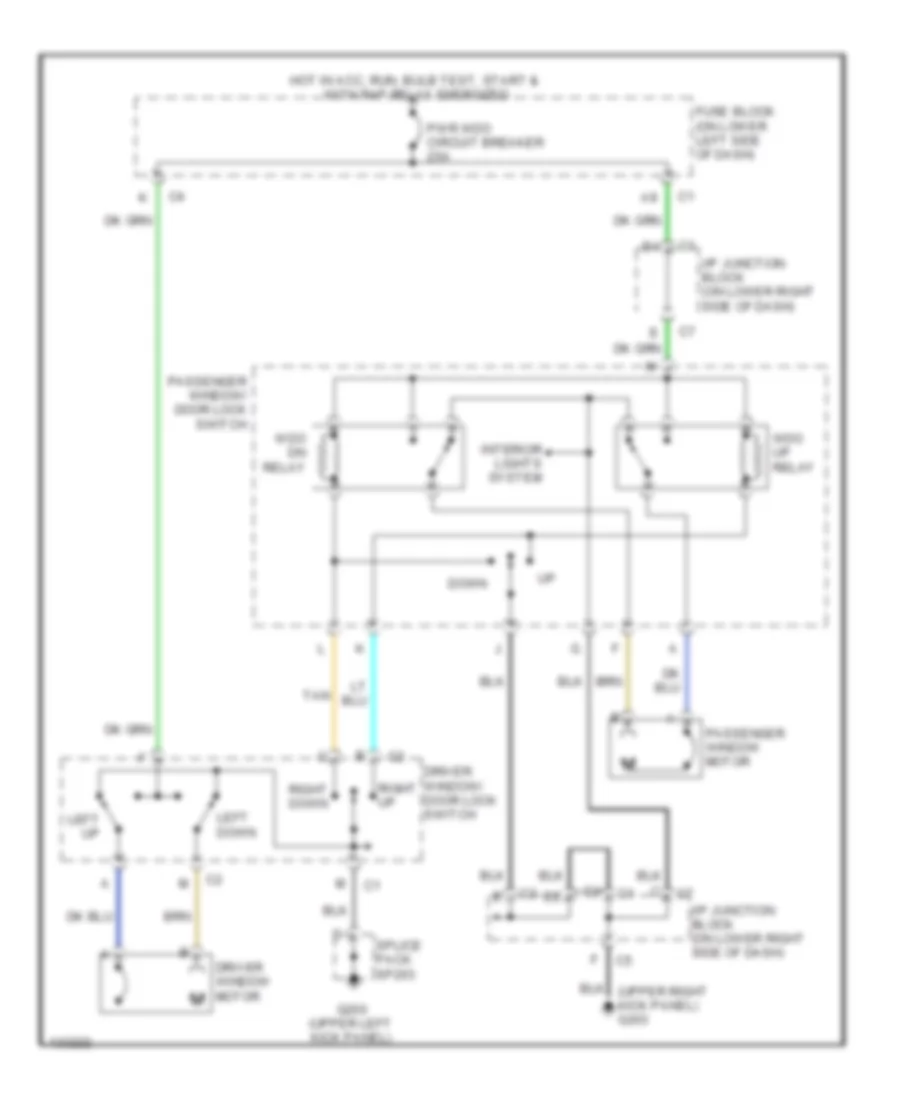
- Cargo door
- Center high mounted stoplamp
- Compressor leveling module
- G305 (right "b" pillar)
- G308 (left "b" pillar)
- G415 (on spare tire hoist bracket) (w/o rear lamps bussing block)
- G998 (rear corner of right rear window)
- Hvac control module
- Left back-up lamp
- Left cargo door ajar switch
- Left cargo rear window defogger grid
- Left door contactor
- Left license lamp
- Left liftgate ajar switch
- Left rear heated seat module
- Left rear mini wedge (door jamb switch)
- Left rear tail/ stoplamp
- Left rear turn signal lamp
- Left rear window/ door lock switch
- Liftgate
- Liftgate key switch
- Liftglass ajar switch
- Nca
- Rear accessory power outlet
- Rear window defogger grid
- Rear window wiper module
- Right back-up lamp
- Right cargo door ajar switch
- Right cargo rear window defogger grid
- Right door contactor
- Right license lamp
- Right liftgate ajar switch
- Right rear heated seat module
- Right rear mini wedge (door jamb switch)
- Right rear tail/ stoplamp
- Right rear turn signal lamp
- Right rear window/ door lock switch
- S410
- S415
- S420
- Sp410
- Sp410a
- Suburban/ yukon xl
- Suspension control module
- W/ecc- auto
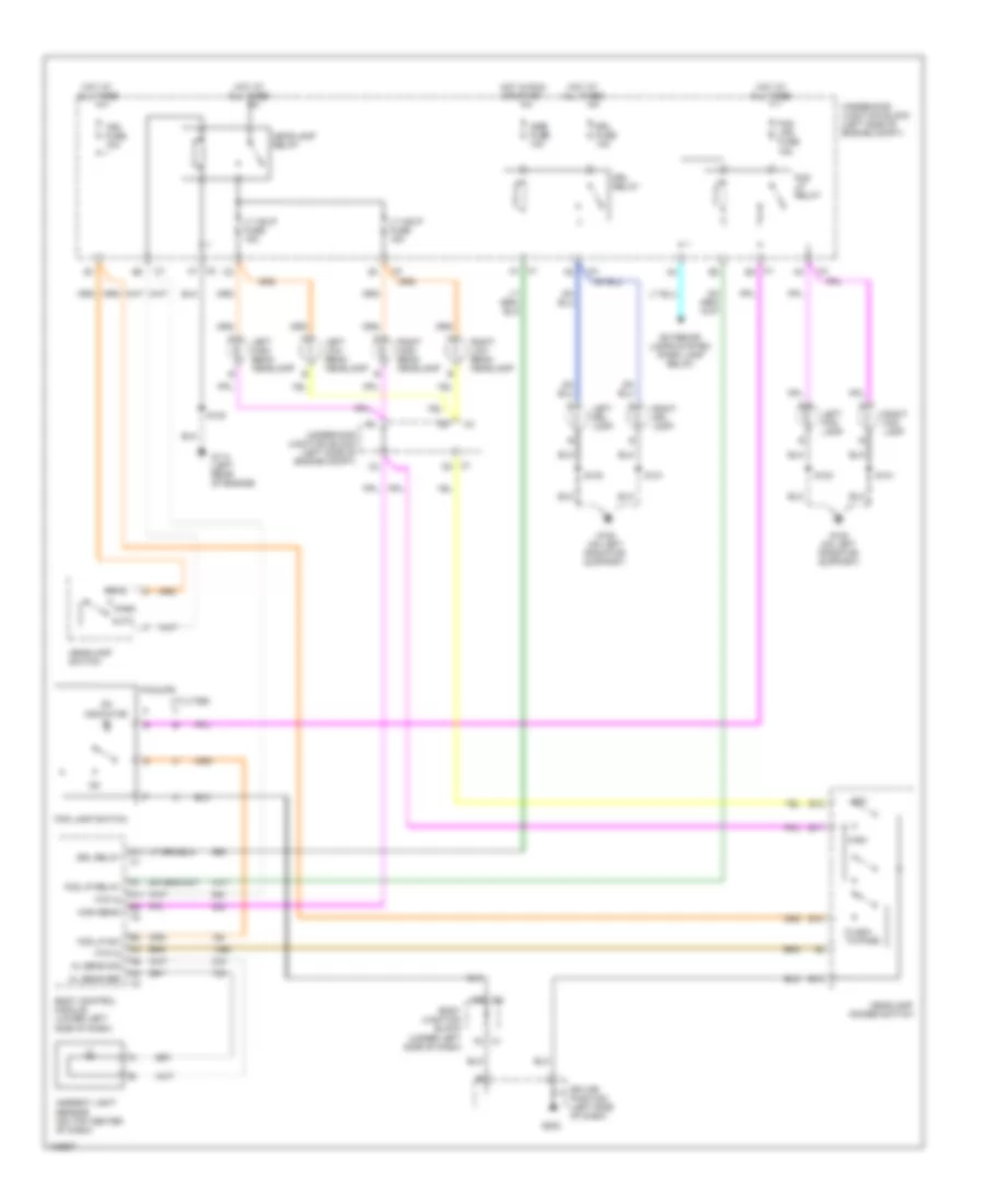
HEADLIGHTS
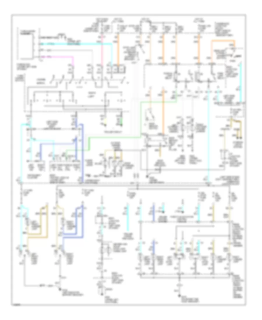
Headlight Wiring Diagram for GMC Cab & Chassis Sierra 2001 3500
List of elements for Headlight Wiring Diagram for GMC Cab & Chassis Sierra 2001 3500:
- A11
- Al sens ref
- Al sens sig
- Ambient light sensor (on top center of dash)
- Auto
- Body control module (lower left side of dash)
- Body junction block (under left side of dash)
- C1 b4
- C1 d3
- C1 f7
- C2 f7
- Drl fuse 10a
- Drl relay
- E10
- E11
- E12
- E13
- Exterior lamps system (park lamp relay)
- F2 c1
- Flash- to-pass
- Fog lamp switch
- Fog lp relay
- Fog lp sw
- Fog lps fuse 15a
- Ftp in
- G108 (on left radiator support)
- G114 (left rear of engine)
- G202
- Head
- Headlamp dimmer switch
- Headlamp relay
- Headlamp switch
- High
- High beam
- Hot at all times
- Hot in run or start
- Igne fuse 10a
- Left drl lamp
- Left fog lamp
- Left high beam headlamp
- Left low beam headlamp
- Low
- Lt hdlp fuse 15a
- On indicator
- Park
- Pickups
- Right drl lamp
- Right fog lamp
- Right high beam headlamp
- Right low beam headlamp
- S100
- S101
- S102
- Splice pack 203 (left side of dash)
- Tbc fuse 10a
- Underhood junction block (left side of engine compt)
- Utilities
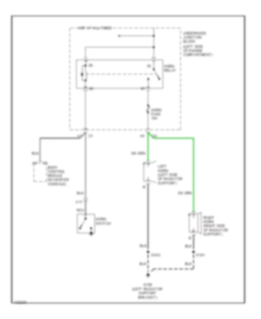
HORN
Horn Wiring Diagram for GMC Cab & Chassis Sierra 2001 3500
List of elements for Horn Wiring Diagram for GMC Cab & Chassis Sierra 2001 3500:
- (left side of engine compartment)
- A11
- C1 body control module (in center console)
- G108 (left radiator support bracket)
- Horn fuse 15a
- Horn relay
- Horn switch
- Hot at all times
- Left horn (left side of radiator support)
- Nca
- Right horn (right side of radiator support)
- S101
- S10o
- Underhood junction block
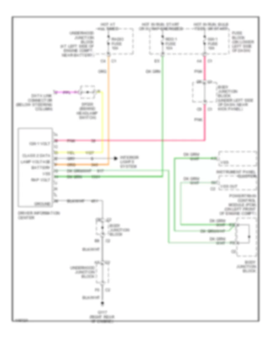
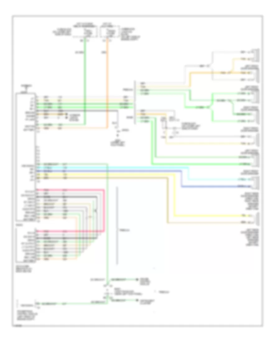
INSTRUMENT CLUSTER
Driver Information Center Wiring Diagram for GMC Cab & Chassis Sierra 2001 3500
List of elements for Driver Information Center Wiring Diagram for GMC Cab & Chassis Sierra 2001 3500:
- Battery
- Body junction block
- Body junction block (under left side of dash, near kick panel)
- Class 2 data
- Data link connector (below steering column)
- Driver information center
- Fuse block (on lower left side of dash)
- G117 (right rear of engine)
- Ground
- Hot at all times
- Hot in run, bulb test, or start
- Hot in run, start or w/ rap energized
- Ign 1 fuse 10a
- Ign 1 volt
- Instrument panel cluster
- Interior lights system
- Lamp voltage
- Pnk
- Powertrain control module (pcm) (on left front of engine compt)
- Radio fuse 10a
- Rap volt
- Rdo 1 fuse 10a
- Sp205 (behind headlamp switch)
- Underhood junction block
- Underhood junction block (at left side of engine compt, near battery)
- Vss
- Vss out
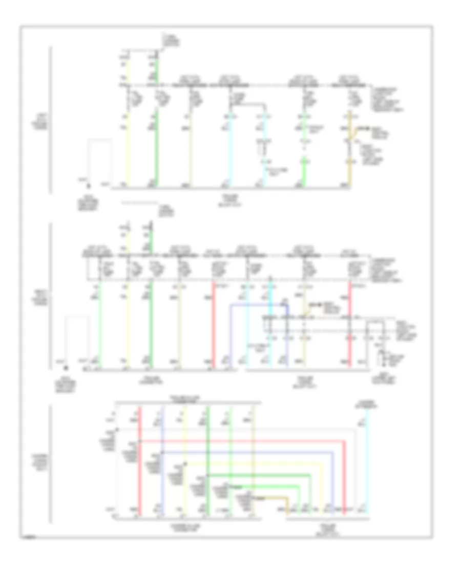
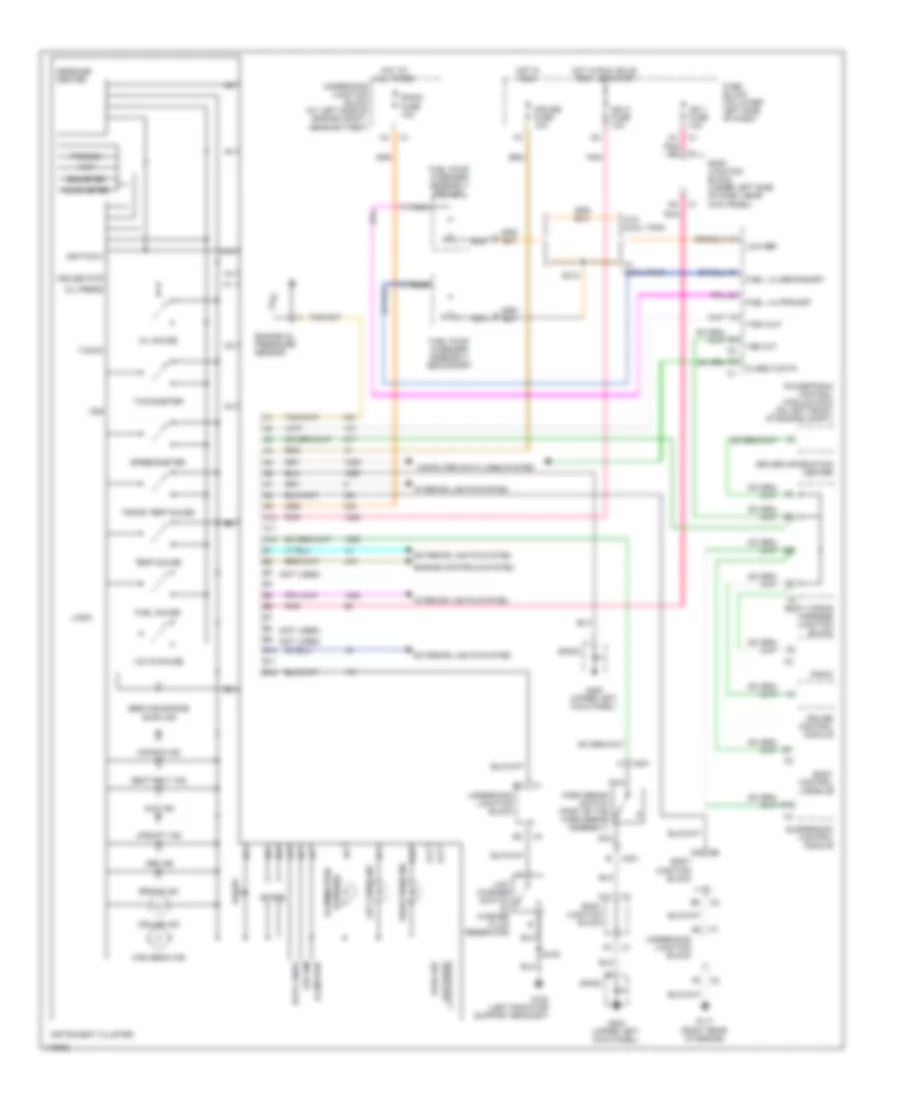
Instrument Cluster Wiring Diagram for GMC Cab & Chassis Sierra 2001 3500
List of elements for Instrument Cluster Wiring Diagram for GMC Cab & Chassis Sierra 2001 3500:
- (not used)
- 4wd ind
- A10
- A11
- A12
- A4 pnk d8
- Abs ind
- Air bag ind
- B10
- B11
- B12
- Body control module
- Body junction block
- Body junction block (under left side of dash, near kick panel)
- Body wiring harness junction block
- Brake ind
- C201
- Class 2 data
- Computer data lines system
- Cruise control module
- Cruise fuse 10a
- Cruise ind
- Cruise pwr
- Data lines
- Driver information center
- Engine controls system
- Engine oil pressure sensor
- Exterior lights system
- Fuel gauge
- Fuel lvl-primary
- Fuel lvl-secondary
- Fuel pump & sender assembly- primary
- Fuel pump & sender assembly- secondary
- Fuse block (on lower left side of dash)
- G108 (left radiator support bracket)
- G117 (right rear of engine)
- G200 (upper left kick panel)
- High beam ind
- Hot at all times
- Hot in run
- Hot in run, bulb test, or start
- Hour meter
- Ign 1 fuse 10a
- Ign o fuse 10a
- Ignition 0
- Illum pwr
- Illumination (6 bulbs)
- Instrument cluster
- Interior lights system
- Led dim
- Left turn ind
- Logic
- Low ref
- Low wash
- Low washer switch (in washer fluid reservoir)
- Message center
- Nca
- Odometer
- Oil gauge
- Oil press
- Park brake switch (part of the park brake assembly)
- Park sw
- Pnk
- Powertrain control module (pcm) (on left front of engine compt)
- Prnd321
- Radio
- Radio fuse 10a
- Right turn ind
- S100
- S312
- Seat belt ind
- Service engine soon ind
- Sp203
- Spare
- Speedometer
- Suspension control module
- Tach out
- Tacho
- Tachometer
- Temp gauge
- Trans temp gauge
- Trip
- Underhood junction block
- Underhood junction block (at left side of engine compt, near battery)
- Upshift ind
- Volts gauge
- Vss
- Vss out
- W/ dual tank
- W/o dual tank
INTERIOR LIGHTS
Courtesy Lamps Wiring Diagram, Base for GMC Cab & Chassis Sierra 2001 3500
List of elements for Courtesy Lamps Wiring Diagram, Base for GMC Cab & Chassis Sierra 2001 3500:
- (not used)
- A10
- A12
- B (not used)
- B1 (not used)
- B12
- Body control module (on lower left side of dash, below steering column)
- Body junction block (under left side of dash, near left kick panel)
- C10
- C11
- C12
- C9 c2
- Cargo lamp
- Cargo lamp switch
- Cargo lp sw
- Courtesy lamp relay
- Ctsy lp fuse 15a
- Ctsy lp rly
- D (not used)
- Dome lamp
- Dome lamp defeat switch
- Dome lamp switch
- Dome lp dft
- Dome lp sw
- Fuse block (on lower left side of dash)
- G132 (right front of engine block)
- G200 (upper left kick panel)
- Headlamp & panel dimmer switch
- Hot at all times
- Inadvert rly
- Inadvertant power relay
- Lamp request
- Left i/p courtesy lamp
- Left mini wedge (door jamb switch)
- Lt door jamb
- Right i/p courtesy lamp
- Right mini wedge (door jamb switch)
- Rt dr jamb
- S102
- Sp203
- Tan
- Underhood junction block (on left side of engine compt, near battery)
- Underhood off lamp assembly
Courtesy Lamps Wiring Diagram, Up Level for GMC Cab & Chassis Sierra 2001 3500
List of elements for Courtesy Lamps Wiring Diagram, Up Level for GMC Cab & Chassis Sierra 2001 3500:
- (not used)
- A10
- A11
- B12
- Body control module (on lower left side of dash, below steering column)
- Body junction block (under left side of dash, near left kick panel)
- C10
- C12
- C9 c2
- Cargo lamp
- Cargo lamp switch
- Cargo lp sw
- Courtesy lamp relay
- Ctsy lp fuse 15a
- Ctsy lp rly
- D10
- Dome lamp
- Dome lamp defeat switch
- Dome lamp switch
- Dome lp dft
- Dome lp sw
- Fuse block (on lower left side of dash)
- G132 (right front of engine block)
- G200 (upper left kick panel)
- G203 (upper right kick panel)
- Headlamp & panel dimmer switch
- Hot at all times
- I/p compart- ment lamp
- I/p junction block (on lower right side of dash)
- Inadvert rly
- Inadvertent power relay
- Lamp request
- Left front door courtesy lamp
- Left i/p courtesy lamp
- Reading lamps
- Right front door courtesy lamp
- Right i/p courtesy lamp
- S102
- Sp203
- Underhood junction block (on left side of engine compt, near battery)
- Underhood lamp assembly off
Instrument Illumination Wiring Diagram for GMC Cab & Chassis Sierra 2001 3500
List of elements for Instrument Illumination Wiring Diagram for GMC Cab & Chassis Sierra 2001 3500:
- (4 bulbs)
- (6 bulbs)
- A12
- Ashtray lamp
- Auto
- B12
- B5 c1
- Base
- Body control module (on lower left side of dash, below steering column)
- Body junction block (under left side of dash, near left kick panel)
- C10
- Dim in
- Driver heated seat switch
- F12
- Fog/ cargo lamp switch
- Fuse block (on lower left side of dash)
- G200 (upper left kick panel)
- G203 (upper right kick panel)
- Head
- Headlamp & panel dimmer switch
- Hot at all times
- Hvac control module
- I/p dim
- I/p junction block (on lower right side of dash)
- Illum fuse 10a
- Inflatable restraint i/p module switch
- Instrument cluster
- Int prk fuse 10a
- Left power door lock switch
- Left power window switch
- Left power window/ door lock switch
- Nca
- Parade mode
- Park
- Park lp rly
- Park lp sig
- Park lps fuse 30a
- Parklamp relay
- Power mirror switch
- Radio
- Roof beacon switch
- Select- able ride switch
- Sp203
- Traction assist switch
- Transfer case shift control switch
- Underhood junction block (on left side of engine compt, near battery)
- Up level
MEMORY SYSTEMS
Driver's Memory Seat Wiring Diagram for GMC Cab & Chassis Sierra 2001 3500
List of elements for Driver's Memory Seat Wiring Diagram for GMC Cab & Chassis Sierra 2001 3500:
- (under driver's seat)
- A/t shift lock
- A3 a3
- B7 c1
- Back
- Batt pos volt
- Btsi fuse 10a
- Driver seat adjustment switch
- Driver window door lock switch
- Front vert dn
- Front vert up
- Frt dn
- Frt up
- Ft vert dn ctrl
- Ft vert pos sen
- Ft vert up ctrl
- Fuse block (lower left side of dash)
- Fwd
- G c4
- G304 (under driver's seat)
- Ground
- Hall effect sensor
- Horiz fwd
- Horiz fwd ctrl
- Horiz pos sen
- Horiz rwd
- Horiz rwd ctrl
- Hot at all times
- Hot in run
- Ign 3 fuse 10a
- Ign 3 volt
- Memory 1 sw
- Memory 2 sw
- Memory seat module (underside of driver's seat)
- Memory seat switch
- Memory set sw
- Mir/lock fuse 3a
- Nca
- Not used
- Rcl 1
- Rcl 2
- Rcl back
- Rcl fwd
- Rear dn
- Rear up
- Rear vert dn
- Rear vert up
- Recline fwd
- Recline fwd ctrl
- Recline pos sen
- Recline rwd
- Recline rwd ctrl
- Recliner motor
- Red
- Rr vert dn ctrl
- Rr vert pos sen
- Rr vert up ctrl
- S308
- S310
- S314
- S315
- S316
- Seat front verticle motor (under driver's seat)
- Seat horizonal motor (under driver's seat)
- Seat rear vertical motor (under driver's seat)
- Seats circuit breaker 25a
- Set
- Shift interlock system
- Tan
- Underhood junction block (at left side of engine compartment, near battery)
POWER DISTRIBUTION
Power Distribution Wiring Diagram (1 of 4) for GMC Cab & Chassis Sierra 2001 3500
List of elements for Power Distribution Wiring Diagram (1 of 4) for GMC Cab & Chassis Sierra 2001 3500:
- (base pickup (uplevel pickup, utilities)
- (diagram 1 of 4)
- (not used)
- (on left side of engine compt) underhood junction block
- (right rear side of cargo area)
- (under left side of dash) body junction block
- (upper left kick panel)
- A/c compressor relay
- A/c fuse 10a
- Abs fuse 60a
- Accessory power outlet
- Accessory power outlet (console)
- Air fuse 30a
- Atc fuse 20a
- Audio amplifier
- Automatic transmission control module (allison)
- Aux pwr fuse 20a
- B12
- B12 d2
- Base
- Bat
- Battery cable junction block
- Body control module
- C1 f2
- C10
- C12
- Cigar fuse 15a
- Cigar lighter
- Ctsy lp fuse 15a
- D10
- D11
- D12
- Data link connector (dlc)
- Daytime running lamp (drl) relay
- Diesel only
- Dimmer switch
- Driver infor- mation center (dic)
- Driver seat
- Drl fuse 10a
- E nca
- E10
- Ecm b fuse 20a
- Electronic brake control module (ebcm)
- Engine control module (ecm)/ powertrain control module (pcm)
- F10
- F11
- F12
- Fog lps fuse 15a
- Foglamp relay
- From air fuse b
- From fuse l block (diagram 4 of 4)
- From rap fuse c (diagram 1 of 4)
- Front blower motor resistor assembly
- Front passenger window/door lock switch
- Frt hvac fuse 30a
- Fuel pump relay
- Fusible link (10 ga- red)
- G200
- G203 (upper right kick panel)
- G405
- Generator
- Generator (w/ dual diesel only)
- Hazard fuse 20a
- Headlamp dimmer switch
- Headlamp relay
- Horn relay
- Hvac control module
- I/p junction block
- Inadvertent power relay
- Instrument panel cluster (ipc)
- L nca
- Left battery
- Nca
- Park lamps fuse 30a
- Parklamp relay
- Passenger seat
- Power sunroof
- Power takeoff (pto) relay
- Pwr wdo cb 25a
- Radio
- Radio fuse 15a
- Rap 2 fuse 50a
- Rap 2 relay
- Rap fuse 50a
- Rdo amp fuse 25a
- Rear accessory power outlet
- Red
- Remote control door lock receiver
- Right rear defogger relay
- Right rear heated seat switch
- Right rear window/door lock switch
- Roof beacon relay
- Roof beacon switch
- Secondary air injection (air) pump relay
- Seo 1 fuse 15a
- Seo 2 fuse 30a
- Sp203
- Sp410
- Starter solenoid
- Stop lps fuse 20a
- Stoplamp switch
- Sunroof module
- Tbc fuse 10a
- To auxiliary battery relay (diagram 3 of 4)
- To ecm b fuse (diagram 1 of 4)
- To fuse block (mir/lock fuse) (diagram 4 of 4)
- To ign 1 relay (diagram 3 of 4)
- To ign a fuse (diagram 2 of 4)
- To park lamps fuse (diagram 1 of 4)
- Transfer case encoder motor
- Transfer case shift module
- Turn signal/ multi- function switch
- Under- hood junction block (on left side of engine compt)
- Under- hood junction block (on left side of engine)
- Uplevel
- Vehicle interface unit (onstar)
Power Distribution Wiring Diagram (2 of 4) for GMC Cab & Chassis Sierra 2001 3500
List of elements for Power Distribution Wiring Diagram (2 of 4) for GMC Cab & Chassis Sierra 2001 3500:
- (4.3l)
- (a/t)
- (all others)
- (canada built)
- (diesel)
- (gas)
- (m/t)
- (not used)
- (others)
- A/c clutch relay
- A10
- A13
- Acc
- Air bag fuse 15a
- Automatic transmission
- B/u lp fuse 25a
- B11
- Back-up lamp switch (part of park/ neutral position switch (a/t))
- Body control module
- Body junction block (under left side of dash)
- Bulb test
- C1 a1
- C10
- C2 f6
- Camshaft position (cmp) sensor (4.3l)
- Cellular phone ready wiring
- Clutch pedal position switch (m/t)
- Compressor levelling module
- Compressor motor relay
- Crank fuse 10a
- Cruise control module
- Cruise control on/off switch
- Cruise fuse 10a
- D (gas) (diesel)
- Driver information center (dic)
- Drl relay
- E11
- E6 (not used)
- Emergency light relay
- Eng 1 fuse 10a
- Engine control module (ecm) (diesel)
- Engine control module (ecm)/ powertrain control module (pcm)
- Evaporative emission (evap) canister purge solenoid
- Evaporative emission (evap) canister vent solenoid
- Ext lps fuse 10a
- F10
- F11
- From cigar e
- Fuel heater (diesel)
- Fuse (diagram 1 of 4)
- Fuse block (on lower left side of dash)
- Gas only
- Heated oxygen sensor (ho2s) (bank 1 sensor 1) (gas)
- Heated oxygen sensor (ho2s) (bank 1 sensor 2) (gas)
- Heated oxygen sensor (ho2s) (bank 2 sensor 1) (gas)
- Heated oxygen sensor (ho2s) (bank 2 sensor 2) (gas)
- Ign 1 fuse 10a
- Ign a fuse 40a
- Ign b fuse 50a
- Ign c fuse 20a
- Ign e fuse 10a
- Ign o fuse 10a
- Ignition switch
- Inflatable restraint i/p module switch (pickup only)
- Inflatable restraint sensing & diagnostic module
- Inside temperature sensor assembly
- Instrument panel cluster (ipc)
- Intake air temperature (iat)/ mass air flow (maf) sensor
- Nca
- Nca c
- Nca f
- O2 a fuse 15a fuel ht fuse 15a
- O2 b fuse 15a ecm 1 fuse 10a
- Off
- Outside rearview mirror
- Park/ neutral position switch (a/t)
- Pnk
- Rear defog relay
- Rear window wiper module
- Rear wiper washer switch
- Red
- Rr hvac fuse 30a
- Rr wiper fuse 15a
- Rr wpr fuse 25a
- Rtd module fuse 30a
- Run
- Secondary air injection (air) pump relay
- Secondary fuel pump relay
- Selectable ride switch
- Seo ign fuse 10a
- Seq accy fuse 10a
- Start
- Starter relay
- Stud 1
- Stud 1 fuse 40a
- Stud 2
- Stud 2 fuse 30a
- Suspension control module
- To htr/ a/c fuse (diagram 3 of 4)
- To i/p junction block (diagram 3 of 4)
- To ign 1 relay (diagram 3 of 4)
- To retained accessory power relay (diagram 4 of 4)
- Traction assist switch
- Trailer connector
- Transfer case shift control switch
- Turn fuse 20a
- Turn signal/ multi- function switch
- Under- hood junction block (on left side of engine compt)
- Underhood junction block (on left side of engine compt)
- Vehicle interface unit (viu)
- Windshield washer switch
- Windshield wiper motor module
- Ws wiper fuse 25a
Power Distribution Wiring Diagram (3 of 4) for GMC Cab & Chassis Sierra 2001 3500
List of elements for Power Distribution Wiring Diagram (3 of 4) for GMC Cab & Chassis Sierra 2001 3500:
- (4.3l)
- (all other gas)
- (auto ecc)
- (base)
- (diesel)
- (diesel) (gas)
- (engine harness) s199
- (except 4.3l)
- (gas)
- (manual)
- (on lower left side of dash) fuse block
- (other pnk
- (other)
- (uplevel pickups & utilities)
- 4.3l
- 4wd fuse 15a
- A11
- Air temperature actuator
- All other gas
- Auxiliary battery relay
- B h
- B j
- B10
- Blower motor switch (manual)
- Brake fuse 10a
- C10
- C11
- C12
- C2 c1
- Clutch pedal position switch
- Compressor leveling relay relay
- D10
- Diesel
- E10
- E12
- Ecm 1 fuse 10a ecm prv fuse 15a
- Electronic brake control module (ebcm)
- Engine control module (ecm)/
- Engine control module (ecm)/ powertrain control module (pcm)
- Etc fuse 15a
- From cruise g
- From eng 1 fuse (diagram 2 of 4) from ecm b fuse (diagram 1 of 4)
- From fuse link (diagram 1 of 4)
- From ign c f
- From rr hvac fuse (diagram 2 of 4)
- Front axle actuator
- Front passenger heated seat switch
- Fuel injector 1
- Fuel injector 2
- Fuel injector 3
- Fuel injector 4
- Fuel injector 5 (all gas)
- Fuel injector 6
- Fuel injector 7 (except 4.3l)
- Fuel injector 8
- Fuse (diagram 2 of 4)
- G114 (left rear of engine)
- Gas
- Gas)
- Heater auxiliary blower motor resistor
- Htr/ a/c fuse 25a
- Hvac 1 fuse 10a
- Hvac control module
- I/p junction block (on lower right side of dash)
- Ign 1 relay
- Ign 3 fuse 10a
- Ignition coil
- Ignition coil 1
- Ignition coil 2
- Ignition coil 3
- Ignition coil 4
- Ignition coil 5
- Ignition coil 6
- Ignition coil 7
- Ignition coil 8
- Ignition coil driver
- Inj a fuse 15a
- Inj b fuse 25a 15a
- Injector control module (icm)
- Left front heated seat switch
- Left rear heated seat module
- Mega fuse 125a
- Memory seat module (except pickup)
- Memory seat module (pickup only)
- Mode actuator
- Nca
- Pnk
- Powertrain control module (pcm) (4.3l)
- Recirculation actuator
- Red
- Right battery
- Right rear heated seat module
- S104
- S152 (eng pnk harn)
- S154 (eng pnk harn)
- Stoplamp switch
- Suspension control module
- To a/c auxiliary blower motor resistor assembly (diagram 4 of 4)
- Transfer case shift control module
- Under- hood junction block (on left side of engine compt)
Power Distribution Wiring Diagram (4 of 4) for GMC Cab & Chassis Sierra 2001 3500
List of elements for Power Distribution Wiring Diagram (4 of 4) for GMC Cab & Chassis Sierra 2001 3500:
- (except pickup)
- (not used)
- (pickup only)
- (pickup)
- (utilities)
- A/c auxiliary blower motor resistor assembly
- A10
- Air temperature actuator
- Air temperature sensor
- Base
- Base pickup
- Base utility
- Body control module (bcm)
- Body junction block fuse block (under left side of dash)
- C1 b4
- C1 c9
- C1 e7
- C14
- C4 k
- C4 l
- C6 c
- C7 e
- Door lock fuse 20a
- Door lock relay
- Door unlock relay
- Driver door lock switch
- Driver door unlock relay (uplevel only)
- Driver memory seat switch
- Driver seat adjuster switch
- Driver window/ door lock switch
- F11
- From fuse block (diagram 2 of 4)
- From i/p junction block (diagram 3 of 4)
- From rap fuse d (diagram 1 of 4)
- Front auxiliary hvac control assembly
- Front passenger door lock switch
- Front passenger seat adjuster switch
- Front passenger window/ door lock switch
- Fuse block (on lower left side of dash)
- I/p junction block
- Instrument cluster & sound systems
- Left full feature seat
- Left power door lock switch
- Left power seat
- Left power window/ door lock switch
- Memory seat switch
- Mir/ lock fuse 3a
- Mode actuator
- Nca
- Outside rear view mirror switch
- Pickup
- Pwr wdo cb 25a
- Radio
- Rap 2 fuse 10a
- Rdo 1 fuse 10a
- Rear auxiliary hvac control assembly
- Rear cargo door lock switch
- Rear hvac control module
- Red
- Relays
- Retained accessory power relay
- Right full feature seat
- Right power seat
- Seats circuit breaker 25a
- To rap 2 relay (diagram 1 of 4)
- Uplevel & 4-door
- Uplevel all
- Utilities
- Utility only
- Vehicle interface unit (viu)
- W/ auto ecc
- W/ heat & a/c
- W/ heat or a/c
- W/ sunroof
- W/o sunroof
POWER DOOR LOCKS
Power Door Lock Wiring Diagram, Base for GMC Cab & Chassis Sierra 2001 3500
List of elements for Power Door Lock Wiring Diagram, Base for GMC Cab & Chassis Sierra 2001 3500:
- (lower right side of i/p) i/p junction block
- (upper left i/p, at "a" pillar)
- 87a
- A12
- B11
- B12
- Body control module (on lower left side of dash, below steering column)
- Body junction block (near left kick panel)
- C1 a11
- C1 b8
- C1 f4
- C211
- C4 a
- C4 d
- C4 m
- Door lock relay
- Door unlock relay
- Dr lk rly
- Dr lock fuse 20a
- Dr unlk rly
- Driver door lock actuator
- Driver door lock switch
- Drv dr unlk rly
- E10
- F12
- Fuse block (on lower left side of dash)
- G200
- G200 (upper left kick panel)
- Hot at all times
- Ign key sig
- Ignition key alarm switch (part of steering column assembly)
- Instrument panel cluster
- Lock
- Lock fuse 15a
- Mir/ lock fuse 3a
- Nca
- Passenger door lock actuator
- Passenger door lock switch
- Powertrain control module (left front inside of engine compartment)
- Splice pack
- Tan
- Unlock
- Unlock fuse 15a
- Unlock jmpr fuse 30a
- Vss
- Vss signal
Power Door Lock Wiring Diagram, Up Level for GMC Cab & Chassis Sierra 2001 3500
List of elements for Power Door Lock Wiring Diagram, Up Level for GMC Cab & Chassis Sierra 2001 3500:
- (lower right side of i/p) i/p junction block
- (upper left kick panel)
- 87a
- A12
- B11
- B12
- Battery
- Body control module (on lower left side of dash, below steering column)
- Body junction block (near left kick panel)
- C1 a11
- C1 a12
- C1 b8
- C1 f2
- C1 f4
- C11
- C211
- C4 a
- C4 d
- C4 m
- Door lock relay
- Door unlock relay
- Dr lock fuse 20a
- Driver door lock actuator
- Driver door unlock relay
- Driver window/door lock switch
- E10
- F10
- F12
- Fuse block (on lower left side of dash)
- G200
- G200 (upper left kick panel)
- Ground
- Hot at all times
- I/p junction block (on lower right side of i/p)
- Ign key switch
- Ignition key alarm switch (part of steering column assembly)
- Instrument panel cluster
- Lf dr unlk in
- Lock
- Lock fuse 15a
- Lock in
- Mir/lock fuse 3a
- Nca
- Passenger door lock actuator
- Passenger window/door lock switch
- Powertrain control module (left front inside of engine compartment)
- Remote control door lock receiver (behind top center of dash)
- Serial data
- Splice pack
- Srl data
- Tan
- Tbc fuse 10a
- Underhood junction block (on left side of engine compt)
- Unlock
- Unlock fuse 15a
- Unlock in
- Vss
- Vss signal
POWER MIRRORS
Electrochromic Mirror Wiring Diagram for GMC Cab & Chassis Sierra 2001 3500
List of elements for Electrochromic Mirror Wiring Diagram for GMC Cab & Chassis Sierra 2001 3500:
- (behind left side of dash)
- (w/ onstar)
- (w/o onstar)
- (w/o onstar) (w/ onstar)
- A/t
- B/u lp fuse 25a
- Back-up lamp switch (on left side of trans- mission)
- Back-up lamp switch (part of park/neutral position switch) (on left side transmission)
- Body junction block
- C/m
- C1 a11
- C1 a4
- C1 b10
- C1 d8
- C1 e12
- C1 f2
- C11 a
- C11 b
- C2 a9
- C2 f
- C2 f9
- C6 a
- C6 j
- C6 m
- Compass
- Dim fd
- Dim rtn
- Driver outside rearview mirror (utility)
- Electro-chromic
- Fuse block (on lower left side of dash)
- G202
- Hot in run or start
- Ign 1 fuse 10a
- Inside rearview mirror
- M/t
- Nca
- Off
- Others
- Outside air temperature sensor (behind center grille)
- Photo sensor
- Pickup w/ compass & outside temperature
- Pnk
- Selector switch
- Temp
- Veh b/u fuse 15a
Power Mirror Wiring Diagram for GMC Cab & Chassis Sierra 2001 3500
List of elements for Power Mirror Wiring Diagram for GMC Cab & Chassis Sierra 2001 3500:
- C1 m
- C2 g
- Defogger system
- Down
- Driver outside rearview mirror
- Driver power window/ door lock switch
- Fuse block
- G200
- Heating element
- Hot at all times
- Interior lights system
- L c4
- Left
- Left/ right motor
- Memory systems
- Mir/ clock fuse 3a
- Nca
- Outside rearview mirror switch
- Passenger outside rearview mirror
- Right
- Sp203 (upper left kick panel)
- Up/ down motor
POWER SEATS
6-Way Power Seat Wiring Diagram for GMC Cab & Chassis Sierra 2001 3500
List of elements for 6-Way Power Seat Wiring Diagram for GMC Cab & Chassis Sierra 2001 3500:
- A10
- Back
- Body junction block
- C14
- Driver seat adjuster switch
- Front dn
- Front up
- Fuse block (on lower left side of dash)
- Fwd
- G300 (under driver's seat)
- Hot at all times
- Passenger power seat switch
- Rear dn
- Rear up
- S307
- Seat circuit breaker 25a
- Seat front vertical motor
- Seat horizontal motor
- Seat rear vertical motor
- Tan
Front Seat Heater Wiring Diagram for GMC Cab & Chassis Sierra 2001 3500
List of elements for Front Seat Heater Wiring Diagram for GMC Cab & Chassis Sierra 2001 3500:
- Body junction block (under left side of dash, near kick panel)
- D12
- Driver heated seat relay (in driver seat)
- Driver heated seat thermistor
- Driver seat heated switch
- Driver seat heater element (seat back)
- Driver seat heater element (seat)
- Fuse block (on lower left side of dash)
- G200 (upper left kick panel)
- G203 (upper right kick panel)
- G300 (under driver's seat)
- Gnd
- Heater on ind
- Hot at all times
- Hot in run
- I/p junction block (lower right side of dash)
- Ign 3 fuse 10a
- Illum
- Interior lights system
- Left power window/ door lock switch
- Nca
- Passenger heated seat relay (in passenger seat)
- Passenger heated seat switch
- Passenger heated seat thermistor
- Passenger seat heater element (seat back)
- Passenger seat heater element (seat)
- S308
- Sensor
- Seo 2 fuse 30a
- Solid state
- Sp203
- Underhood junction block (left side of dash, near kick panel)
Lumbar Wiring Diagram for GMC Cab & Chassis Sierra 2001 3500
List of elements for Lumbar Wiring Diagram for GMC Cab & Chassis Sierra 2001 3500:
- A10
- Body junction block
- C14
- Driver lumbar/ bolster switch
- Driver seat bolster m0tor
- Driver seat lumbar m0tor
- Fuse block (on lower left side of dash)
- G300 (under driver's seat)
- Hot at all times
- Out
- Pass- enger lumbar/ bolster switch
- Passenger seat bolster m0tor
- Passenger seat lumbar m0tor
- Pnk
- Power seats circuit
- S308
- S309
- S310
- S311
- Seat circuit breaker 25a
- Tan
POWER WINDOWS
Power Window Wiring Diagram, 2 Door for GMC Cab & Chassis Sierra 2001 3500
List of elements for Power Window Wiring Diagram, 2 Door for GMC Cab & Chassis Sierra 2001 3500:
- Down
- Driver window motor
- Driver window/ door lock switch
- Fuse block (on lower left side of dash)
- G200 (upper left kick panel)
- Hot in acc, run, bulb test, start & with rap relay energized
- I/p junction block (on lower right side of dash)
- Interior lights system
- Left down
- Left up
- Passenger window motor
- Passenger window/ door lock switch
- Pwr wdo circuit breaker 25a
- Right down
- Right up
- Splice pack sp203
- Tan
- Wdo dn relay
- Wdo up relay
Power Window Wiring Diagram, 4 Door for GMC Cab & Chassis Sierra 2001 3500
List of elements for Power Window Wiring Diagram, 4 Door for GMC Cab & Chassis Sierra 2001 3500:
- B12
- D12
- Down
- Driver window motor
- Driver window switch
- Front passenger window motor
- Front passenger window switch
- Fuse block (on lower left side of dash)
- G200 (upper left kick panel)
- G203 (upper right kick panel)
- G305 (right "b" pillar)
- G308 (left "b" pillar)
- Hot in acc, run, bulb test or w/rap relay energized
- Hot in acc, run, bulb test, start or w/rap relay energized
- I/p junction block (on lower right side of dash)
- Interior lights system
- Left front down
- Left front up
- Left rear down
- Left rear up
- Left rear window motor
- Left rear window switch
- Lockout
- Pwr wdo circuit breaker 25a
- Right front down
- Right front up
- Right rear down
- Right rear up
- Right rear window motor
- Right rear window switch
- Splice pack sp203
- Tan
- Window down relay
- Window up relay
RADIO
Radio Wiring Diagrams for GMC Cab & Chassis Sierra 2001 3500
List of elements for Radio Wiring Diagrams for GMC Cab & Chassis Sierra 2001 3500:
- Antenna
- Audio rtn
- Bare
- Base
- Battery
- Body junction block (near left kick panel)
- Cd player- remote play- back device
- Cruise control module
- D10
- D12
- Dim sig in
- Dim sig out
- Dimmer
- Drain
- E&c line
- Fuse block (on lower left side of dash)
- G200 (upper left kick panel)
- Ground
- Hot at all times
- Hot with rap relay energized
- I/p lamp
- Ignition
- Instrument cluster
- Interior lights system
- J c4
- Left front door speaker
- Left rear door speaker (crew cab) left rear speaker (except crew cab)
- Lf +
- Lf -
- Lr +
- Lr -
- Lt input
- Lt output
- Nca
- Pnk
- Powertrain control module (left front of engine compt)
- Premium
- R14 in
- R14 out
- Radio
- Radio fuse 15a
- Rdo i fuse 10a
- Rf +
- Rf -
- Right front door speaker
- Right rear door speaker (crew cab) right rear speaker (except crew cab)
- Rr +
- Rr -
- Rt input
- Rt output
- Sp203
- Tan
- Underhood junction block (on left side of engine compt)
- Vss signal
SHIFT INTERLOCKS
Shift Interlock Wiring Diagram for GMC Cab & Chassis Sierra 2001 3500
List of elements for Shift Interlock Wiring Diagram for GMC Cab & Chassis Sierra 2001 3500:
- (upper left kick panel)
- A/t shift lock control solenoid (on steering column)
- A16
- A17
- B/u lps fuse 25a
- Btsi fuse 10a
- G200
- Hot in run or start
- Memory systems
- Nca
- Park/ neutral position switch (left side of transmission)
- Pnk
- Splice pack
- Stoplamp switch (top of brake pedal)
- Underhood junction block
STARTING/CHARGING
6.0L
6.0L VIN U, Charging Wiring Diagram for GMC Cab & Chassis Sierra 2001 3500
List of elements for 6.0L VIN U, Charging Wiring Diagram for GMC Cab & Chassis Sierra 2001 3500:
- (2001 only)
- (left radiator support bracket) g108
- (not used)
- (on left front side of engine) battery cable junction block
- (right front of engine) g119
- 4.3l engine
- All other engines
- Battery
- Body wiring harness junction block (under left side of dash, near kick panel)
- Charge indicator control
- Computer data lines
- Fuse block (on lower left side of dash)
- G117 (right rear of engine)
- Generator
- Generator field duty cycle signal
- Hot in run & start
- Ign 1 fuse 10a
- Instrument cluster
- Left battery
- Message center
- Pnk
- Power distribution system
- Powertrain control module (pcm) or vehicle control module (vcm) (on left front of engine compartment)
- Red
- Serial data class 2
- Solid state
- Splice pack (sp205) (on left side of dash behind headlamp switch)
- Starter solenoid
- Voltmeter
Starting Wiring Diagram for GMC Cab & Chassis Sierra 2001 3500
List of elements for Starting Wiring Diagram for GMC Cab & Chassis Sierra 2001 3500:
- (in engine harness) s102
- (not used)
- (right front of engine block) g132
- 87a
- A/t
- Acc
- Battery cable junction block (on left front side of engine)
- Body wiring harness junction block (under left side of dash, near kick panel)
- C10
- Clutch pedal position switch (on top of clutch pedal bracket)
- Crank fuse 10a
- D11
- D12
- F10
- F11
- Fuse block (on lower left side of dash)
- G108 (left radiator support bracket)
- G119 (right front of engine)
- Ign a fuse 40a
- Ign c fuse 20a
- Ignition switch
- Left battery
- Lock
- M/t
- Nca
- Off
- Park/neutral position switch (on left side of transmission)
- Power distribution system
- Red
- Run
- Start
- Starter motor
- Starter motor relay
- Starter solenoid
- Starting/ charging system (charging circuit) (generator left)
- Starting/ charging system (charging circuit) (generator right) (diesel dual generator)
- Underhood junction block (at left side of engine compartment, near battery)
6.6L
6.6L VIN 1, Charging Wiring Diagram for GMC Cab & Chassis Sierra 2001 3500
List of elements for 6.6L VIN 1, Charging Wiring Diagram for GMC Cab & Chassis Sierra 2001 3500:
- (not used)
- (on left front side of engine) battery cable junction block
- Battery
- Body wiring harness junction block (under left side of dash, near kick panel)
- Charge indicator control
- Computer data lines
- Field duty cycle signal
- Fuse block (on lower left side of dash)
- G108 (left radiator support bracket)
- G117 (right rear of engine)
- G119 (right front of engine)
- Hot in run & start
- Ign 1 fuse 10a
- Instrument cluster
- Left battery
- Left generator
- Message center
- Pnk
- Power distribution system
- Powertrain control module (pcm) (on left front of engine compartment)
- Red
- Right generator
- Serial data class 2
- Solid state
- Splice pack (sp205) (on left side of dash behind headlamp switch)
- Starter solenoid
- Voltmeter
Starting Wiring Diagram for GMC Cab & Chassis Sierra 2001 3500
List of elements for Starting Wiring Diagram for GMC Cab & Chassis Sierra 2001 3500:
- (in engine harness) s102
- (not used)
- (right front of engine block) g132
- 87a
- A/t
- Acc
- Battery cable junction block (on left front side of engine)
- Body wiring harness junction block (under left side of dash, near kick panel)
- C10
- Clutch pedal position switch (on top of clutch pedal bracket)
- Crank fuse 10a
- D11
- D12
- F10
- F11
- Fuse block (on lower left side of dash)
- G108 (left radiator support bracket)
- G119 (right front of engine)
- Ign a fuse 40a
- Ign c fuse 20a
- Ignition switch
- Left battery
- Lock
- M/t
- Nca
- Off
- Park/neutral position switch (on left side of transmission)
- Power distribution system
- Red
- Run
- Start
- Starter motor
- Starter motor relay
- Starter solenoid
- Starting/ charging system (charging circuit) (generator left)
- Starting/ charging system (charging circuit) (generator right) (diesel dual generator)
- Underhood junction block (at left side of engine compartment, near battery)
8.1L
8.1L VIN G, Charging Wiring Diagram for GMC Cab & Chassis Sierra 2001 3500
List of elements for 8.1L VIN G, Charging Wiring Diagram for GMC Cab & Chassis Sierra 2001 3500:
- (2001 only)
- (left radiator support bracket) g108
- (not used)
- (on left front side of engine) battery cable junction block
- (right front of engine) g119
- 4.3l engine
- All other engines
- Battery
- Body wiring harness junction block (under left side of dash, near kick panel)
- Charge indicator control
- Computer data lines
- Fuse block (on lower left side of dash)
- G117 (right rear of engine)
- Generator
- Generator field duty cycle signal
- Hot in run & start
- Ign 1 fuse 10a
- Instrument cluster
- Left battery
- Message center
- Pnk
- Power distribution system
- Powertrain control module (pcm) or vehicle control module (vcm) (on left front of engine compartment)
- Red
- Serial data class 2
- Solid state
- Splice pack (sp205) (on left side of dash behind headlamp switch)
- Starter solenoid
- Voltmeter
Starting Wiring Diagram for GMC Cab & Chassis Sierra 2001 3500
List of elements for Starting Wiring Diagram for GMC Cab & Chassis Sierra 2001 3500:
- (in engine harness) s102
- (not used)
- (right front of engine block) g132
- 87a
- A/t
- Acc
- Battery cable junction block (on left front side of engine)
- Body wiring harness junction block (under left side of dash, near kick panel)
- C10
- Clutch pedal position switch (on top of clutch pedal bracket)
- Crank fuse 10a
- D11
- D12
- F10
- F11
- Fuse block (on lower left side of dash)
- G108 (left radiator support bracket)
- G119 (right front of engine)
- Ign a fuse 40a
- Ign c fuse 20a
- Ignition switch
- Left battery
- Lock
- M/t
- Nca
- Off
- Park/neutral position switch (on left side of transmission)
- Power distribution system
- Red
- Run
- Start
- Starter motor
- Starter motor relay
- Starter solenoid
- Starting/ charging system (charging circuit) (generator left)
- Starting/ charging system (charging circuit) (generator right) (diesel dual generator)
- Underhood junction block (at left side of engine compartment, near battery)
SUPPLEMENTAL RESTRAINTS
Supplemental Restraint Wiring Diagram for GMC Cab & Chassis Sierra 2001 3500
List of elements for Supplemental Restraint Wiring Diagram for GMC Cab & Chassis Sierra 2001 3500:
- A10
- A11
- A12
- A13
- A14
- A15
- A16
- A17
- A18
- Air bag fuse 15a
- Air bag indicator
- Class 2 serial data
- Data link connector (dlc) (partial) (under left side of dash, below steering column)
- Disable signal
- Fuse block (on lower left side of dash)
- G202
- Ground
- High control
- Hot in run & start
- Ign 1 fuse 10a
- Ignition
- Indicator control
- Inflatable restraint electronic frontal sensor (efs) (under front center of vehicle, near radiator support frame)
- Inflatable restraint i/p module disable switch
- Inflatable restraint ip module
- Inflatable restraint sensing & diagnostic module (under driver's seat)
- Inflatable restraint steering wheel module
- Inflatable restraint steering wheel module coil
- Instrument panel cluster (ipc)
- Interior lights system
- Junction block-body (under left side of dash, near left kick panel)
- Low control
- Nca
- Off
- Pnk
- Sensor ground
- Sensor signal
- Shorting bar
- Solid state
- Splice pack 205 (sp205) (on left side of dash, behind headlamp switch)
- Splice pack sp203 (sp203) (on top left side of dash, near "a" pillar)
TRANSMISSION
6.0L
6.0L VIN U, A/T Wiring Diagram, 4L80-E for GMC Cab & Chassis Sierra 2001 3500
List of elements for 6.0L VIN U, A/T Wiring Diagram, 4L80-E for GMC Cab & Chassis Sierra 2001 3500:
- (in engine harness)
- (not used) a
- (right rear of engine block) g103
- +5v
- 1-2 shift solenoid
- 1-2 ss
- 2-3 shift solenoid
- 2-3 ss
- 4wd circuit (transfer case & front axle switch)
- 4wd low
- A/t fluid pressure manual valve position switch
- A/t ss
- A12
- Abs system
- Automatic transmission (4l80-e)
- Automatic transmission input shaft speed sensor (4wd) (on transmission)
- Body control module (lower left side of dash, below steering column)
- Body relay block (under c1
- Brake fuse 10a
- Brk sw
- C11
- Cls 2 data
- D3, d2
- D4, d2
- Data link connector (under left side of dash)
- Ecm1 fuse 10a
- Ecmb fuse 20a
- Ect sig
- Engine coolant temperature sensor (front of left cylinder head)
- Except light duty w/ delphi ho2s
- Fluid temp sensor
- Frt axle sw
- G103 (right rear of engine block)
- Gnd
- Hot at all times
- Hot in run
- Hot in run & start
- Hot in run, bulb test & start
- Ign
- Ign0 fuse 10a
- Ign1 fuse 10a
- Instrument cluster
- Instrument panel cluster (ipc)
- Left end of dash)
- Left i/p fuse block (lower left side of dash)
- Light duty w/ delphi ho2s
- Lo ref
- Malfunction indicator lamp
- Mil ctrl
- Park/neutral position switch (left side of transmission)
- Pc sol hi
- Pc sol lo
- Pnk
- Powertrain control module (left front of engine compt)
- Press ctrl solenoid
- Prnd a
- Prnd b
- Prnd c
- Prnd p
- Range b
- Range c
- Red
- Red a
- Rev, lo
- S103
- S113
- Sens gnd
- Splice pack sp205 (left side of dash)
- Stoplight switch (top of brake pedal bracket)
- Tcc pwm
- Tcc pwm solenoid
- Tft sens sig
- Throttle position sensor (on throttle body assy)
- Tp sig
- Trans rng a
- Underhood fuse block (left side of engine c2 compt, near battery)
- Underhood fuse block (left side of engine compt, near battery)
- Vehicle speed sensor (2wd: left rear of transmission) (4wd: left side of transfer case)
- Vss adapter (4wd) (left side of trans)
- Vss hi
- Vss lo
- W/ traction assist
- W/o traction assist
Transfer Case Wiring Diagram, Selectable for GMC Cab & Chassis Sierra 2001 3500
List of elements for Transfer Case Wiring Diagram, Selectable for GMC Cab & Chassis Sierra 2001 3500:
- (left front of engine compt) (w/ allison trans) transmission control module
- (left front of engine compt) powertrain control module (gas engines) or engine control module (diesel)
- (on left front body mount) g110
- (under left side of dash) data link connector
- (w/ allison transmission)
- +8v ref
- +8v ref out
- 2-hi ind
- 4-hi ind
- 4-lo ind
- 4wd fuse 15a
- 4wd ind lamp
- 4wd sw (lo)
- 4wd sw sig
- 4wd whl lock
- Atc fuse 20a
- Auxiliary battery relay
- Body relay block (under c1
- C10
- C11
- C12
- C13
- C14
- C15
- C16
- Channel-a
- Channel-b
- Channel-c
- Channel-p
- Class ii data
- Ctrl
- D10
- D11
- D12
- D13
- D14
- D15
- D16
- Dsl (ecm) gas (pcm)
- Encoder logic
- Encoder motor
- Encoder rtn
- Front axle actuator
- Ft axle ctrl
- G110 (on left front body mount)
- G203 (upper left kick panel)
- Gnd
- Hot at all times
- Hot in run
- Hot in run & start
- Ign 3 (run)
- Ign1 fuse 10a
- Illumination lamp (2)
- Instrument panel cluster
- Interior lights system
- Left i/p fuse block (lower left side of dash)
- Left side of dash)
- Logic
- Module gnd
- Motor (ccw)
- Motor (cw)
- Nca
- Neutral ind
- Pnk
- Red
- S165 (in engine harness)
- Shift motor
- Solid state
- Splice pack sp203
- Splice pack sp205 (left side of dash)
- Transfer case shift control module (behind headlamp switch)
- Transfer case shift control switch
- Underhood fuse block (left side of engine compt, near battery)
6.6L
6.6L VIN 1, A/T Wiring Diagram, Allison for GMC Cab & Chassis Sierra 2001 3500
List of elements for 6.6L VIN 1, A/T Wiring Diagram, Allison for GMC Cab & Chassis Sierra 2001 3500:
- (left front of engine block) g105
- 12 volt ref
- 4wd circuit (transfer case controls)
- 4wd low sig
- A4 c1
- Allison transmission
- Battery
- Body relay block (under left end of dash)
- Brake fuse 10a
- C1 d8
- C1 vss adapter (4wd) (left side of trans)
- C9 c1
- Can data hi
- Can data high
- Can data lo
- Can data low
- Class 2 data
- Class 2 serial data
- Data link connector (under left side of dash)
- Driver information center
- Ecm b fuse 20a
- Engine control module (left front of engine compt)
- Exterior lights system
- Force motor solenoids
- G103 (right front of engine block)
- Ground
- Hot at all times
- Hot in run
- Hot in run & start
- Ign 0 fuse 10a
- Ignition
- Input speed sensor
- Instrument panel cluster (ipc)
- Iss high
- Iss low
- Left i/p fuse block (lower left side of dash)
- Low ref
- Malfunction indicator lamp
- Mil control
- Mil signal
- On/off sol a
- On/off sol b
- On/off sol c
- On/off solenoids
- Park/neutral position switch (left side of transmission)
- Pcs a high
- Pcs a low
- Pcs b high
- Pcs b low
- Pnk
- Pressure switch manifold
- Red
- Rev
- Reverse sig
- S103
- Sig hi-front
- Signal high - front
- Splice pack sp205 (left side of dash)
- Stoplamp switch (on brake pedal bracket)
- Sump temper- ature sensor
- Tcc brake sw
- Tcc lockup solenoid
- Tcc pwm
- Tcc sol
- Tfp signal a
- Tfp signal b
- Tfp signal c
- Tft signal
- Tr signal a
- Tr signal b
- Tr signal c
- Tr signal p
- Trans id
- Trans mil request
- Transmission control module (left front of engine compt)
- Tss return
- Tss signal
- Turbine speed sensor
- Underhood fuse block (left side of engine compt, near battery)
- Vehicle speed sensor (2wd: left rear of transmission) (4wd: left side of transfer case)
- Vss high
- Vss low
Transfer Case Wiring Diagram, Selectable for GMC Cab & Chassis Sierra 2001 3500
List of elements for Transfer Case Wiring Diagram, Selectable for GMC Cab & Chassis Sierra 2001 3500:
- (left front of engine compt) (w/ allison trans) transmission control module
- (left front of engine compt) powertrain control module (gas engines) or engine control module (diesel)
- (on left front body mount) g110
- (under left side of dash) data link connector
- (w/ allison transmission)
- +8v ref
- +8v ref out
- 2-hi ind
- 4-hi ind
- 4-lo ind
- 4wd fuse 15a
- 4wd ind lamp
- 4wd sw (lo)
- 4wd sw sig
- 4wd whl lock
- Atc fuse 20a
- Auxiliary battery relay
- Body relay block (under c1
- C10
- C11
- C12
- C13
- C14
- C15
- C16
- Channel-a
- Channel-b
- Channel-c
- Channel-p
- Class ii data
- Ctrl
- D10
- D11
- D12
- D13
- D14
- D15
- D16
- Dsl (ecm) gas (pcm)
- Encoder logic
- Encoder motor
- Encoder rtn
- Front axle actuator
- Ft axle ctrl
- G110 (on left front body mount)
- G203 (upper left kick panel)
- Gnd
- Hot at all times
- Hot in run
- Hot in run & start
- Ign 3 (run)
- Ign1 fuse 10a
- Illumination lamp (2)
- Instrument panel cluster
- Interior lights system
- Left i/p fuse block (lower left side of dash)
- Left side of dash)
- Logic
- Module gnd
- Motor (ccw)
- Motor (cw)
- Nca
- Neutral ind
- Pnk
- Red
- S165 (in engine harness)
- Shift motor
- Solid state
- Splice pack sp203
- Splice pack sp205 (left side of dash)
- Transfer case shift control module (behind headlamp switch)
- Transfer case shift control switch
- Underhood fuse block (left side of engine compt, near battery)
8.1L
8.1L VIN G, A/T Wiring Diagram, Allison for GMC Cab & Chassis Sierra 2001 3500
List of elements for 8.1L VIN G, A/T Wiring Diagram, Allison for GMC Cab & Chassis Sierra 2001 3500:
- (in engine harness) s164
- (right rear of engine block) g103
- 12 volt ref
- 4wd circuit (transfer case controls)
- 4wd low sig
- A4 c1
- Allison transmission
- Battery
- Body relay block (under left end of dash)
- Brake fuse 10a
- C1 c9
- C1 d8
- C1 vss adapter (4wd) (left side of trans)
- Class 2 data
- Class 2 serial data
- Data link connector (under left side of dash)
- Delivd torque
- Delivered torque sig
- Driver information center
- Ecm b fuse 20a
- Engine controls system (power take off switch)
- Exterior lights system
- Force motor solenoids
- Ground
- Hot at all times
- Hot in run
- Hot in run & start
- Ign 0 fuse 10a
- Ignition
- Input speed sensor
- Instrument panel cluster (ipc)
- Iss high
- Iss low
- Left i/p fuse block (lower left side of dash)
- Low ref
- Malfunction indicator lamp
- Mil control
- Mil signal
- On/off sol a
- On/off sol b
- On/off sol c
- On/off solenoids
- Orn
- Park/neutral position switch (left side of transmission)
- Pcs a high
- Pcs a low
- Pcs b high
- Pcs b low
- Pnk
- Powertrain control module (left front of engine compt)
- Pressure switch manifold
- Pto status
- Red
- Reqst torque
- Requested torque sig
- Rev
- Reverse sig
- S103
- Sig hi-front
- Signal high - front
- Splice pack sp205 (left side of dash)
- Stoplamp switch (on brake pedal bracket)
- Sump temper- ature sensor
- Tcc brake sw
- Tcc lockup solenoid
- Tcc pwm
- Tcc sol
- Tfp signal a
- Tfp signal b
- Tfp signal c
- Tft signal
- Torque response sig
- Tr signal a
- Tr signal b
- Tr signal c
- Tr signal p
- Trans id
- Trans mil request
- Transmission control module (left front of engine compt)
- Trq response
- Tss return
- Tss signal
- Turbine speed sensor
- Underhood fuse block (left side of engine compt, near battery)
- Vehicle speed sensor (2wd: left rear of transmission) (4wd: left side of transfer case)
- Vss high
- Vss low
Transfer Case Wiring Diagram, Selectable for GMC Cab & Chassis Sierra 2001 3500
List of elements for Transfer Case Wiring Diagram, Selectable for GMC Cab & Chassis Sierra 2001 3500:
- (left front of engine compt) (w/ allison trans) transmission control module
- (left front of engine compt) powertrain control module (gas engines) or engine control module (diesel)
- (on left front body mount) g110
- (under left side of dash) data link connector
- (w/ allison transmission)
- +8v ref
- +8v ref out
- 2-hi ind
- 4-hi ind
- 4-lo ind
- 4wd fuse 15a
- 4wd ind lamp
- 4wd sw (lo)
- 4wd sw sig
- 4wd whl lock
- Atc fuse 20a
- Auxiliary battery relay
- Body relay block (under c1
- C10
- C11
- C12
- C13
- C14
- C15
- C16
- Channel-a
- Channel-b
- Channel-c
- Channel-p
- Class ii data
- Ctrl
- D10
- D11
- D12
- D13
- D14
- D15
- D16
- Dsl (ecm) gas (pcm)
- Encoder logic
- Encoder motor
- Encoder rtn
- Front axle actuator
- Ft axle ctrl
- G110 (on left front body mount)
- G203 (upper left kick panel)
- Gnd
- Hot at all times
- Hot in run
- Hot in run & start
- Ign 3 (run)
- Ign1 fuse 10a
- Illumination lamp (2)
- Instrument panel cluster
- Interior lights system
- Left i/p fuse block (lower left side of dash)
- Left side of dash)
- Logic
- Module gnd
- Motor (ccw)
- Motor (cw)
- Nca
- Neutral ind
- Pnk
- Red
- S165 (in engine harness)
- Shift motor
- Solid state
- Splice pack sp203
- Splice pack sp205 (left side of dash)
- Transfer case shift control module (behind headlamp switch)
- Transfer case shift control switch
- Underhood fuse block (left side of engine compt, near battery)
WARNING SYSTEMS
Warning System Wiring Diagrams for GMC Cab & Chassis Sierra 2001 3500
List of elements for Warning System Wiring Diagrams for GMC Cab & Chassis Sierra 2001 3500:
- (on lower left side of dash, below steering column) body control module
- A11
- A12
- B10
- B11
- Base
- Battery
- Body junction block
- Body wiring harness junction block (under left side of dash, near kick panel)
- C1 f2
- C10
- C11
- Cgo dr jmb sw in
- Cruise fuse 10a
- Door jamb sw in
- Exterior lights
- F10
- Fuse block
- G200 (upper left kick panel)
- G300 (under driver's seat)
- G998 (rear corner of right rear window)
- Ground
- Hdlmp rly cntrl
- Headlamp & panel dimmer switch
- Hot at all times
- Hot in run
- Hot in run or start
- Hot with park lights on
- Ign 1 fuse 10a
- Ignition 1
- Ignition 3
- Instrument cluster
- Int prk fuse 10a
- Key in ign
- Key-in ignition switch
- Left cargo door ajar switch
- Left door contactor
- Left liftgate ajar switch
- Left mini wedge switch
- Left power window/ door lock switch
- Left turn input
- Liftglass ajar switch
- Logic
- Nca
- Park lights in
- Pnk
- Pnk/
- Powertrain control module (pcm) (left front of engine compartment)
- Rear window wiper module
- Right cargo door ajar switch
- Right door contactor
- Right liftgate ajar switch
- Right turn input
- S410
- S411
- Seat belt ind
- Seat belt input
- Seat belt switch (on driver's seat belt buckle)
- Serial data
- Sp203
- Sp205 (left side of dash)
- Sp410
- Tan
- Tbc fuse 10a
- Turn signal/ mulitfunction switch
- Underhood junction block
- Uplevel
- Utility w/cargo doors
- Utility w/o cargo doors
WIPER/WASHER
Front Wiper/Washer Wiring Diagram for GMC Cab & Chassis Sierra 2001 3500
List of elements for Front Wiper/Washer Wiring Diagram for GMC Cab & Chassis Sierra 2001 3500:
- (in forward lamp harness) s100
- (left front of engine) g110
- (left radiator support bracket) g108
- 24,000 ohms
- Fuse block (on lower left side of dash)
- High
- Hot in acc & run
- Lo pulse
- Mist
- Mux 1
- Mux 2
- Nca
- Off
- Pnk
- Pulse
- Red
- Resistance values: minimum delay; 39,000, 82,000, 150,000, 270,000 maximum delay; 680,000
- Underhood junction block (at left side of engine compartment, near battery)
- W/w pmp fuse 15a
- Wash
- Windshield washer pump (in washer fluid reservoir)
- Windshield wiper motor module (under cowl, near wiper arms)
- Windshield wiper/ washer switch
- Ws wiper fuse 25a

 Čeština
 Dansk
Dansk Deutsch
 Ελληνικά
 English
 English
 Español
 Suomi
Suomi Français
 Français
 עברית
עברית Hrvatski
 Magyar
 Italiano
 日本語
日本語 한국어
한국어 Nederlands
 Polski
 Português
 Português
 Русский
 Slovenčina
 Slovenščina
 Svenska
 Türkçe
 中文 (中国)