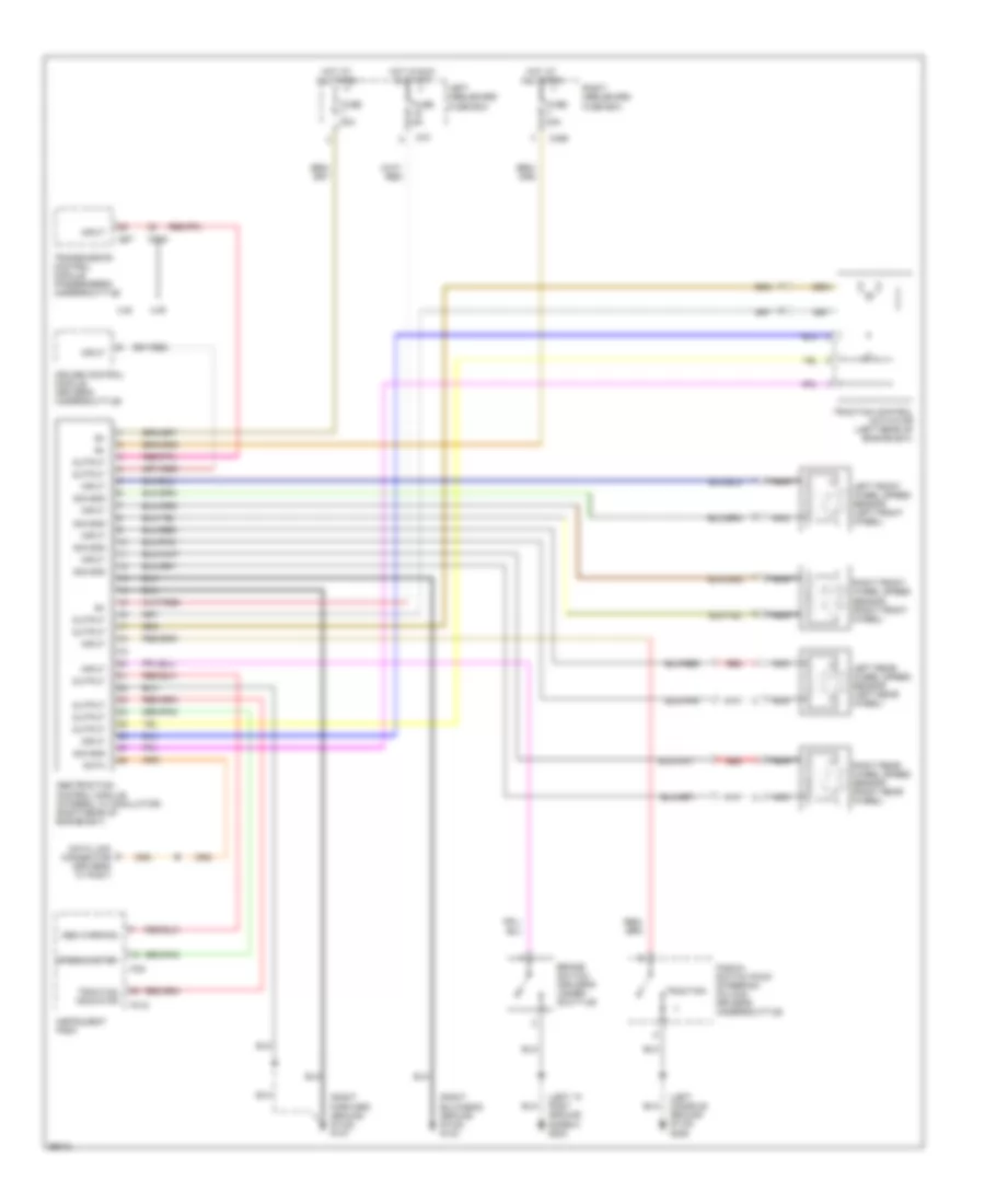
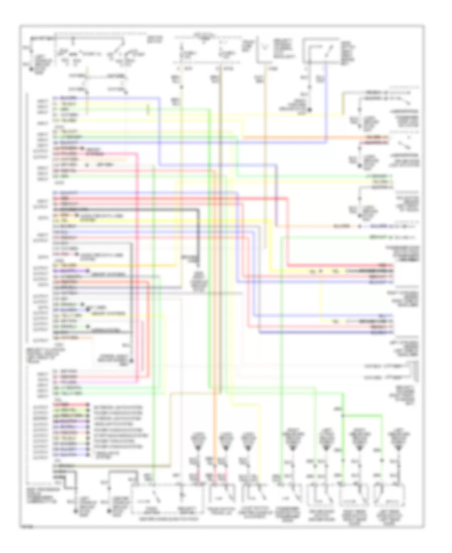
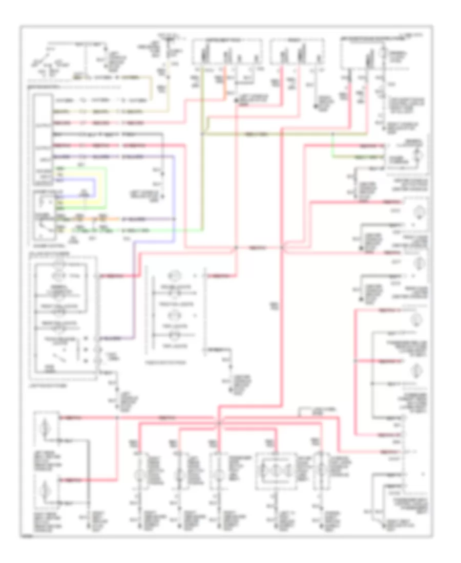
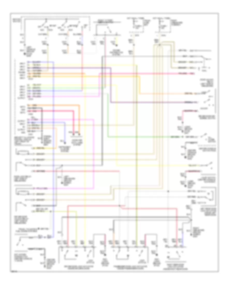
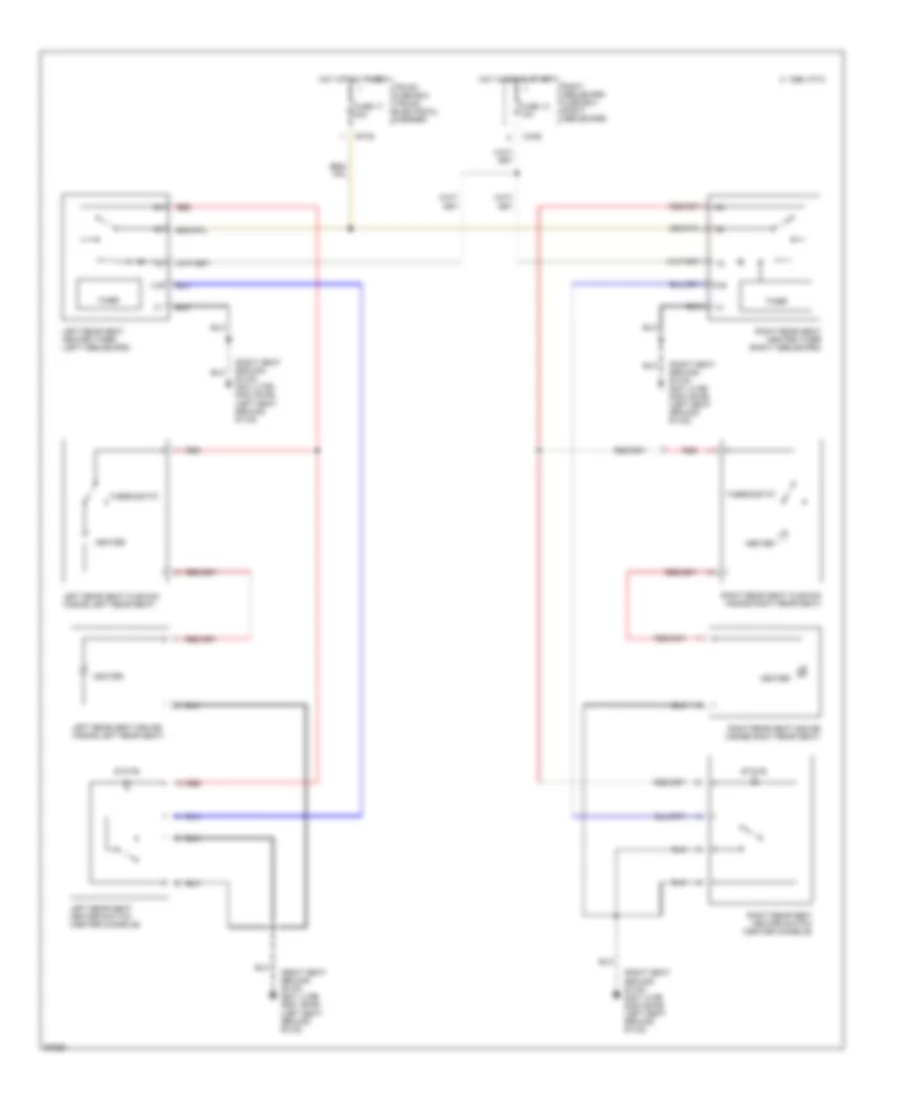
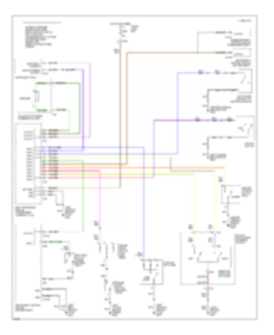
AIR CONDITIONING
Air Conditioning Wiring Diagrams (1 of 3) for Jaguar XJ6 L 1997
 https://portal-diagnostov.com/license.html
Automotive Electricians Portal FZCO
Automotive Electricians Portal FZCO
https://portal-diagnostov.com/license.html
https://portal-diagnostov.com/license.html
Automotive Electricians Portal FZCO
Automotive Electricians Portal FZCO
List of elements for Air Conditioning Wiring Diagrams (1 of 3) for Jaguar XJ6 L 1997:
- (left forward ground stud)
- (right rear of engine bay)
- Air conditioning clutch relay (right engine bay)
- Air conditioning compressor clutch
- Air conditioning control module (on center console)
- Cc28
- Cc29
- Door mirror heater relay
- Engine control module (right "a" post)
- Fan control relay module (front of engine bay)
- Fuse 10a
- Fuse 30a
- Fuse 5a
- G100
- G100 (left forward ground stud)
- Heated backlight relay
- Heated windshield relay
- Hot at all times
- Hot in run
- Instrument cluster
- Left air intake (in blower housing)
- Left engine bay fuse box
- Left radiator cooling fan
- Ls1
- Ls37
- Nca
- P1104
- P1105
- Pnk/red
- Pressure switch
- Radiator thermostatic switch (lower left of radiator)
- Refrigerant single pressure switch (right rear of engine bay)
- Refrigerant triple
- Right air intake (in blower housing)
- Right engine bay fuse box
- Right radiator cooling fan
- Rs1
- Rs6
- Supercharger intercooler coolant pump (xjr only)
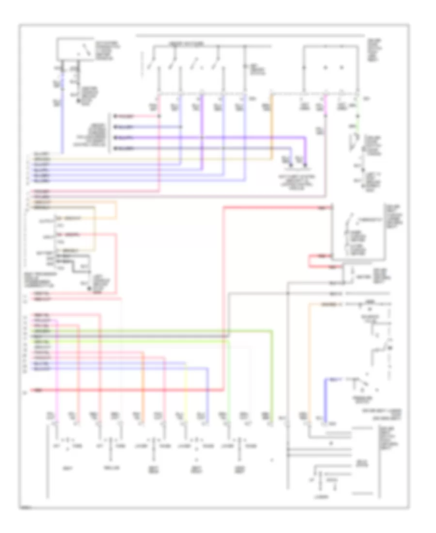
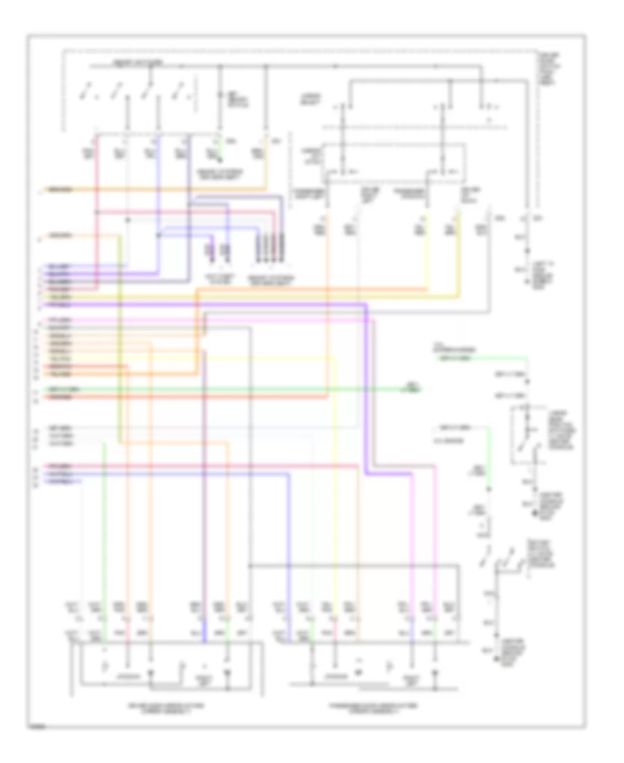
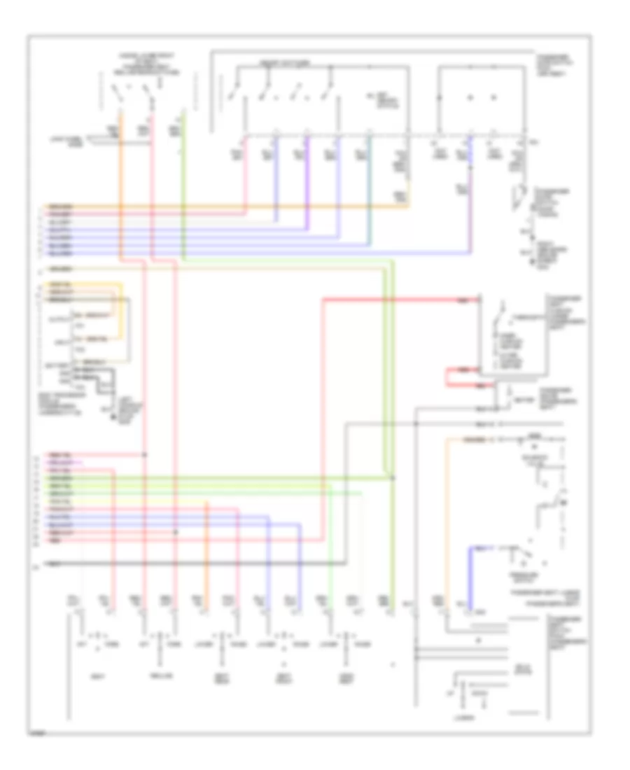
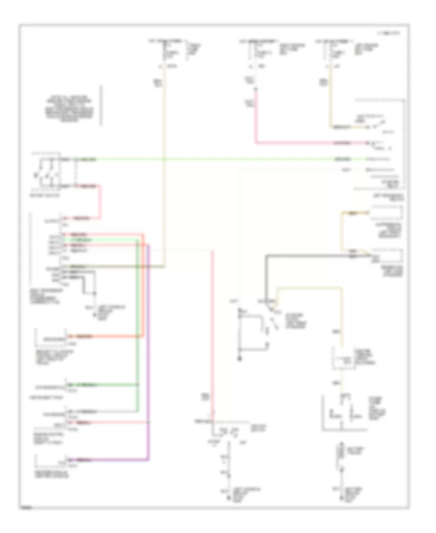
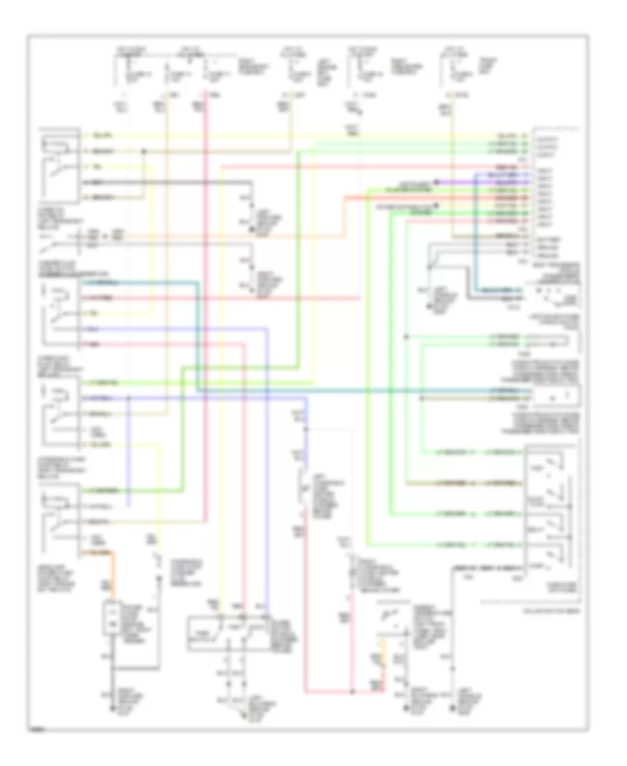
Air Conditioning Wiring Diagrams (2 of 3) for Jaguar XJ6 L 1997
List of elements for Air Conditioning Wiring Diagrams (2 of 3) for Jaguar XJ6 L 1997:
- (left bulkhead ground stud)
- (left kick panel) g200
- 1996-97
- Acc
- Ca2
- Ca36
- Ca44
- From vin
- Fuse 10a
- Fuse 15a
- Fuse 20a
- G116
- G116 (left bulkhead ground stud)
- G302 (left console ground stud)
- G302 (right console ground stud)
- Heater pump (left rear of engine bay)
- Heater pump relay (left side of engine bay)
- Heater valve (left rear of engine bay)
- Hot at all times
- Hot in run
- Ignition switch
- Inertia switch (right "a" post)
- Left blower motor (left side of i/p)
- Left blower motor relay (right kick panel)
- Left engine bay fuse box
- Left heelboard fuse box
- Left high speed relay (right kick panel)
- Lock
- Ls37
- Pnk/red
- Right blower motor (right side of i/p)
- Right blower motor relay (right kick panel)
- Right heelboard fuse box
- Right high speed relay (right kick panel)
- Run
- Start
- Up to vin
Air Conditioning Wiring Diagrams (3 of 3) for Jaguar XJ6 L 1997
List of elements for Air Conditioning Wiring Diagrams (3 of 3) for Jaguar XJ6 L 1997:
- (right "a" post)
- (right bulkhead stud)
- (right console ground stud)
- Acc
- Air conditioning control module (on center console)
- Air conditioning isolate relay (right kick panel)
- Ambient temperature sensor (left front wheel arch liner)
- Ca1
- Ca44
- Cc30
- Cc31
- Control panel
- Cool air bypass servo
- Data link connector (driver's "a" post)
- Defrost servo
- Differential control potentiometer (left side of a/c unit)
- Engine control
- Evapor- ator temp sensor
- Evaporator/heater matrix assembly (in a/c unit)
- Foot well servo
- Fuse 10a
- G201
- G203 (right kick panel)
- G302
- G302 (left console ground stud)
- G302 (right console ground stud)
- Heater matrix temp sensor
- Hot at all times
- Hot in run
- Ignition switch
- In-car temp sensor and aspir- ator assembly (left side of i/p)
- Instrument cluster
- Left heelboard fuse box
- Lock
- Logic ground stud
- Module
- P1104
- P1105
- Pnk
- Right heelboard fuse box
- Run
- Solar sensor (top of front fascia)
- Start
- Vent assembly (in a/c unit)
- Vent servo
- Xj6
- Xjr
ANTI-LOCK BRAKES
Anti-lock Brake Wiring Diagrams for Jaguar XJ6 L 1997
List of elements for Anti-lock Brake Wiring Diagrams for Jaguar XJ6 L 1997:
- (driver's "a" post)
- (left "a" post ground screw) g202
- (left console ground stud) g206
- (right bulkhead ground stud) g123
- (right forward ground stud) g107
- Abs warning
- Abs/traction control module (integral w/ modulator) (right rear of engine bay)
- Brake switch (driver's under- scuttle)
- Ca1
- Ca36
- Cc48
- Cc7
- Cruise control module (driver's underscuttle)
- Data
- Data link connector
- Fascia switch pack (steering column, driver's underscuttle)
- Fc10
- Fc9
- Fuse 30a
- Fuse 5a
- Hot at all times
- Hot in run & start
- Input
- Instrument pack
- Left front wheel speed sensor (left front wheel)
- Left heelboard fuse box
- Left rear wheel speed sensor (left rear wheel)
- Nca
- Output
- Red
- Right front wheel speed sensor (right front wheel)
- Right heelboard fuse box
- Right rear wheel speed sensor (right rear wheel)
- Sig gnd
- Speedometer
- Traction
- Traction control actuator (left rear of engine bay)
- Traction indicator
- Transmission control module (passenger's underscuttle)
- Xj6
- Xjr
ANTI-THEFT
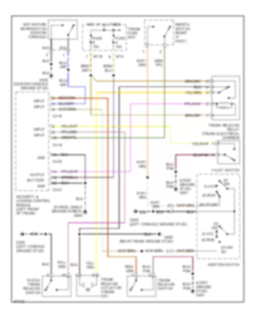
Anti-theft Wiring Diagram for Jaguar XJ6 L 1997
List of elements for Anti-theft Wiring Diagram for Jaguar XJ6 L 1997:
- (0) off
- (center console ground stud) g302
- (ii)
- (iii) start
- (left "a" post ground screw) g202
- (left console ground stud) g206
- (left heelboard ground screw) g304
- (logic ground stud) g401
- (not used)
- (parcel shelf ground screw) g904
- (right forward ground stud) g107
- (right heelboard ground screw) g303
- Acc (i)
- Body processor module (passenger's underscuttle)
- Braided wire
- Bt35
- Bt9
- Ca18
- Ca19
- Ca20
- Ca21
- Ca26
- Cc1
- Center console switch pack
- Computer data lines system
- Data
- Driver door lock actuator
- Driver door switch (driver door)
- Exterior lights system
- Fc1
- Fc2
- Fc3
- Fuse 4 10a
- Fuse 5 10a
- G206 (right console ground stud)
- Headlights system
- Hood switch (right front engine bay)
- Horns system
- Hot at all times
- Ignition switch
- Inclination sensor (left front of trunk)
- Input
- Interior lights system
- Left intrusion sensor (left side of headliner)
- Left rear door switch (left rear door)
- Lock status
- Memory systems
- Nca
- Off (0)
- Output
- Output output
- Panic switch
- Passenger door lock actuator
- Passenger door switch (passenger door)
- Passenger door switch pack (passenger's arm rest)
- Pnk
- Power tops system
- Power windows system
- Red
- Right intrusion sensor (right side of headliner)
- Right rear door switch (right rear door)
- Run (ii)
- Run acc (i)
- Security & locking control module (left front of trunk)
- Security active
- Security antenna (integral with backlight)
- Security sounder (right front of engine bay)
- Start (iii)
- Starting/charging system
- Trunk fuse box
- Trunk switch (trunk lid)
- Valet switch (center console glove box)
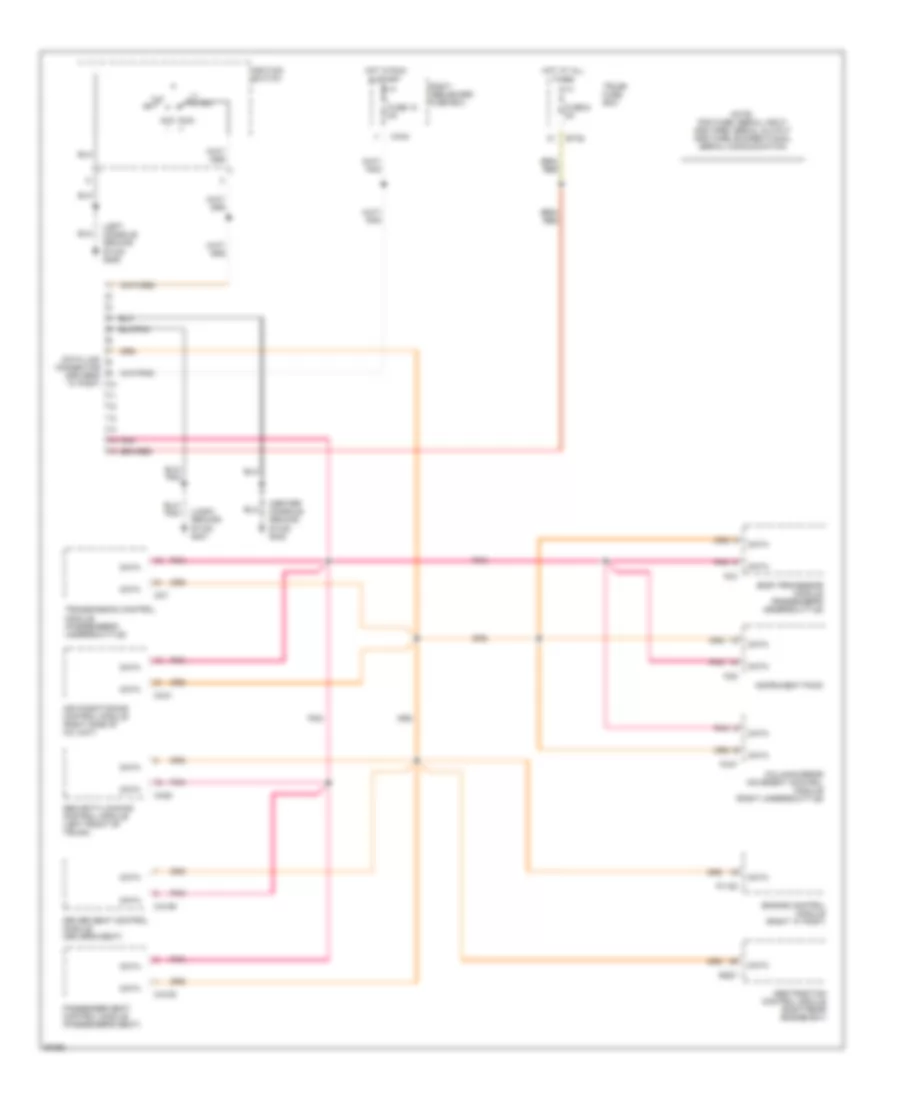
COMPUTER DATA LINES
Computer Data Lines for Jaguar XJ6 L 1997
List of elements for Computer Data Lines for Jaguar XJ6 L 1997:
- (center console ground stud) g302
- (left console ground stud) g206
- (logic ground stud) g401
- Abs/traction control module (right rear engine bay)
- Acc i
- Air conditioning control module (right side of a/c unit)
- Body processor module (passenger's underscuttle)
- Bt35
- Ca106
- Ca108
- Ca20
- Ca44
- Cc31
- Cc7
- Column/mirror movement control module (right underscuttle)
- Connector (driver's "a" post)
- Data
- Data link
- Driver seat control module (driver's seat)
- Engine control module (right "a" post)
- Fc3
- Fc47
- Fc9
- Fuse 10 5a
- Fuse 6 5a
- Hot at all times
- Hot in run & start
- Ignition switch
- Iii start
- Instrument pack
- Off
- P1105
- Passenger seat control module (passenger's seat)
- Pnk
- Right heelboard fuse box
- Rs27
- Run ii
- Security/locking control module (left front of trunk)
- Transmission control module (passenger's underscuttle)
- Trunk fuse box
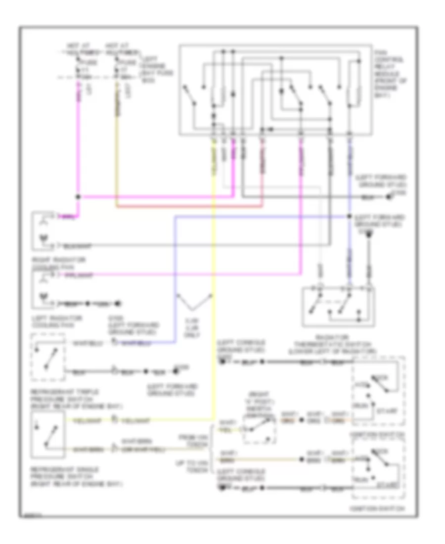
COOLING FAN
Cooling Fan Wiring Diagram for Jaguar XJ6 L 1997
List of elements for Cooling Fan Wiring Diagram for Jaguar XJ6 L 1997:
- (left console ground stud) g302
- (left forward ground stud)
- (right "a" post) inertia switch
- Acc
- Fan control relay module (front of engine bay)
- From vin
- Fuse 30a
- G100
- G100 (left forward ground stud)
- Hot at all times
- Ignition switch
- Left engine bay fuse box
- Left radiator cooling fan
- Lock
- Ls1
- Ls37
- Radiator thermostatic switch (lower left of radiator)
- Refrigerant single pressure switch (right rear of engine bay)
- Refrigerant triple pressure switch (right rear of engine bay)
- Right radiator cooling fan
- Run
- Start
- Up to vin
- Xj6/ xjr only
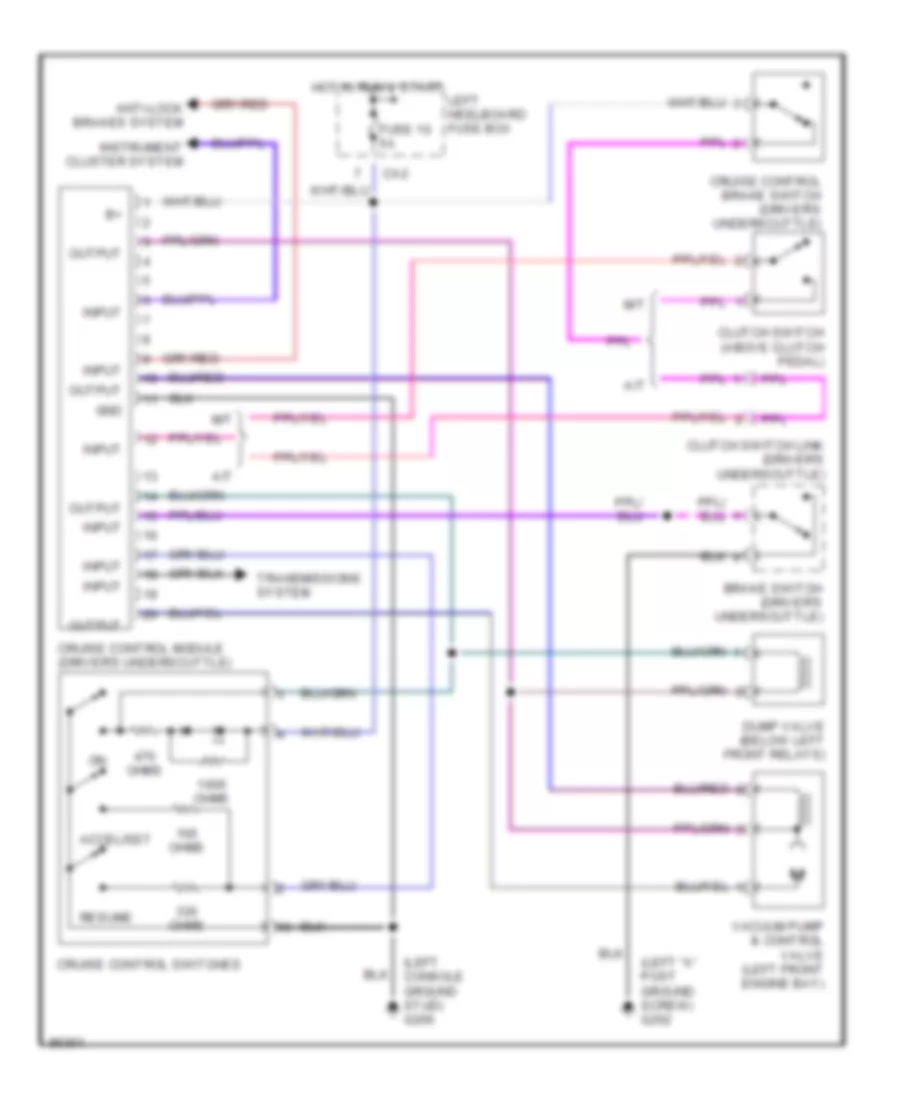
CRUISE CONTROL
Cruise Control Wiring Diagram for Jaguar XJ6 L 1997
List of elements for Cruise Control Wiring Diagram for Jaguar XJ6 L 1997:
- (left "a" post ground screw) g202
- (left console ground stud) g206
- A/t
- Accel/set
- Anti-lock brakes system
- Brake switch (driver's underscuttle)
- Ca2
- Clutch switch (above clutch pedal)
- Clutch switch link (driver's underscuttle)
- Cruise control brake switch (driver's underscuttle)
- Cruise control module (driver's underscuttle)
- Cruise control switches
- Dump valve (below left front relays)
- Fuse 10 5a
- Gnd
- Hot in run & start
- Input
- Instrument cluster system
- Left heelboard fuse box
- M/t
- Ohms
- Output
- Resume
- Transmissions system
- Vacuum pump & control valve (left front engine bay)
DEFOGGERS
Defogger Wiring Diagram for Jaguar XJ6 L 1997
List of elements for Defogger Wiring Diagram for Jaguar XJ6 L 1997:
- (left "a" post ground screw) g202
- (left bulkhead ground stud) g116
- (parcel shelf ground screw) g904
- (right heelboard ground screw) g303
- Air conditioning control module (right side of a/c unit)
- Bt35
- Ca1
- Ca2
- Ca36
- Ca4
- Ca44
- Cc28
- Cc31
- Door mirror heater relay (right heelboard)
- Driver's mirror
- Fuse 10a
- Fuse 25a
- Heated backlight
- Heated backlight relay (trunk electrical carrier)
- Hot at all times
- Hot in run & start
- Left engine bay fuse box
- Left heelboard fuse box
- Left windshield heater
- Left windshield heater relay (left "a" post)
- Ls1
- Ls37
- Output
- Passenger's mirror
- Right heelboard fuse box
- Right windshield heater
- Right windshield heater relay (left "a" post)
- Trunk fuse box
ELECTRONIC POWER STEERING
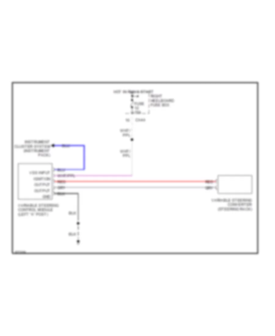
Electronic Power Steering Wiring Diagram for Jaguar XJ6 L 1997
List of elements for Electronic Power Steering Wiring Diagram for Jaguar XJ6 L 1997:
- Ca44
- Fuse 10a
- Gnd
- Hot in run & start
- Ignition
- Instrument cluster system (instrument pack)
- Output
- Red
- Right heelboard fuse box
- Variable steering control module (left "a" post)
- Variable steering converter (steering rack)
- Vss input
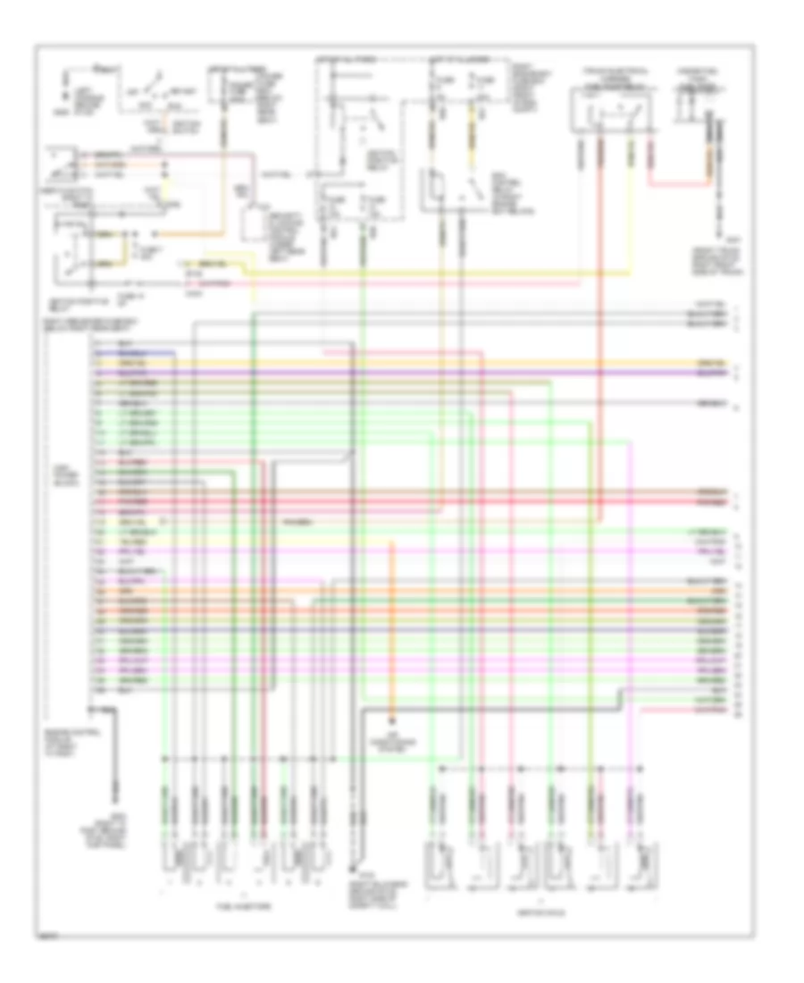
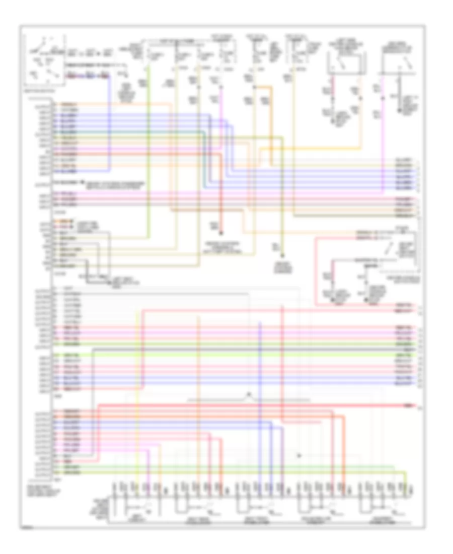
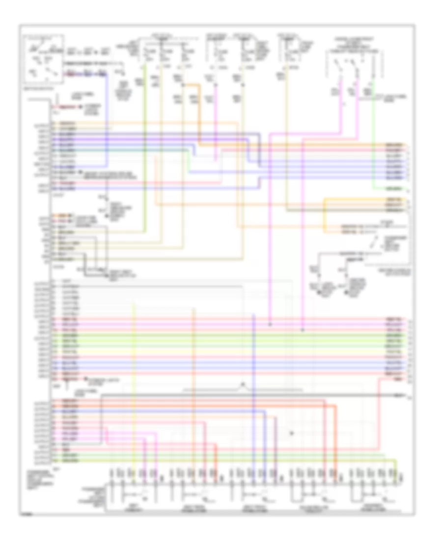
ENGINE PERFORMANCE
4.0L
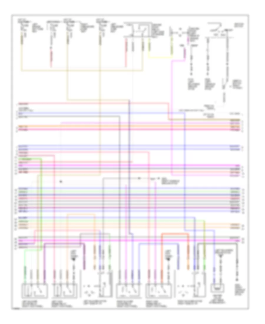
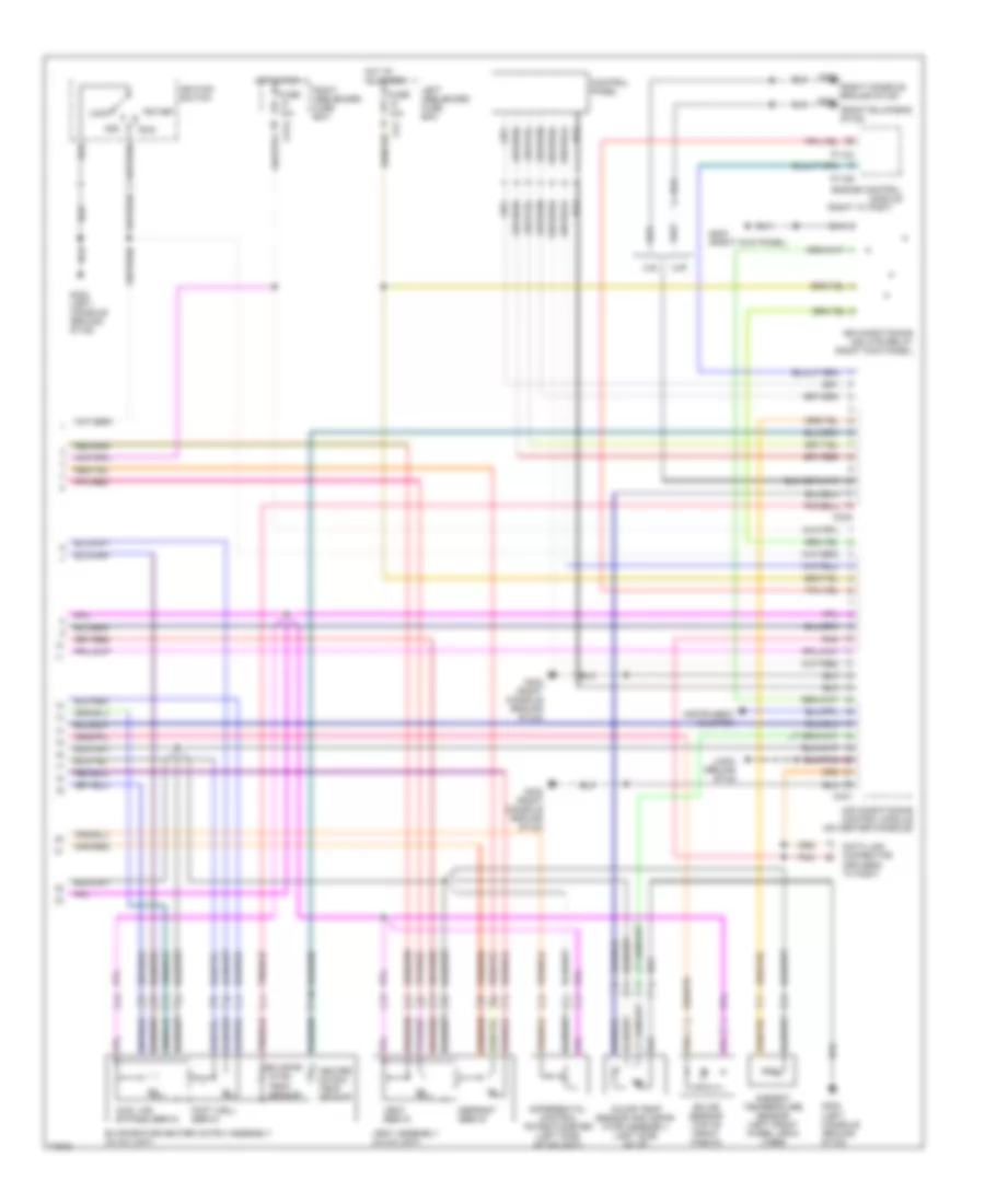
4.0L, Engine Performance Wiring Diagrams (1 of 3) for Jaguar XJ6 L 1997
List of elements for 4.0L, Engine Performance Wiring Diagrams (1 of 3) for Jaguar XJ6 L 1997:
- (front trunk ground stud, right front side of trunk)
- (inside fuel tank) fuel pump
- (left console ground stud)
- (right bulkhead ground stud, right side of safety wall)
- (trunk electrical carrier) fuel pump relay
- 20a
- Acc
- Air conditioning system
- Bt35
- C10
- Ca2
- Ca44
- Ecm control relay (in right engine bay relays)
- Engine control module (at right "a" post)
- Fuel injectors
- Fuse
- Fuse 10 5a
- Fuse 10a
- Fuse 7 30a
- G123
- G203 (right "a" post ground stud, right kick panel)
- G206
- G401
- High power (black)
- Hot at all times
- Ignition coils
- Ignition positive relay
- Ignition switch
- Inertia switch (right "a" post)
- Nca
- Off
- Pnk/red
- Power fuse 250a
- Power fuse box (below right rear seat)
- Right engine bay fuse box (right front of eng compt)
- Right heelboard fuse box (below right rear seat)
- Rs1
- Rs6
- Run
- Security & locking control module (under left rear seat)
- Start
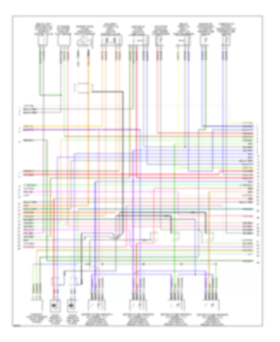
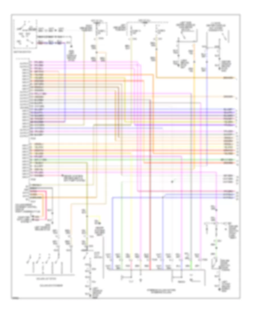
4.0L, Engine Performance Wiring Diagrams (2 of 3) for Jaguar XJ6 L 1997
List of elements for 4.0L, Engine Performance Wiring Diagrams (2 of 3) for Jaguar XJ6 L 1997:
- (adjacent to throttle body) idle air control valve
- (at engine air intake) mass air flow sensor
- (below left front relays) evaporative emission control valve
- (below throttle body) throttle position sensor
- (center of intake manifold) egr valve
- (engine air intake elbow) intake air temperature sensor
- (engine timing cover) crankshaft position sensor
- (on intake manifold) egr temper- ature sensor
- (thermostat housing) engine coolant temperature sensor
- Camshaft position sensor (right side of eng)
- Heated oxygen sensor a (cylinders 1, 2, 3 downstream) (downstream of primary catalyst)
- Heated oxygen sensor a (cylinders 1, 2, 3 upstream) (upstream of primary catalyst)
- Heated oxygen sensor b (cylinders 4, 5, 6 downstream) (downstream of primary catalyst)
- Heated oxygen sensor b (cylinders 4, 5, 6 upstream) (upstream of primary catalyst)
- Knock sensor a (left front of eng)
- Knock sensor b (left rear of eng)
- Nca
- Pnk/red
- Red
- Red/pnk
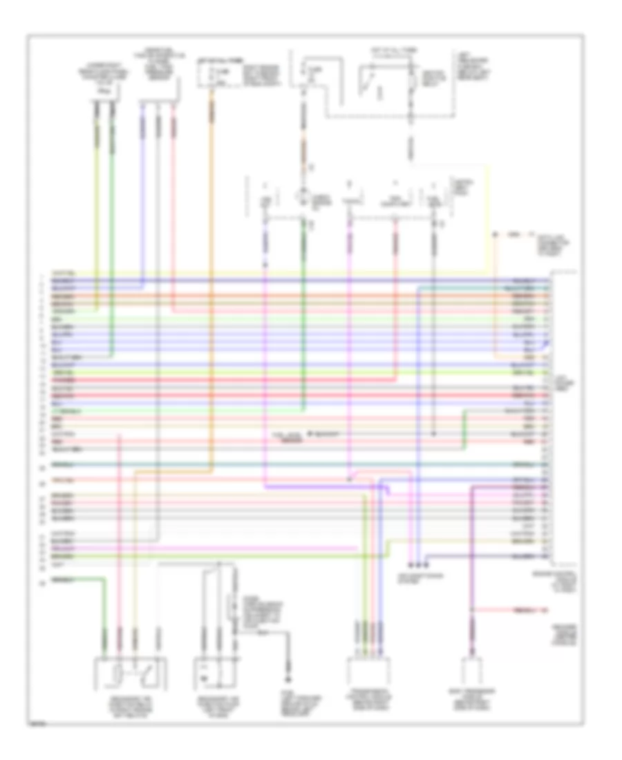
4.0L, Engine Performance Wiring Diagrams (3 of 3) for Jaguar XJ6 L 1997
List of elements for 4.0L, Engine Performance Wiring Diagrams (3 of 3) for Jaguar XJ6 L 1997:
- (near fuel tank evaporative flange) fuel tank pressure sensor
- (under right rear floor panel) canister close valve
- Air conditioning system
- Body processor module (behind right side of dash)
- C10
- Check engine mil
- Computer
- Data link connector (driver's "a" post)
- Decoder module (center console)
- Diode (airp solenoid suppression) (adjacent to air injection pump)
- Engine control module (at right "a" post)
- Fuel level
- Fuel level sensor
- Fuse 25a
- Fuse 5a
- G106 (left forward ground stud, behind left headlamp)
- Hot at all times
- Ignition positive relay
- Instru- ment pack
- Left heelboard fuse box (below left rear seat)
- Low power (red)
- Nca
- Pnk/red
- Red
- Red/pnk
- Right engine bay fuse box (right front of eng compt)
- Secondary air injection pump (left front of eng)
- Secondary air injection relay (in right engine bay relays)
- Tacho
- Transmission control module (behind right side of dash)
- Trip
- Vss out
EXTERIOR LIGHTS
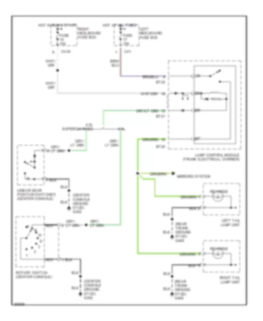
Back-up Lamps Wiring Diagram for Jaguar XJ6 L 1997
List of elements for Back-up Lamps Wiring Diagram for Jaguar XJ6 L 1997:
- (center console ground stud) g302
- (rear trunk ground stud) g405
- 4.0l
- 4.0l supercharged
- Bt20
- Bt21
- Ca1
- Ca36
- Fuse 10a
- Hot at all times
- Hot in run & start
- Lamp control module (trunk electrical carrier)
- Left heelboard fuse box
- Left tail lamp unit
- Linear gear position switches (center console)
- Mirrors system
- Nca
- Reverse
- Right heelboard fuse box
- Right tail lamp unit
- Rotary switch (center console)
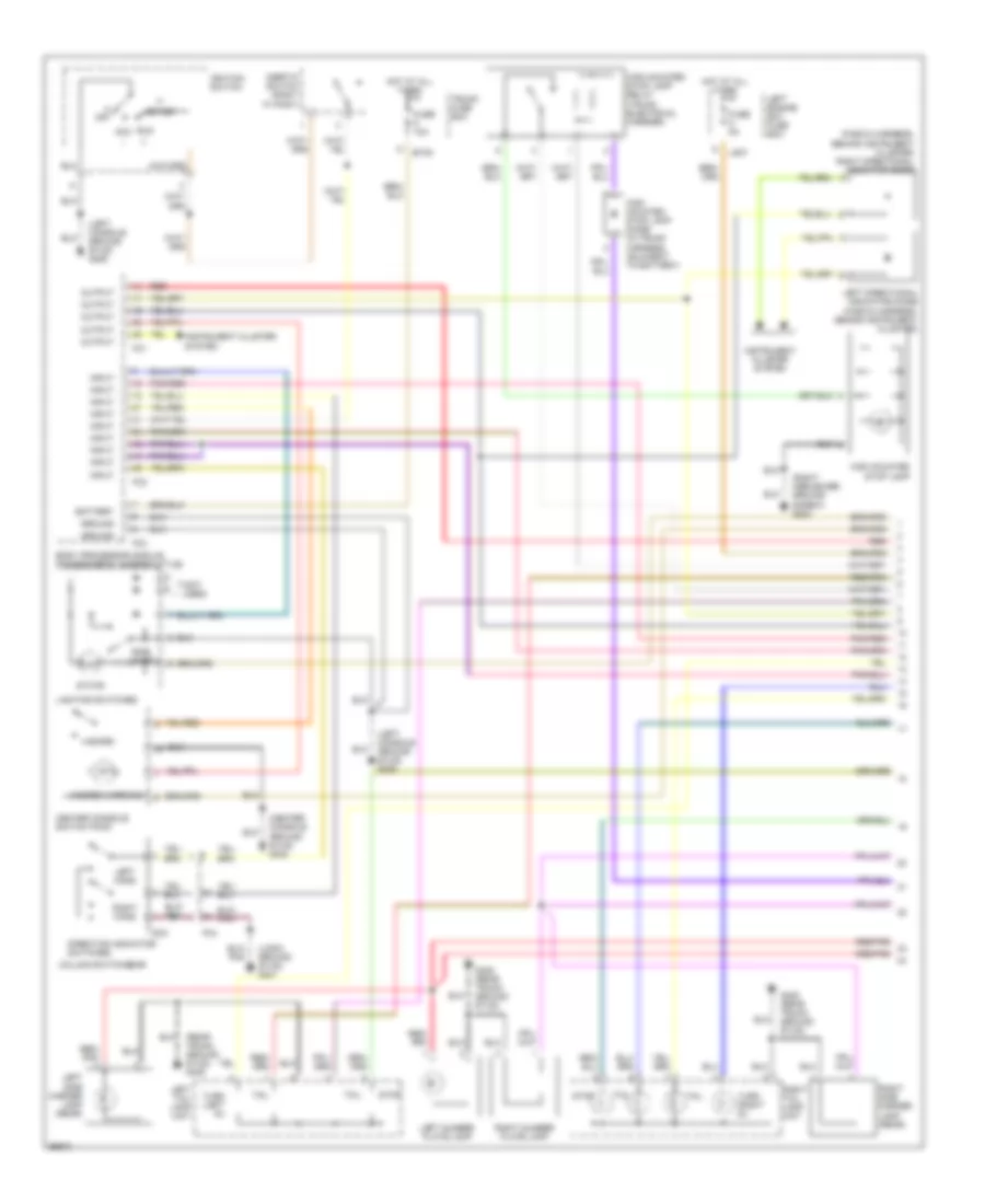
Exterior Lamps Wiring Diagram (1 of 2) for Jaguar XJ6 L 1997
List of elements for Exterior Lamps Wiring Diagram (1 of 2) for Jaguar XJ6 L 1997:
- (center console ground stud) g302
- (fascia harness, behind instrument cluster) right directional indicator diode
- (left console ground stud) g206
- (logic ground stud) g401
- (not used)
- (rear trunk ground stud) g405
- (right heelboard ground screw) g303
- Acc
- Battery
- Body processor module (passenger's underscuttle)
- Bt35
- Center console switch pack
- Column switchgear
- Direction indicator switches
- Fc1
- Fc2
- Fc3
- Fc4
- Fuse 10a
- Fuse 5a
- G405 (rear trunk ground stud)
- Ground
- Hazard
- Hazard warning
- High mounted stop lamp
- High mounted stop lamp diode (in trunk harness, adjacent to battery)
- High mounted stop lamp relay (trunk electrical carrier)
- Hot at all times
- Ignition switch
- Iii
- Inertia switch (right "a" post)
- Input
- Instrument cluster system
- Left directional indicator diode (fascia harness, behind instrument cluster)
- Left engine bay fuse box
- Left hand
- Left number plate lamp
- Left side marker lamp (rear)
- Left tail lamp unit
- Lighting switches
- Ls37
- Off
- Output
- Pnk/red
- Red
- Red/ pnk
- Red/pnk red/pnk
- Right hand
- Right number plate lamp
- Right side marker lamp (rear)
- Right tail lamp unit
- Run
- Sc3
- Side lamps
- Start
- State
- Stop
- Tail
- Trunk fuse box
- Turn (left di)
- Turn (right di)
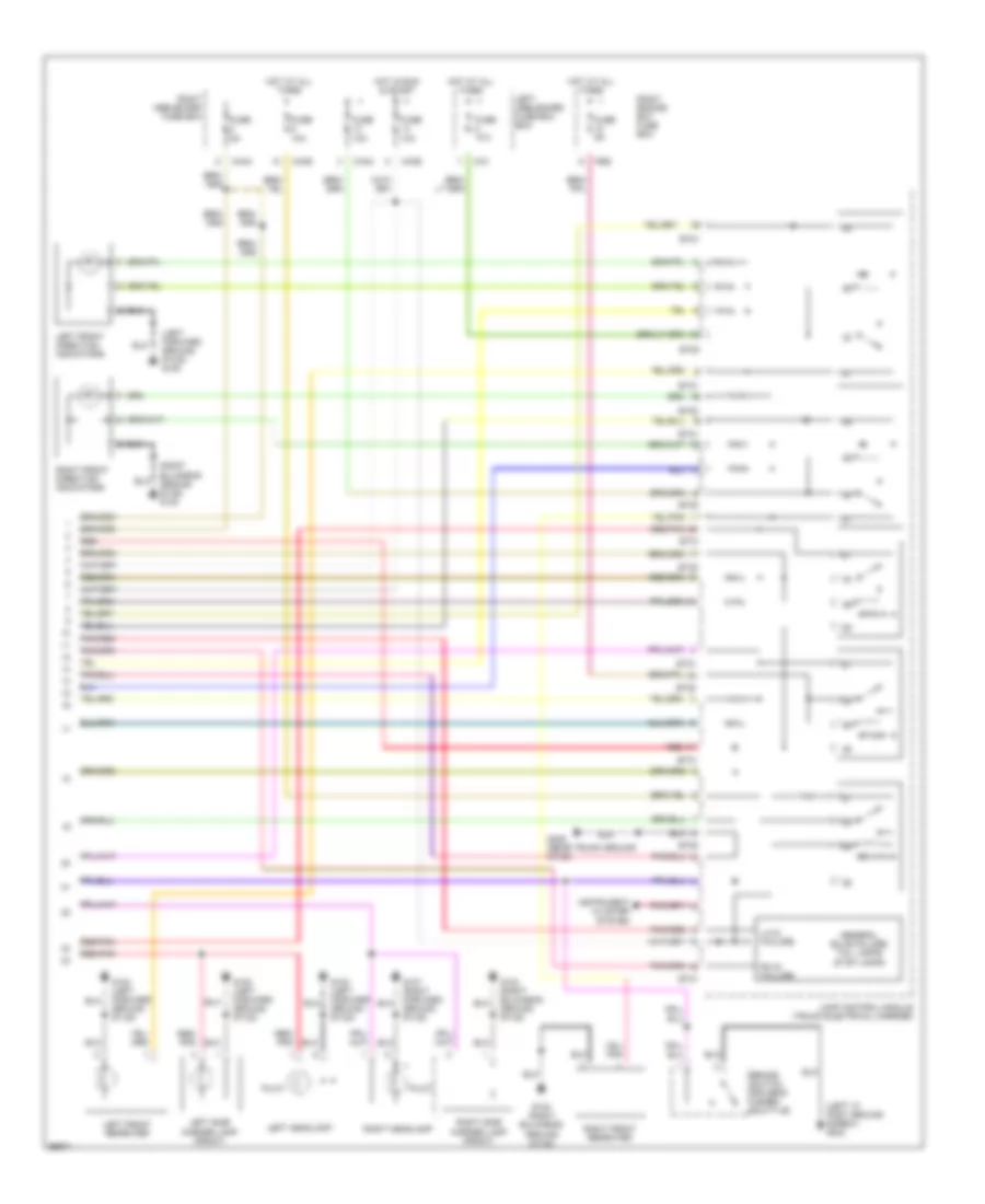
Exterior Lamps Wiring Diagram (2 of 2) for Jaguar XJ6 L 1997
List of elements for Exterior Lamps Wiring Diagram (2 of 2) for Jaguar XJ6 L 1997:
- (left "a" post ground screw) g202
- (left forward ground stud) g100
- (right bulkhead ground stud) g123
- Brake switch driver's under- scuttle)
- Bt20
- Bt21
- Ca1
- Ca36
- Ca44
- Fuse 10a
- Fuse 5a
- G100 (left forward ground stud)
- G107 (right forward ground stud)
- G123 (right bulkhead ground stud)
- G405 (rear trunk ground stud)
- General bulb failure: tail lamps stop lamps
- Hot at all times
- Hot in run & start
- Instrument cluster system
- Lamp control module (trunk electrical carrier)
- Left front direction indicators
- Left front repeater
- Left headlamp
- Left heelboard fuse box box
- Left side marker lamp (front)
- Lh di failure
- Pilot
- Pnk/red
- Red
- Red/ pnk
- Red/pnk
- Rh di failure
- Right engine bay fuse box
- Right front direction indicators
- Right front repeater
- Right headlamp
- Right heelboard fuse box
- Right side marker lamp (front)
- Rs6
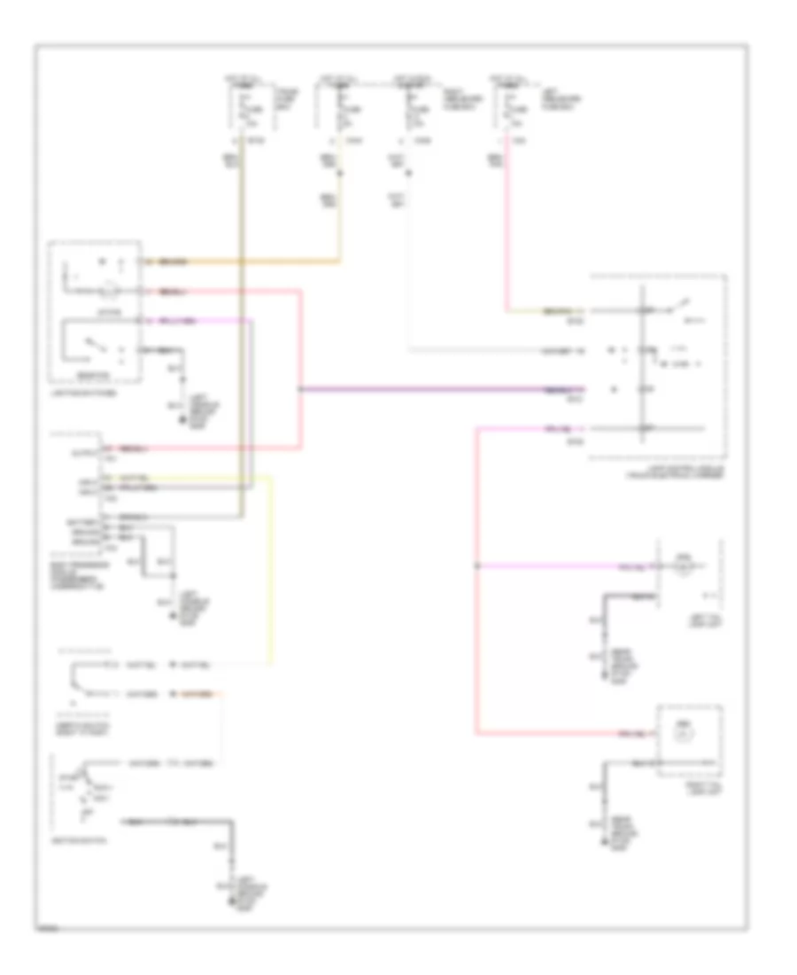
Rear Fog Lamps Wiring Diagram for Jaguar XJ6 L 1997
List of elements for Rear Fog Lamps Wiring Diagram for Jaguar XJ6 L 1997:
- (left console ground stud) g206
- (rear trunk ground stud) g405
- Acc i
- Battery
- Body processor module (passenger's underscuttle)
- Bt20
- Bt21
- Bt35
- Ca2
- Ca36
- Ca44
- Fc1
- Fc2
- Fc3
- Fog
- Fuse 10a
- Fuse 5a
- Ground
- Hot at all times
- Hot in run & start
- Ignition switch
- Iii start
- Inertia switch (right "a" post)
- Input
- Lamp control module (trunk electrical carrier)
- Left heelboard fuse box
- Left tail lamp unit
- Lighting switches
- Off
- Output
- Rear fog
- Right heelboard fuse box
- Right tail lamp unit
- Run ii
- State
- Trunk fuse box
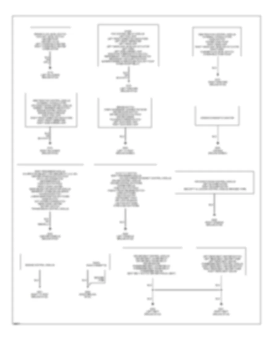
GROUND DISTRIBUTION
Ground Distribution Wiring Diagram (1 of 2) for Jaguar XJ6 L 1997
List of elements for Ground Distribution Wiring Diagram (1 of 2) for Jaguar XJ6 L 1997:
- Abs/traction control module (integral w/modulator) air conditioning control module ambient temperature switch engine control module engine shield ground right fog lamp right front direction indicators right front repeater right side marker lamp
- Abs/traction control module (integral w/modulator) hood switch power wash pump right headlamp right headlamp leveling actuator right horn washer fluid level switch windshield wash pump
- Air bag diagnostic monitor
- Air conditioning control module left blower motor right blower motor security & locking control module (braided wire)
- Auto tilt switch body processor module
- Body processor module calibration select link (dealer fit) (4.0l sc) center console switch pack data link connector decoder module fascia switch pack front cigar lighter gear selector indicator module gearshift interlock solenoid kickdown switch linear gear position switches mode switch not in-park microswitch rear cigar lighter rotary switch transmission control module
- Braided wire
- Brake fluid level switch coolant level switch heater pump heater valve left windshield heater right windshield heater wiper motor
- Brake switch cabin accessory connector (swb) driver door switch driver door switch pack driver mirror fold-back mirror switch left sunvisor lamp right sunvisor lamp
- Column mirror movement control module
- Cruise control module cruise control switches dimmer module fascia switch pack fascia trunk release switch horn switches ignition switch instrument pack keylock solenoid lighting switches wipe/wash switches
- Diode fan control relay module left fog lamp left front direction indicators left front repeater left headlamp left headlamp leveling actuator left horn left side marker lamp radiator thermostatic switch refrigerant triple pressure switch secondary air injection pump supercharger intercooler coolant pump wiper on/off relay
- Driver seat control module driver seat lower relay driver seat raise relay driver squab passenger seat lower relay passenger seat raise relay passenger squab seat belt switch (driver manual seat)
- Engine control module
- G100 (left forward ground stud)
- G107 (right forward ground stud)
- G116 (left bulkhead ground stud)
- G123 (right bulkhead ground stud)
- G201 (right "a" post ground stud)
- G202 (air bag ground screw)
- G202 (left "a" post ground screw)
- G206 (left console ground stud)
- G206 (radio ground stud)
- G206 (right console ground stud)
- G300 (left seat ground stud)
- G301 (right seat ground stud)
- G302 (center console ground stud)
- Left rear seat heater switch left rear seat heater timer left rear seat squab passenger seat control module right rear seat heater switch right rear seat heater timer right rear seat squab
- Radio radio cassette
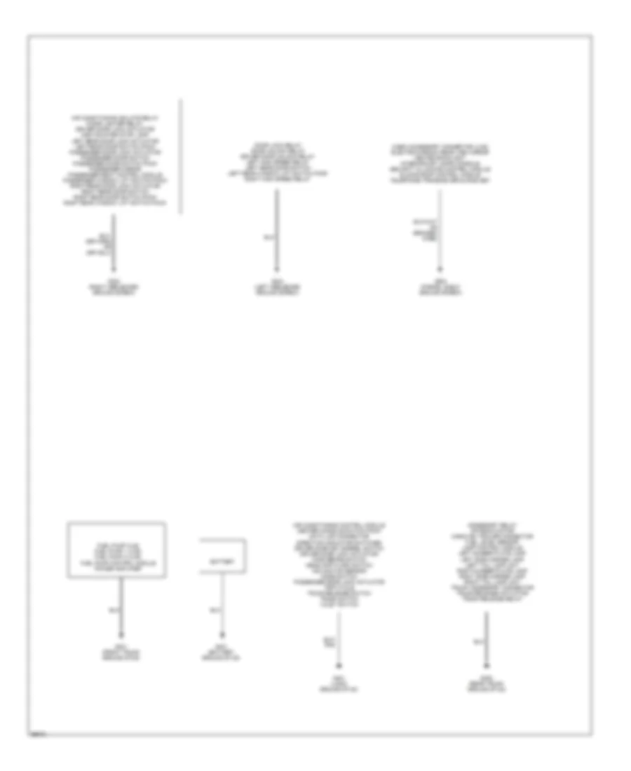
Ground Distribution Wiring Diagram (2 of 2) for Jaguar XJ6 L 1997
List of elements for Ground Distribution Wiring Diagram (2 of 2) for Jaguar XJ6 L 1997:
- Accessory relay antenna motor caravan/ trailer connector fuel level sensor lamp control module left number plate lamp left side marker lamp left tail lamp unit right number plate lamp right side marker lamp right tail lamp unit trunk accessory connector trunk release actuator trunk release relay
- Air conditioning control module center console switch pack data link connector direction indicator switches driver door key barrel switch driver door lock actuator hand brake switch headlamp flash switch inclination sensor mode switch passenger door lock actuator trip cycle trunk release switch trunk switch valet switch
- Air conditioning isolate relay cigar lighter relay driver door lock actuator high mounted stop lamp left rear door lock actuator left rear door switch pack passenger door lock actuator passenger door switch passenger door switch pack passenger mirror passenger seat control module passenger window lift switch pack right rear door lock actuator right rear door switch right rear door switch pack right rear window lift switch pack
- Battery
- Cabin accessory connector (lws) electro-chromic rear view mirror heated backlight interior/map lamps console security & locking control module sliding roof control module telephone transceiver & hand set
- Door lock relay door unlock relay driver door unlock relay left high speed relay left rear door switch left rear window lift switch pack right high speed relay
- Fuel pump (xj6) fuel pump 1 (xjr) fuel pump 2 (xjr) fuel pump control module power amplifier
- G303 (right heelboard ground screw)
- G304 (left heelboard ground screw)
- G401 (battery ground stud)
- G401 (front trunk ground stud)
- G401 (logic ground stud)
- G405 (rear trunk ground stud)
- G904 (parcel shelf ground screw)
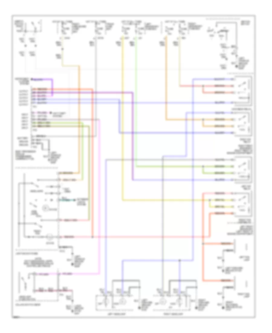
HEADLIGHTS
Headlamps Wiring Diagram for Jaguar XJ6 L 1997
List of elements for Headlamps Wiring Diagram for Jaguar XJ6 L 1997:
- (left console ground stud) g206
- (left forward ground stud) g100
- (logic ground stud) g401
- (not used)
- (right bulkhead ground stud) g123
- (right forward ground stud) g107
- Acc
- Anti-theft system
- Battery
- Body processor module (passenger's underscuttle)
- Bt35
- Ca44
- Column switch gear
- Dip
- Exterior lights system
- Fc1
- Fc12
- Fc2
- Fc3
- Fc4
- Front fog
- Front fog lamp relay
- Fuse 10a
- Fuse 15a
- Fuse 5a
- Ground
- Headlamp flash switch
- Headlamps
- Hot at all times
- Ignition switch
- Iii
- Inertia switch (right "a" post)
- Input
- Instrument cluster system
- Left dip relay
- Left engine bay fuse box
- Left fog lamp
- Left front engine bay (left front of engine compartment)
- Left headlamp
- Lighting switches
- Ls1
- Ls37
- Main
- Main beam relay
- Note: daytime running lamps- body processor module controlled (pecus)
- Off
- Output
- Right dip relay
- Right engine bay fuse box
- Right fog lamp
- Right front engine bay (right front of engine compartment)
- Right headlamp
- Right heelboard fuse box
- Rs1
- Run
- Side lamps
- Start
- State
- Trunk fuse box
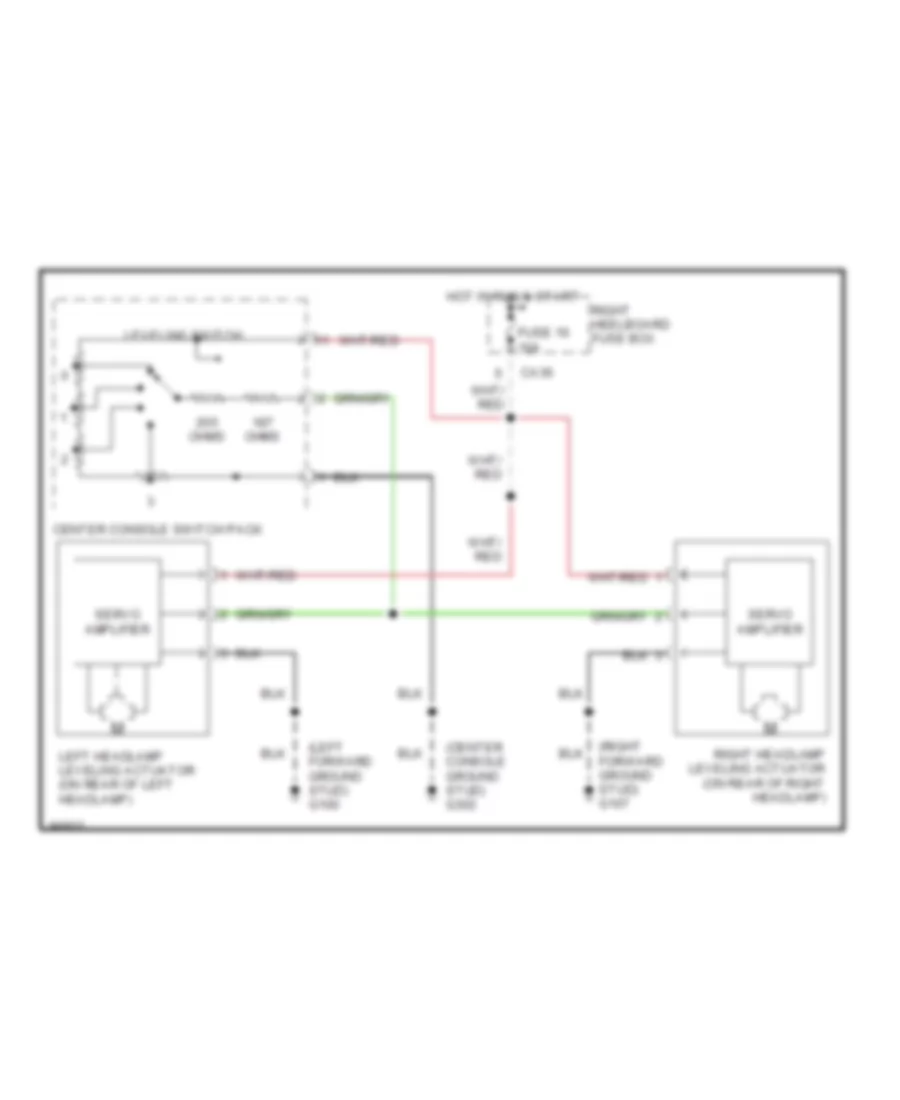
Headlamps Leveling Wiring Diagram for Jaguar XJ6 L 1997
List of elements for Headlamps Leveling Wiring Diagram for Jaguar XJ6 L 1997:
- (center console ground stud) g302
- (left forward ground stud) g100
- (right forward ground stud) g107
- Ca36
- Center console switch pack
- Fuse 16 10a
- Hot in run & start
- Left headlamp leveling actuator (on rear of left headlamp)
- Leveling switch
- Ohms
- Right headlamp leveling actuator (on rear of right headlamp)
- Right heelboard fuse box
- Servo amplifier
HORN
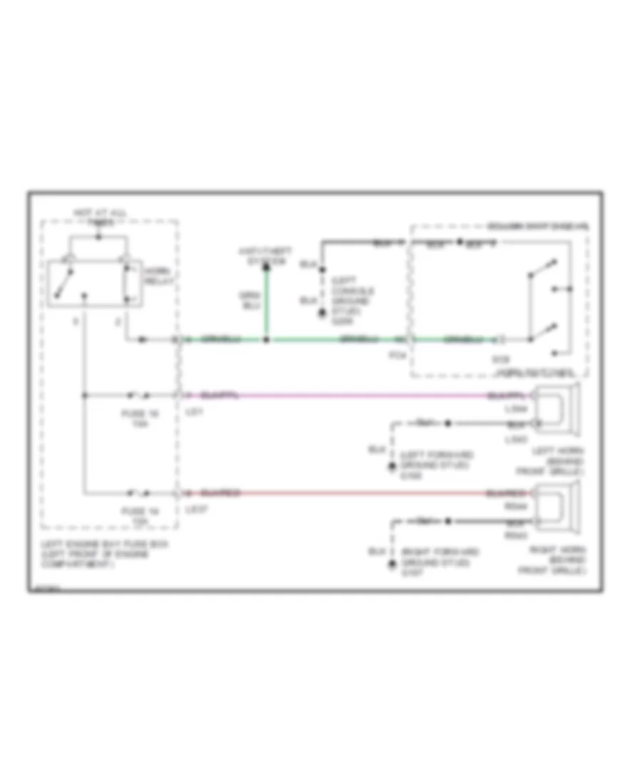
Horn Wiring Diagram for Jaguar XJ6 L 1997
List of elements for Horn Wiring Diagram for Jaguar XJ6 L 1997:
- (left console ground stud) g206
- (left forward ground stud) g100
- (right forward ground stud) g107
- Anti-theft system
- Column switchgear
- Fc4
- Fuse 10 10a
- Fuse 14 10a
- Horn relay
- Horn switches
- Hot at all times
- Left engine bay fuse box (left front of engine compartment)
- Left horn (behind front grille)
- Ls1
- Ls37
- Ls43
- Ls44
- Right horn (behind front grille)
- Rs43
- Rs44
- Sc9
INSTRUMENT CLUSTER
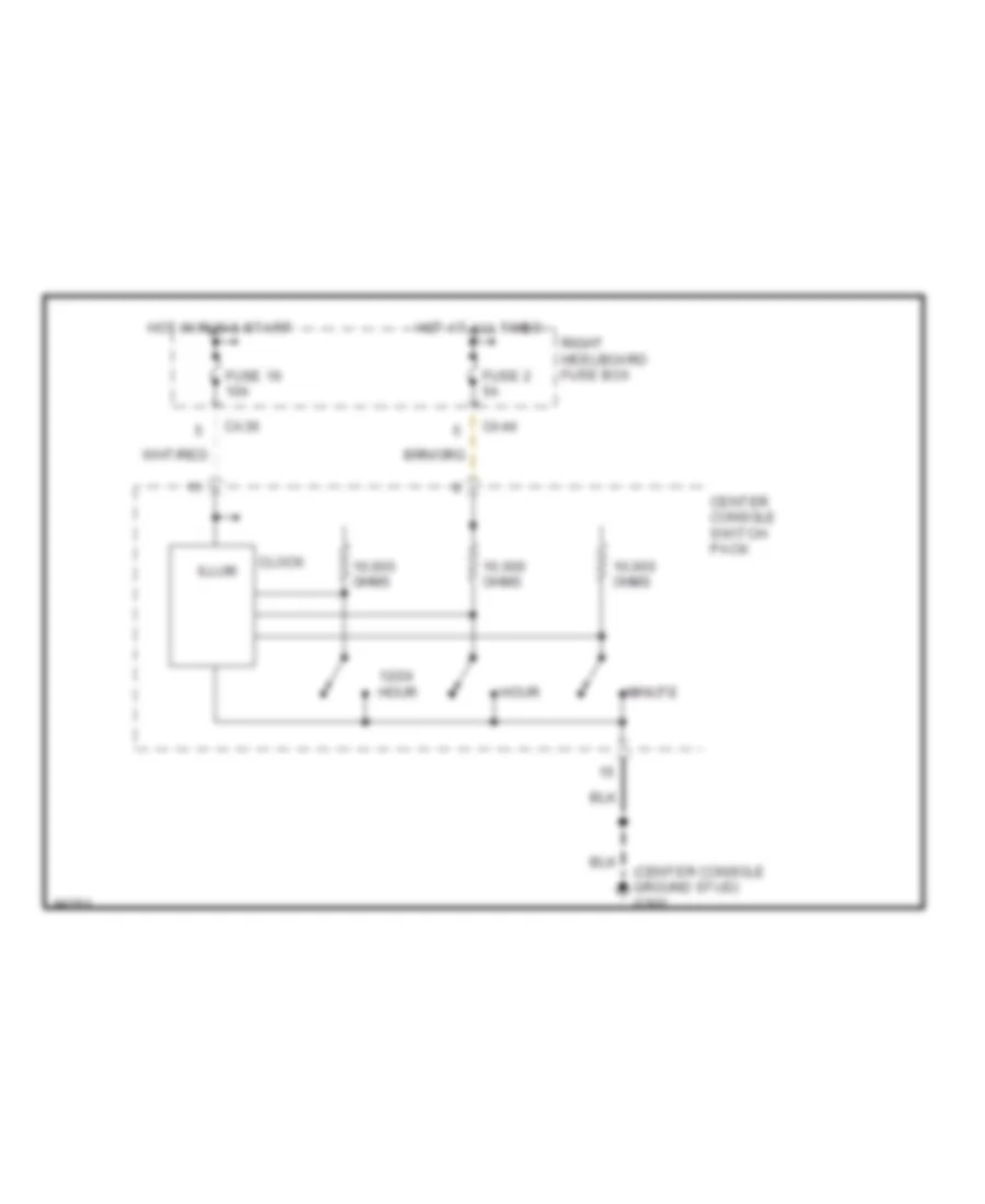
Clock Wiring Diagram for Jaguar XJ6 L 1997
List of elements for Clock Wiring Diagram for Jaguar XJ6 L 1997:
- (center console ground stud) g302
- 10,000 ohms
- 12/24 hour
- Ca36
- Ca44
- Center console switch pack
- Clock
- Fuse 16 10a
- Fuse 2 5a
- Hot at all times
- Hot in run & start
- Hour
- Illum
- Minute
- Right heelboard fuse box
Instrument Cluster Wiring Diagram for Jaguar XJ6 L 1997
List of elements for Instrument Cluster Wiring Diagram for Jaguar XJ6 L 1997:
- (left bulkhead ground stud) g116
- (left console ground stud) g206
- (left seat ground stud) g300
- (logic ground stud) g401
- (rear trunk ground stud) g405
- (right forward ground stud) g107
- 21d
- Abs warning input
- Air bag warning input
- Air conditioning system
- Anti-lock brakes system
- Battery
- Body processor module (passenger's underscuttle)
- Brake fluid level switch (brake fluid reservoir)
- Brake fluid level warn in
- Bt35
- Ca1
- Ca105
- Ca106
- Ca2
- Charge indicator input
- Check engine mil input
- Clear
- Column switchgear
- Computer data lines system
- Coolant level switch (coolant reservoir)
- Coolant level warning in
- Coolant temp input
- Coolant temp output
- Coolant temperature sensor (engine thermostat housing)
- Cruise control system
- Data
- Directional bulb failure
- Door locks system
- Driver door open warning
- Driver seat control module (under driver's seat)
- Electronic power steering system
- Engine controls system
- Except manual seat
- Exterior lights system
- Fascia switch pack
- Fc1
- Fc10
- Fc2
- Fc3
- Fc9
- Fuel level input
- Fuel level sensor (fuel tank)
- Fuse 12 5a
- Fuse 16 5a
- Fuse 5 10a
- G300 (left seat ground stud)
- G401 (logic ground stud)
- General bulb failure input
- Ground
- Hand brake switch (left side center console)
- Headlights system
- Hot at all times
- Hot in acc & run
- Hot in run & start
- Ignition
- Input
- Instrument pack
- Interior lights system
- Left directional ind
- Left heelboard fuse box
- Main beam indicator input
- Manual seat
- Memory systems
- Mph/ kph
- Ohms
- Oil pressure input
- Oil pressure switch (left side of engine block)
- Output
- Park brake input
- Passenger door open
- Pnk
- Pnk/red
- Red
- Reset
- Right directional ind
- Seat belt switch (under driver's seat)
- Seat belt warning input
- Sm1
- Sm6
- Sound systems
- Speedometer input
- Sport mode ind input
- Starting/charging system
- Tachometer input
- Traction indicator input
- Transmission mil input
- Transmissions system
- Trip comp fuel used
- Trip computer clear input
- Trip computer cycle input
- Trip computer mph/kph
- Trip computer reset input
- Trip cycle
- Trunk fuse box
- Trunk open warning input
- Trunk switch (trunk lid)
- Vss output
- Washer fluid level switch (washer fluid reservoir)
- Washer fluid level warn
- Wiper/washer & warning systems
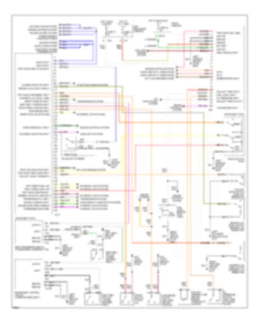
INTERIOR LIGHTS
Courtesy Lamps Wiring Diagram for Jaguar XJ6 L 1997
List of elements for Courtesy Lamps Wiring Diagram for Jaguar XJ6 L 1997:
- (0) off
- (i)
- (iii) start
- (left "a" post ground screw) g202
- (left console ground stud) g206
- (left heelboard ground screw) g304
- (logic ground stud) g401
- (parcel shelf ground screw) g904
- (right heelboard ground screw) g303
- 1996 vftc c 1996 vftc c
- Acc (i)
- Acc run (ii)
- Battery
- Body processor module (passengers underscuttle)
- Bt35
- Bt9
- Ca36
- Courtesy
- Driver door puddle lamp
- Driver door switch (door casing)
- Driver door switch pack (arm rest)
- Driver map lamp
- Fc1
- Fc2
- Fc3
- Fuse 10a
- Fuse 5a
- Glove box lamp
- Gnd
- Hot at all times
- Ignition switch
- Input
- Interior
- Interior lamps
- Interior lighting control
- Interior/map lamps console
- Key in
- Left e-post lamp
- Left rear door puddle lamp
- Left rear door switch (door casing)
- Left rear door switch pack (door casing)
- Left sunvisor lamp
- Left trunk lamp
- Lighting switches
- Map
- Note: "crank input" is used to switch off interior lamps during engine cranking
- Output
- Passenger door puddle lamp
- Passenger door switch (door casing)
- Passenger door switch pack (arm rest)
- Passenger map lamp
- Puddle lamp relay (left heelboard)
- Right e-post lamp
- Right heelboard fuse box
- Right rear door puddle lamp
- Right rear door switch (door casing)
- Right rear door switch pack (door casing)
- Right sunvisor lamp
- Right trunk lamp
- Run (ii)
- Security system
- Side lamps
- Trunk fuse box
- Trunk switch (trunk lid)
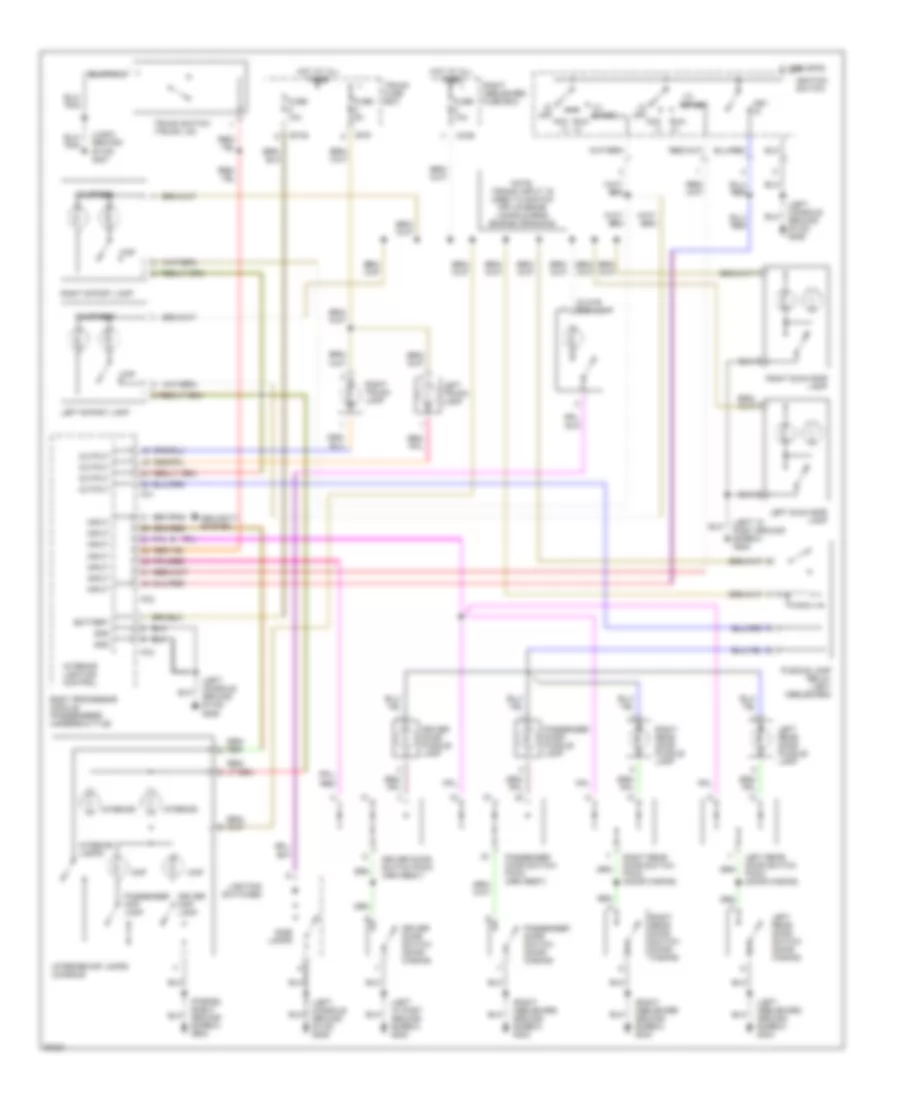
Instrument Illumination Wiring Diagram for Jaguar XJ6 L 1997
List of elements for Instrument Illumination Wiring Diagram for Jaguar XJ6 L 1997:
- (0) off
- (center console ground stud) g302
- (iii) start
- (left "a" post ground screw) g202
- (left console ground stud) g206
- (not used)
- (parcel shelf ground screw) g904
- (radio ground stud) g206
- (right console ground stud) g206
- (right heelboard ground screw) g303
- (right seat ground stud) g301
- 1996 vftc c
- Acc (i)
- Air conditioning control module (right side of a/c unit)
- Air conditioning control panel
- Ca107
- Ca108
- Ca2
- Cc10
- Cc16
- Cc17
- Cc2
- Cc9
- Center console switch pack (center console)
- Column switchgear
- Cruise locate
- Dimmer control
- Dimmer module
- Dimmer override
- Driver door switch pack (arm rest)
- Fascia switch pack
- Fc10
- Fc4
- Fc9
- Front cigar lighter (center console)
- Front fog locate
- Fuse 2 10a
- General illumiination
- General illumin- ation
- General illumination
- Gnd
- Ground stud) g302
- Hot at all times
- Ic1
- Ignition switch
- Input
- Instrument pack
- Interior/ map lamps console (roof console)
- Left heelboard fuse box
- Left rear door switch pack (door casing)
- Left rear seat heater switch (rear center console)
- Lighting switches
- Long wheel base
- Nca
- No code
- Output
- Override dimmer
- Passenger door switch pack (arm rest)
- Passenger fore/aft rear switches (lower front of seat)
- Passenger recline rear switches (lower front of seat)
- Passenger seat control module (passenger's seat)
- Radio
- Rear cigar lighter (center console)
- Rear fog locate
- Red/ pnk
- Red/pnk
- Red/pnk output
- Right rear door switch pack (door casing)
- Right rear seat heater switch (rear center console)
- Run (ii)
- Sc1
- Side lamps
- Sig gnd
- Sm1
- Sm6
- Traction locate
- Trip locate
- Trunk release locate
MEMORY SYSTEMS
Driver's Memory Seat Wiring Diagram (1 of 2) for Jaguar XJ6 L 1997
List of elements for Driver's Memory Seat Wiring Diagram (1 of 2) for Jaguar XJ6 L 1997:
- (driver's underscuttle) brake switch
- (iii) start
- (left "a" post ground screw) g202
- (left seat ground stud) g300
- (left side center console) hand brake switch
- (logig ground stud) g401
- Acc (i)
- Bt35
- Ca1
- Ca105
- Ca106
- Ca36
- Ca44
- Center console switch pack
- Computer data lines system
- Data
- Driver seat control module (driver's seat)
- Driver seat heater switch
- Driver seat motors (driver's seat)
- Fuse 10a
- Fuse 3 20a
- Fuse 4 20a
- Fuse 5a
- Fuse 9 25a
- G206 (left console ground stud)
- Gnd
- Ground stud) g302
- Ground stud) g401
- Headrest raise/lower
- Hot at all times
- Hot in run & start
- Ignition switch
- Input
- Key in
- Left heel- board fuse box
- Memory systems (mirrors)
- Memory systems (mirrors) & anti-theft system)
- Memory systems (passenger seats) & warning systems
- Off
- Output
- Pnk
- Red
- Right heelboard fuse box
- Run (ii)
- Seat fore/aft
- Seat front raise/lower
- Seat rear raise/lower
- Sig gnd
- Sm1
- Sm11
- Sm13
- Sm2
- Sm3
- Sm4
- Sm6
- Squab recline fore/aft
- State
- Trunk fuse box
Driver's Memory Seat Wiring Diagram (2 of 2) for Jaguar XJ6 L 1997
List of elements for Driver's Memory Seat Wiring Diagram (2 of 2) for Jaguar XJ6 L 1997:
- (center console ground stud) g302
- (left "a" post ground screw) g202
- (left console ground stud) g206
- (not used)
- Aft
- Anti-theft system (security & locking control module)
- Battery
- Body processor module (passenger's underscuttle)
- Dd1
- Dd2
- Down
- Driver door switch (door casing)
- Driver door switch pack (arm rest)
- Driver seat cushion (under driver's seat)
- Driver seat lumbar pump (driver's seat)
- Driver seat switch pack (driver's seat)
- Driver squab (driver's seat)
- Fc1
- Fc2
- Fc3
- Fore
- Gnd
- Head rest
- Heater
- Inner cushion heater
- Input
- Lower
- Lumbar
- Memory switches
- Memory systems (mirrors) (column/mirror movement control module)
- Nca
- Not-in-park microswitch ("j" gate, center console)
- Outer cushion heater
- Output
- Pressure switch
- Raise
- Recline
- Red
- Seat
- Seat front
- Seat rear
- Set memory status
- Sm5
- Solenoid valve
- Solid state
- Thermostat
Memory Mirrors & Steering Column Movement (1 of 2) for Jaguar XJ6 L 1997
List of elements for Memory Mirrors & Steering Column Movement (1 of 2) for Jaguar XJ6 L 1997:
- ("j" gate, center console) not in-park microswitch
- (center console ground stud) g302
- (iii) start
- (left "a" post ground screw) g202
- (left console ground stud) g206
- (left side center console) hand brake switch
- (logic ground stud) g401
- Acc (i)
- Auto tilt switch
- Ca1
- Ca2
- Ca44
- Column joy stick
- Column switchgear
- Column/mirror movement control module (right underscuttle)
- Computer data lines system
- Data
- Dd1
- Driver door switch (door casing)
- Driver door switch pack (arm rest)
- Fc4
- Fc45
- Fc46
- Fc47
- Fc49
- Fc50
- Fuse 13 15a
- Fuse 2 5a
- Fuse 6 5a
- G206 (left console ground stud)
- Gnd
- Hot at all times
- Ignition switch
- Input
- Key in
- Left heelboard fuse box
- Memory systems (driver's seat)
- Memory systems (driver's seat) & anti-theft system
- Nca
- Off
- Output
- Pnk
- Reach
- Red
- Right heelboard fuse box
- Run (ii)
- Sc5
- Sig gnd
- Steering column motors (steering column)
- Tilt
Memory Mirrors & Steering Column Movement (2 of 2) for Jaguar XJ6 L 1997
List of elements for Memory Mirrors & Steering Column Movement (2 of 2) for Jaguar XJ6 L 1997:
- (center console ground stud) g302
- (left "a" post ground screw) g202
- 4.0l engine
- 4.0l supercharged
- Anti-theft system
- Dd1
- Dd2
- Driver door mirror motors (mirror assembly)
- Driver door switch pack (arm rest)
- Driver right/ left
- Driver up/ down
- Linear gear position switches ("j" gate/ center console)
- Memory switches
- Memory systems (driver's seat)
- Mirror joy stick
- Mirror select
- Nca
- Passenger door mirror motors (mirror assembly)
- Passenger right/left
- Passenger up/down
- Pnk
- Right/ left
- Rotary switch ("j" gate/ center console)
- Set memory status
- Up/down
Passenger's Memory Seat Wiring Diagram (1 of 2) for Jaguar XJ6 L 1997
List of elements for Passenger's Memory Seat Wiring Diagram (1 of 2) for Jaguar XJ6 L 1997:
- (0) off
- (iii) start
- (inside lower front of seat) passenger seat fore/aft rear switches
- (right heelboard ground screw) g303
- (right seat ground stud) g301
- Acc (i)
- Bt35
- Ca1
- Ca107
- Ca108
- Ca2
- Ca36
- Ca44
- Center console switch pack
- Computer data lines system
- Data
- Fuse 10a
- Fuse 20a
- Fuse 25a
- Fuse 5a
- G206 (left console ground stud)
- Gnd
- Ground stud) g302
- Ground stud) g401
- Headrest raise/lower
- Hot at all times
- Hot in run & start
- Ignition
- Ignition switch
- Input
- Interior lights system
- Key in
- Left heelboard fuse box
- Long wheel base
- Long wheel base
- Memory systems (driver seats) & warning systems
- Output
- Passenger seat control module (passenger's seat)
- Passenger seat heater switch
- Passenger seat motors (passenger's seat)
- Pl1
- Pnk
- Red
- Red/pnk
- Right heel- board fuse box
- Run (ii)
- Seat fore/aft
- Seat front raise/lower
- Seat rear raise/lower
- Sig gnd
- Sm1
- Sm11
- Sm13
- Sm2
- Sm3
- Sm4
- Sm6
- Squab recline fore/aft
- State
- Trunk fuse box
Passenger's Memory Seat Wiring Diagram (2 of 2) for Jaguar XJ6 L 1997
List of elements for Passenger's Memory Seat Wiring Diagram (2 of 2) for Jaguar XJ6 L 1997:
- (inside lower front of seat) passenger seat recline rear switches
- (left console ground stud) g206
- (not used)
- (right heelboard ground screw) g303
- Aft
- Battery
- Body processor module (passenger's underscuttle)
- Down
- Fc1
- Fc2
- Fc3
- Fore
- Gnd
- Head rest
- Heater
- Inner cushion heater
- Input
- Long wheel base
- Lower
- Lumbar
- Memory switches
- Outer cushion heater
- Output
- Passenger door switch (door casing)
- Passenger door switch pack (arm rest)
- Passenger seat cushion (under passenger's seat)
- Passenger seat lumbar pump (passenger's seat)
- Passenger seat switch pack (passenger's seat)
- Passenger squab (passenger's seat)
- Pd1
- Pressure switch
- Raise
- Recline
- Red
- Seat
- Seat front
- Seat rear
- Set memory status
- Sm5
- Solenoid valve
- Solid state
- Thermostat
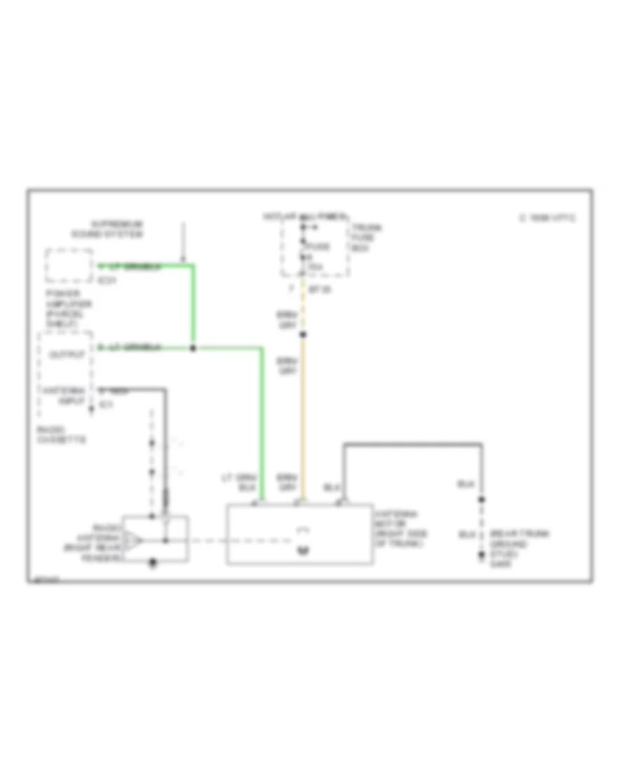
POWER ANTENNA
Power Antenna Wiring Diagram for Jaguar XJ6 L 1997
List of elements for Power Antenna Wiring Diagram for Jaguar XJ6 L 1997:
- (rear trunk ground stud) g405
- 1996 vftc c
- Antenna input
- Antenna motor (right side of trunk)
- Bt35
- Fuse 15a
- Hot at all times
- Ic1
- Ic31
- Nca
- Output
- Power amplifier (parcel shelf)
- Radio antenna (right rear fender)
- Radio cassette
- Trunk fuse box
- W/premium sound system
POWER DISTRIBUTION
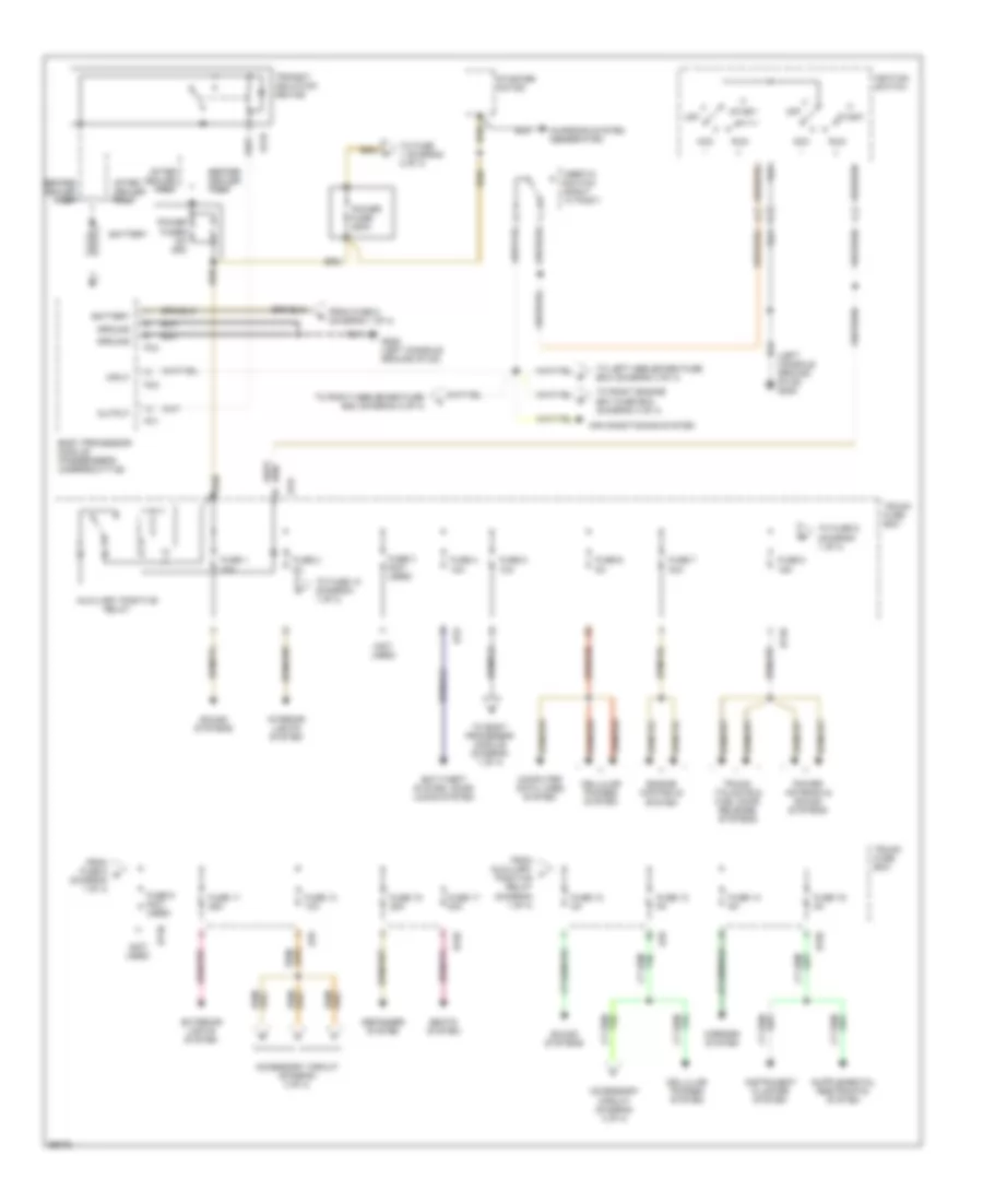
Power Distribution Wiring Diagram (1 of 4) for Jaguar XJ6 L 1997
List of elements for Power Distribution Wiring Diagram (1 of 4) for Jaguar XJ6 L 1997:
- (left console ground stud) g206
- (not used)
- Acc
- Accessory circuit (diagram 4 of 4)
- After dealer prep
- Air conditioning system
- Anti-theft system, door locks system
- Auxiliary positive relay
- Battery
- Before dealer prep
- Body processor module (passenger's underscuttle)
- Bt35
- Bt37
- Bt9
- Cellular phones system
- Charging system (generator)
- Computer data lines system
- Defogger system
- Engine controls system
- Exterior lights system
- Fc1
- Fc2
- Fc3
- From auxiliary f positive relay (diagram 1 of 4)
- From fuse 5 (diagram 1 of 4)
- From fuse 8 g (diagram 1 of 4)
- Fuse 1 25a
- Fuse 10 5a
- Fuse 11 25a
- Fuse 12 5a
- Fuse 13 10a
- Fuse 14 5a
- Fuse 15 25a
- Fuse 16 5a
- Fuse 17 20a
- Fuse 2 5a
- Fuse 3 (not used)
- Fuse 4 10a
- Fuse 5 10a
- Fuse 6 5a
- Fuse 7 30a
- Fuse 8 15a
- Fuse 9 (not used)
- G206 (left console ground stud)
- Ground
- Ignition switch
- Iii
- Inertia switch (right "a" post)
- Input
- Instrument cluster system
- Interior lights system
- Mirrors system
- Off
- Output
- Power antenna & sound systems
- Power fuse 250a
- Power fuses (2x 250)
- Run
- Seats system
- Sound systems
- Start
- Starter motor
- To body processor module (diagram 1 of 4)
- To fuse 1 (diagram 2 of 4)
- To fuse 10 (diagram 1 of 4)
- To fuse 9 (diagram 1 of 4)
- To left heelboard fuse box (diagram 3 of 4)
- To right engine bay fuse box (diagram 4 of 4)
- To right heelboard fuse box (diagram 2 of 4)
- Transit isolation device
- Trunk fuse box
- Trunk, tailgate & fuel door release systems
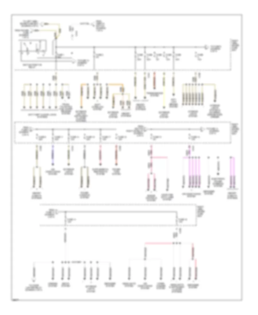
Power Distribution Wiring Diagram (2 of 4) for Jaguar XJ6 L 1997
List of elements for Power Distribution Wiring Diagram (2 of 4) for Jaguar XJ6 L 1997:
- (diagram 2 of 4)
- Air conditioning system
- Anti- lock brakes system
- Anti-theft & door locks systems
- Ca36
- Ca44
- Computer data lines system
- Defogger system
- Electronic power steering system
- Engine controls system
- Exterior lights & instrument cluster systems
- Exterior lights system
- From fuse 12 l (diagram 2 of 4)
- From fuse 8 k (diagram 2 of 4)
- From ignition positive relay (diagram 2 of 4)
- From inertia switch (diagram 1 of 4)
- From power fuse (diagram 1 of 4)
- Fuse 1 15a
- Fuse 10 5a
- Fuse 10a
- Fuse 11 20a
- Fuse 12 10a
- Fuse 13 10a
- Fuse 14 10a
- Fuse 15 30a
- Fuse 16 10a
- Fuse 17 15a
- Fuse 18 15a
- Fuse 2 5a
- Fuse 20a
- Fuse 30a
- Fuse 5a
- Fuse 9 25a
- Headlights & instrument cluster systems
- Headlights system
- Ignition positive relay
- Interior lights system
- Interior lights system & universal garage door opener
- Memory & seats systems
- Memory systems
- Mirrors system
- Power tops system
- Power windows system
- Right heel- board fuse box
- Seats system
- Shift interlock system
- To cigar lighter relay (diagram 4 of 4)
- To fuse 10 (diagram 2 of 4)
- To fuse 14
- To fuse 9 (diagram 2 of 4)
- To left heel- board fuse box (diagram 3 of 4)
- Transmissions system
- Trunk, tailgate & fuel doors release system
- Wiper/ washer system
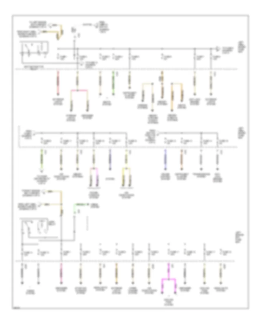
Power Distribution Wiring Diagram (3 of 4) for Jaguar XJ6 L 1997
List of elements for Power Distribution Wiring Diagram (3 of 4) for Jaguar XJ6 L 1997:
- Air conditioning system
- Anti- lock brakes system
- Anti-lock brakes system
- Ca1
- Ca2
- Cooling fans system
- Cruise control system
- Defogger system
- Exterior lights system
- From fuse 8 p (diagram 3 of 4)
- From ignition o positive relay (diagram 3 of 4)
- From inertia switch (diagram 1 of 4)
- From left heel- board fuse box (diagram 3 of 4)
- From right heel- board fuse box (diagram 2 of 4)
- Fuse 1 10a
- Fuse 1 25a
- Fuse 10 10a
- Fuse 10 5a
- Fuse 11 20a
- Fuse 11 30a
- Fuse 12 5a
- Fuse 13 15a
- Fuse 14 10a
- Fuse 15 25a
- Fuse 15 30a
- Fuse 16 5a
- Fuse 17 10a
- Fuse 17 30a
- Fuse 18 10a
- Fuse 18 15a
- Fuse 2 10a
- Fuse 3 20a
- Fuse 3 25a
- Fuse 4 10a
- Fuse 4 20a
- Fuse 5 10a
- Fuse 5 5a
- Fuse 6 20a
- Fuse 6 5a
- Fuse 7 30a
- Fuse 8 10a
- Fuse 8 15a
- Fuse 9 20a
- Headlights system
- Horn relay
- Horns system
- Ignition positive relay
- Instrument cluster system
- Interior lights system
- Left engine bay fuse box
- Left heel- board fuse box
- Ls1
- Ls37
- Memory & power window systems
- Memory & seats systems
- Memory systems
- Mirrors systems
- Power windows system
- Seats system
- Starting/ charging system
- System
- To cigar lighter relay (diagram 4 of 4)
- To fuse 10 (diagram 3 of 4)
- To fuse 9 (diagram 3 of 4)
- To left engine bay fuse box (diagram 3 of 4)
- To right engine bay fuse box (diagram 4 of 4)
- Transmissions system
- Wiper/ washer system
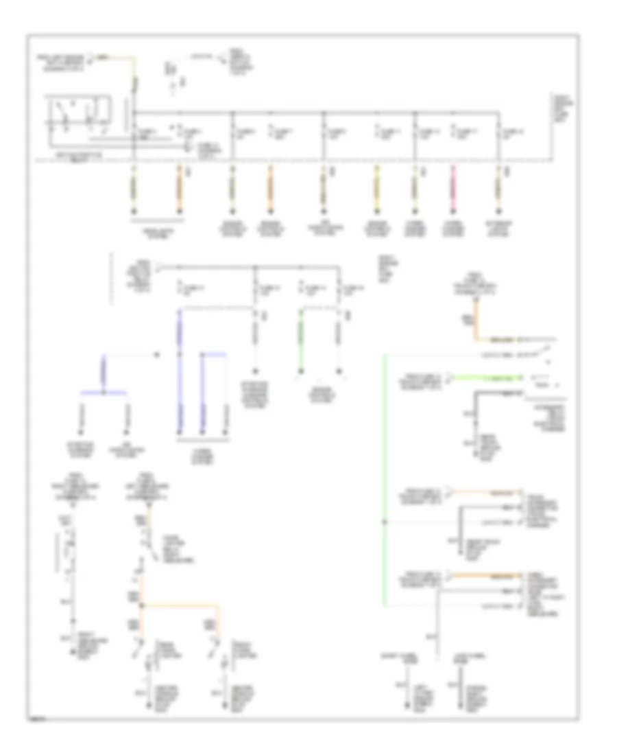
Power Distribution Wiring Diagram (4 of 4) for Jaguar XJ6 L 1997
List of elements for Power Distribution Wiring Diagram (4 of 4) for Jaguar XJ6 L 1997:
- (1)
- (2)
- (3)
- (5)
- (center console ground stud) g302
- (left "a" post ground screw) g202
- (parcel shelf ground screw) g904
- (rear trunk ground stud) g405
- (right heelboard ground screw) g303
- Accessory relay (trunk electrical carrier)
- Air conditioning system
- Cabin accessory connector (swb) (left "a" post) (lwb) (right heelboard)
- Cigar lighter relay (right heelboard)
- Engine controls system
- Exterior lights system
- From fuse 12, trunk fuse box (diagram 1 of 4)
- From fuse 13, trunk fuse box (diagram 1 of 4)
- From fuse 14, right heelboard fuse box (diagram 2 of 4)
- From fuse 9, left heelboard fuse box (diagram 3 of 4)
- From ignition positive relay (diagram 4 of 4)
- From inertia switch (diagram 1 of 4)
- From left engine bay fuse box (diagram 3 of 4)
- Front cigar lighter
- Fuse 10 (diagram 4 of 4)
- Fuse 10 5a
- Fuse 11 20a
- Fuse 12 10a
- Fuse 13 10a
- Fuse 14 10a
- Fuse 16 10a
- Fuse 17 30a
- Fuse 18 5a
- Fuse 2 15a
- Fuse 4 10a
- Fuse 6 5a
- Fuse 7 25a
- Fuse 8 10a
- Headlights system
- Ignition positive relay
- Long wheel base
- Rear cigar lighter
- Right engine bay fuse box
- Rs1
- Rs6
- Short wheel base
- Starting/ charging & engine controls system
- Starting/ charging system
- Trunk accessory connector (trunk electrical carrier)
- Wiper/ washer system
POWER DOOR LOCKS
Power Door Lock Wiring Diagram for Jaguar XJ6 L 1997
List of elements for Power Door Lock Wiring Diagram for Jaguar XJ6 L 1997:
- (center console ground stud) g302
- (left console ground stud) g206
- (left heelboard ground screw) g304
- (logic ground stud) g401
- (parcel shelf ground screw) g904
- (right "a" post) inertia switch
- (right heelboard ground screw) g303
- 10(5)
- 6(1)
- 7(2)
- 8(3)
- 9(4)
- Acc
- All close switch
- Bt9
- Ca18
- Ca19
- Ca20
- Ca21
- Ca44
- Center console switch pack
- Computer data lines system
- Data
- Door lock relay (left side of heelboard)
- Door unlock relay (left side of heelboard)
- Driver door key barrel switch
- Driver door lock actuator (inside driver's door)
- Driver door unlock relay (left side of heelboard)
- Fuse 1 15a
- Fuse 4 10a
- G401 (logic ground stud)
- Gnd
- Hot at all times
- Ignition switch
- Input
- Instrument cluster system
- Key in
- Left rear door lock actuator (inside left rear door)
- Lock
- Lock status
- Nca
- Not in-park microswitch (center console, "j" gate)
- Off
- Output
- Passenger door lock actuator (inside passenger's door)
- Pnk
- Power
- Power distribution system
- Right heelboard fuse box
- Right rear door lock actuator (inside right rear door)
- Run
- Security & locking control module (left front of trunk)
- Start
- Trunk fuse box
- Trunk, tailgate & fuel doors systems
- Unlock
- Valet switch (center console glove box)
POWER MIRRORS
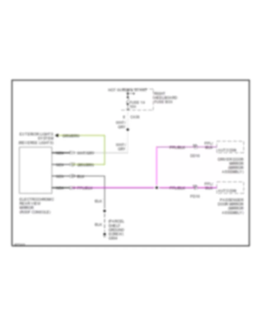
Electrochromic Rear View Mirror Wiring Diagram for Jaguar XJ6 L 1997
List of elements for Electrochromic Rear View Mirror Wiring Diagram for Jaguar XJ6 L 1997:
- (parcel shelf ground screw) g904
- Auto dim
- Ca36
- Dd10
- Driver door mirror (mirror assembly)
- Electrochromic rear view mirror (roof console)
- Exterior lights system (reverse lights)
- Fuse 14 10a
- Hot in run & start
- Nca
- Passenger door mirror (mirror assembly)
- Pd10
- Right heelboard fuse box
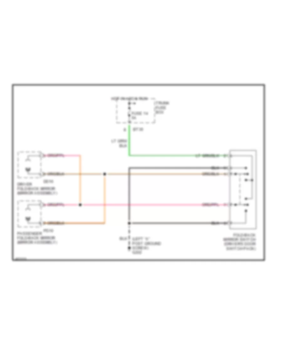
Fold-back Mirrors Wiring Diagram for Jaguar XJ6 L 1997
List of elements for Fold-back Mirrors Wiring Diagram for Jaguar XJ6 L 1997:
- Bt35
- Dd10
- Driver fold-back mirror (mirror assembly)
- Fold-back mirror switch (driver's door switch pack)
- Fuse 14 5a
- Hot in acc & run
- Passenger fold-back mirror (mirror assembly)
- Pd10
- Trunk fuse box
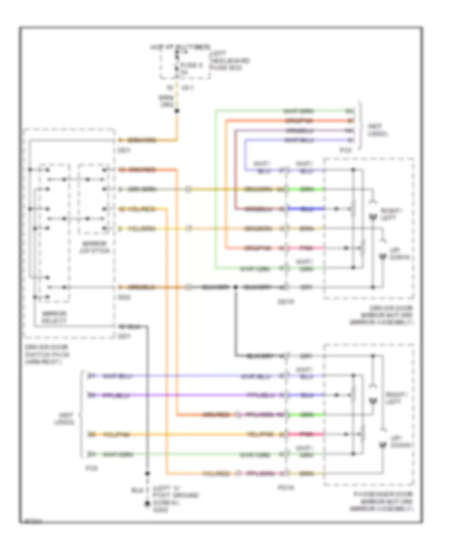
Power Mirrors Wiring Diagram for Jaguar XJ6 L 1997
List of elements for Power Mirrors Wiring Diagram for Jaguar XJ6 L 1997:
- (left "a" post ground screw) g202
- (not used)
- Ca1
- Dd1
- Dd10
- Dd2
- Driver door mirror motors (mirror assembly)
- Driver door switch pack (arm rest)
- Fc5
- Fc6
- Fuse 6 5a
- Hot at all times
- Left heelboard fuse box
- Mirror joystick
- Mirror select
- Passenger door mirror motors (mirror assembly)
- Pd10
- Pnk
- Right/ left
- Up/ down
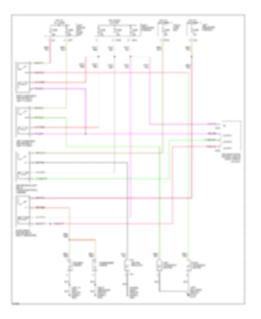
POWER SEATS
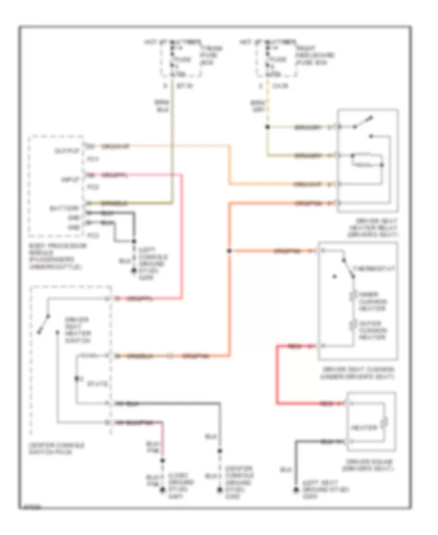
Driver's Heated Seat Wiring Diagram for Jaguar XJ6 L 1997
List of elements for Driver's Heated Seat Wiring Diagram for Jaguar XJ6 L 1997:
- (center console ground stud) g302
- (left console ground stud) g206
- (left seat ground stud) g300
- (logic ground stud) g401
- Battery
- Body processor module (passenger's underscuttle)
- Bt35
- Ca36
- Center console switch pack
- Driver seat cushion (under driver's seat)
- Driver seat heater relay (driver's seat)
- Driver seat heater switch
- Driver squab (driver's seat)
- Fc1
- Fc2
- Fc3
- Fuse 10a
- Fuse 25a
- Gnd
- Heater
- Hot at all times
- Inner cushion heater
- Input
- Outer cushion heater
- Output
- Red
- Right heelboard fuse box
- State
- Thermostat
- Trunk fuse box
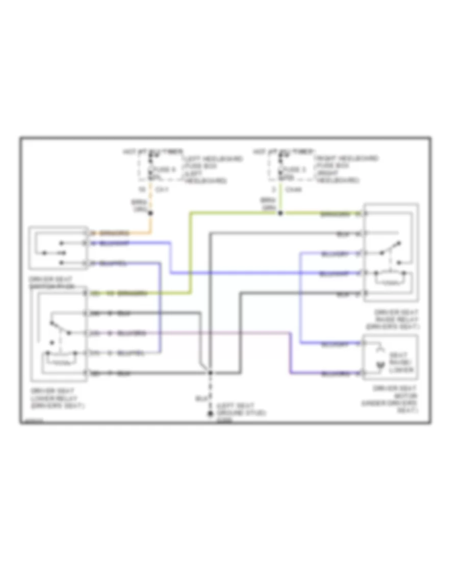
Driver's Raise/Lower Wiring Diagram for Jaguar XJ6 L 1997
List of elements for Driver's Raise/Lower Wiring Diagram for Jaguar XJ6 L 1997:
- (1)
- (2)
- (3)
- (4)
- (5)
- (left seat ground stud) g300
- Ca1
- Ca44
- Driver seat lower relay (driver's seat)
- Driver seat motor (under driver's seat)
- Driver seat raise relay (driver's seat)
- Driver seat switch pack
- Fuse 3 20a
- Fuse 6 5a
- Hot at all times
- Left heelboard fuse box (left heelboard)
- Right heelboard fuse box (right heelboard)
- Seat raise/ lower
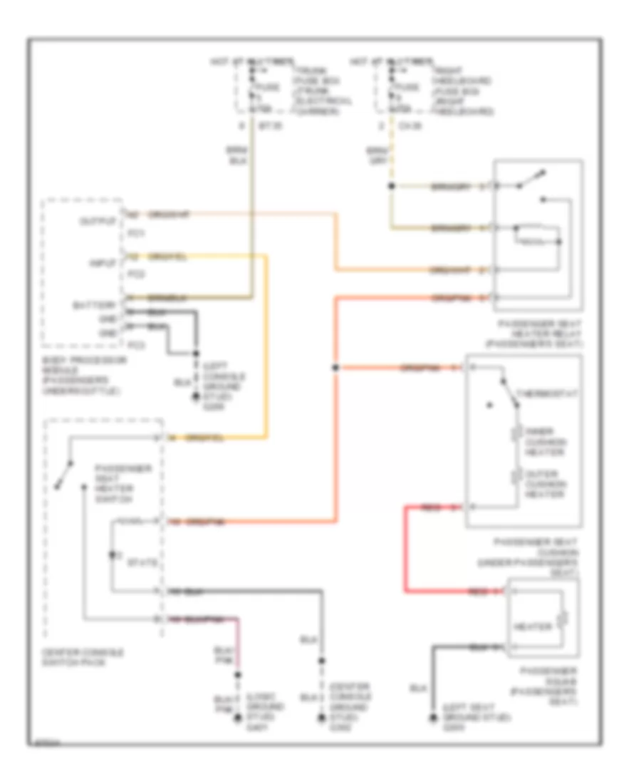
Passenger's Heated Seat Wiring Diagram for Jaguar XJ6 L 1997
List of elements for Passenger's Heated Seat Wiring Diagram for Jaguar XJ6 L 1997:
- (center console ground stud) g302
- (left console ground stud) g206
- (left seat ground stud) g300
- (logic ground stud) g401
- Battery
- Body processor module (passenger's underscuttle)
- Bt35
- Ca36
- Center console switch pack
- Fc1
- Fc2
- Fc3
- Fuse 10a
- Fuse 25a
- Gnd
- Heater
- Hot at all times
- Inner cushion heater
- Input
- Outer cushion heater
- Output
- Passenger seat cushion (under passenger's seat)
- Passenger seat heater relay (passenger's seat)
- Passenger seat heater switch
- Passenger squab (passenger's seat)
- Red
- Right heelboard fuse box (right heelboard)
- State
- Thermostat
- Trunk fuse box (trunk electrical carrier)
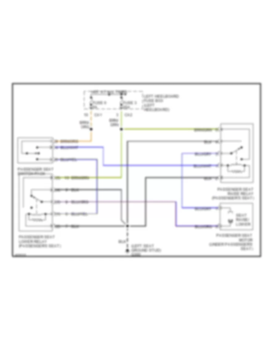
Passenger's Raise/Lower Wiring Diagram for Jaguar XJ6 L 1997
List of elements for Passenger's Raise/Lower Wiring Diagram for Jaguar XJ6 L 1997:
- (1)
- (2)
- (3)
- (4)
- (5)
- (left seat ground stud) g300
- Ca1
- Ca2
- Fuse 3 20a
- Fuse 6 5a
- Hot at all times
- Left heelboard fuse box (left heelboard)
- Passenger seat lower relay (passenger's seat)
- Passenger seat motor (under passenger's seat)
- Passenger seat raise relay (passenger's seat)
- Passenger seat switch pack
- Seat raise/ lower
Rear Heated Seats Wiring Diagram for Jaguar XJ6 L 1997
List of elements for Rear Heated Seats Wiring Diagram for Jaguar XJ6 L 1997:
- (right seat ground stud) g301 (lwb) g300 (swb) (left seat ground stud)
- 1996 vftc c
- 31b
- Bt35
- Ca36
- Fuse 14 10a
- Fuse 17 20a
- Heater
- Hot at all times
- Hot in run & start
- Left rear seat cushion (inside left rear seat)
- Left rear seat heater switch (center console)
- Left rear seat heater timer (left heelboard)
- Left rear seat squab (inside left rear seat)
- Red
- Right heelboard fuse box (right heelboard)
- Right rear seat cushion (inside right rear seat)
- Right rear seat heater switch (center console)
- Right rear seat heater timer (right heelboard)
- Right rear seat squab (inside right rear seat)
- State
- Thermostat
- Timer
- Trunk fuse box (trunk electrical carrier)
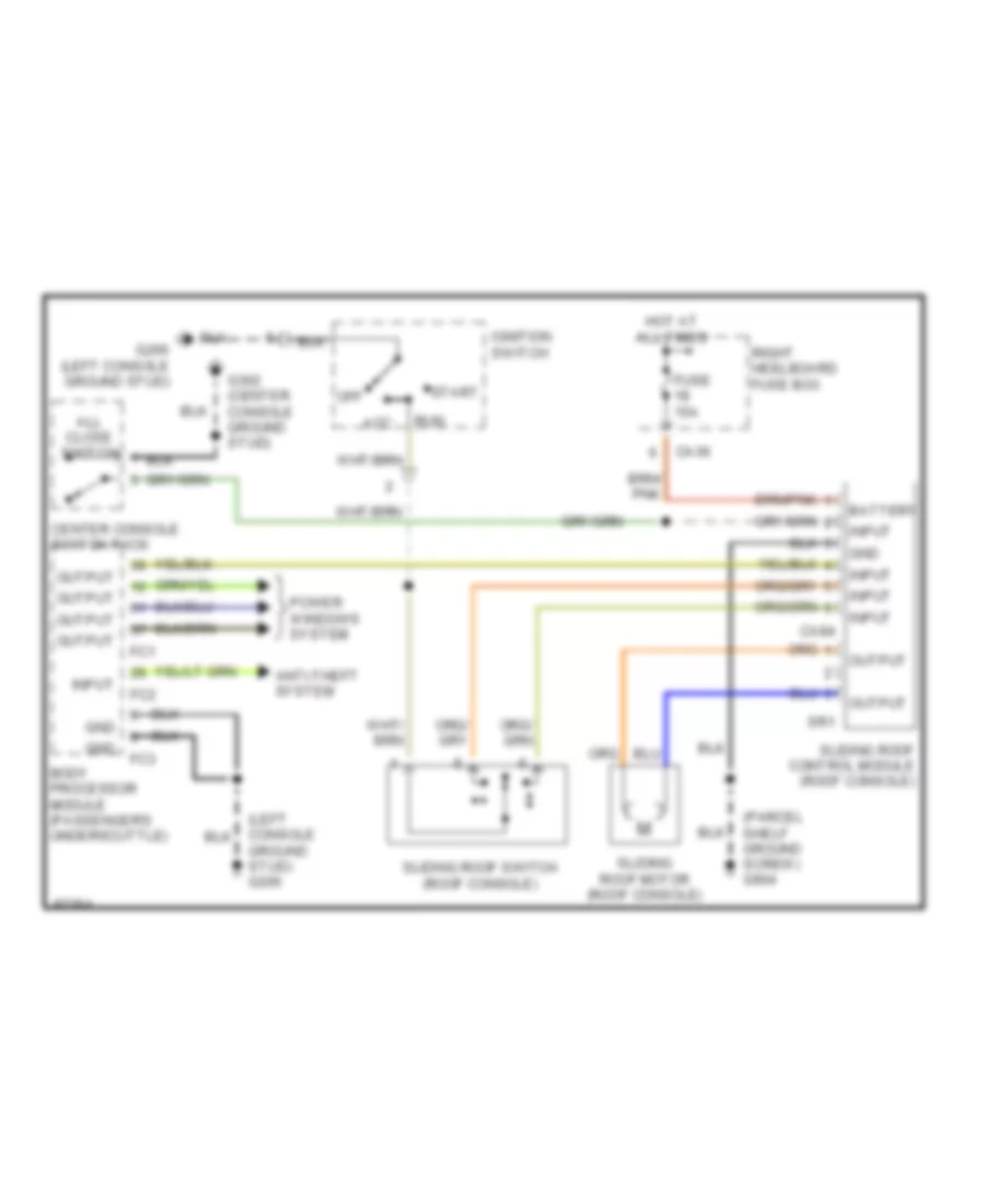
POWER TOP/SUNROOF
Power Top/Sunroof Wiring Diagrams for Jaguar XJ6 L 1997
List of elements for Power Top/Sunroof Wiring Diagrams for Jaguar XJ6 L 1997:
- (parcel shelf ground screw) g904
- Acc
- All close switch
- Anti-theft system
- Battery
- Body processor module (passenger's underscuttle)
- Ca36
- Ca84
- Center console switch pack
- Fc1
- Fc2
- Fc3
- Fuse 15a
- G206 (left console ground stud)
- G302 (center console ground stud)
- Gnd
- Ground stud) g206
- Hot at all times
- Ignition switch
- Input
- Off
- Output
- Power windows system
- Right heelboard fuse box
- Run
- Sliding roof control module (roof console)
- Sliding roof motor (roof console)
- Sliding roof switch (roof console)
- Sr1
- Start
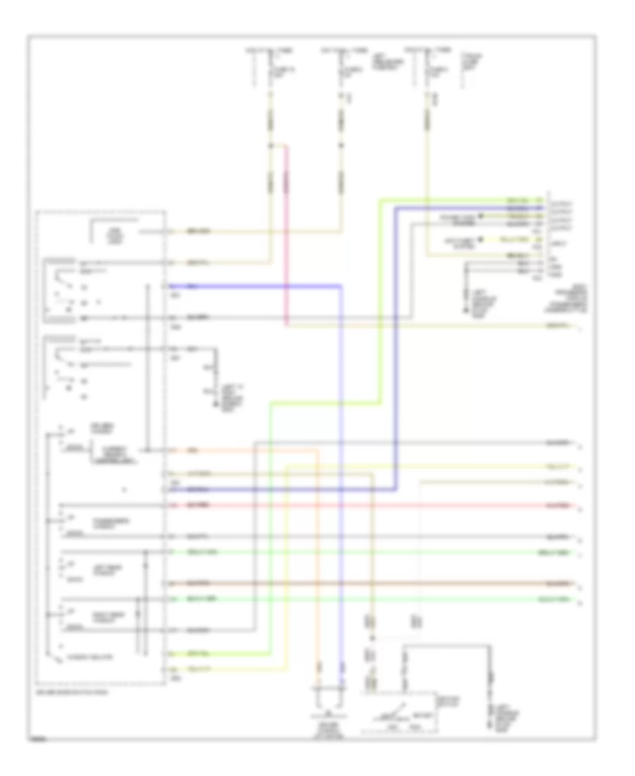
POWER WINDOWS
Power Window Wiring Diagram (1 of 2) for Jaguar XJ6 L 1997
List of elements for Power Window Wiring Diagram (1 of 2) for Jaguar XJ6 L 1997:
- (left "a" post ground screw) g202
- (left console ground stud) g206
- 87a
- Acc
- Anti-theft system
- Body processor module (passenger's underscuttle)
- Bt35
- Ca1
- Current sense & control unit
- Dd1
- Dd2
- Down
- Driver door switch pack
- Driver window lift motor
- Driver's window
- Fc1
- Fc2
- Fc3
- Fuse 15 30a
- Fuse 5 10a
- Fuse 6 5a
- Gnd
- Hot at all times
- Ignition switch
- Input
- Left heelboard fuse box
- Left rear window
- Off
- One touch logic
- Output
- Passenger's window
- Power tops system
- Right rear window
- Run
- Start
- Trunk fuse box
- Window isolate
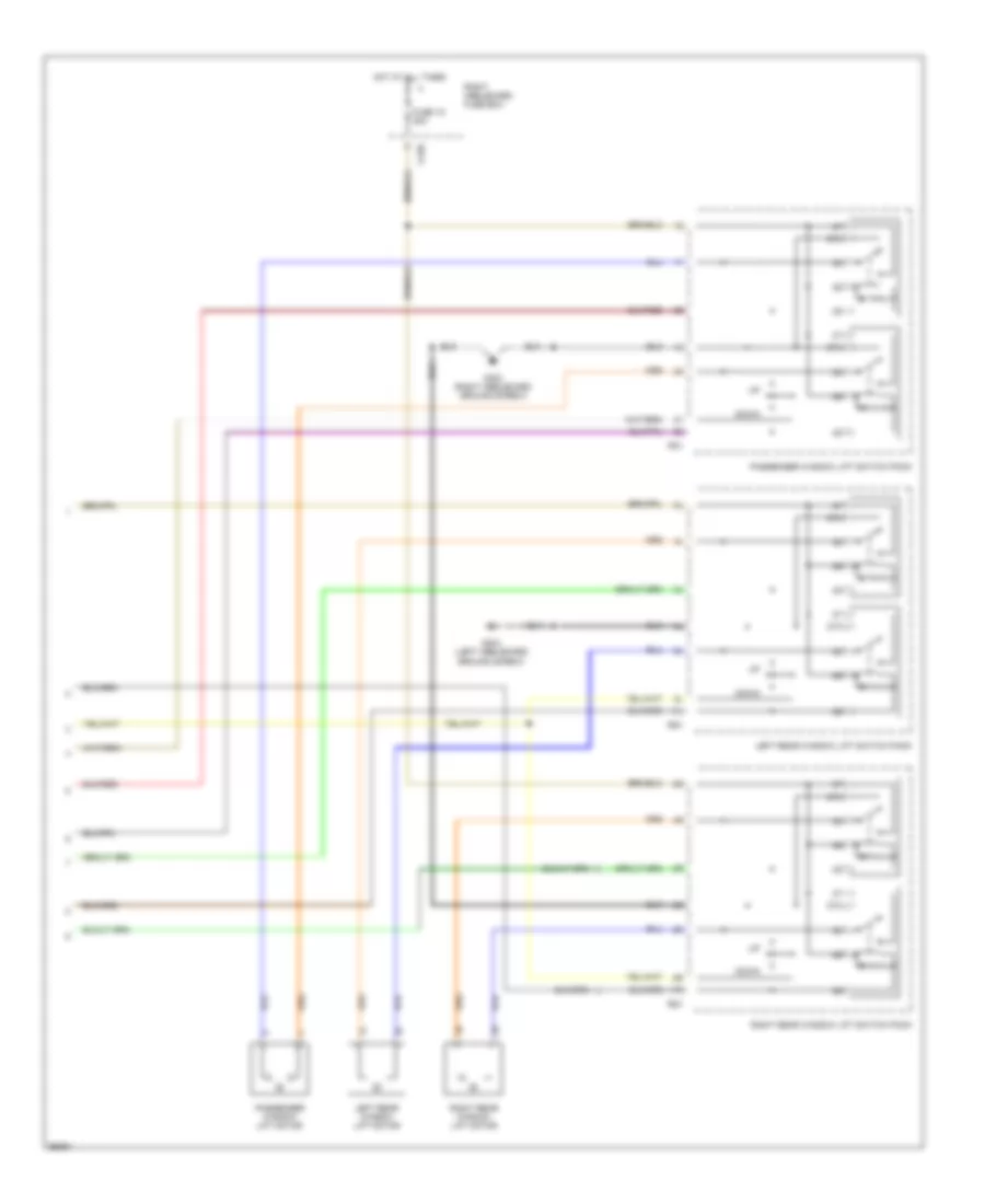
Power Window Wiring Diagram (2 of 2) for Jaguar XJ6 L 1997
List of elements for Power Window Wiring Diagram (2 of 2) for Jaguar XJ6 L 1997:
- 11l
- 11r
- 87a
- Ca36
- Down
- Fuse 15 30a
- G303 (right heelboard ground screw)
- G304 (left heelboard ground screw)
- Hot at all times
- Left rear window lift motor
- Left rear window lift switch pack
- Passenger window lift motor
- Passenger window lift switch pack
- Pd1
- Rd1
- Right heelboard fuse box
- Right rear window lift motor
- Right rear window lift switch pack
RADIO
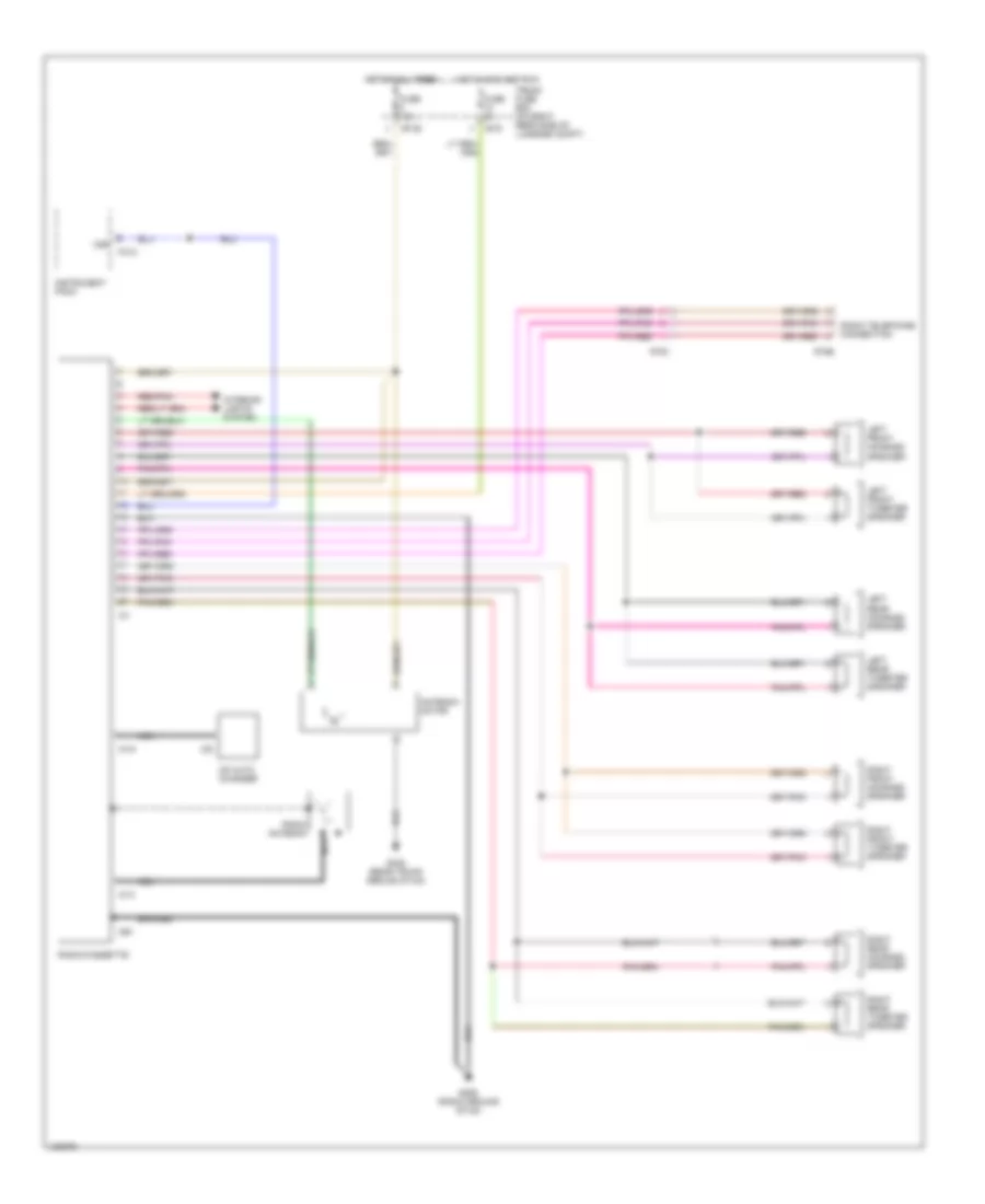
Radio Wiring Diagrams, Base Radio for Jaguar XJ6 L 1997
List of elements for Radio Wiring Diagrams, Base Radio for Jaguar XJ6 L 1997:
- Antenna motor
- Braided
- Bt35
- Bt9
- Cd auto changer
- Ce1
- Fc10
- Fuse 15a
- Fuse 5a
- G206 (radio ground stud)
- G405 (rear trunk ground stud)
- Hot at all times hot at all times
- Hot in acc and run
- Ic1
- Ic13
- Ic19
- Ic5
- Instrument pack
- Interior lights system
- Left front mid-bass speaker
- Left front tweeter speaker
- Left rear mid-bass speaker
- Left rear tweeter speaker
- Nca
- Radio antenna
- Radio telephone connection
- Radio/cassette
- Red/pnk
- Right front mid-bass speaker
- Right front tweeter speaker
- Right rear mid-bass speaker
- Right rear tweeter speaker
- Rt61
- Rt66
- Trunk fuse box (on right rear side of luggage compt)
- Vss
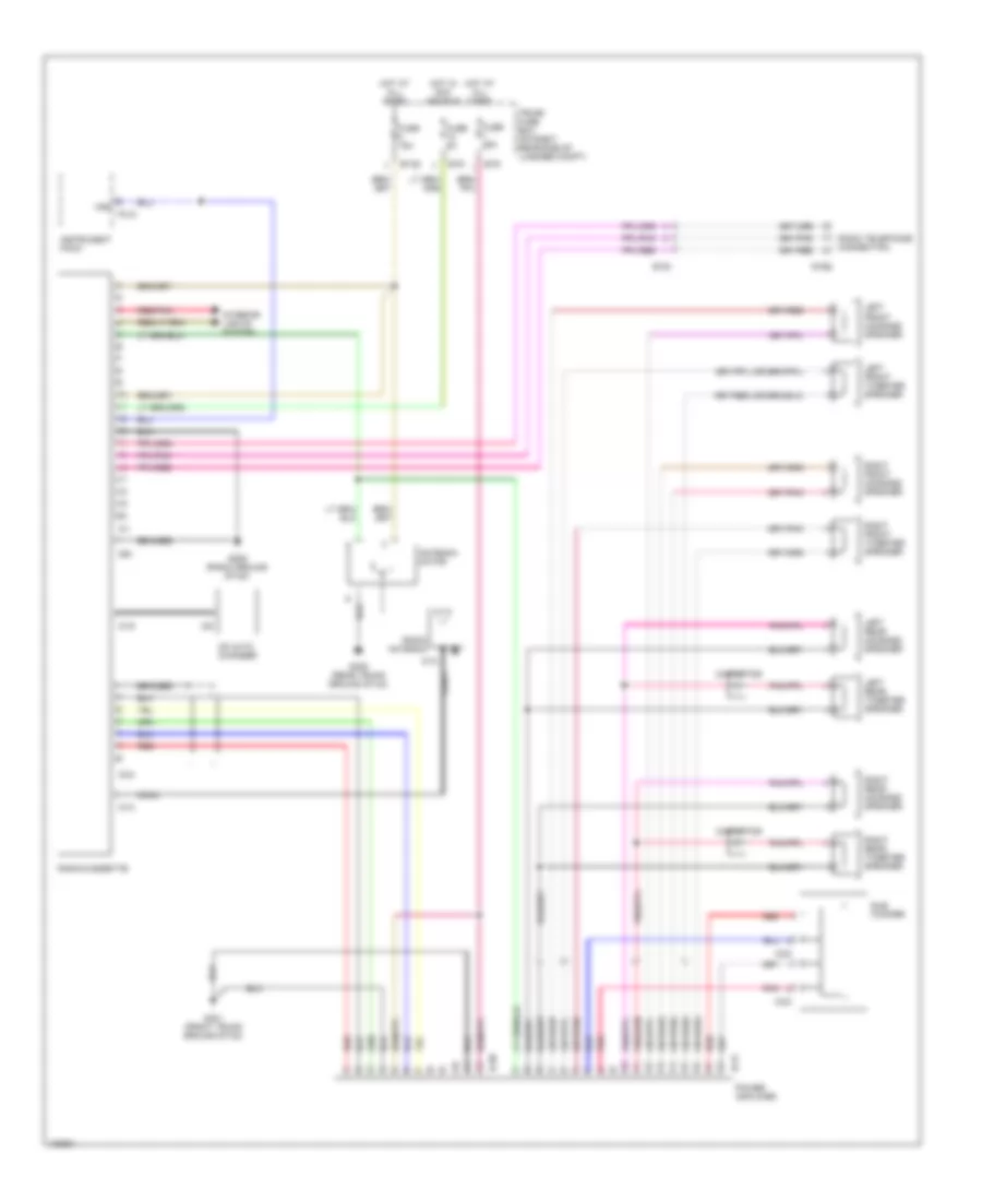
Radio Wiring Diagrams, Premium Radio for Jaguar XJ6 L 1997
List of elements for Radio Wiring Diagrams, Premium Radio for Jaguar XJ6 L 1997:
- Antenna motor
- Braided
- Bt35
- Bt9
- Caox
- Capacitor
- Cd auto changer
- Ce1
- Coax
- Fc10
- Fuse 15a
- Fuse 25a
- Fuse 5a
- G206 (radio ground stud)
- G401 (front trunk ground stud)
- G405 (rear trunk ground stud)
- Hot at all times
- Hot in acc and run
- Ic1
- Ic12
- Ic13
- Ic19
- Ic30
- Ic31
- Ic32
- Ic33
- Ic34
- Ic5
- Instrument pack
- Interior lights system
- Left front mid-bass speaker
- Left front tweeter speaker
- Left rear mid-bass speaker
- Left rear tweeter speaker
- Pnk
- Power amplifier
- Radio antenna
- Radio telephone connection
- Radio/cassette
- Red
- Red/pnk
- Right front mid-bass speaker
- Right front tweeter speaker
- Right rear mid-bass speaker
- Right rear tweeter speaker
- Rt61
- Rt66
- Sub woofer
- Trunk fuse box (on right rear side of luggage compt)
- Vss
SHIFT INTERLOCKS
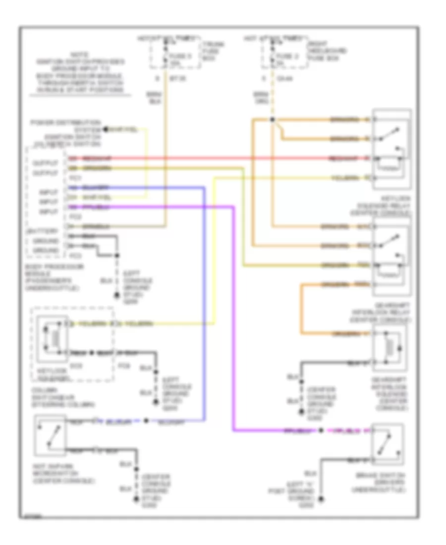
Shift Interlock Wiring Diagram for Jaguar XJ6 L 1997
List of elements for Shift Interlock Wiring Diagram for Jaguar XJ6 L 1997:
- (center console ground stud) g302
- (left "a" post ground screw) g202
- (left console ground stud) g206
- 10(5)
- 6(1)
- 7(2)
- 8(3)
- Battery
- Body processor module (passenger's underscuttle)
- Brake switch (driver's underscuttle)
- Bt35
- Ca44
- Column switchgear (steering column)
- Fc1
- Fc2
- Fc3
- Fc8
- Fuse 2 5a
- Fuse 5 10a
- Gearshift interlock relay (center console)
- Gearshift interlock solenoid (center console)
- Ground
- Hot at all times
- Input
- Keylock solenoid
- Keylock solenoid relay (center console)
- Nca
- Not in-park microswitch (center console)
- Note: ignition switch provides ground input to body processor module, through inertia switch in run & start positions
- Output
- Power distribution system (ignition switch via inertia switch)
- Right heelboard fuse box
- Sc6
- Trunk fuse box
STARTING/CHARGING
4.0L
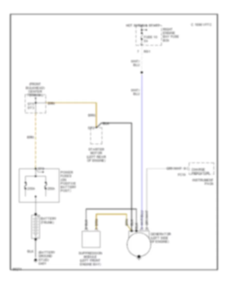
4.0L, Charging Wiring Diagram for Jaguar XJ6 L 1997
List of elements for 4.0L, Charging Wiring Diagram for Jaguar XJ6 L 1997:
- (battery ground stud) g401
- (front bulkhead) center terminal
- 1996 vftc c
- 250a
- Battery (trunk)
- Charge indicator
- Fc10
- Fuse 10 5a
- Generator (left side of engine)
- Hot in run & start
- Instrument pack
- Power fuses (on positive battery post)
- Right engine bay fuse box
- Rs1
- St2
- St5 st3
- St8
- Starter motor (left rear of engine)
- Suppression module (left front engine bay)
4.0L, Starting Wiring Diagram for Jaguar XJ6 L 1997
List of elements for 4.0L, Starting Wiring Diagram for Jaguar XJ6 L 1997:
- (battery ground stud) g401
- (left console ground stud) g206
- (not used)
- 1996 vftc c
- 250a
- Acc
- An1/ st4
- Arm/disarm
- Battery (trunk)
- Body processor module (passenger's underscuttle)
- Bt35
- Ca21
- Cc13
- Center terminal (front bulkhead)
- Chk engine
- Chk engine (mil)
- Data
- Decoder module (center console)
- Engine control module (right "a" post)
- Fc1
- Fc10
- Fc2
- Fc3
- Fuse 12 10a
- Fuse 3 25a
- Fuse 5 10a
- Generator (left side of engine)
- Gnd
- Hot at all times
- Hot in run & start
- Ignition switch
- Iii
- Input
- Instrument pack
- Left engine bay fuse box
- Left engine bay relays
- Ls1
- Nca
- Note: all vehicles require "check engine" signal input to body processor module before body processor module enables engine cranking
- Off
- Output
- P,n
- Pi104
- Pi105
- Power
- Power fuses (on positive battery post)
- Right engine bay fuse box
- Rotary switch
- Rs1
- Run
- Security & locking control module (left front of trunk)
- St1
- St2
- St5 st3
- St8
- Start
- Starter motor (left rear of engine)
- Starter relay
- Suppression module (left front engine bay)
- Trunk fuse box
SUPPLEMENTAL RESTRAINTS
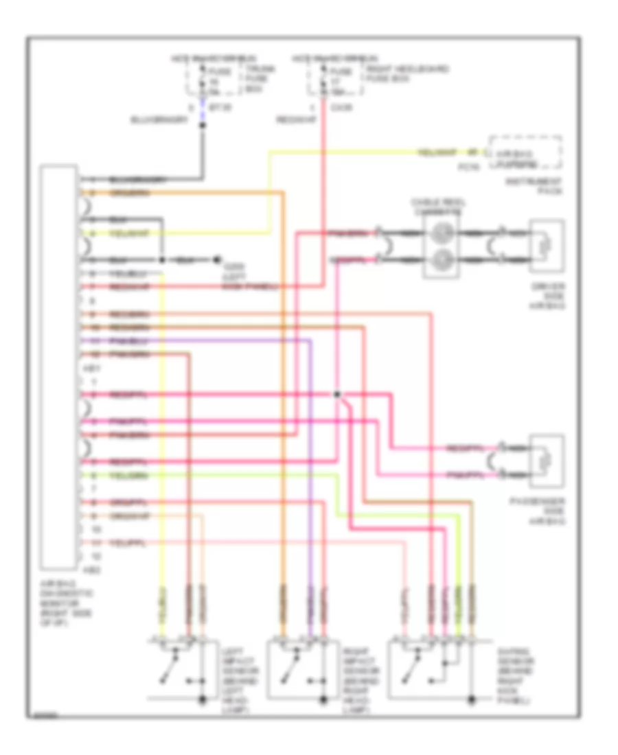
Supplemental Restraint Wiring Diagram for Jaguar XJ6 L 1997
List of elements for Supplemental Restraint Wiring Diagram for Jaguar XJ6 L 1997:
- Ab1
- Ab2
- Air bag diagnostic monitor (right side of i/p)
- Air bag warning
- Bt35
- Ca36
- Cable reel cassette
- Driver side air bag
- Fc10
- Fuse 15a
- Fuse 5a
- G200 (left kick panel)
- Hot in acc or run
- Instrument pack
- Left impact sensor (behind left head- lamp)
- Nca
- Passenger side air bag
- Right heelboard fuse box
- Right impact sensor (behind right head- lamp)
- Safing sensor (behind right kick panel)
- Trunk fuse box
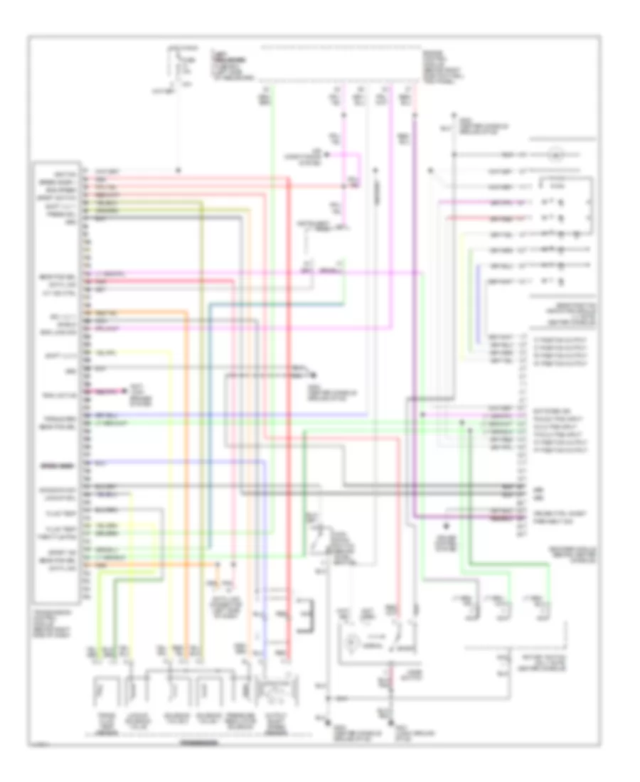
TRANSMISSION
A/T Wiring Diagram for Jaguar XJ6 L 1997
List of elements for A/T Wiring Diagram for Jaguar XJ6 L 1997:
- "2" position output
- "3" position output
- "d" position output
- "d,3,2" pos input
- "n" position output
- "p" position output
- "p,r,3,2" pos input
- "r" position output
- "r,n,d,3" pos input
- (not used)
- A/t ind ctrl
- Air conditioning system
- Anti- lock brakes system
- Ca1
- Cruise control system
- Cruise ctrl inhibit
- Data link
- Data link connector (left side of dash)
- Decoder module (behind center console)
- Eng load sig
- Eng speed
- Engine control module (behind right side footwell trim panel)
- Fluid temp
- Fuse 10a
- G302 (center console ground stud)
- G401 (logic ground stud)
- Gear pos sel
- Gear position indicator module ("j" gate, center console)
- Grd
- Hot in run
- Ignition
- Instrument pack
- Kick- down switch (behind accel- erator)
- Kickdown sw
- L l l l l
- Left left left heelboard heelboard heelboard fuse box (left side of heelboard)
- Lockup sol
- Lockup solenoid valve
- Mode switch
- Nca
- Normal
- Output shaft speed sensor
- Park/neut sig
- Pnk
- Press sol
- Pressure regulator solenoid
- Red
- Rotary switch (on 'j' gate, center console)
- Shield
- Shift vlv 1
- Shift vlv 2
- Sol vlv +
- Solenoid valve 1
- Solenoid valve 2
- Speed snsr +
- Speed snsr - speed snsr - speed snsr - speed snsr -
- Sport
- Sport ind
- Sport switch
- Switched ign
- Throttle pos
- Torque red
- Trac active
- Trans fluid temp sensor
- Transmission control module (behind right side of dash)
- Transmission transmission transmission
TRUNK, TAILGATE, FUEL DOOR
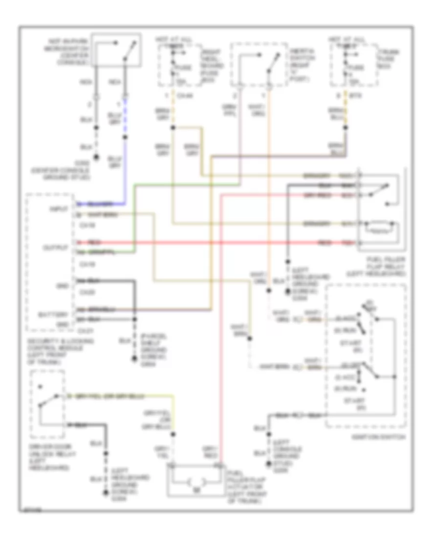
Fuel Door Release Wiring Diagram for Jaguar XJ6 L 1997
List of elements for Fuel Door Release Wiring Diagram for Jaguar XJ6 L 1997:
- (0) off
- (i) acc
- (ii) run
- (left console ground stud) g206
- (left heelboard ground screw) g304
- (parcel shelf ground screw) g904
- 10(5)
- 6(1)
- 7(2)
- 8(3)
- 9(4)
- Battery
- Bt9
- Ca18
- Ca19
- Ca20
- Ca21
- Ca44
- Driver door unlock relay (left heelboard)
- Fuel filler flap actuator (left front of trunk)
- Fuel filler flap relay (left heelboard)
- Fuse 10a
- Fuse 15a
- G302 (center console ground stud)
- Gnd
- Hot at all times
- Ignition switch
- Inertia switch (right "a" post)
- Input
- Nca
- Not-in-park microswitch (center console)
- Output
- Red
- Right heel- board fuse box
- Security & locking control module (left front of trunk)
- Start (iii)
- Trunk fuse box
Trunk Release Wiring Diagram for Jaguar XJ6 L 1997
List of elements for Trunk Release Wiring Diagram for Jaguar XJ6 L 1997:
- (0) off
- (i) acc
- (ii) run
- (iii) start
- (logic ground stud) g401
- (o) off
- (parcel shelf ground screw) g904
- Battery
- Bt35
- Bt9
- Ca18
- Ca19
- Ca20
- Ca21
- Fascia trunk release switch
- Fuse 10a
- Fuse 15a
- G206 (left console ground stud)
- G302 (center console ground stud)
- G405 (rear trunk ground stud)
- Gnd
- Hot at all times
- Ignition switch
- Inertia switch (right "a" post)
- Input
- Nca
- Not-in-park microswitch (center console)
- Output
- Security & locking control module (left front of trunk)
- Start (iii)
- Trunk fuse box
- Trunk release actuator (trunk lid)
- Trunk release relay (trunk electrical carrier)
- Trunk release switch
- Valet switch
WARNING SYSTEMS
Warning System Wiring Diagrams for Jaguar XJ6 L 1997
List of elements for Warning System Wiring Diagrams for Jaguar XJ6 L 1997:
- (center console ground stud) g302
- (left "a" post ground screw) g202
- (left console ground stud) g206
- (logic ground stud) g401
- 1996 vftc c
- 21d
- Audible warnings: driver door open (side lights on; key-in) key in ignition transmission not in park driver seat belt memory set direction indicators/ hazard
- Battery
- Body processor module (passengers underscuttle)
- Bt35
- Ca105
- Ca106
- Ca107
- Center console switch pack
- Column switchgear (steering column)
- Direction indicator switches
- Driver door switch (driver's door)
- Driver door switch pack (arm rest)
- Driver seat control module (driver's seat)
- Fc1
- Fc10
- Fc2
- Fc3
- Fc4
- Fc8
- Fuse 10a
- Gnd
- Hazard
- Hot at all times
- Ignition switch
- Input
- Instrument pack
- Key- in
- Left
- Lighting switches
- Nca
- Not in-park microswitch (center console)
- Output
- Passenger seat control module (passenger's seat)
- Right
- Sc3
- Seat belt switch (under driver's seat)
- Seat belt warning
- Seat ground stud) g300
- Side lamps
- Sm1
- Sm6
- Speaker
- Trunk fuse box
- Vehicle speed output
WIPER/WASHER
Wiper/Washer Wiring Diagram for Jaguar XJ6 L 1997
List of elements for Wiper/Washer Wiring Diagram for Jaguar XJ6 L 1997:
- (left bulkhead ground stud) g116
- (left console ground stud) g206
- (left forward ground stud) g100
- (not used)
- (right bulkhead ground stud) g123
- (right forward ground stud) g107
- Ambient temperature switch (left front wheel arch liner, near spoiler tray)
- Battery
- Body processor module (passenger's underscuttle)
- Bt35
- Ca36
- Column switch gear
- Console ground stud) g206
- Delay
- Fast
- Fc1
- Fc12
- Fc2
- Fc3
- Fc58
- Fc61
- Fc8
- Fuse 10 5a
- Fuse 13 10a
- Fuse 16 10a
- Fuse 17 30a
- Fuse 5 10a
- Fuse 6 20a
- Ground
- Headlamp power wash pump relay (right engine bay relays)
- Hot at all times
- Hot in run & start
- Input
- Instrument cluster system
- Left engine bay fuse box
- Left windshield wash heater (plenum chamber, behind cover)
- Lighting switches (fascia switch pack)
- Ls37
- Ouput
- Output
- Park switch
- Power distribution system
- Power wash pump (engine bay, right inner fender)
- Red
- Right engine bay fuse box
- Right heelboard fuse box
- Right windshield wash heater (plenum chamber, behind cover)
- Rs1
- Rs6
- Sc2
- Side lamps
- Slow
- Slow/ flick
- Trunk fuse box
- Wash
- Wash/wipe switch diode (fascia harness, behind passenger side airbag, passenger side fascia trim)
- Wash/wipe switches
- Washer fluid level switch (washer fluid reservoir)
- Windshield wash pump (washer fluid reservoir)
- Windshield wash pump relay (right engine bay relays)
- Wiper fast/ slow relay (left engine bay relays)
- Wiper motor (plenum chamber, behind cover)
- Wiper on/ off relay (left engine bay relays)

 Čeština
 Dansk
Dansk Deutsch
 Ελληνικά
 English
 English
 Español
 Suomi
Suomi Français
 Français
 עברית
עברית Hrvatski
 Magyar
 Italiano
 日本語
日本語 한국어
한국어 Nederlands
 Polski
 Português
 Português
 Русский
 Slovenčina
 Slovenščina
 Svenska
 Türkçe
 中文 (中国)