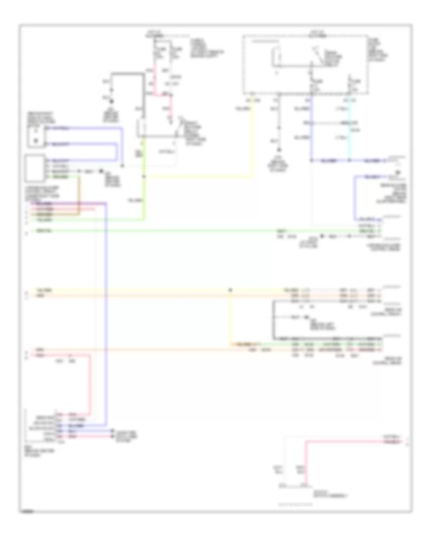
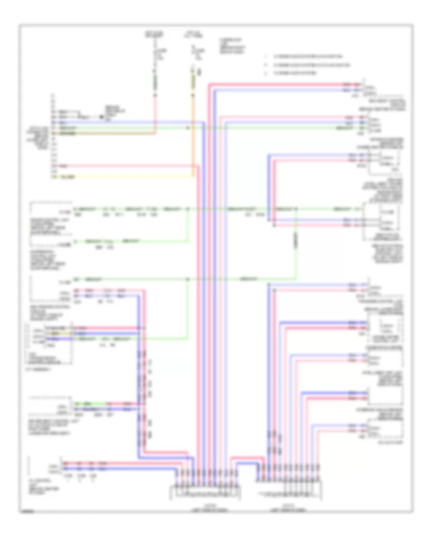
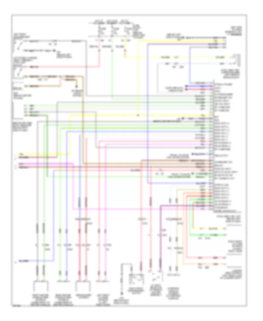
AIR CONDITIONING
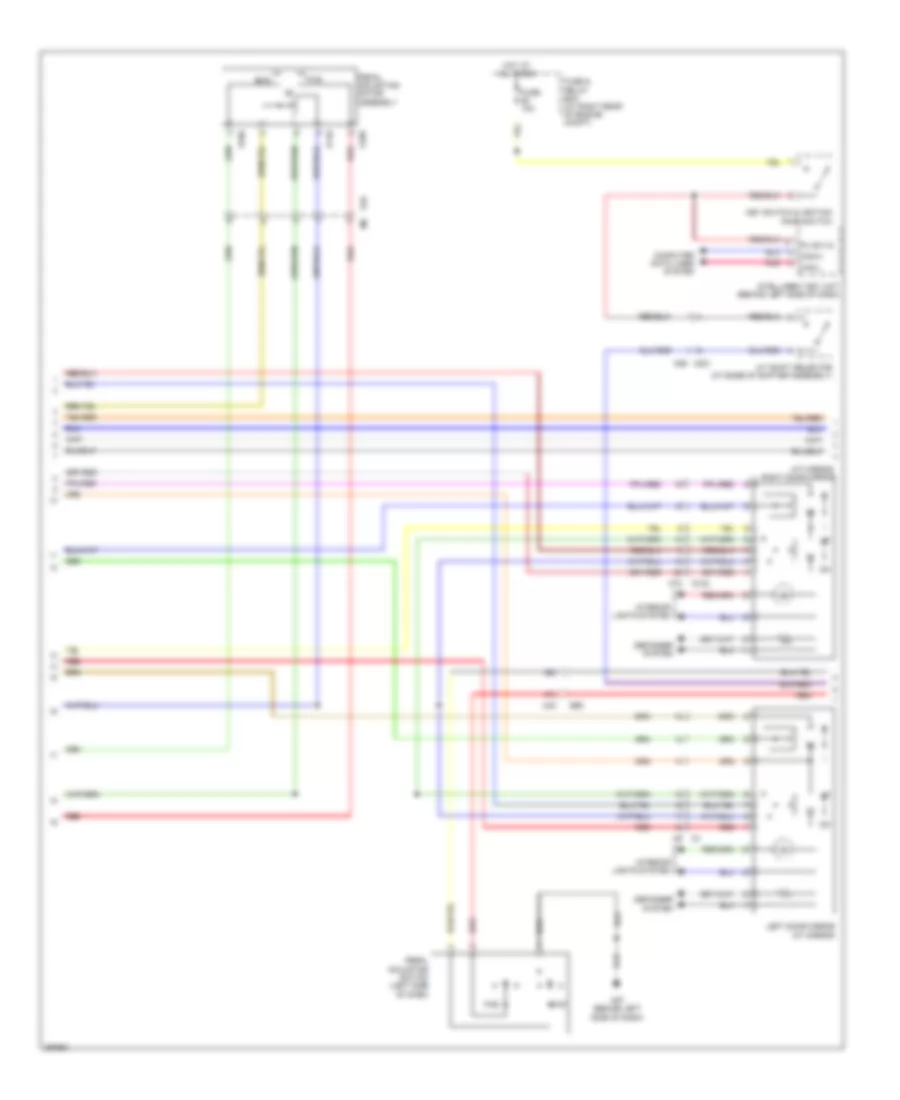
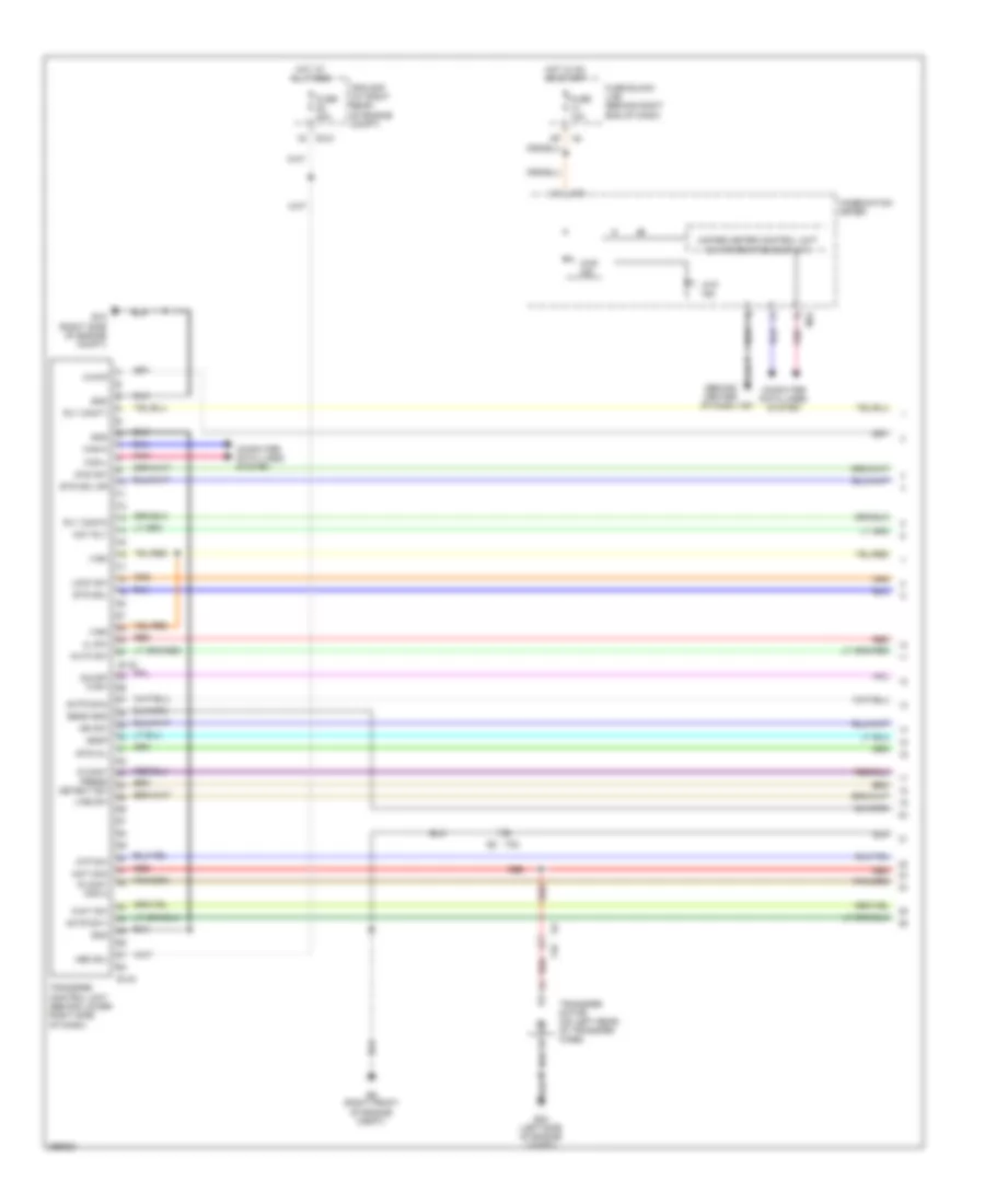
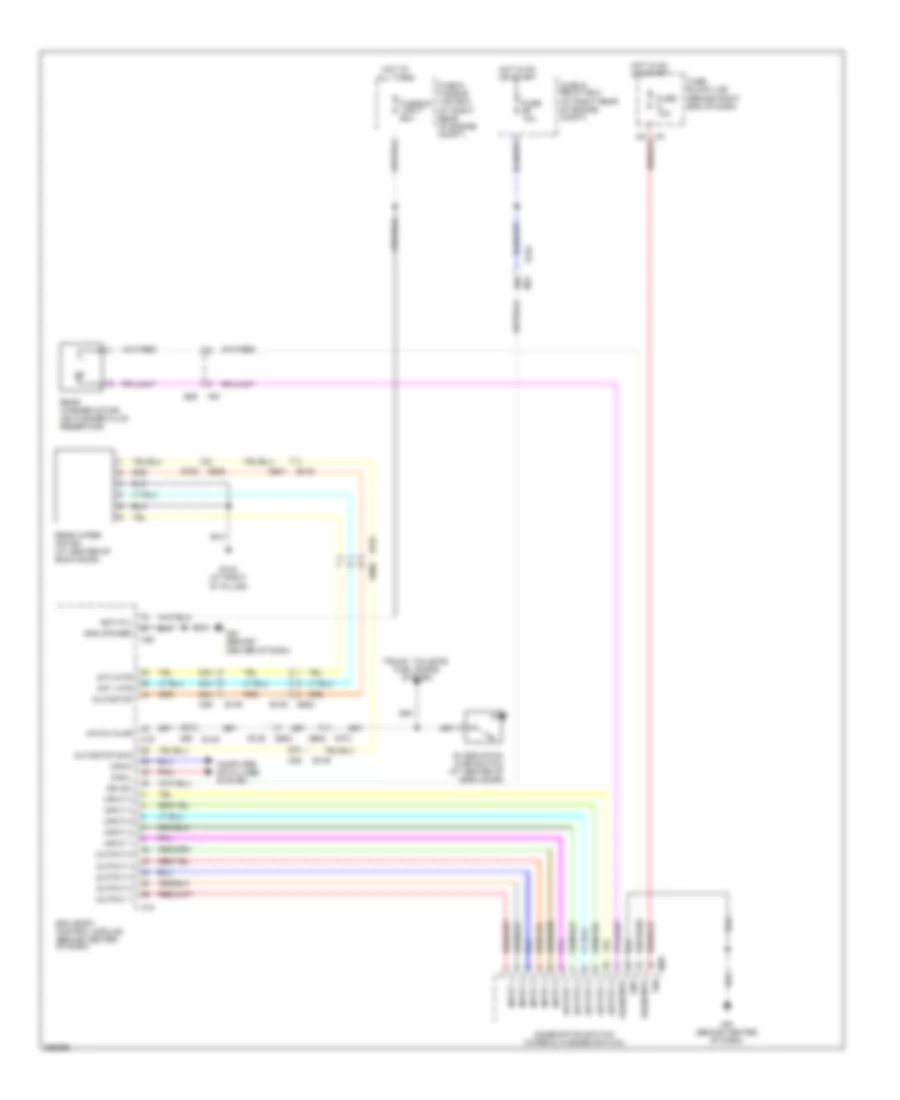
Automatic A/C Wiring Diagram (1 of 3) for Nissan Armada SL 2013
 https://portal-diagnostov.com/license.html
Automotive Electricians Portal FZCO
Automotive Electricians Portal FZCO
https://portal-diagnostov.com/license.html
https://portal-diagnostov.com/license.html
Automotive Electricians Portal FZCO
Automotive Electricians Portal FZCO
List of elements for Automatic A/C Wiring Diagram (1 of 3) for Nissan Armada SL 2013:
- 34g
- 35g
- 38a
- 4q m39
- 59g
- 5n m3
- 61g
- 76a
- 78a
- 79a
- 81a
- 86a
- 87a
- 88a
- 89a
- 90a
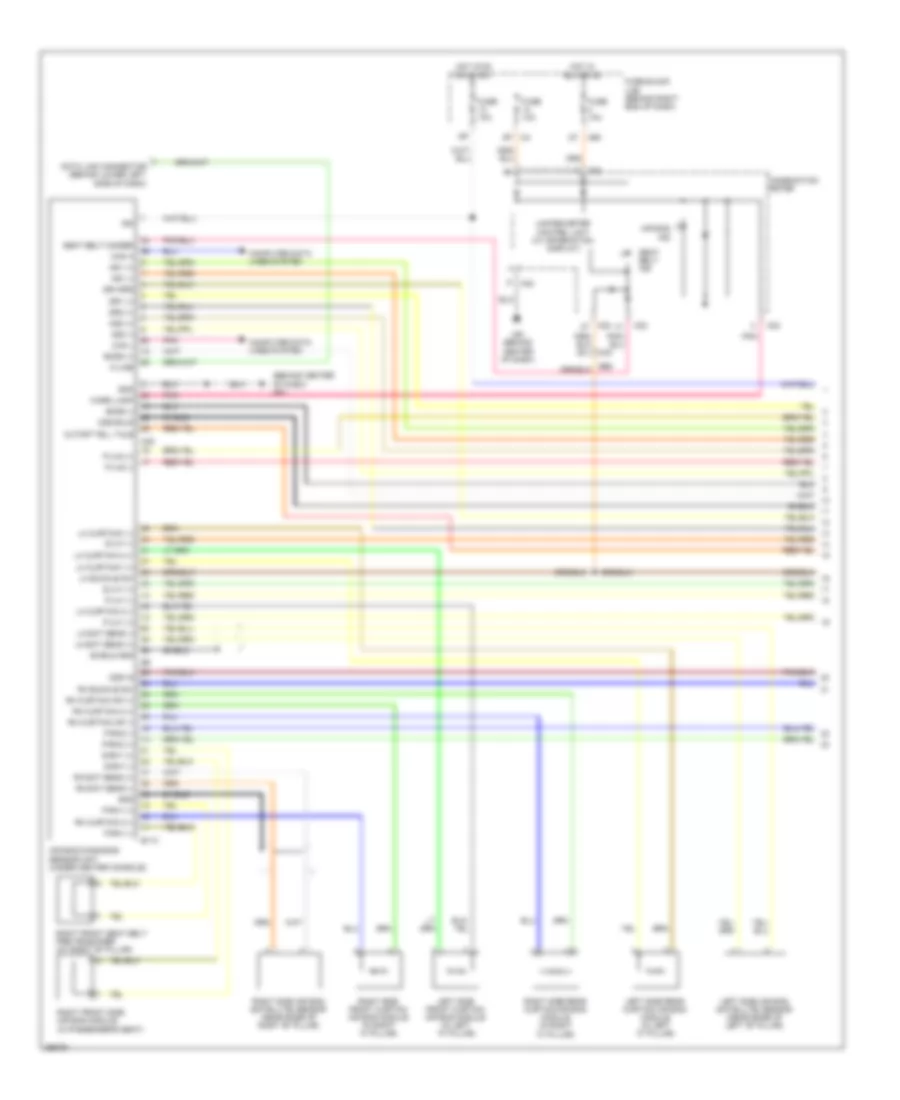
- A/c auto amp
- Ac request
- Amb temp sens
- Ambient sensor (center front of engine compt)
- Aux mode a
- Aux mode b
- Aux mode feedback
- Aux temp a
- Aux temp b
- Aux temp feedback
- Aux vbc
- B149
- Can-h
- Can-l
- Computer data lines system
- Defroster door motor (behind center of dash)
- Driver air mix door motor (behind right side of dash)
- E152
- Evap air temp sens
- F14
- Fan on
- Floor dr a
- Floor dr b
- Floor feedback
- Fr lin bus
- Fr vbc
- Front mode door motor (behind lower center of dash)
- Fuse 10a
- Fuse block (j/b) (behind right end of dash)
- Gnd
- Hot at all times
- Hot in on or start
- Ign
- Ill+
- Ill-
- In-vehicle sensor (behind lower center of dash)
- Incar mtr+
- Incar temp sen
- Intake door motor (behind right side of dash)
- Intake sensor (behind right side of dash)
- Interior lights system
- J/c m02
- M301
- M31
- M36
- M36 b149
- M49
- M50
- M57 (behind left side of dash)
- M61 (behind center of dash)
- M65
- Optical sensor (top center of dash)
- Panel defrost door a
- Panel defrost door b
- Panel defrost feedback
- Passenger air mix door motor (behind right side of dash)
- Pnk
- Rear air mix door motor (behind right rear quarterpanel)
- Rear mode door motor (behind right rear quarterpanel)
- Recirc door a
- Recirc door b
- Rr lin bus
- Sensor return
- Sunload sen left (dr)
- Sunload sen right(pass)
- Temp door a fr lh
- Temp door a fr rh
- Temp door b fr lh
- Temp door b fr rh
- Temp door feedback fr lh
- Temp dr feedback fr rh
- V ref actr (5v)
- V ref return (gnd)
- Water valve (rear of engine compt)
- Water valve close a
- Water valve open b
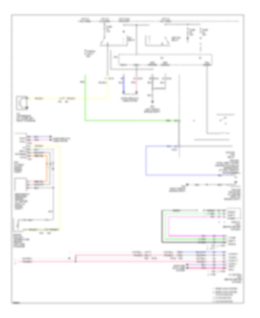
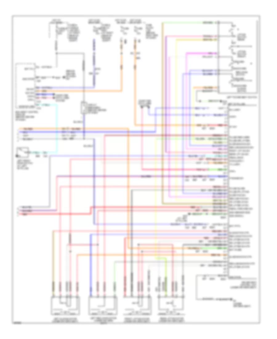
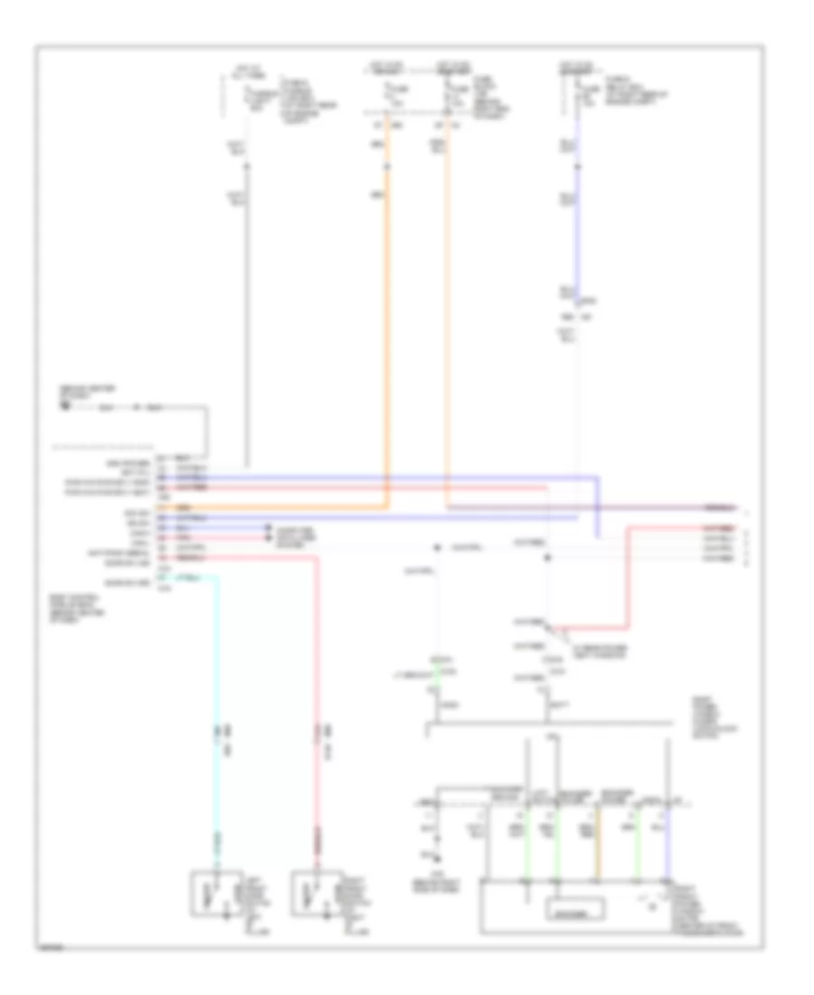
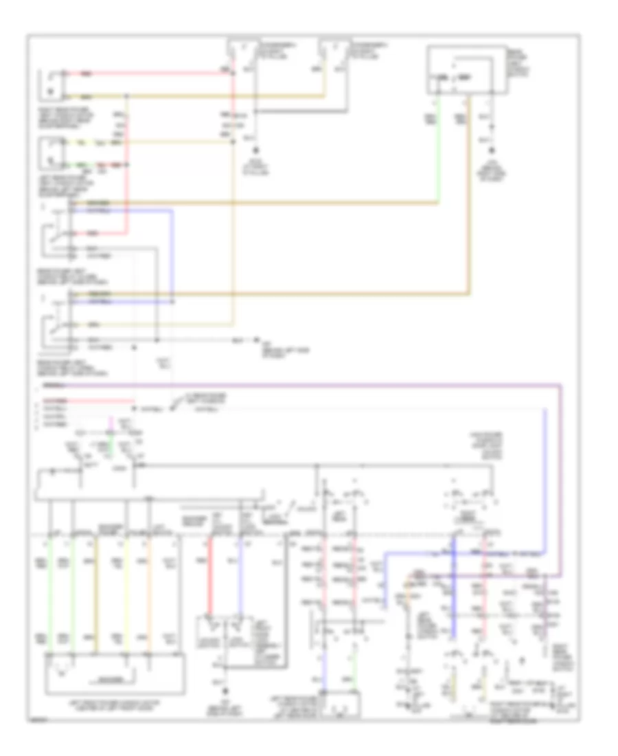
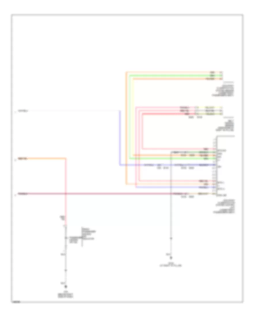
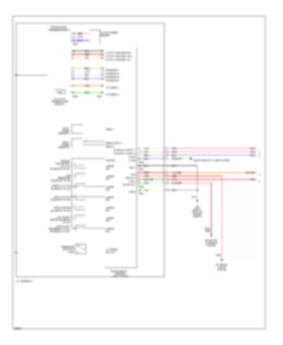
Automatic A/C Wiring Diagram (2 of 3) for Nissan Armada SL 2013
List of elements for Automatic A/C Wiring Diagram (2 of 3) for Nissan Armada SL 2013:
- (behind right side of dash)
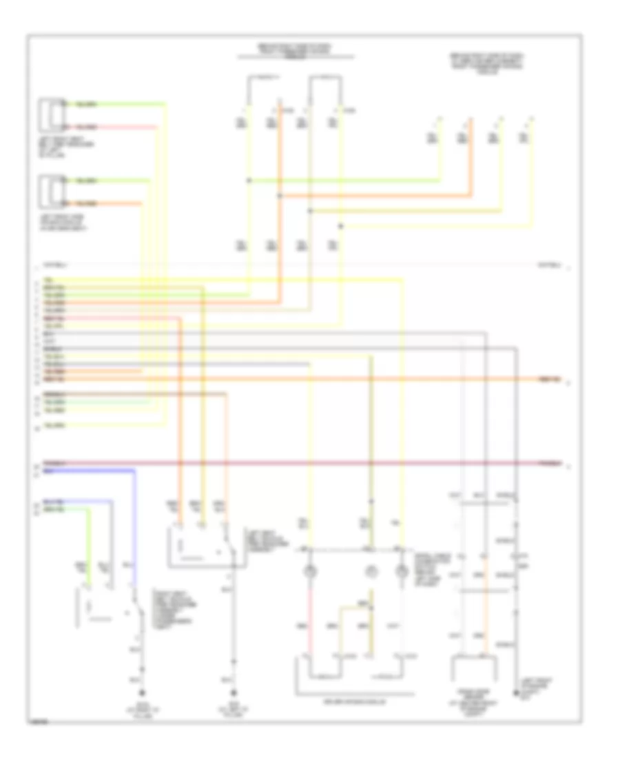
- (behind right side of dash) front blower motor
- 35a
- 36a
- 37a
- 4g m31
- 99a
- Ac & av switch assembly
- Air con sw
- B132 (at right "d" pillar)
- B146
- B149
- Bcm (behind center of dash)
- Blwr fan sw
- Can-h
- Can-l
- Computer data lines system
- E152
- Front blower relay (under right side of dash)
- Fuse & fusible link box (at right rear of engine compt)
- Fuse 15a
- Fuse 20a
- Fuse block (j/b) (behind right end of dash)
- Hot at all times
- M18
- M3 3n
- M301
- M36
- M36 98a
- M39 3q
- M57 (behind left side of dash)
- M61 (behind center of dash)
- M65
- M79
- Pnk
- R101
- R201
- Rear air control (front)
- Rear air control (rear)
- Rear blower motor (behind right rear quarterpanel)
- Rear blower motor relay
- Sens gnd
- Variable blower control (front) (under right side of dash)
- Variable blower control (rear)
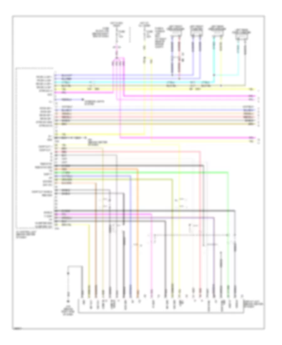
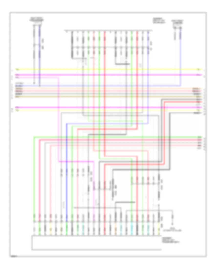
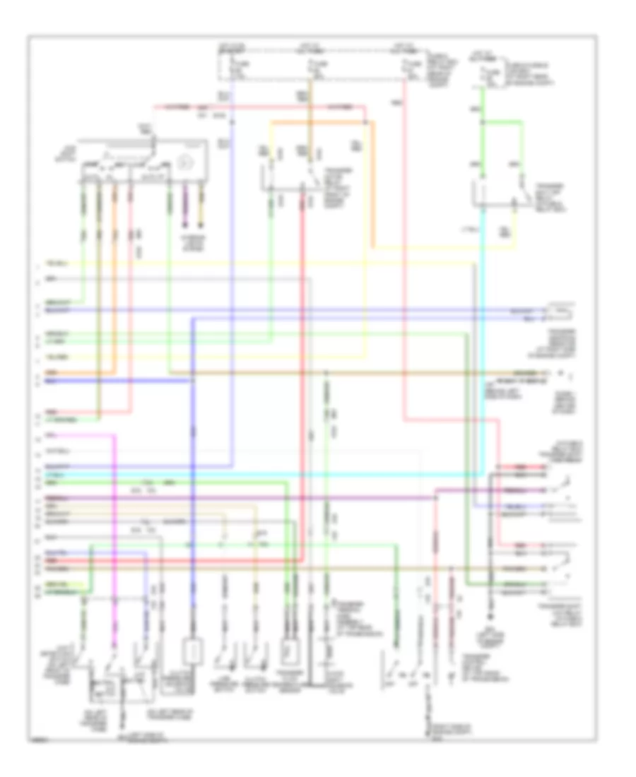
Automatic A/C Wiring Diagram (3 of 3) for Nissan Armada SL 2013
List of elements for Automatic A/C Wiring Diagram (3 of 3) for Nissan Armada SL 2013:
- (left side of engine compt)
- 18a
- 23a
- 24a
- 28a
- A/c compressor (at lower left front of engine)
- A/c relay
- Av control unit (behind center of dash)
- Avcc
- B149
- Base audio system
- Bose audio system
- Can-h
- Can-l
- Computer data lines system
- Cooling fan motor (at center front of engine compt)
- Cooling fan relay
- Cpu
- Disp it
- Disp-it
- Display unit (behind center of dash)
- E119
- E120
- E122
- E124
- E15 (right side of engine compt)
- E16
- E24
- Ecm (at right side of engine compt)
- Engine coolant temperature sensor (left side of engine)
- F14 e5
- F201
- F26
- F32
- F54
- Fan motor
- Fuse 10a
- Fuse 20a
- Fusible link n 25a
- Gnd (power)
- Gnd (signal)
- Gnd a
- Hot at all times
- Hot in on or start
- Ig+
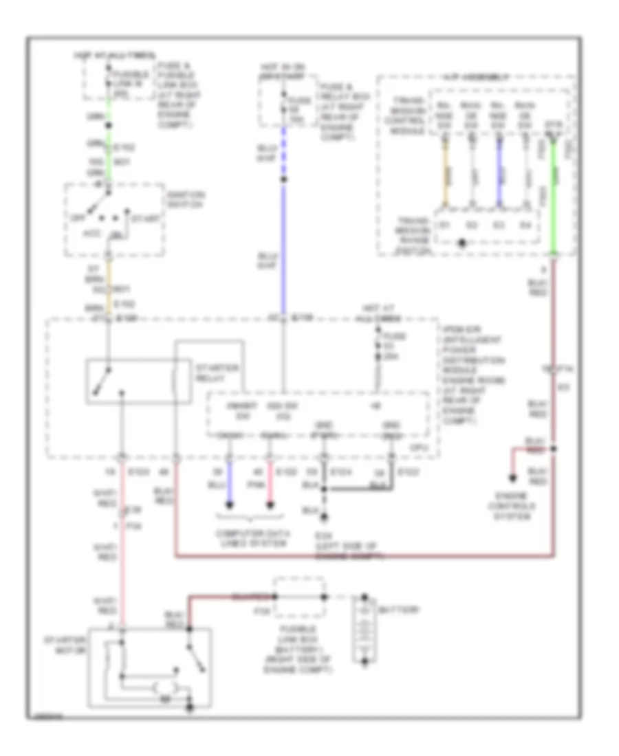
- Ignition relay
- Ipdm e/r (intelligent power distribution module engine room) (at right rear of engine compt)
- It disp
- It-disp
- M can1 h
- M can1 l
- M can2 h
- M can2 l
- M162
- M165
- M166
- M171
- M36
- M44
- M46
- Pd press
- Pnk
- Refrigerant pressure sensor (at center front of engine compt)
- Shield
- W/ navigation
- W/o navigation
ANTI-LOCK BRAKES
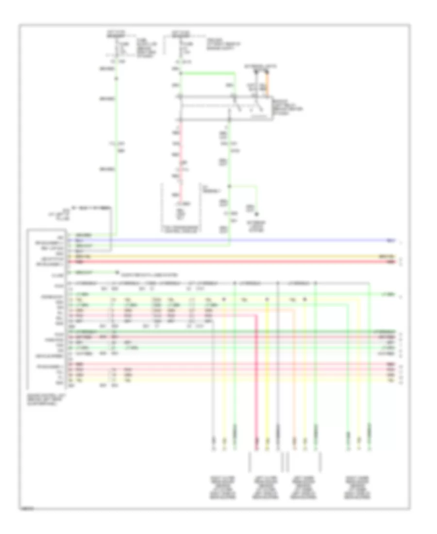
Anti-lock Brakes Wiring Diagram (1 of 2) for Nissan Armada SL 2013
List of elements for Anti-lock Brakes Wiring Diagram (1 of 2) for Nissan Armada SL 2013:
- (on left side of engine compt) abs actuator & electric unit (control unit)
- 12c
- 13c
- 30c
- 31c
- 51g
- Abs/tcs/vdc control unit
- Bls
- Brl-out
- Bst gnd
- Bst nc
- Bst no
- Bst sig
- Can-h
- Can-l
- Can2-h
- Can2-l
- Clstr gnd
- Computer data lines system
- Data link connector (behind lower left side of dash)
- Del s gnd
- Del s sig
- Diag-k
- E119
- E126 (left front of engine compt)
- E26
- E41
- Exterior lights systems
- Fl in sol
- Fl level sw
- Fl out sol
- Fr in sol
- Fr out sol
- Front pressure sensor (at left side of engine compt)
- Fuse 10a
- Fuse block (j/b) (behind right end of dash)
- Gnd
- Hot at all times
- Hot in on or start
- Hsv1 mc1
- Hsv2 mc2
- Ign
- Ipdm e/r (intelligent power distribution module engine room) (at right rear of engine compt)
- Left front wheel sensor (at left front steering knuckle assembly)
- Left rear wheel sensor (at left rear wheel hub assembly)
- M31 e152
- M60
- M91
- Mot (+)
- Mot (-)
- Mtr gnd
- Mtr sply
- Pnk
- Ps1 gnd
- Ps1 sig
- Ps2 gnd
- Ps2 sig
- Pwr
- Rear pressure sensor (at left side of engine compt)
- Right front wheel sensor (at right front steering knuckle assembly)
- Right rear wheel sensor (at right rear wheel hub assembly)
- Rl in sol
- Rl out sol
- Rr in sol
- Rr out sol
- Sig
- Solenoid valve
- Stop lamp relay (in fuse & relay box)
- Stop lamp switch (attached to brake pedal assembly)
- Usv1 mc1
- Usv2 mc2
- Vdc off sw
- Vlv ecu gnd
- Vlv ecu sply
- Wss fl pwr
- Wss fl sig
- Wss fr pwr
- Wss fr sig
- Wss rl pwr
- Wss rl sig
- Wss rr pwr
- Wss rr sig
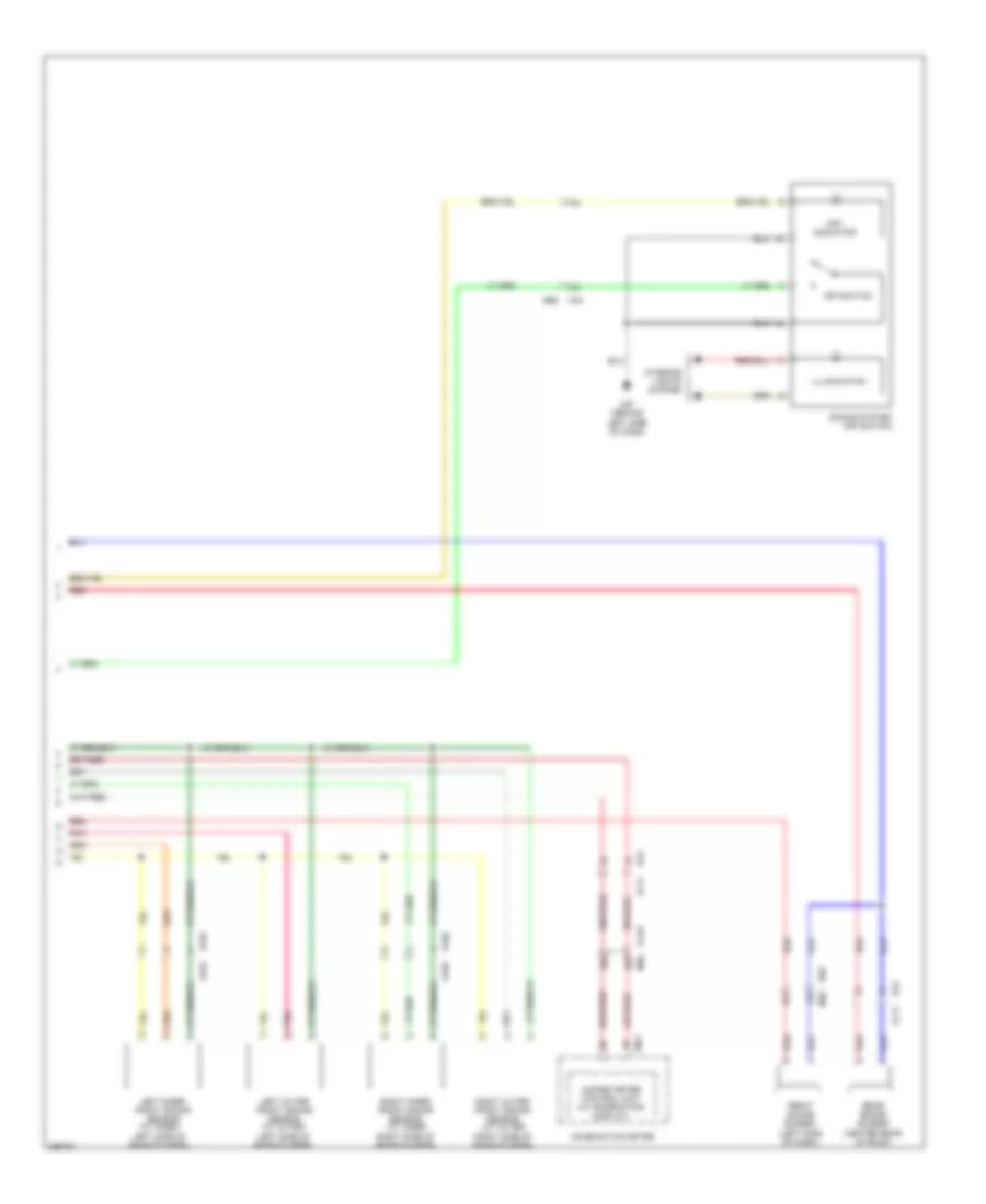
Anti-lock Brakes Wiring Diagram (2 of 2) for Nissan Armada SL 2013
List of elements for Anti-lock Brakes Wiring Diagram (2 of 2) for Nissan Armada SL 2013:
- (w/ information display)
- 45g m31
- Abs ind
- Active booster (at left rear corner of engine compt)
- Brake fluid level switch (on brake fluid reservoir)
- Brake ind
- Can-h
- Can-l
- Clu gnd
- Clu p
- Combination meter
- Computer data lines system
- Dels gnd
- Dels pwr
- Dels sig
- Delta stroke sensor (at left side of engine compt)
- E15 (right side of engine compt)
- E152
- E26
- Fuse & fusible link box (at right rear of engine compt)
- Fuse 10a
- Fuse block (j/b) (behind right end of dash)
- Fusible link h 30a
- Fusible link i 40a
- Gnd
- Hot at all times
- Hot in on or start
- Interior lights system
- M251
- M61 (behind center of dash)
- M63
- M79 (behind right side of dash)
- M91
- Parking brake switch (at base of park brake lever)
- Pnk
- Pwr
- Slip ind
- Steering angle sensor (behind left side of dash)
- Unified meter control unit
- Vdc off ind
- Vdc off switch
- Yaw rate/side/decel g sensor (under center console)
ANTI-THEFT
Forced Entry Wiring Diagram (1 of 2) for Nissan Armada SL 2013
List of elements for Forced Entry Wiring Diagram (1 of 2) for Nissan Armada SL 2013:
- 15a
- 25a
- 26a
- 30j
- 4q m39
- 6t m60
- Acc sw
- Anti-pinch serial link
- B111
- B149
- B19 (at left "d" pillar)
- B43
- B48
- B69
- Back door latch (door ajar switch) (at bottom center of back door)
- Back door sw
- Back door switch (at bottom center of back door)
- Bat
- Bat (f/l)
- Bcm (body control module) (behind center of dash)
- Can-h
- Can-l
- Closed
- Combination meter
- Computer data lines system
- D401
- D405
- D501
- D602
- D606
- D701
- Door sw (as)
- Door sw (dr)
- Door sw (rl)
- Door sw (rr)
- Fuse & fusible link box (at right rear of engine compt)
- Fuse 10a
- Fuse 15a
- Fuse block (j/b) (behind right end of dash)
- Fusible link f 50a
- Glass hatch ajar
- Glass hatch ajar switch (at center of back door)
- Gnd (power)
- Hot at all times
- Hot in acc or on
- Left front door switch (at left "b" pillar)
- Left rear door switch (at left "c" pillar)
- M18
- M19
- M20
- M3 1n
- M36
- M36 21a
- M40 21j
- M61 (behind center of dash)
- Open
- Pnk
- Right front door switch (at right "b" pillar)
- Right rear door switch (at right "c" pillar)
- Security ind
- Security ind output
- Trunk, tailgate & fuel doors system
- W/ power back door
- W/o power back door
Forced Entry Wiring Diagram (2 of 2) for Nissan Armada SL 2013
List of elements for Forced Entry Wiring Diagram (2 of 2) for Nissan Armada SL 2013:
- (behind left side of dash) m57
- (in fuse & relay box) daytime light relay
- +ig
- Anti pinch serial link
- Between full stroke & n
- Can-h
- Can-l
- Computer data lines system
- Cpu
- D101
- D102
- E122
- E123
- E124
- E15 (right side of engine compt)
- E24 (left side of engine compt)
- Full stroke
- Fuse & fusible link box (at right rear of engine compt)
- Fuse 10a
- Fuse 15a
- Fuse 20a
- Gnd
- Gnd (power)
- Gnd (signal)
- H/lp hi
- H/lp lo
- H/lp lo rh
- Headlamp low relay
- High beam
- Horn (at right front of engine compt)
- Horn relay (in fuse & fusible link box)
- Horn rly
- Horns system
- Hot at all times
- Hot in on or start
- Ignition relay
- Ipdm e/r (intelligent power distribution module engine room) (at right rear of engine compt)
- Key cyl lock sw
- Key cyl unlock switch
- Left front combination lamp
- Left front door lock assembly (key cylinder switch) (rear of driver's door)
- Left headlamp high relay
- Lock
- Lock switch
- Low beam
- M74
- M79 (behind right side of dash)
- Main power window & door lock/ unlock switch
- Pnk
- Red
- Right front combination lamp
- Right power window & door lock/unlock switch
- Unlock
- Unlock switch full stroke
- W/ drl
- W/o drl
Immobilizer Wiring Diagram for Nissan Armada SL 2013
List of elements for Immobilizer Wiring Diagram for Nissan Armada SL 2013:
- +ig
- 13p
- 21g
- 99g m31
- Bat (f/l)
- Bat (fuse)
- Bcm (body control module) (behind center of dash)
- Can-h
- Can-l
- Combination meter
- Computer data lines system
- Cpu
- E121
- E122
- E124
- E15 (right side of engine compt)
- E152
- E16
- E24 (left side of engine compt)
- Engine control module (ecm) (at right side of engine compt)
- Fuse & fusible link box (at right rear of engine compt)
- Fuse & relay box (at right rear of engine compt)
- Fuse 10a
- Fuse 15a
- Fuse 20a
- Fuse block (j/b) (behind right end of dash)
- Fusible link f 50a
- Gnd (power)
- Gnd (signal)
- H/lp hi
- H/lp lo
- Headlights system
- Horn (at right front of engine compt)
- Horn relay (in fuse & fusible link box)
- Horn rly
- Horns system
- Hot at all times
- Hot in on or start
- Ign sw
- Ignition relay
- Immob antenna sig (clock)
- Immob antenna sig (rx,tx)
- Ipdm e/r (intelligent power distribution module engine room) (at right rear of engine compt)
- M18
- M20
- M61 (behind center of dash)
- Nats antenna amplifier (left side of dash)
- Pnk
- Security ind
- Security indicator output
BODY CONTROL MODULES
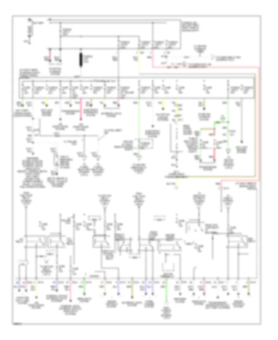
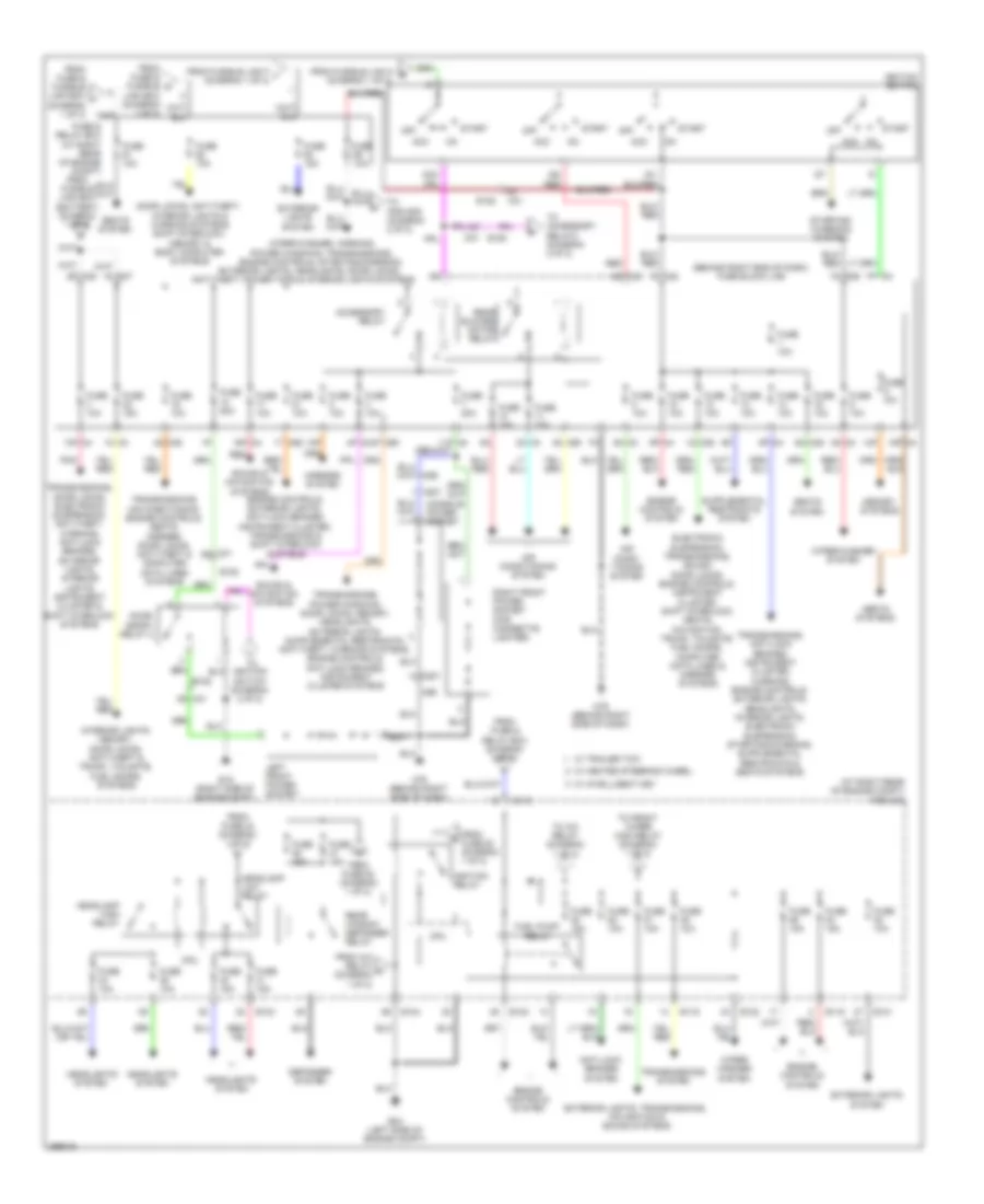
Body Control Modules Wiring Diagram for Nissan Armada SL 2013
List of elements for Body Control Modules Wiring Diagram for Nissan Armada SL 2013:
- 1n m3
- 6t m60
- Acc sw
- Air conditioning system
- Aircon sw
- Anti-pnch srl lnk
- Anti-theft system
- Auto l in
- Auto stop
- Auto stop 2
- Back door sw
- Bat (fuse)
- Bat saver output
- Batt
- Bcm (behind center of dash)
- Blower fan sw
- Brake sw
- Can-h
- Can-l
- Comb sw in 1
- Comb sw in 2
- Comb sw in 3
- Comb sw in 4
- Comb sw in 5
- Comb sw out 1
- Comb sw out 2
- Comb sw out 3
- Comb sw out 4
- Comb sw out 5
- Computer data lines system
- Defogger system
- Door locks system
- Door sw (as)
- Door sw (dr)
- Door sw (rl)
- Door sw (rr)
- Door unlock out (other)
- Dr lck out (all)
- Dr unlck out (dr)
- E152 99g
- Exterior lights & door locks systems
- Exterior lights system
- Flasher out lt
- Flasher out rt
- Fuse & fusible link box (at right rear of engine compt)
- Fuse & relay box (at right rear of engine compt)
- Fuse 10a
- Fuse 15a
- Fuse block (j/b) (behind right end of dash)
- Fusible link f 50a
- Gnd (pwr)
- Hatch ajar sw
- Hazard sw
- Headlights & exterior lights systems
- Headlights system
- Hot at all times
- Hot in acc or on
- Hot in on or start
- Ign sw
- Immb ant sig (ck)
- Immb ant sig (r,t)
- Interior lights & trunk, tailgate, fuel doors systems
- Interior lights system
- Ivcs input
- Key ring out
- Key sw
- Keyless pwr tuner
- Luggage lamp
- M18
- M19
- M20
- M31
- M61 (behind center of dash)
- Pnk
- Power tops & power windows systems
- Power windows & trunk, tailgate, fuel doors systems
- Pwr win pwr supp (rap)
- Red
- Room lamp output
- Rr defogger sw
- Rr win pwr supp (bat)
- Rr wip o/p 1 mtr
- Rr wip o/p 2 mtr
- Sec ind out
- Sig gnd
- Signal
- Step lamp output
- Tpms
- Trailer lt flshr
- Trailer rt flshr
- Trunk, tailgate, fuel door system
- Warning systems
- Wiper/washer system
COMPUTER DATA LINES
Computer Data Lines Wiring Diagram for Nissan Armada SL 2013
List of elements for Computer Data Lines Wiring Diagram for Nissan Armada SL 2013:
- (behind center of dash) m61
- 11j
- 14j
- 19a
- 22j
- 31g
- 32g
- 51g
- A/c auto amp
- A/t assembly
- Abs actuator & electric unit (control unit) (on left side of engine compt)
- Abs/tcs/vdc control unit
- Air bag diagnosis sensor unit (under center console)
- Av control unit (behind center of dash)
- B111
- B149
- B200
- B202
- B37
- B43
- B56
- B69
- Bcm (body control module) (behind center of dash)
- Can-h
- Can-l
- Combination meter
- Cpu
- Data link connector (behind lower left side of dash)
- Driver seat control unit (w/ automatic drive positioner (under driver's seat)
- E122
- E142
- E152
- E16
- E34 b40
- Ecm (engine control module) (at right side of engine compt)
- F14
- F14 e5
- F502
- Fuse 10a
- Fuse block (j/b) (behind right end of dash)
- Hot at all times
- Hot in on or start
- Intelligent key unit (if equipped) (behind left side of dash)
- Ipdm e/r (intelligent power distribution module engine room) (at right rear of engine compt)
- J/c m10 (left side of dash)
- J/c m11 (left side of dash)
- K-line
- M165
- M166
- M18
- M24
- M31
- M35
- M36
- M39
- M40
- M46
- M50
- Pnk
- Sonar control unit (if equipped) (behind left rear quarterpanel)
- Steering angle sensor (behind left side of dash)
- Suspension control unit (if equipped) (behind left rear quarterpanel)
- Tcm (transmission control module
- Transfer control unit (4wd) (behind lower right side of dash)
- Unified meter control unit
- W/ base audio system
- W/ bose audio system & navigation
- W/ bose audio system & w/o navigation
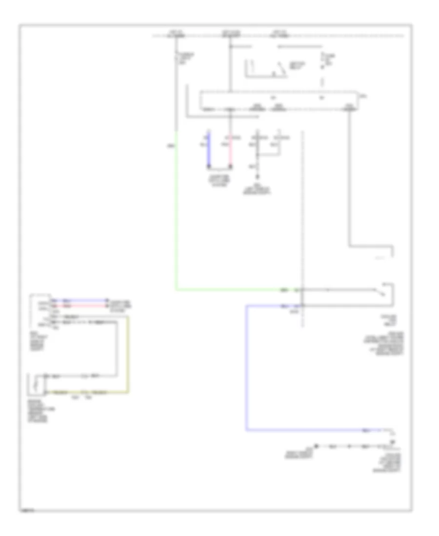
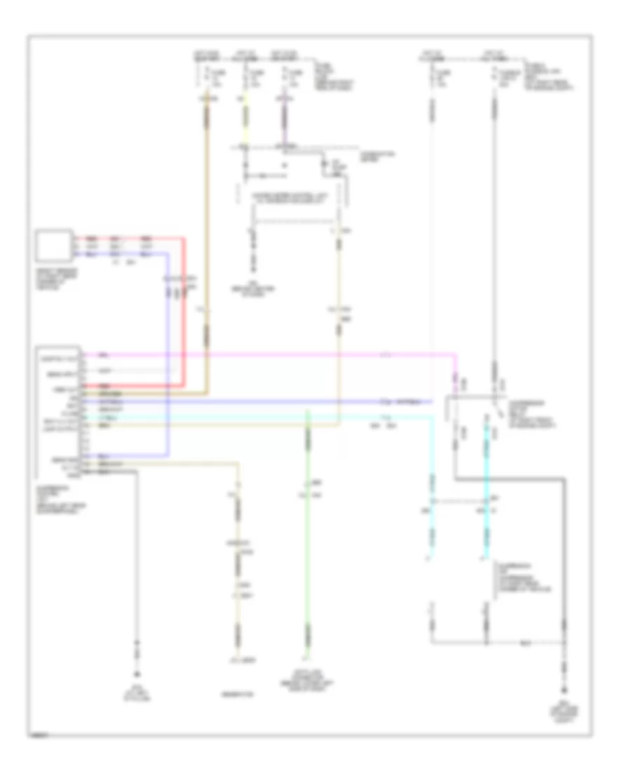
COOLING FAN
Cooling Fan Wiring Diagram for Nissan Armada SL 2013
List of elements for Cooling Fan Wiring Diagram for Nissan Armada SL 2013:
- Can-h
- Can-l
- Computer data lines system
- Cooling fan motor (at center front of engine compt)
- Cooling fan relay
- Cpu
- E120
- E122
- E124
- E15 (right side of engine compt)
- E16
- E24 (left side of engine compt)
- Ecm (at right side of engine compt)
- Engine coolant temperature sensor (left side of engine)
- F201
- F26
- F54
- Fan motor
- Fuse 20a
- Fusible link n 25a
- Gnd (power)
- Gnd (signal)
- Gnd a
- Hot at all times
- Hot in on or start
- Ig+
- Ignition relay
- Ipdm e/r (intelligent power distribution module engine room) (at right rear of engine compt)
- Pnk
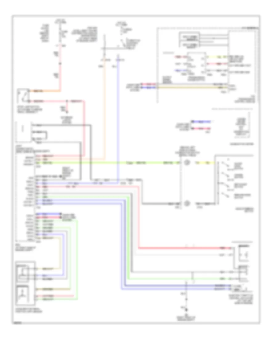
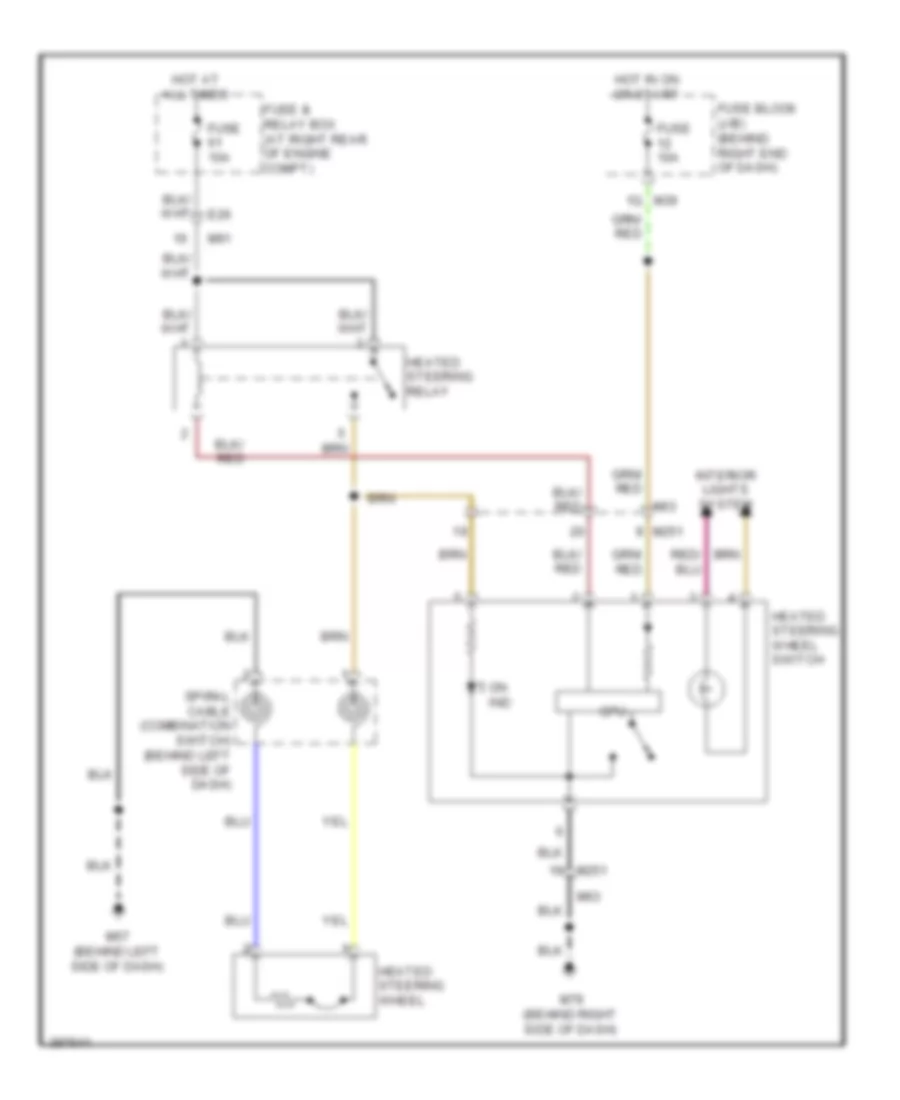
CRUISE CONTROL
Cruise Control Wiring Diagram for Nissan Armada SL 2013
List of elements for Cruise Control Wiring Diagram for Nissan Armada SL 2013:
- (behind left side of dash) combination switch (spiral cable)
- (right front of engine compt) e9
- 68g
- 69g
- A/t assembly
- Accelerator pedal position (app) sensor
- Aps1
- Aps2
- Ascd steering switch
- Ascdsw
- Avcc
- Avcc2
- Brake
- C1 (vin)
- C2 (vout)
- C3 (gnd) f506
- Can-h
- Can-l
- Cancel switch
- Close
- Combination meter
- Computer data lines system
- E119
- E122
- E152
- E16
- E9 (right front of engine compt)
- Ecm (at right side of engine compt)
- Electric throttle control actuator (at top left side of engine)
- Exterior lights system
- F14
- F32
- F502
- F503
- F505
- F54
- Fuse 10a
- Fuse 52 20a
- Fuse block (j/b) (behind right end of dash)
- Gnd
- Gnd-a
- Gnd-a2
- Hot at all times
- Input speed sensor 1
- Input speed sensor 2
- Ipdm e/r (intelligent power distribution module engine room) (at right rear of engine compt)
- Joint connector f01 (right side of engine compt)
- M102
- M24
- M30
- M31
- M60
- Motor 1
- Motor 2
- Motrly
- On/off (main) switch
- Open
- Out spd sen gnd
- Out spd sen vout
- Output speed sensor
- Pnk
- Red
- Resume/accel switch
- Rev sen vin (or out spd sens pwr)
- Sensor 1
- Sensor 2
- Set/coast switch
- Stop lamp switch (attached to brake pedal assembly)
- Tcm (transmission control module)
- Throttle control motor relay
- Tps1
- Tps2
- Transmission range switch
- Unified meter control unit (w/ information display)
- Vmot
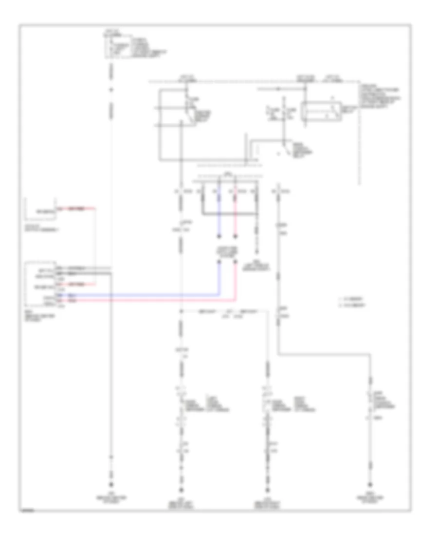
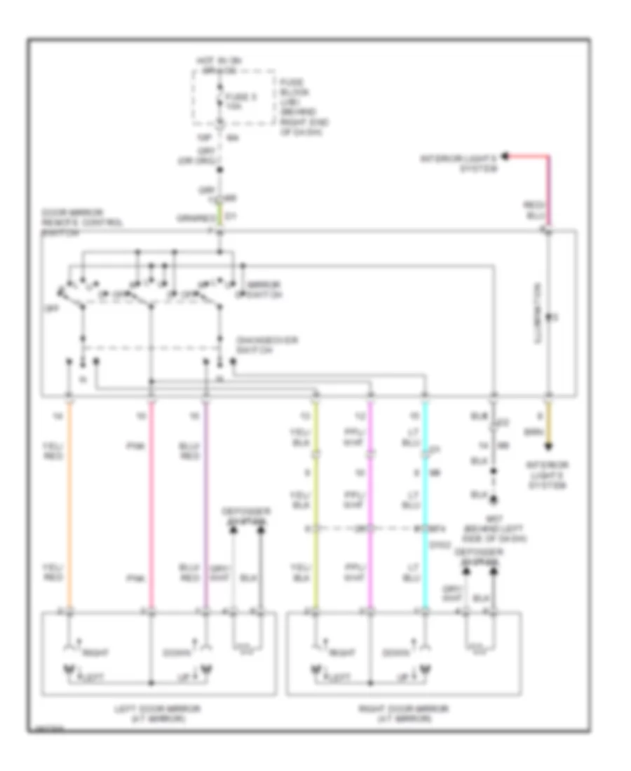
DEFOGGERS
Defoggers Wiring Diagram for Nissan Armada SL 2013
List of elements for Defoggers Wiring Diagram for Nissan Armada SL 2013:
- A/c & av switch assembly
- B42
- B49
- Bat (f/l)
- Bcm (behind center of dash)
- Can-h
- Can-l
- Computer data lines system
- Cpu
- D101
- D102
- D402
- D406
- D603 (rear center of roof)
- D604
- Door mirror defogger
- E120
- E122
- E124
- E152
- E24 (left side of engine compt)
- E36
- Fuse & fusible link box (at right rear of engine compt)
- Fuse 15a
- Fusible link f 50a
- Gnd (pwr)
- Heated mirror relay
- Hot at all times
- Hot in on or start
- Ignition relay
- Ipdm e/r (intelligent power distribution module engine room) (at right rear of engine compt)
- Left door mirror (at mirror)
- M18
- M19
- M20
- M31 100g
- M57 (behind left side of dash)
- M61 (behind center of dash)
- M74
- M75
- M79 (behind right side of dash)
- Pnk
- Rear window defogger
- Rear window defogger relay
- Right door mirror (at mirror)
- Rr def sw
- Rr defog
- W/ memory
- W/o memory
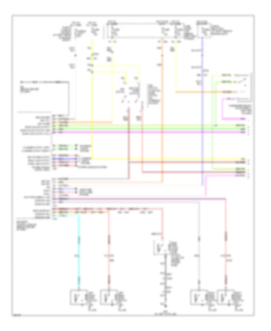
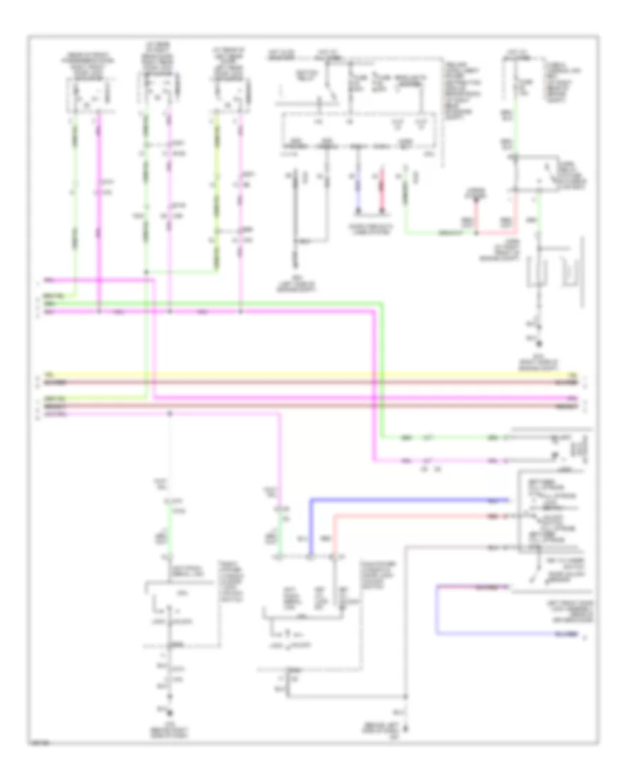
ELECTRONIC SUSPENSION
Electronic Suspension Wiring Diagram for Nissan Armada SL 2013
List of elements for Electronic Suspension Wiring Diagram for Nissan Armada SL 2013:
- 12j m40
- 13j
- 14j m40
- 17j
- 1q m39
- 25c
- 27c
- 28c
- 29c
- 44g m31
- 48c c1
- 5p m4
- Alt in
- B19 (at left "d" pillar)
- B40
- B40 red
- B69
- Bat
- Ck susp ind
- Combination meter
- Comp rly out
- Compressor motor relay (at right front of engine compt)
- Data link connector (behind lower left side of dash)
- E130
- E131
- E201
- E205
- E24 (left side of engine compt)
- E34
- E40
- E41
- Exh vlv out
- Fuse & fusible link box (at right rear of engine compt)
- Fuse 10a
- Fuse block (j/b) (behind right end of dash)
- Fusible link g 30a
- Generator
- Gnd
- Height sensor (at right rear corner of vehicle)
- Hot at all times
- Hot in on or start
- Ign
- K-line
- Lamp output
- M24
- M61 (behind center of dash)
- Red
- Sens gnd
- Sens input
- Suspension air compressor (at right rear corner of vehicle)
- Suspension control unit (behind left rear quarterpanel)
- Unified meter control unit (w/ information display)
- Vref out
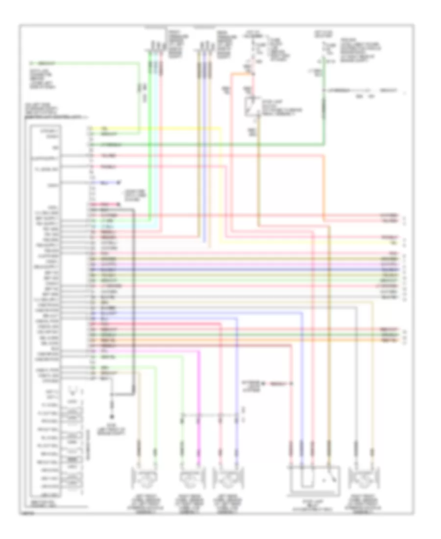
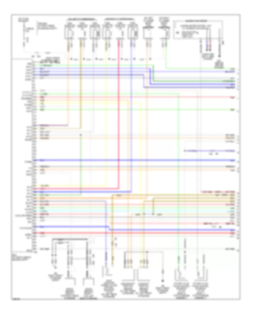
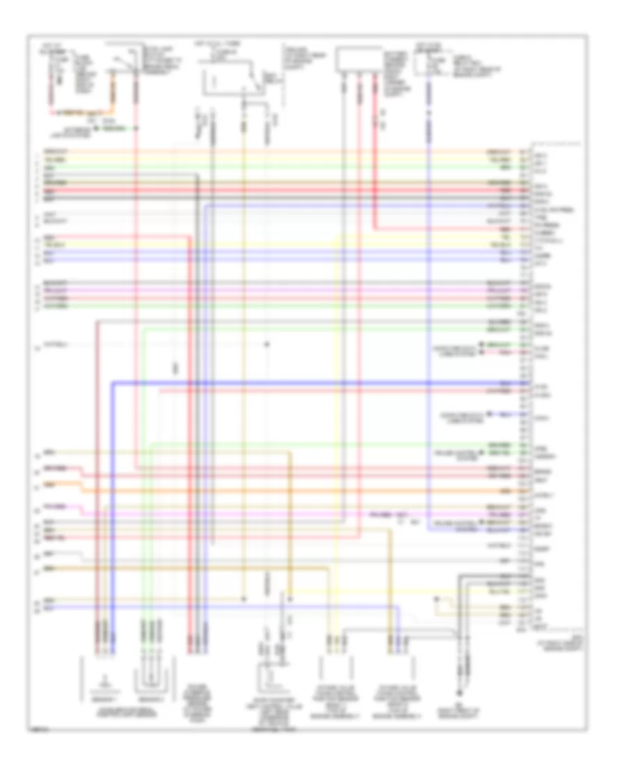
ENGINE PERFORMANCE
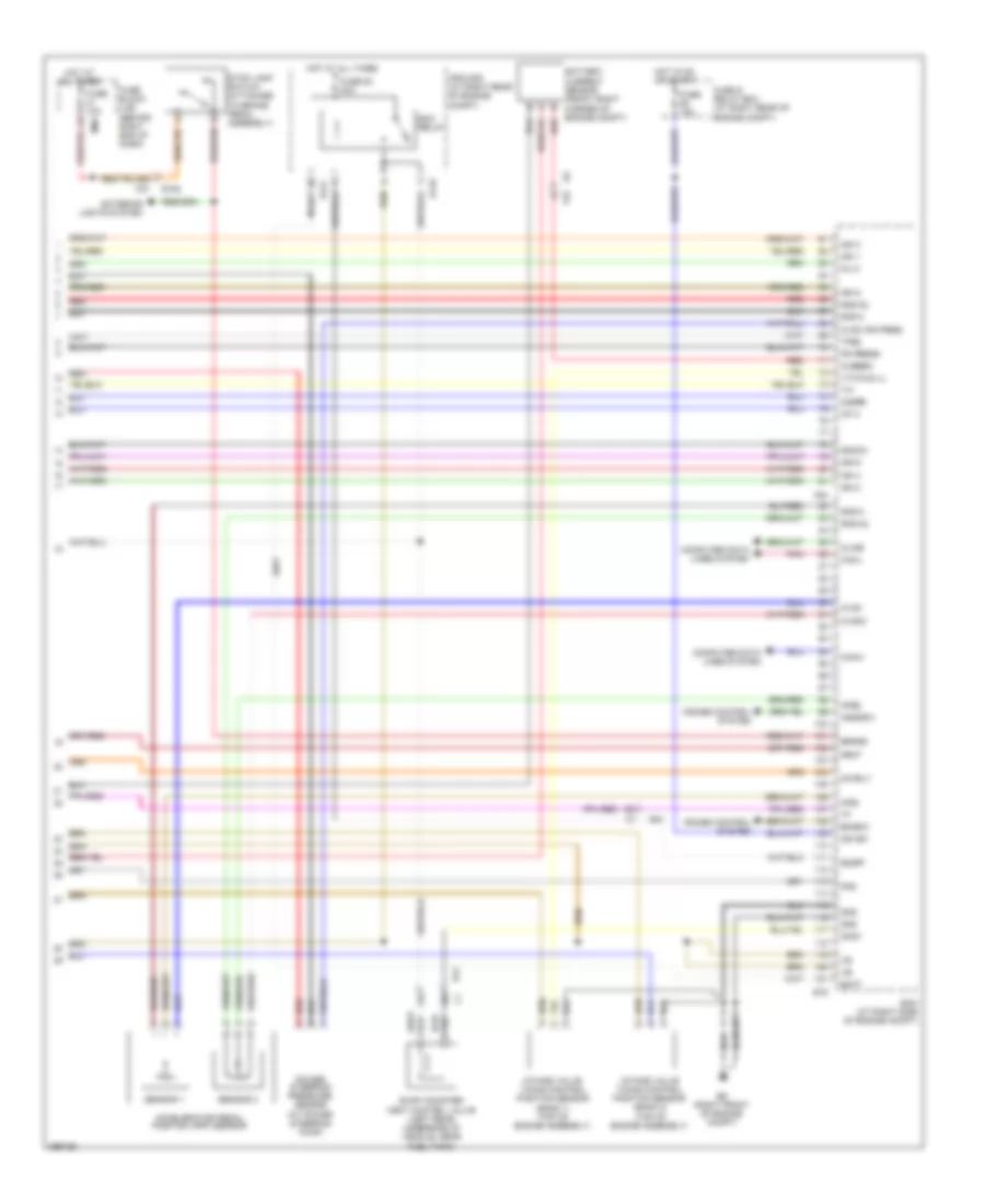
5.6L
5.6L, Engine Performance Wiring Diagram (1 of 4) for Nissan Armada SL 2013
List of elements for 5.6L, Engine Performance Wiring Diagram (1 of 4) for Nissan Armada SL 2013:
- (mil)
- (on left cylinder bank)
- (on left cylinder bank) fuel injector 7
- (on right cylinder bank)
- (on right cylinder bank) fuel injector 8
- (right front of engine compt) e9
- 67g
- A/f 1
- A/f+1
- A/f+2
- Af h2
- Af-h1
- Af-h2
- Avcc
- Avcc (pd pres)
- Avcc2
- C-vtc (l)
- C-vtc (r)
- Camshaft position sensor (phase) (at left front of engine)
- Combination meter
- Computer data lines system
- Crankshaft position sensor (at left rear of engine)
- E119
- E152
- E9 (right front of engine compt)
- Ecm (at right side of engine compt)
- Evap
- Evap canister purge volume control solenoid valve (on left rear of engine)
- F14
- F201
- F26
- F32
- F54
- Ftprs
- Fuel injector
- Fuse 55 15a
- Gnd
- Hot in on or start
- Ign 5
- Ign 7
- Inj 1
- Inj 2
- Inj 3
- Inj 4
- Inj 5
- Inj 6
- Inj 7
- Intake valve timing control solenoid valve (bank 1) (top of engine assembly)
- Intake valve timing control solenoid valve (bank 2) (top of engine assembly)
- Ipdm e/r (at right rear of engine compt)
- Knk1
- Knk2
- Knock sensor (bank 1) (top left rear of engine)
- Knock sensor (bank 2) (top right rear of engine)
- M24
- M31
- M61 (behind center of dash)
- Malfunction indicator lamp
- Mtr 1
- Mtr 2
- Nca
- O2hrl
- O2hrr
- O2srl
- Phase
- Pnk
- Pos
- Ps-press
- Qa+
- Red
- Tps1
- Unified meter control unit (w/ information display)
- Vmot
- Vtc pus (r)
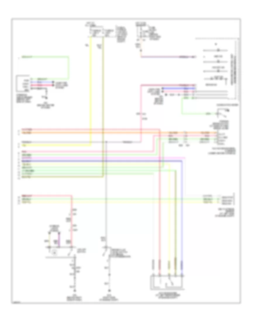
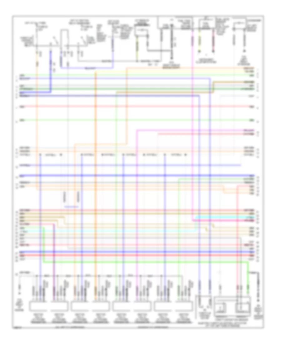
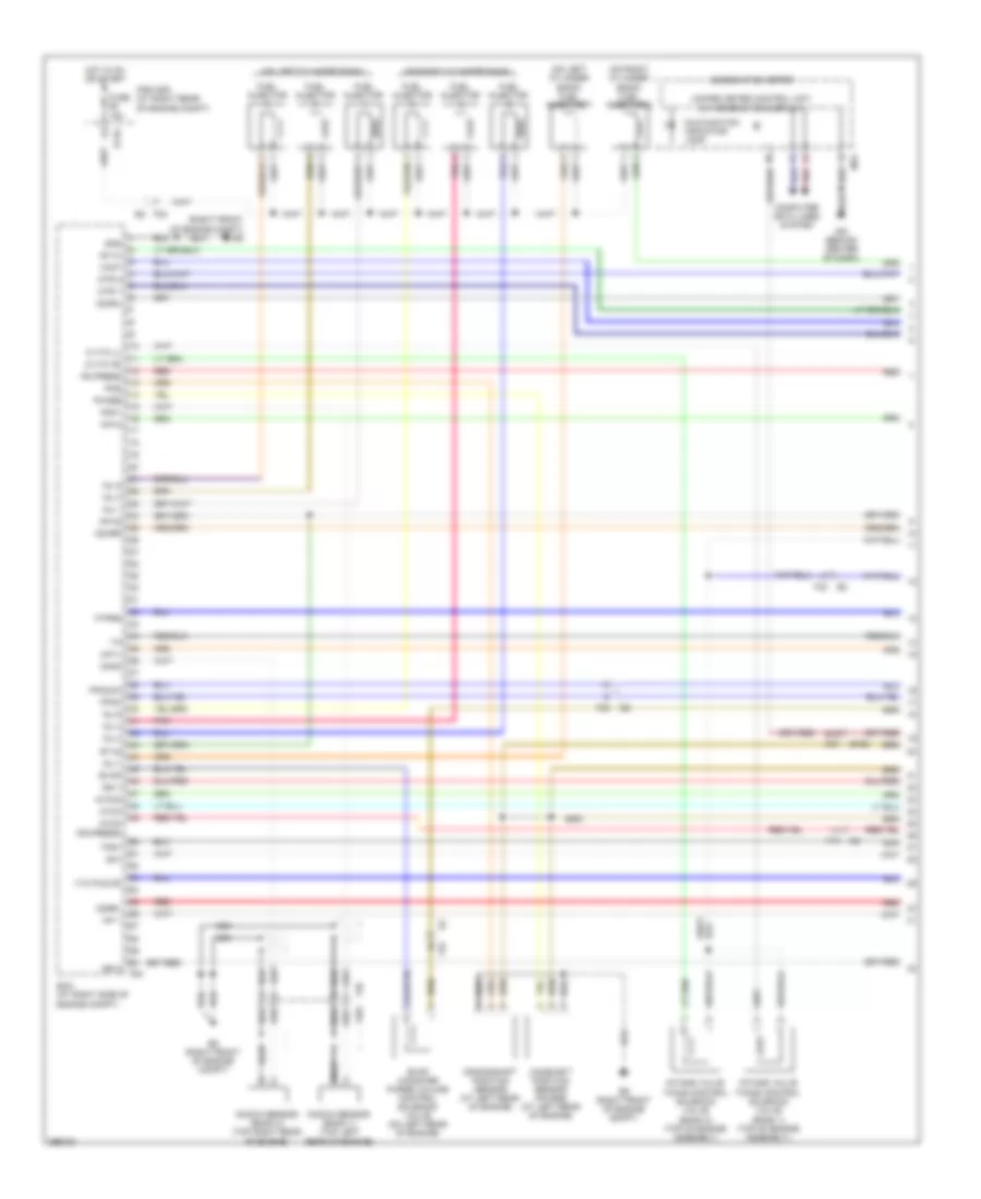
5.6L, Engine Performance Wiring Diagram (2 of 4) for Nissan Armada SL 2013
List of elements for 5.6L, Engine Performance Wiring Diagram (2 of 4) for Nissan Armada SL 2013:
- (at rear of engine) condenser 2
- (on left cylinder bank)
- (on right cylinder bank)
- 16c
- C1 e41
- Close
- Condenser (at left rear of engine)
- E119
- E122
- E15 (right side of engine compt)
- E41 c1
- E9 (right front of engine compt)
- Electric throttle control actuator (at top left side of engine)
- F16 (left front of engine)
- F32
- Fuel level sensor
- Fuel level sensor unit & fuel pump (on top of fuel tank)
- Fuel pump
- Fuel pump relay
- Fuel tank tempe- rature sensor
- Fuse & relay box (at right rear of engine compt)
- Fuse 10a
- Fuse 48 15a
- Fuse 52 20a
- Hot at all times
- Hot in on or start
- Hot w/ ignition relay energized
- Ignition coil 1 (w/ power transistor)
- Ignition coil 2 (w/ power transistor)
- Ignition coil 3 (w/ power transistor)
- Ignition coil 4 (w/ power transistor)
- Ignition coil 5 (w/ power transistor)
- Ignition coil 6 (w/ power transistor)
- Ignition coil 7 (w/ power transistor)
- Ignition coil 8 (w/ power transistor)
- Instrument cluster system
- Ipdm e/r (at right rear of engine compt)
- Nca
- Open
- Plug spark
- Red
- Sensor 1
- Sensor 2
- Spark plug
- Throttle control motor
- Throttle control motor relay
- Throttle position sensor
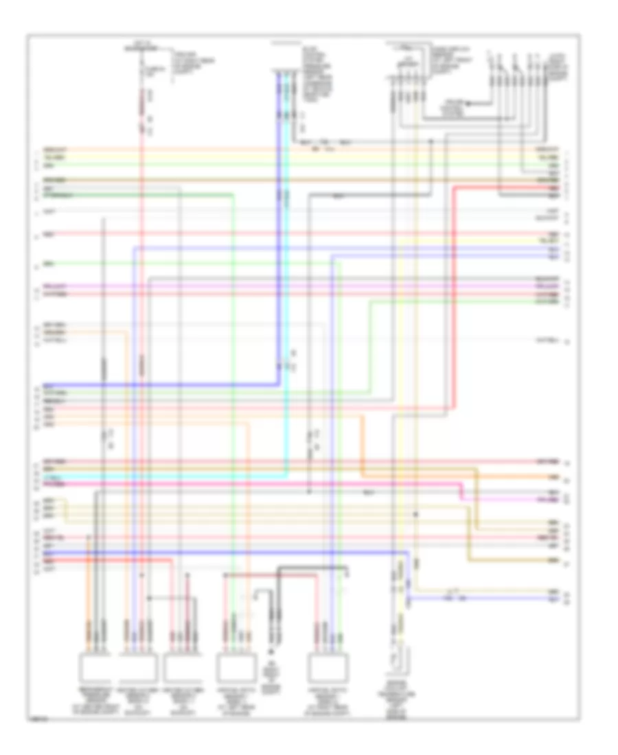
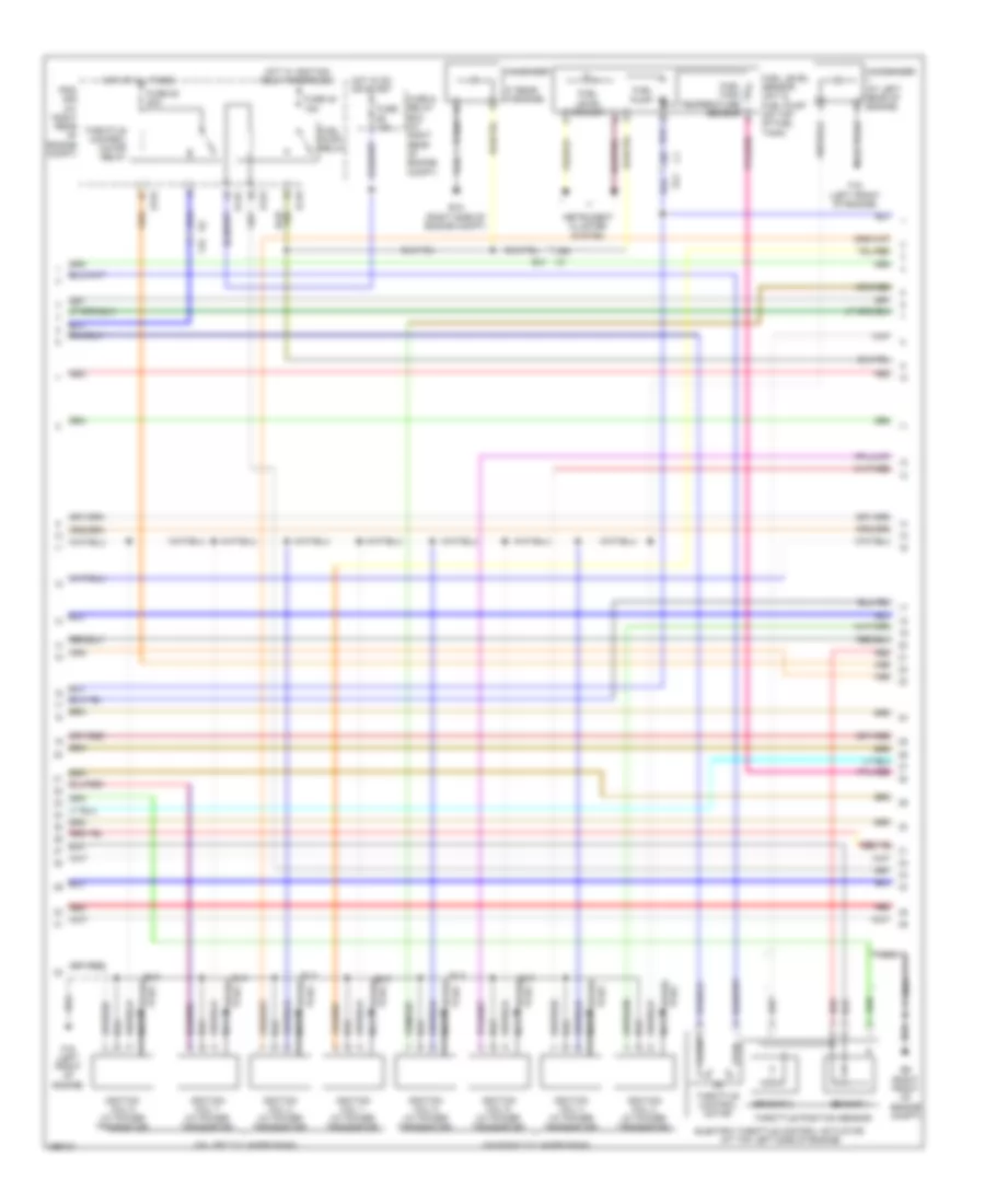
5.6L, Engine Performance Wiring Diagram (3 of 4) for Nissan Armada SL 2013
List of elements for 5.6L, Engine Performance Wiring Diagram (3 of 4) for Nissan Armada SL 2013:
- 18c
- 19c
- 20c
- Air/fuel ratio sensor 1 (bank 1) (at left rear of engine)
- Air/fuel ratio sensor 1 (bank 2) (at right rear of engine compt)
- C1 e41
- Cruise control system
- E119
- E9 (right front of engine compt)
- Engine coolant temperature sensor (left side of engine)
- Evap control system pressure sensor (left rear underside of vehicle, near fuel tank)
- F14
- F201
- F26
- F32
- Fuse 54 15a
- Heated oxygen sensor 2 (bank 1) (on exhaust)
- Heated oxygen sensor 2 (bank 2) (on exhaust)
- Hot in on or start
- Iat sensor
- Ipdm e/r (at right rear of engine compt)
- J/c-f01 (right side of engine compt)
- Mass airflow sensor (at left front of engine compt)
- Nca
- Red
- Refrigerant pressure sensor (at center front of engine compt)
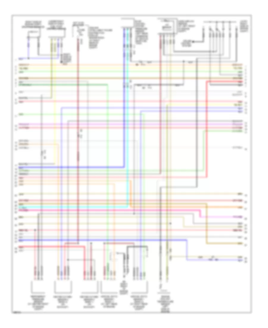
5.6L, Engine Performance Wiring Diagram (4 of 4) for Nissan Armada SL 2013
List of elements for 5.6L, Engine Performance Wiring Diagram (4 of 4) for Nissan Armada SL 2013:
- 15c
- 21c
- 36g
- 42c
- A/f 2
- Accelerator pedal position (app) sensor
- Aps2
- Apsi
- Ascdsw
- Avcc
- Avcc (ps pres)
- Avcc2
- Batt
- Battery current sensor (front right corner of engine compt)
- Bncsw
- Brake
- Can h
- Can l
- Cdcv
- Computer data lines system
- Cruise control system
- Cursen
- E119
- E121
- E152
- E16
- E41
- E9 (right front of engine compt)
- Ecm (at right side of engine compt)
- Ecm relay
- Evap canister vent control valve (left rear underside of vehicle, near fuel tank)
- Exterior lights system
- F32
- F54
- Fpr
- Fuse & relay box (at right rear of engine compt)
- Fuse 10a
- Fuse 53 20a
- Fuse block (j/b) (behind right end of dash)
- Gnd
- Gnd 02
- Gnd a
- Gnd a2
- Hot at all times
- Hot in on or start
- Ign 1
- Ign 2
- Ign 3
- Ign 4
- Ign 6
- Ign 8
- Ign sw
- Inj 8
- Intake valve timing control position sensor (bank 1) (top of engine assembly)
- Intake valve timing control position sensor (bank 2) (top of engine assembly)
- Ipdm e/r (at right rear of engine compt)
- Kline
- M31
- M60
- Motrly
- Neut
- O2srr
- Pd press
- Pnk
- Power steering pressure sensor (at power steering pump)
- Red
- Sensor 1
- Sensor 2
- Ssoff
- Stop lamp switch (attached to brake pedal assembly)
- Tps2
- Vtc pus (l)
5.6L FLEX FUEL
5.6L Flex Fuel, Engine Performance Wiring Diagram (1 of 4) for Nissan Armada SL 2013
List of elements for 5.6L Flex Fuel, Engine Performance Wiring Diagram (1 of 4) for Nissan Armada SL 2013:
- (on left cylinder bank)
- (on left cylinder bank) fuel injector 7
- (on right cylinder bank)
- (on right cylinder bank) fuel injector 8
- (right front of engine compt) e9
- 67g m31
- A/f 1
- A/f+1
- A/f+2
- Af h1
- Af h2
- Af-h2
- Avcc
- Avcc (pd-press)
- Avcc2
- C-vtc (l)
- C-vtc (r)
- Camshaft position sensor (phase) (at left rear of engine)
- Combination meter
- Computer data lines system
- Crankshaft position sensor (at left rear of engine)
- E119
- E152
- E9 (right front of engine compt)
- Ecm (at right side of engine compt)
- Evap
- Evap canister purge volume control solenoid valve (on left rear of engine)
- F14
- F26 f201
- F32
- F32 e2
- F54
- Fpcm
- Fpcmck
- Ftprs
- Fuel injector
- Fuse 15a
- Gnd
- Hot in on or start
- Ign 5
- Ign 7
- Inj 1
- Inj 2
- Inj 3
- Inj 4
- Inj 5
- Inj 6
- Inj 7
- Intake valve timing control solenoid valve (bank 1) (top of engine assembly)
- Intake valve timing control solenoid valve (bank 2) (top of engine assembly)
- Ipdm e/r (at right rear of engine compt)
- Knk1
- Knk2
- Knock sensor (bank 1) (top left rear of engine)
- Knock sensor (bank 2) (top right rear of engine)
- M24
- M61 (behind center of dash)
- Malfunction indicator lamp
- Mtr 1
- Mtr 2
- Nca
- O2hrl
- O2hrr
- O2srl
- Phase
- Pnk
- Pos
- Ps press
- Qa+
- Red
- Tps1
- Unified meter control unit (w/ information display)
- Vmot
- Vtc pus (r)
5.6L Flex Fuel, Engine Performance Wiring Diagram (2 of 4) for Nissan Armada SL 2013
List of elements for 5.6L Flex Fuel, Engine Performance Wiring Diagram (2 of 4) for Nissan Armada SL 2013:
- (on left cylinder bank)
- (on right cylinder bank)
- 16c
- 52c
- C1 e41
- Close
- Condenser (at left rear of engine)
- Condenser (at rear of engine)
- E119
- E122
- E15 (right side of engine compt)
- E2 f32
- E41
- E9 (right front of engine compt)
- Electric throttle control actuator (at top left side of engine)
- F16 (left front of engine)
- Fuel level sensor
- Fuel level sensor unit & fuel pump (on top of fuel tank)
- Fuel pump
- Fuel pump relay
- Fuel tank temperature sensor
- Fuse & relay box (at right rear of engine compt)
- Fuse 10a
- Fuse 48 15a
- Fuse 52 20a
- Hot at all times
- Hot in on or start
- Hot w/ ignition relay energized
- Ignition coil 1 (w/ power transistor)
- Ignition coil 2 (w/ power transistor)
- Ignition coil 3 (w/ power transistor)
- Ignition coil 4 (w/ power transistor)
- Ignition coil 5 (w/ power transistor)
- Ignition coil 6 (w/ power transistor)
- Ignition coil 7 (w/ power transistor)
- Ignition coil 8 (w/ power transistor)
- Instrument cluster system
- Ipdm e/r (at right rear of engine compt)
- Nca
- Open
- Plug spark
- Red
- Sensor 1
- Sensor 2
- Spark plug
- Throttle control motor
- Throttle control motor relay
- Throttle position sensor
5.6L Flex Fuel, Engine Performance Wiring Diagram (3 of 4) for Nissan Armada SL 2013
List of elements for 5.6L Flex Fuel, Engine Performance Wiring Diagram (3 of 4) for Nissan Armada SL 2013:
- (right side of engine compt) dropping resistor
- (under right side of dash) fuel pump control module
- 18c
- 19c
- 20c
- Air/fuel ratio sensor 1 (bank 1) (at left rear of engine)
- Air/fuel ratio sensor 1 (bank 2) (at right rear of engine compt)
- C1 e41
- Cruise control system
- E119
- E9 (right front of engine compt)
- Engine compt) e15
- Engine coolant temperature sensor (left side of engine)
- Evap control system pressure sensor (left rear underside of vehicle, near fuel tank)
- F14
- F201
- F26
- F32
- Fuse 15a
- Heated oxygen sensor 2 (bank 1) (on exhaust)
- Heated oxygen sensor 2 (bank 2) (on exhaust)
- Hot in on or start
- Iat sensor
- Ipdm e/r (intelligent power distribution module engine room) (at right rear of engine compt)
- J/c-f01 (right side of engine compt)
- Mass airflow sensor (at left front of engine compt)
- Nca
- Red
- Refrigerant pressure sensor (at center front of engine compt)
5.6L Flex Fuel, Engine Performance Wiring Diagram (4 of 4) for Nissan Armada SL 2013
List of elements for 5.6L Flex Fuel, Engine Performance Wiring Diagram (4 of 4) for Nissan Armada SL 2013:
- 15c
- 21c
- 36g
- 42c
- A/f 2
- Accelerator pedal position (app) sensor
- Aps2
- Apsi
- Ascdsw
- Avcc
- Avcc (ps pres)
- Avcc2
- Batt
- Battery current sensor (front right corner of engine compt)
- Bncsw
- Brake
- Can h
- Can l
- Cdcv
- Computer data lines system
- Cruise control system
- Cursen
- E119
- E121
- E152
- E16
- E41
- E9 (right front of engine compt)
- Ecm (at right side of engine compt)
- Ecm relay
- Evap canister vent control value (left rear underside of vehicle, near fuel tank)
- Exterior lights system
- F32
- F54
- Fpr
- Fuse & relay box (at right rear of engine compt)
- Fuse 10a
- Fuse 53 20a
- Fuse block (j/b) (behind right end of dash)
- Gnd
- Gnd 02
- Gnd a
- Gnd a2
- Hot at all times
- Hot in on or start
- Ign 1
- Ign 2
- Ign 3
- Ign 4
- Ign 6
- Ign 8
- Ign sw
- Inj 8
- Intake valve timing control position sensor (bank 1) (top of engine assembly)
- Intake valve timing control position sensor (bank 2) (top of engine assembly)
- Ipdm e/r (at right rear of engine compt)
- Kline
- M31
- M60
- Motrly
- Neut
- O2srr
- Pd press
- Pnk
- Power steering pressure sensor (at power steering pump)
- Red
- Sensor 1
- Sensor 2
- Ssoff
- Stop lamp switch (attached to brake pedal assembly
- Tps2
- Vtc pus (l)
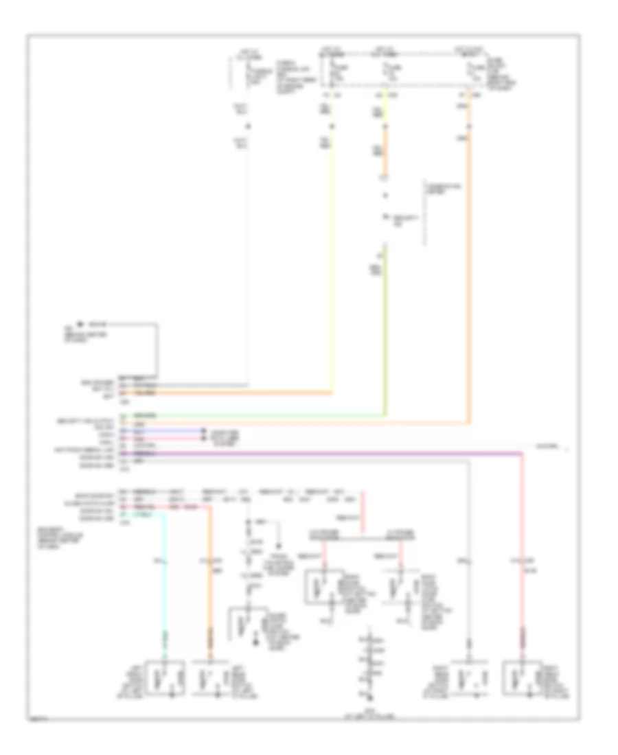
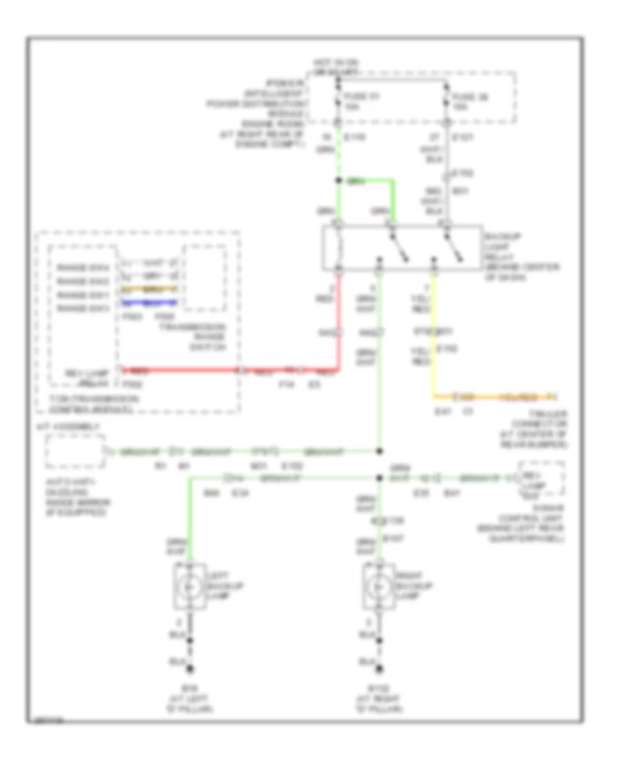
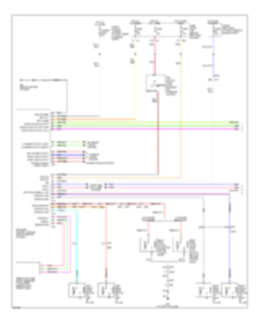
EXTERIOR LIGHTS
Backup Lamps Wiring Diagram for Nissan Armada SL 2013
List of elements for Backup Lamps Wiring Diagram for Nissan Armada SL 2013:
- 37g
- 64g
- 94g
- 97g m31
- A/t assembly
- Auto anti- dazzling inside mirror (if equipped)
- B132 (at right "d" pillar)
- B19 (at left "d" pillar)
- B40
- B41
- Backup light relay (behind center of dash)
- E119
- E121
- E139
- E152
- E34
- E35
- E41
- F14
- F502
- F503
- F505
- Fuse 38 10a
- Fuse 51 10a
- Hot in on or start
- Ipdm e/r (intelligent power distribution module engine room) (at right rear of engine compt)
- Left backup lamp
- M31
- Range-sw1
- Range-sw2
- Range-sw3
- Range-sw4
- Red
- Rev lamp relay
- Rev lamp sig
- Right backup lamp
- Sonar control unit (behind left rear quarterpanel)
- Tcm (transmission control module)
- Trailer connector (at center of rear bumper)
- Transmission range switch
Exterior Lamps & Trailer Connector Wiring Diagram (1 of 2) for Nissan Armada SL 2013
List of elements for Exterior Lamps & Trailer Connector Wiring Diagram (1 of 2) for Nissan Armada SL 2013:
- (at mirror) (w/ automatic drive positioner) left door mirror
- (behind center of dash) m61
- 17c c1
- 57g
- 58g
- 92g
- 99g m31
- B105
- B107
- B130
- B132 (at right "d" pillar)
- B19 (at left "d" pillar)
- B35
- B40
- B48
- B70
- Backup lamps circuit
- Bat (f/l)
- Bcm (behind center of dash)
- Can-h
- Can-l
- Combi sw input 1
- Combi sw input 2
- Combi sw input 3
- Combi sw input 4
- Combi sw input 5
- Combi sw out 1
- Combi sw out 2
- Combi sw out 3
- Combi sw out 4
- Combi sw out 5
- Combination switch (lighting & turn sig switch)
- D101
- D102
- D401
- Door sw (as)
- Door sw (dr)
- Door sw (rl)
- Door sw (rr)
- E10
- E139
- E15 (right side of engine compt)
- E152
- E24 (left side of engine compt)
- E34
- E34 b40
- E41
- Electric brake (pre-wiring) (behind dash, left side of steering column)
- Flasher out (left)
- Flasher out (right)
- Fuse & fusible link box (at right rear of engine compt)
- Fuse & relay box (at right rear of engine compt)
- Fuse 10a
- Fuse 15a
- Fusible link f 50a
- Fusible link j 30a
- Fusible link k (w/ trailer tow) 40a
- Gnd
- Hazard sw
- Hazard switch
- High- mounted stop lamp
- Hot at all times
- Hot in on or start
- Ign sw
- Input 1
- Input 2
- Input 3
- Input 4
- Input 5
- Interior lights system
- Interior lights system computer data lines system
- Left rear combination lamp
- Left trailer turn relay (in fuse & relay box)
- M158
- M18
- M19
- M20
- M31
- M31 38g
- M31 39g
- M57 (behind left side of dash)
- M74
- M75
- M79 (behind right side of dash)
- Output 1
- Output 2
- Output 3
- Output 4
- Output 5
- Park- ing
- Pnk
- Red
- Right door mirror (w/ automatic drive positioner) (at mirror)
- Right front combination lamp
- Right rear combination lamp
- Right trailer turn relay (in fuse & relay box)
- Stop
- Tail
- Trailer connector (at center of rear bumper)
- Trailer lt flasher
- Trailer rt flasher
- Trailer tow relay 2 (in fuse & relay box)
- Turn
- Turn sig
- W/ trailer tow
Exterior Lamps & Trailer Connector Wiring Diagram (2 of 2) for Nissan Armada SL 2013
List of elements for Exterior Lamps & Trailer Connector Wiring Diagram (2 of 2) for Nissan Armada SL 2013:
- (w/ information display) unified meter control unit
- +ig
- 46c c1
- 47g m31
- 5p m4
- 6t m60
- 93g m31
- Abs actuator & electric unit (control unit) (on left side of engine compt)
- Abs/tcs/vdc control unit
- Bls
- Brl out
- C101
- Can-h
- Can-l
- Combination meter
- Computer data lines system
- Cpu
- E118
- E119
- E122
- E123
- E124
- E15 (right side of engine compt)
- E152
- E24 (left side of engine compt)
- E27
- E41
- Fuse 10a
- Fuse 32 10a
- Fuse 51 10a
- Fuse 53 20a
- Fuse block (j/b) (behind right end of dash)
- Fusible link box (battery) (right side of engine compt)
- Fusible link d 80a
- Gnd (power)
- Gnd (signal)
- Hot at all times
- Hot in on or start
- Ignition relay
- Interior lights system
- Ipdm e/r (intell- igent power distri- bution module engine room) (at right rear of engine compt)
- Left front combination lamp
- Left license plate lamp
- Left turn ind
- M24
- M60 1t
- M61 (behind center of dash)
- Park- ing
- Pnk
- Red
- Right license plate lamp
- Right turn ind
- Shift interlock system
- Stop lamp relay (in fuse & relay box)
- Stop lamp switch (attached to brake pedal assembly)
- Tail lamp relay
- Tail/l rly
- Trailer tow relay 1 (behind left side of dash)
- Turn
GROUND DISTRIBUTION
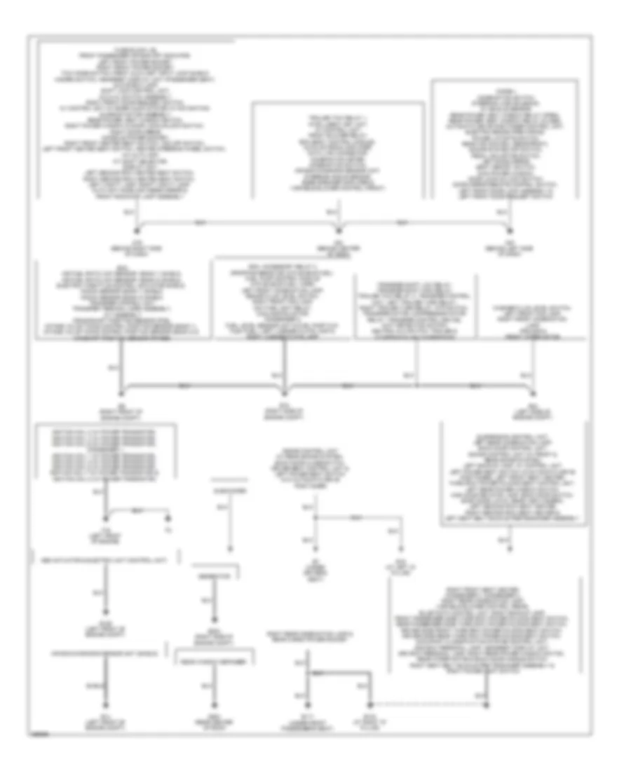
Ground Distribution Wiring Diagram for Nissan Armada SL 2013
List of elements for Ground Distribution Wiring Diagram for Nissan Armada SL 2013:
- A/c auto amp, a/t shift selector, display unit, left second row heated seat switch, right second row heated seat switch, left vanity lamp, right vanity lamp, auto anti dazzling inside mirror & front room/map lamp assembly
- Abs actuator & electric unit (control unit)
- Air bag diagnosis sensor unit (shield)
- B117 (under front passenger's seat)
- B132 (at right "d" pillar)
- B19 (at left "d" pillar)
- B7 (under driver's seat)
- D603 (rear center of roof)
- Diode-1, combination switch, steering lock solenoid, in vehicle sensor, rear power vent window relay (open), rear power vent window relay (close), automatic drive positioner control unit, electric brake (pre-wiring), power liftgate switch, rear air control (rear/front), sonar system off switch, pedal adjusting switch, left door mirror, seat memory switch, main power window, door lock/un lock switch, door mirror remote control switch, left front door lock assembly & left front door request switch
- E126 (left front of engine compt)
- E14 (left front of engine compt)
- E15 (right side of engine compt)
- E203 (right side of engine compt)
- E24 (left side of engine compt)
- E9 (right front of engine compt)
- Ecm, accessory relay 2 dropping resistor (w/flexible fuel), fuel pump control module (w/flexible fuel), horn, left front combination lamp, brake fluid level switch, right front fog lamp, daytime light relay, cooling fan motor, condenser 2, fuel level sensor unit & fuel pump (w/o flex fuel), left license plate lamp & right license plate lamp
- Ecm, air fuel ratio (a/f) sensor1 (bank 1) shield, air fuel ratio (a/f) sensor1 (bank 2) shield, electric throttle control actuator shield, knock sensor (bank 1) shield, knock sensor (bank 2) shield, transfer control unit, transfer terminal cord assembly, a/t assembly, crankshaft position sensor (pos), intake valve timing control position sensor (bank 1), intake valve timing control position sensor (bank 2) & camshaft position sensor (phase)
- F16 (left front of engine)
- Fuse block j/b, front passenger air bag off indicator, left front power socket, right front power socket, tow mode switch, front auxiliary input jack shield hazard switch, headrest display unit (passenger seat) glove box lamp, shift lock control unit, a/c & av switch assembly, right front door request switch, av control unit (w/ bose audio system w/ navigation) sunroof motor assembly, rear power vent window switch, right power window & door lock/unlock switch, right door mirror, console power socket, right front heated seat switch, vdc off switch, left front heated seat switch, heated steering wheel switch,
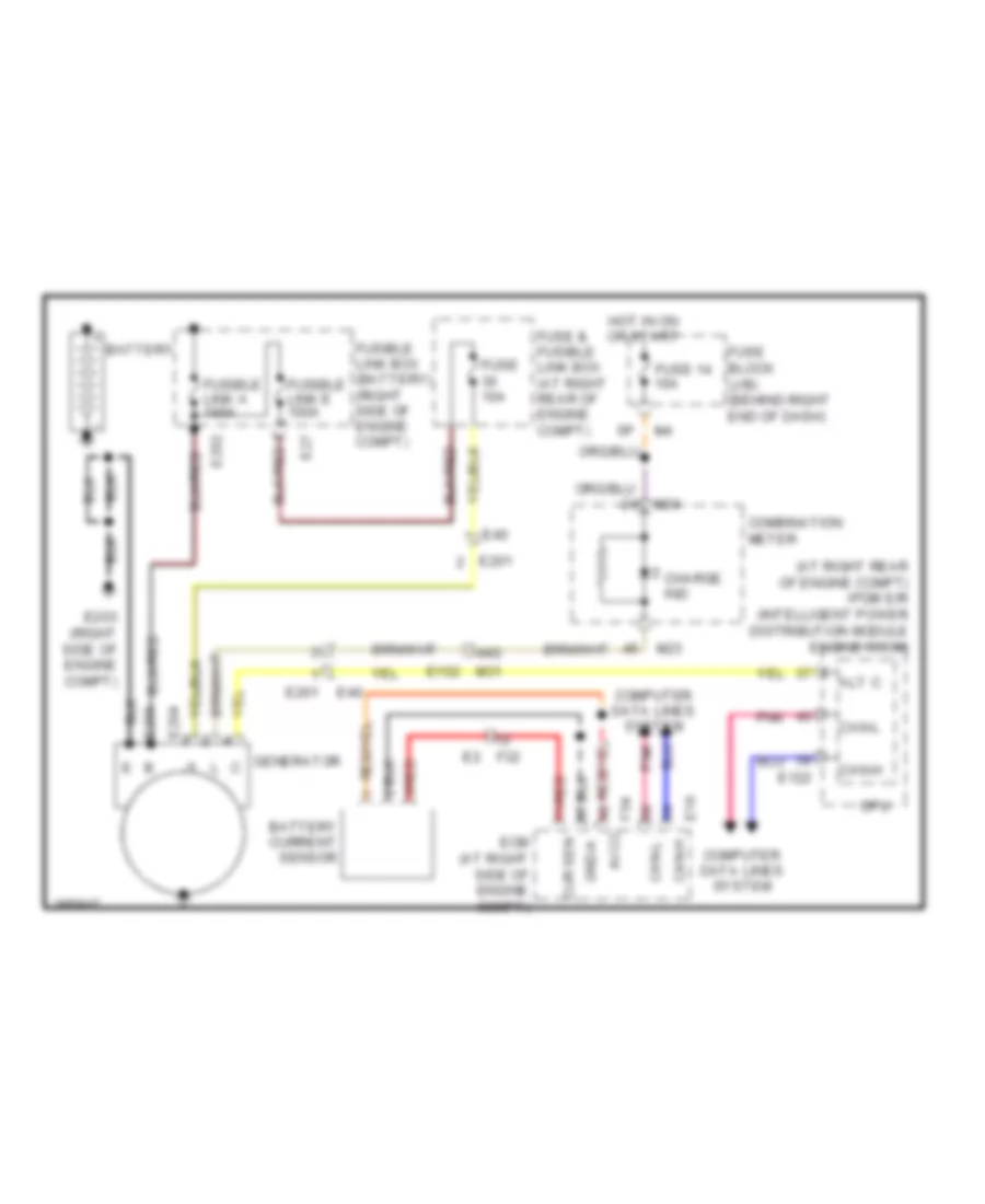
- Generator
- Ignition coil 2 (w/ power transistor), ignition coil 4 (w/ power transistor), ignition coil 6 (w/ power transistor), condenser 1, ignition coil 1 (w/ power transistor), ignition coil 3 (w/ power transistor), ignition coil 5 (w/ power transistor), ignition coil 7 (w/ power transistor) & ignition coil 8 (w/ power transistor)
- M57 (behind left side of dash)
- M61 (behind center of dash)
- M79 (behind right side of dash)
- Rear window defogger
- Right rear combination lamp & rear cargo power socket
- Shield
- Sonar control unit (w/ rear sonar system), back door close switch, driver seat control unit & left power seat switch (w/o automatic drive positioner)
- Subwoofer
- Suspension control unit, left rear combination lamp, back door control unit, sonar control unit (w/ front & rear sonar system), left backup lamp, av control unit left power seat switch (w/automatic drive positioner), left front seat heater, third row power folding seat control unit, left rear power window switch, high mounted stop lamp, back door switch, back door latch, rear view camera, left second row seat heater, right second row seat heater & left seat belt buckle pretensioner assembly
- Trailer tow relay 1, intelligent key unit, av control unit, front blower relay, bcm (body control module), nats antenna amplifier, data link connector, combination meter, combination switch, air bag diagnosis sensor unit, steering angle sensor, bose speaker amplifier & variable blower control (front)
- Transfer shift low relay, transfer shift high relay, trailer tow relay 2, transfer control unit, left trailer turn relay, right trailer turn relay, atp switch, transfer motor, compressor motor relay, transfer control device, wait detection switch, neutral-4lo switch, trailer & suspension air compressor
- Washer fluid level switch, left front fog lamp, right front combination lamp, ipdm e/r & front wiper motor
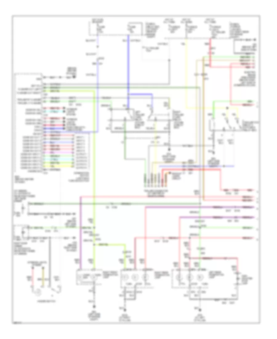
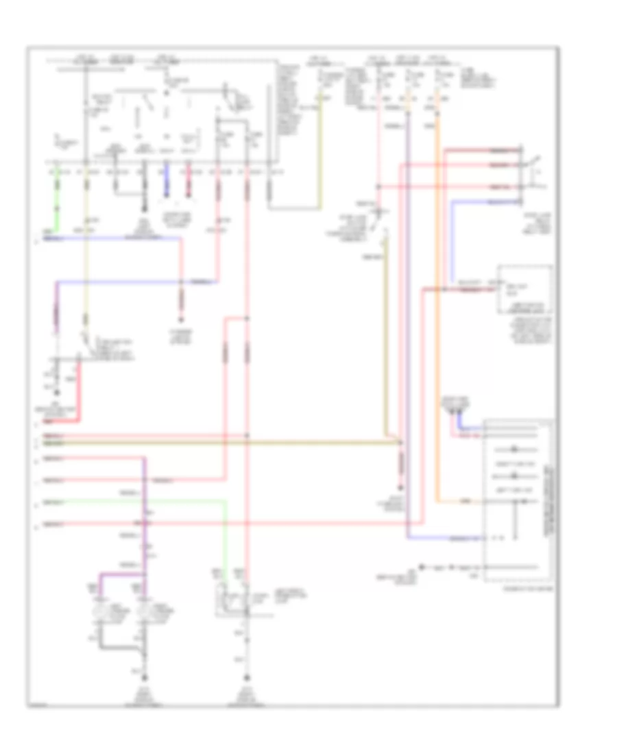
HEADLIGHTS
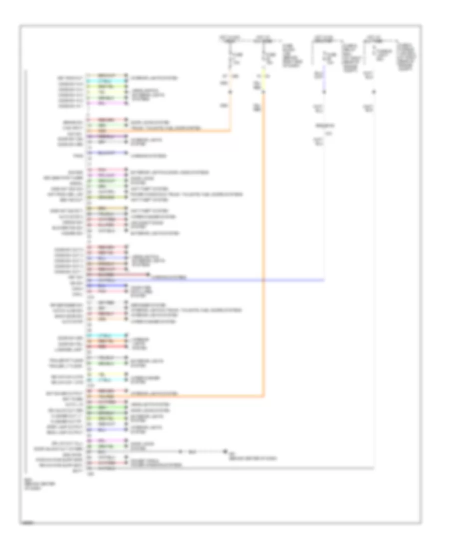
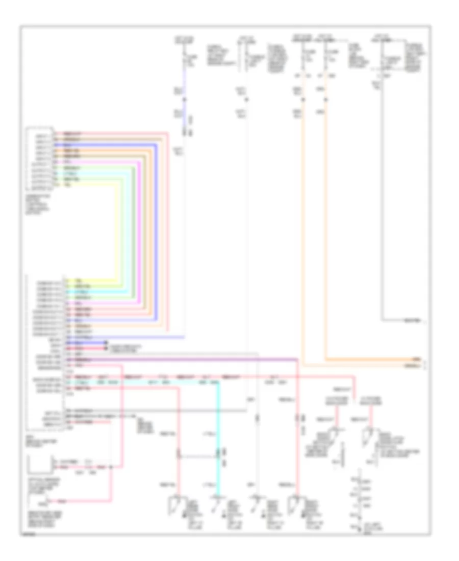
Headlights Wiring Diagram, with DRL (1 of 2) for Nissan Armada SL 2013
List of elements for Headlights Wiring Diagram, with DRL (1 of 2) for Nissan Armada SL 2013:
- (at bottom center of back door)
- (at left 'd' pillar) b19
- (behind center of dash)
- (j/b) (behind right end of dash)
- 15a
- 21a
- 21j
- 26a
- 30j
- 99g
- B111
- B149
- B43
- B48
- B69
- Back door latch (door ajar switch)
- Back door sw
- Back door switch (at bottom center of back door)
- Bat (f/l)
- Bcm
- Can-h
- Can-l
- Comb sw in 1
- Comb sw in 2
- Comb sw in 3
- Comb sw in 4
- Comb sw in 5
- Comb sw out 1
- Comb sw out 2
- Comb sw out 3
- Comb sw out 4
- Comb sw out 5
- Combination switch (lighting & turn signal switch)
- Computer data lines system
- D401
- D401 b48
- D405
- D501
- D501 d405
- Door sw (as)
- Door sw (dr)
- Door sw (rl)
- Door sw (rr)
- E152
- E27
- Fuse & fusible link box (at right rear of engine compt)
- Fuse & relay box (at right rear of engine compt)
- Fuse 10a
- Fuse block
- Fusible link box (battery) (right side of engine compt)
- Fusible link d 80a
- Fusible link f 50a
- Gnd
- Gnd (pow)
- Hot at all times
- Hot in on or start
- Ign sw
- Input 1
- Input 2
- Input 3
- Input 4
- Input 5
- Left front door switch (at left "b" pillar)
- Left rear door switch (at left "c" pillar)
- M18
- M19
- M20
- M301
- M31
- M36
- M36 b149
- M40
- M60
- M61 (behind center of dash)
- M65
- Optical sensor (w/ auto lamps) (top center of dash)
- Output 1
- Output 2
- Output 3
- Output 4
- Output 5
- Pnk
- Remote keyless entry receiver (behind right side of dash)
- Right front door switch (at right "b" pillar)
- Right rear door switch (at right "c" pillar)
- Sens in 2
- Sensor gnd
- W/ power back door
- W/o power back door
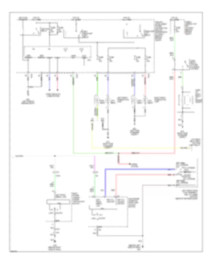
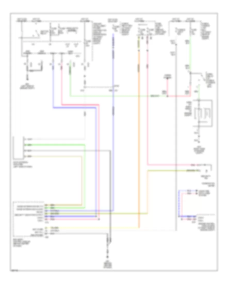
Headlights Wiring Diagram, with DRL (2 of 2) for Nissan Armada SL 2013
List of elements for Headlights Wiring Diagram, with DRL (2 of 2) for Nissan Armada SL 2013:
- +ig
- 44g
- Brake ind
- Can-h
- Can-l
- Charge ind
- Combination meter
- Computer
- Computer data lines system
- Cpu
- Data lines
- Daytime light relay (in fuse & relay box)
- Dtrl
- E118
- E119
- E122
- E123
- E124
- E15 (right side of engine compt)
- E152
- E201
- E203 (right side of engine compt)
- E205
- E206
- E24 (left side of engine compt)
- E40
- Fr fog
- Front fog lamp relay
- Fuse 10a
- Fuse 15a
- Fuse 20a
- Generator
- H/lp hi
- H/lp lo
- Headlamp high relay
- Headlamp low relay
- High beam
- High beam ind
- Hot at all times
- Hot in on or start
- Ignition relay
- Ipdm e/r (at right rear of engine compt)
- Left front combination lamp (headlamp)
- Left front fog lamp
- Low beam
- M23
- M24
- M31
- M61 (behind center of dash)
- Parking brake switch (at base of park brake lever)
- Pnk
- Pwr gnd
- Right front combination lamp (headlamp)
- Right front fog lamp
- Sig gnd
- System
- Unified meter control unit (w/ information display)
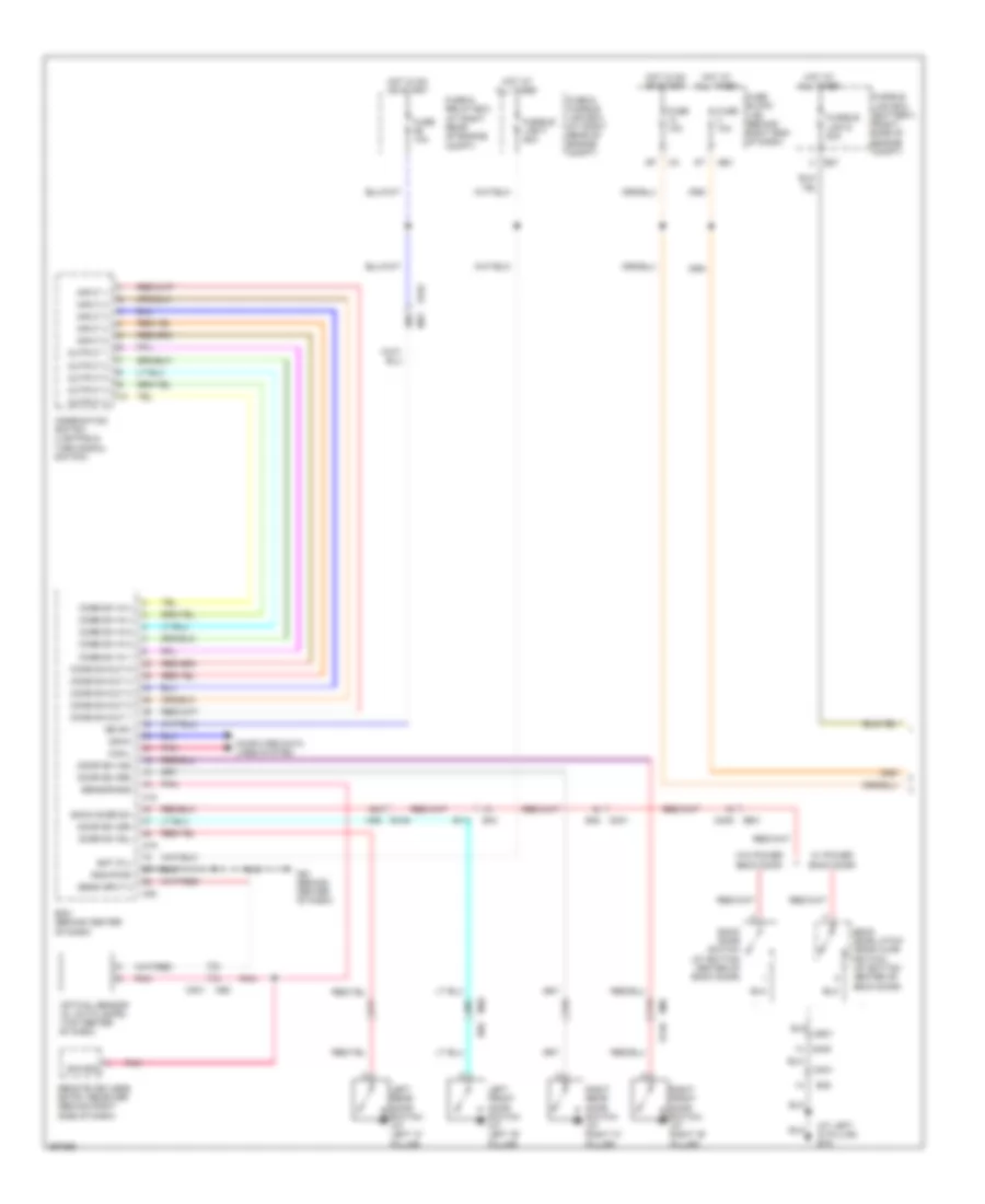
Headlights Wiring Diagram, without DRL (1 of 2) for Nissan Armada SL 2013
List of elements for Headlights Wiring Diagram, without DRL (1 of 2) for Nissan Armada SL 2013:
- (at left 'd' pillar) b19
- (j/b) (behind right end of dash)
- 15a
- 21a
- 21j
- 26a
- 30j
- 99g
- B111
- B149
- B43
- B48
- B48 d401
- B69
- Back door latch (door ajar switch) (at bottom center of back door)
- Back door sw
- Back door switch (at bottom center of back door)
- Bat (f/l)
- Bcm (behind center of dash)
- Can-h
- Can-l
- Comb sw in 1
- Comb sw in 2
- Comb sw in 3
- Comb sw in 4
- Comb sw in 5
- Comb sw out 1
- Comb sw out 2
- Comb sw out 3
- Comb sw out 4
- Comb sw out 5
- Combination switch (lighting & turn signal switch)
- Computer data lines system
- D401
- D405
- D405 d501
- D501
- Door sw (as)
- Door sw (dr)
- Door sw (rl)
- Door sw (rr)
- E152
- E27
- Fuse & fusible link box (at right rear of engine compt)
- Fuse & relay box (at right rear of engine compt)
- Fuse 10a
- Fuse block
- Fusible link box (battery) (right side of engine compt)
- Fusible link d 80a
- Fusible link f 50a
- Gnd (pwr)
- Hot at all times
- Hot in on or start
- Ign sw
- Input 1
- Input 2
- Input 3
- Input 4
- Input 5
- Left front door switch (at left "b" pillar)
- Left rear door switch (at left "c" pillar)
- M18
- M19
- M20
- M301
- M31
- M36
- M36 b149
- M40
- M60
- M61 (behind center of dash)
- M65
- Optical sensor (w/ auto lamps) (top center of dash)
- Output 1
- Output 2
- Output 3
- Output 4
- Output 5
- Pnk
- Remote keyless entry receiver (behind right side of dash)
- Right front door switch (at right "b" pillar)
- Right rear door switch (at right "c" pillar)
- Sens input 2
- Sensor gnd
- Sig gnd
- W/ power back door
- W/o power back door
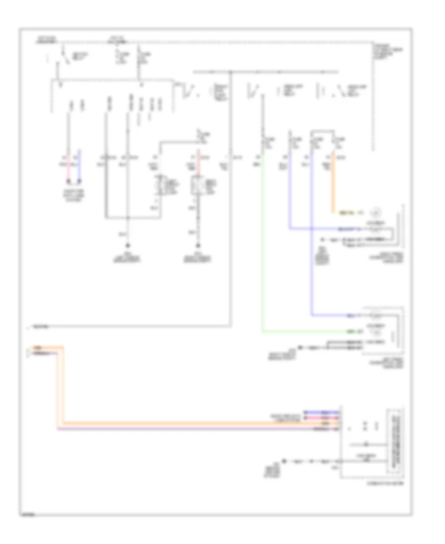
Headlights Wiring Diagram, without DRL (2 of 2) for Nissan Armada SL 2013
List of elements for Headlights Wiring Diagram, without DRL (2 of 2) for Nissan Armada SL 2013:
- (w/ informaton display)
- +ig
- Can-h
- Can-l
- Combination meter
- Computer
- Computer data lines system
- Cpu
- Data lines
- E118
- E122
- E123
- E124
- E15 (right side of engine compt)
- E24 (left side of engine compt)
- Fr fog
- Front fog lamp relay
- Fuse 10a
- Fuse 15a
- Fuse 20a
- H/lp hi
- H/lp lo
- Headlamp high relay
- Headlamp low relay
- High beam
- High beam ind
- Hot at all times
- Hot in on or start
- Ignition relay
- Ipdm e/r (at right rear of engine compt)
- Left front combination lamp (headlamp)
- Left front fog lamp
- Low beam
- M24
- M61 (behind center of dash)
- Pnk
- Pwr gnd
- Right front combination lamp (headlamp)
- Right front fog lamp
- Sig gnd
- System
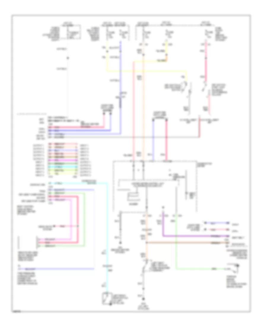
- Unified meter control unit
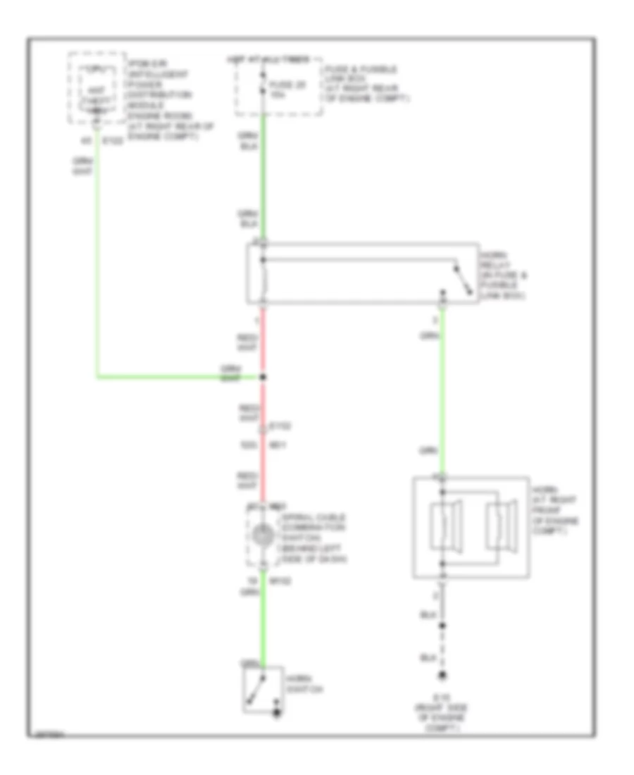
HORN
Horn Wiring Diagram for Nissan Armada SL 2013
List of elements for Horn Wiring Diagram for Nissan Armada SL 2013:
- 52g
- Ant theft hrn
- Cpu
- E122
- E15 (right side of engine compt)
- E152
- Fuse & fusible link box (at right rear of engine compt)
- Fuse 25 15a
- Horn (at right front of engine compt)
- Horn relay (in fuse & fusible link box)
- Horn switch
- Hot at all times
- Ipdm e/r (intelligent power distribution module engine room) (at right rear of engine compt)
- M102
- M30
- M31
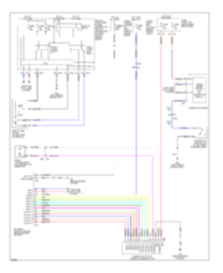
- Spiral cable (combination switch) (behind left side of dash)
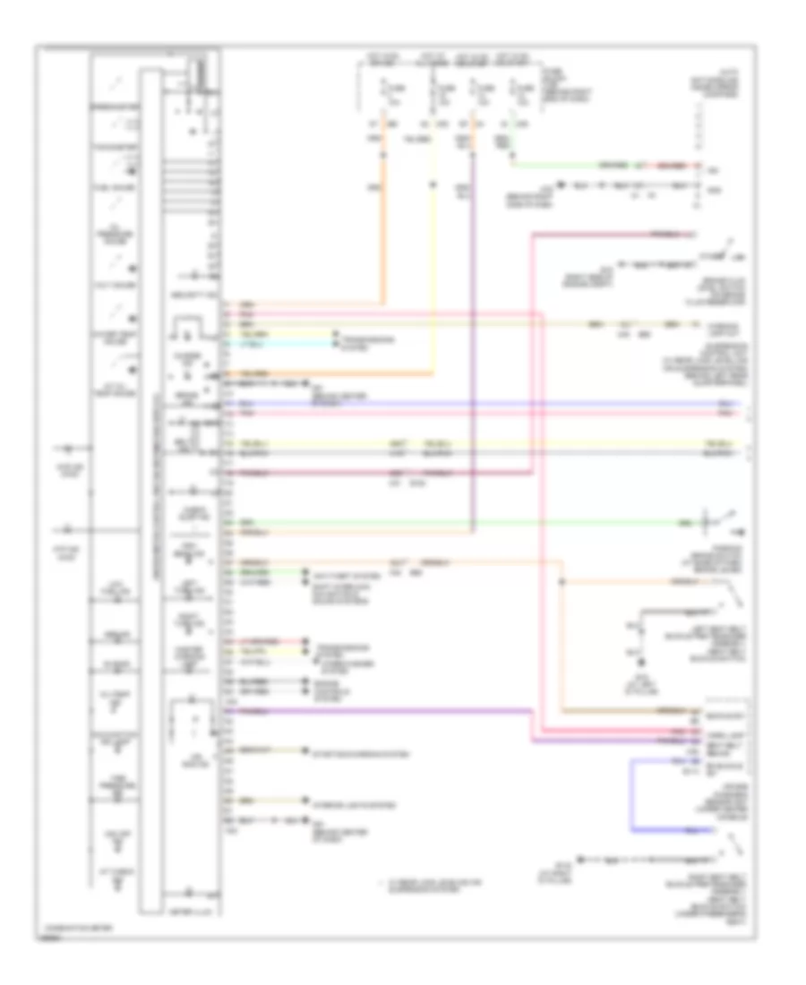
INSTRUMENT CLUSTER
Instrument Cluster Wiring Diagram (1 of 2) for Nissan Armada SL 2013
List of elements for Instrument Cluster Wiring Diagram (1 of 2) for Nissan Armada SL 2013:
- 12j
- 20j
- 41g
- 45g
- 46g
- 4wd ind (4wd)
- A/t check ind
- A/t oil temp gauge
- Abs ind
- Air bag diagnosis sensor unit (under center console)
- Air bag ind
- Anti-theft system
- Atp ind (4wd)
- Auto anti-dazzling inside mirror (compass)
- B113
- B132 (at right "d" pillar)
- B19 (at left "d" pillar)
- B69
- Belt ind
- Brake fluid level switch (on brake fluid reservoir)
- Brake ind
- Buckle sw
- Buzzer
- Charge ind
- Check susp ind
- Combination meter
- E15 (right side of engine compt)
- E152
- Engine controls system
- Fuel gauge
- Fuse 10a
- Fuse block (j/b) (behind right end of dash)
- Gnd
- High beam ind
- Hot at all times
- Hot in on or acc
- Hot in on or start
- Ign
- Interior lights system
- Left seat belt buckle pre-tensioner assembly (seat belt buckle switch)
- Left turn ind
- Low
- Low fuel ind
- M23
- M24
- M31
- M35
- M39
- M40
- M60
- M61 (behind center of dash)
- M79 (behind right side of dash)
- Malfunction ind lamp
- Master warning lamp
- Meter illum
- Oil pressure gauge
- Oil/temp ind
- Other
- Parking brake switch (at base of park brake lever)
- Pnk
- Rh buckle sw
- Right seat belt buckle pre-tensioner assembly (seat belt buckle switch) (under passenger's seat)
- Right turn ind
- Seat belt remind
- Security ind
- Shift interlock, navigation & sound systems
- Slip ind
- Speedometer
- Starting/charging system
- Suspension control unit (w/ rear load levelling air suspension system) (behind left rear quarterpanel)
- Tachometer
- Tire pressure ind
- Transmissions system
- Unified meter control unit (w/ information display)
- Vdc off ind
- Volt gauge
- W/ rear load leveling air suspension system
- Warn lamp
- Warning lamp out
- Water temp gauge
- Wiper/washer system
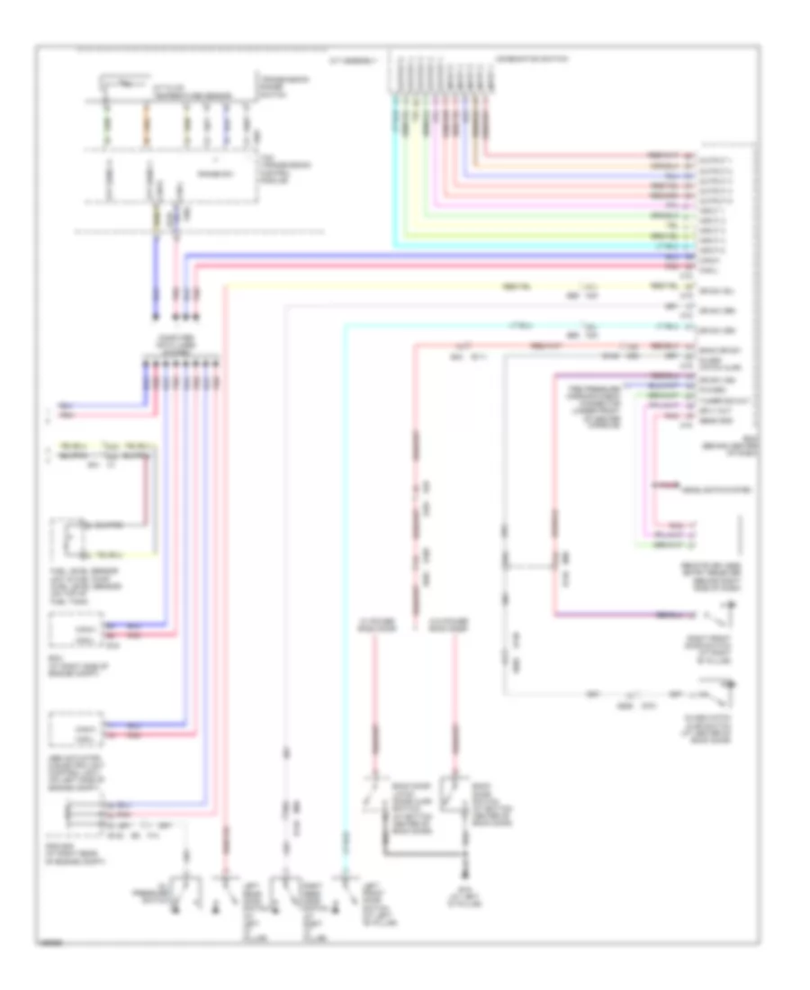
Instrument Cluster Wiring Diagram (2 of 2) for Nissan Armada SL 2013
List of elements for Instrument Cluster Wiring Diagram (2 of 2) for Nissan Armada SL 2013:
- 15a
- 21a
- 21j
- 25a
- 26a
- 30j
- 43c
- 44c
- A/t assembly
- A/t fluid temperature sensor
- Abs actuator & electric unit (control unit) (on left side of engine compt)
- Atf sens 1+
- Atf sens 1-
- B111
- B139
- B149
- B19 (at left "d" pillar)
- B43
- B48
- Back door latch (door ajar switch) (at bottom center of back door)
- Back door switch (at bottom center of back door)
- Back dr sw
- Bcm (behind center of dash)
- Can-h
- Can-l
- Combination switch
- Computer data lines system
- Cpu
- D401
- D405
- D501
- D602
- D606
- D701
- Dr sw (as)
- Dr sw (dr)
- Dr sw (rl)
- Dr sw (rr)
- E122
- E16
- E41 c1
- Ecm (at right side of engine compt)
- F14
- F502
- F503
- Fuel level sensor unit & fuel pump (fuel level sensor) (on top of fuel tank)
- Glass hatch ajar
- Glass hatch ajar switch (at center of back door)
- Headlights system
- Input 1
- Input 2
- Input 3
- Input 4
- Input 5
- Ipdm e/r (at right rear of engine compt)
- Left front door switch (at left "b" pillar)
- Left rear door switch (at left "c" pillar)
- M18
- M19
- M36
- M36 b149
- M40 b69
- Oil pressure switch
- Output 1
- Output 2
- Output 3
- Output 4
- Output 5
- P/warn
- Pnk
- Range sw
- Remote keyless entry receiver (behind right side of dash)
- Right front door switch (at right "b" pillar)
- Right rear door switch (at right "c" pillar)
- Sens gnd
- Sply out
- Tcm (transmission control module)
- Tire pressure warning check connector (under front of center console)
- Transmission range switch
- Tuner sig out
- W/ power back door
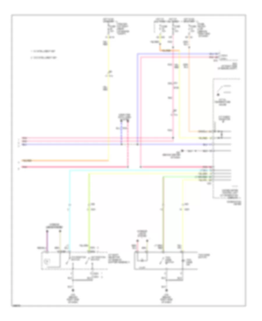
- W/o power back door
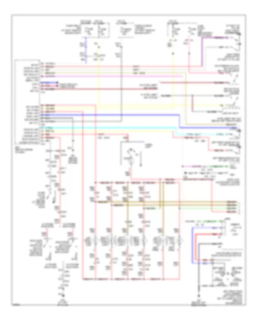
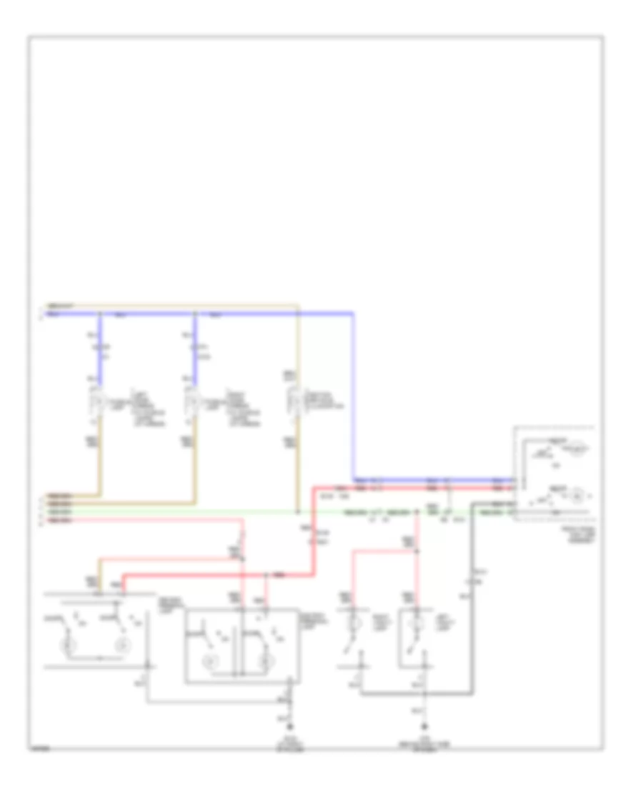
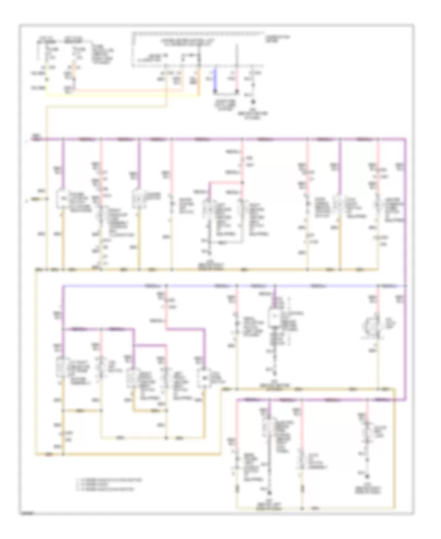
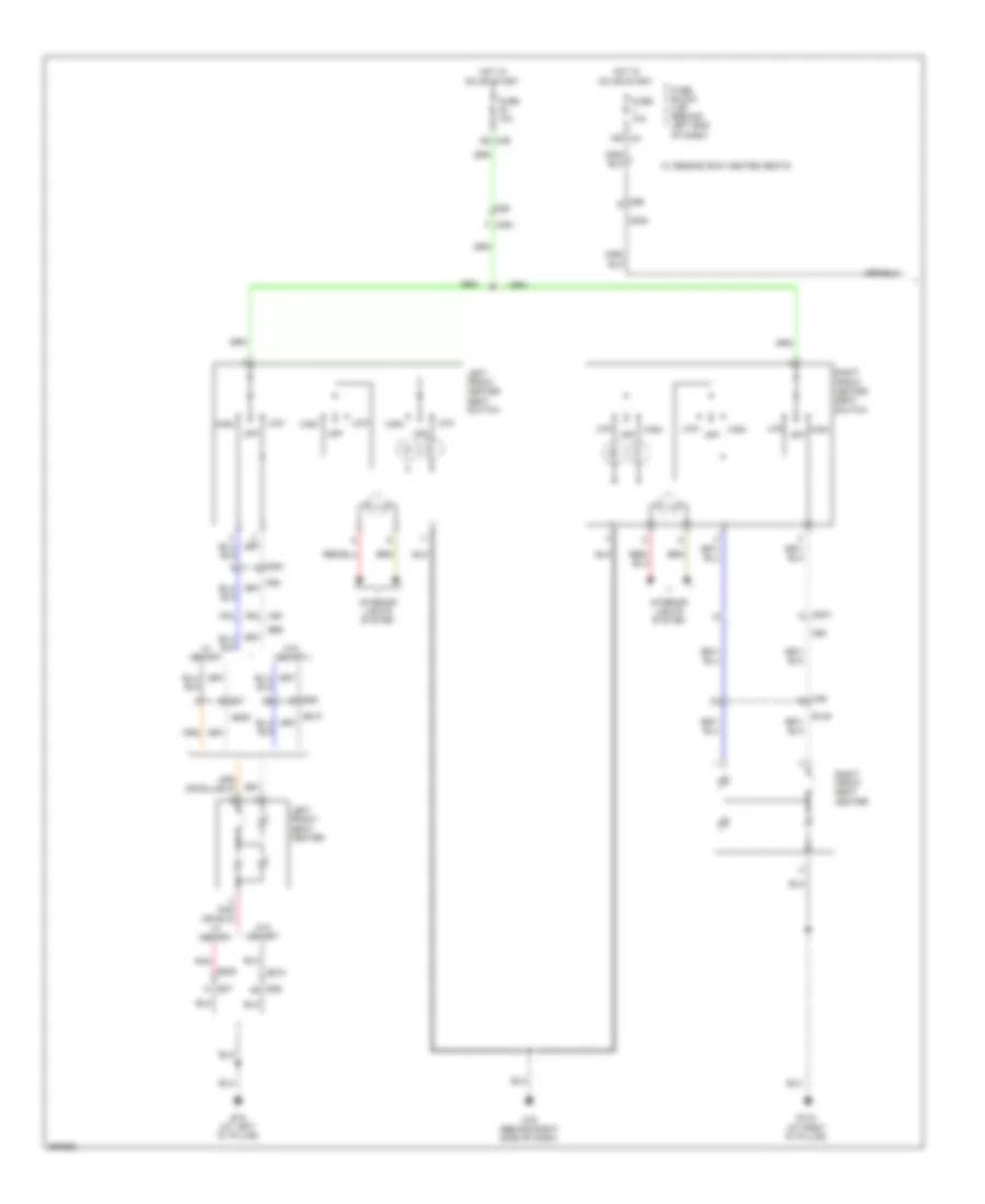
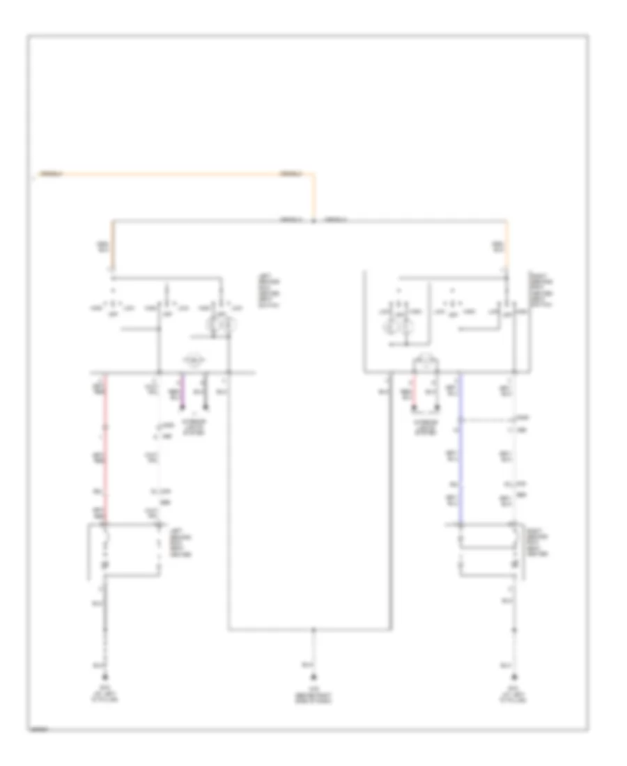
INTERIOR LIGHTS
Courtesy Lamps Wiring Diagram (1 of 2) for Nissan Armada SL 2013
List of elements for Courtesy Lamps Wiring Diagram (1 of 2) for Nissan Armada SL 2013:
- (at right "b" pillar) right front door switch
- (on steering column) key switch & key lock solenoid
- 21a
- 21j
- 25a
- 26a
- 30j
- 77a
- 99g
- Anti pinch
- Anti-pinch serial link
- B106
- B111
- B139
- B149
- B19 (at left "d" pillar)
- B43
- B48
- B69
- Back door latch (door ajar switch) (at bottom center of back door)
- Back door sw
- Back door switch (at bottom center of back door)
- Bat (f/l)
- Bat (fuse)
- Bat saver
- Bcm (behind center of dash)
- Between full stroke & n
- Can-h
- Can-l
- Cargo lamp
- Computer data lines system
- Cpu
- D101
- D102
- D201
- D301
- D401
- D405
- D501
- D602
- D606
- D701
- Door
- Door lock/ unlock right power window & switch
- Door sw (as)
- Door sw (dr)
- Door sw (rl)
- Door sw (rr)
- E152
- Full stroke
- Fuse & fusible link box (at right rear of engine compt)
- Fuse & relay box (at right rear of engine compt)
- Fuse 10a
- Fuse 15a
- Fuse block (j/b) (behind right end of dash)
- Fusible link f 50a
- Glass hatch ajar switch (at center of back door)
- Glass hatch sw
- Gnd
- Gnd (power)
- Hot at all times
- Hot in on or start
- Ign sw
- Intelligent key unit (behind left side of dash)
- Key ring out
- Key sw
- Key sw input
- Key switch & ignition knob switch
- Key system
- Left foot lamp (if equi- pped)
- Left front door lock assembly (left front door key cylinder switch) (rear of driver's door)
- Left front door switch (at left "b" pillar)
- Left front step lamp
- Left rear door switch (at left "c" pillar)
- Left rear step lamp
- Lock
- Lock switch
- Luggage lamp
- M18
- M19
- M20
- M3 1n
- M31 60g
- M36
- M36 14a
- M36 15a
- M36 39a
- M4 13p
- M40
- M40 28j
- M40 29j
- M57 (behind left side of dash)
- M61 (behind center of dash)
- M74
- M75
- M79 (behind right side of dash)
- Main power window & door lock/unlock switch
- Off
- Pnk
- Red
- Right foot lamp (if equi- pped)
- Right front step lamp
- Right rear door switch (at right "c" pillar)
- Right rear step lamp
- Room lamp
- Step lamp
- Unlock
- Unlock switch
- W/ intelligent
- W/ power back door
- W/o intelligent
- W/o power back door
Courtesy Lamps Wiring Diagram (2 of 2) for Nissan Armada SL 2013
List of elements for Courtesy Lamps Wiring Diagram (2 of 2) for Nissan Armada SL 2013:
- 2nd row personal lamp
- 3rd row personal lamp
- 40a
- B132 (at right "d" pillar)
- B146
- B149
- D102
- Door
- Front room/ map lamp assembly
- Ignition keyhole illumination
- Left door mirror (w/ puddle lamps) (at mirror)
- Left vanity lamp
- M36
- M74
- M79 (behind right side of dash)
- Off
- Puddle lamp
- R101
- R201
- Red
- Right door mirror (w/ puddle lamps) (at mirror)
- Right vanity lamp
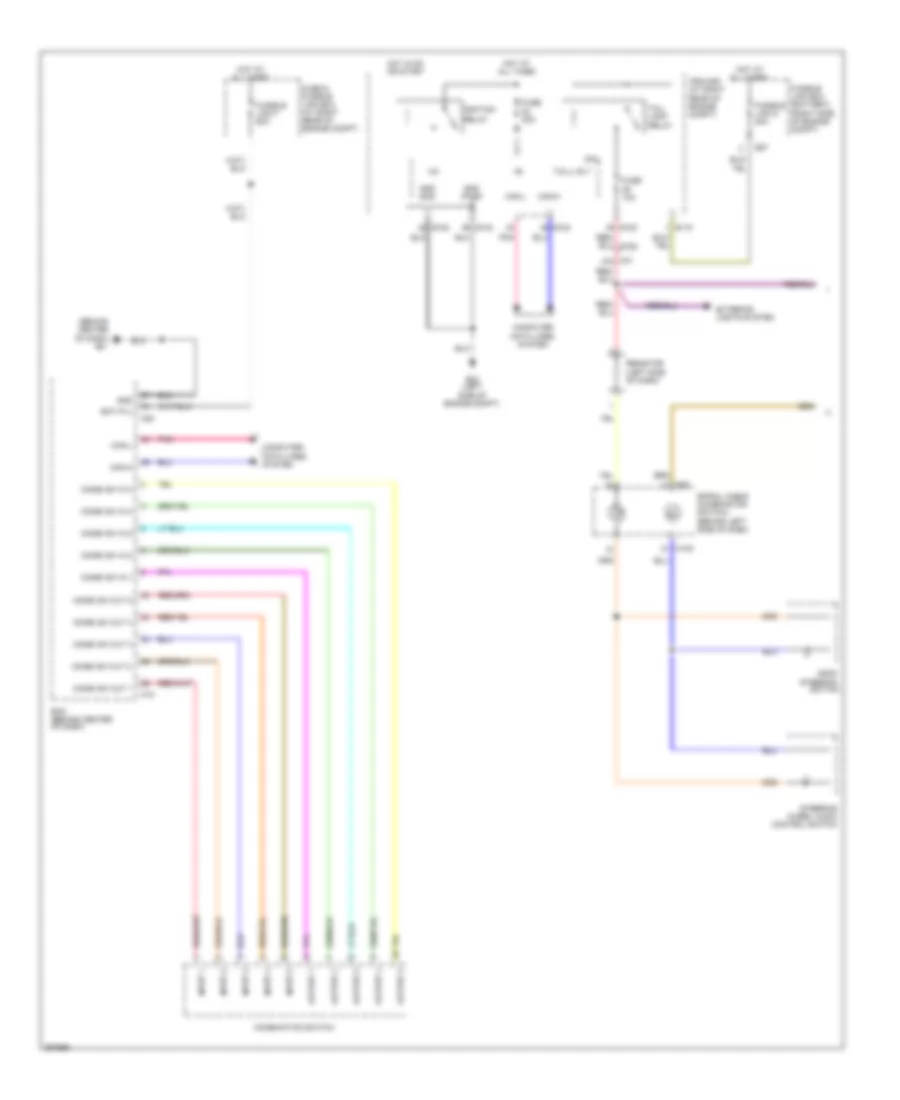
Instrument Illumination Wiring Diagram (1 of 2) for Nissan Armada SL 2013
List of elements for Instrument Illumination Wiring Diagram (1 of 2) for Nissan Armada SL 2013:
- (behind center of dash) m61
- +ig
- Ascd steering switch
- Bat (f/l)
- Bcm (behind center of dash)
- Can-h
- Can-l
- Combi sw in 1
- Combi sw in 2
- Combi sw in 3
- Combi sw in 4
- Combi sw in 5
- Combi sw out 1
- Combi sw out 2
- Combi sw out 3
- Combi sw out 4
- Combi sw out 5
- Combination switch
- Computer data lines system
- Cpu
- E118
- E122
- E123
- E124
- E24 (left side of engine compt)
- E27
- Exterior lights system
- Fuse & fusible link box (at right rear of engine compt)
- Fuse 10a
- Fuse 20a
- Fusible link box (battery) (right side of engine compt)
- Fusible link d 80a
- Fusible link f 50a
- Gnd
- Gnd (pwr)
- Gnd (sig)
- Hot at all times
- Hot in on or start
- Ignition
- Input 1
- Input 2
- Input 3
- Input 4
- Input 5
- Ipdm e/r (at right rear of engine compt)
- M102
- M18
- M20
- M30
- M31 47g
- Output 1
- Output 2
- Output 3
- Output 4
- Output 5
- Pnk
- Relay
- Resistor (left side of dash)
- Spiral cable (combination switch) (behind left side of dash)
- Steering wheel audio control switch
- Tail lamp relay
- Tail/l rly
Instrument Illumination Wiring Diagram (2 of 2) for Nissan Armada SL 2013
List of elements for Instrument Illumination Wiring Diagram (2 of 2) for Nissan Armada SL 2013:
- 4q m39
- 4wd shift switch (if equipped)
- A/c & av switch assembly
- A/c auto amp
- A/t shift selector (at base of shifter assembly)
- Av control unit (behind center of dash)
- Combination meter
- Computer data lines system
- Door mirror remote control switch
- Electric brake (pre- wiring) (behind right kick panel)
- Front room/map lamp assembly (console box illumination)
- Fuse 10a
- Fuse block (j/b) (behind right end of dash)
- Glove box lamp
- Gnd
- Hazard switch
- Heater steering wheel switch (if equipped)
- Hot at all times
- Hot in on or start
- Ill
- Left front heated seat switch (if equipped)
- Left second row heated seat switch (if equipped)
- M158
- M160
- M163
- M165
- M201
- M23
- M24
- M251
- M4 5p
- M42
- M56
- M57 (behind left side of dash)
- M61 (behind center of dash)
- M63
- M79 (behind right side of dash)
- Meter illumination
- Pedal adjusting switch (left side of dash)
- Pnk
- Power liftgate switch (w/ power back door)
- R101
- Rear power vent window switch (if equipped)
- Right front heated seat switch (if equipped)
- Right second row heated seat switch (if equipped)
- Sonar system off switch
- Tow mode switch
- Unified meter control unit (w/ information display)
- Vdc off switch
- W/ base audio
- W/ bose audio & navigation
- W/ bose audio & w/o navigation
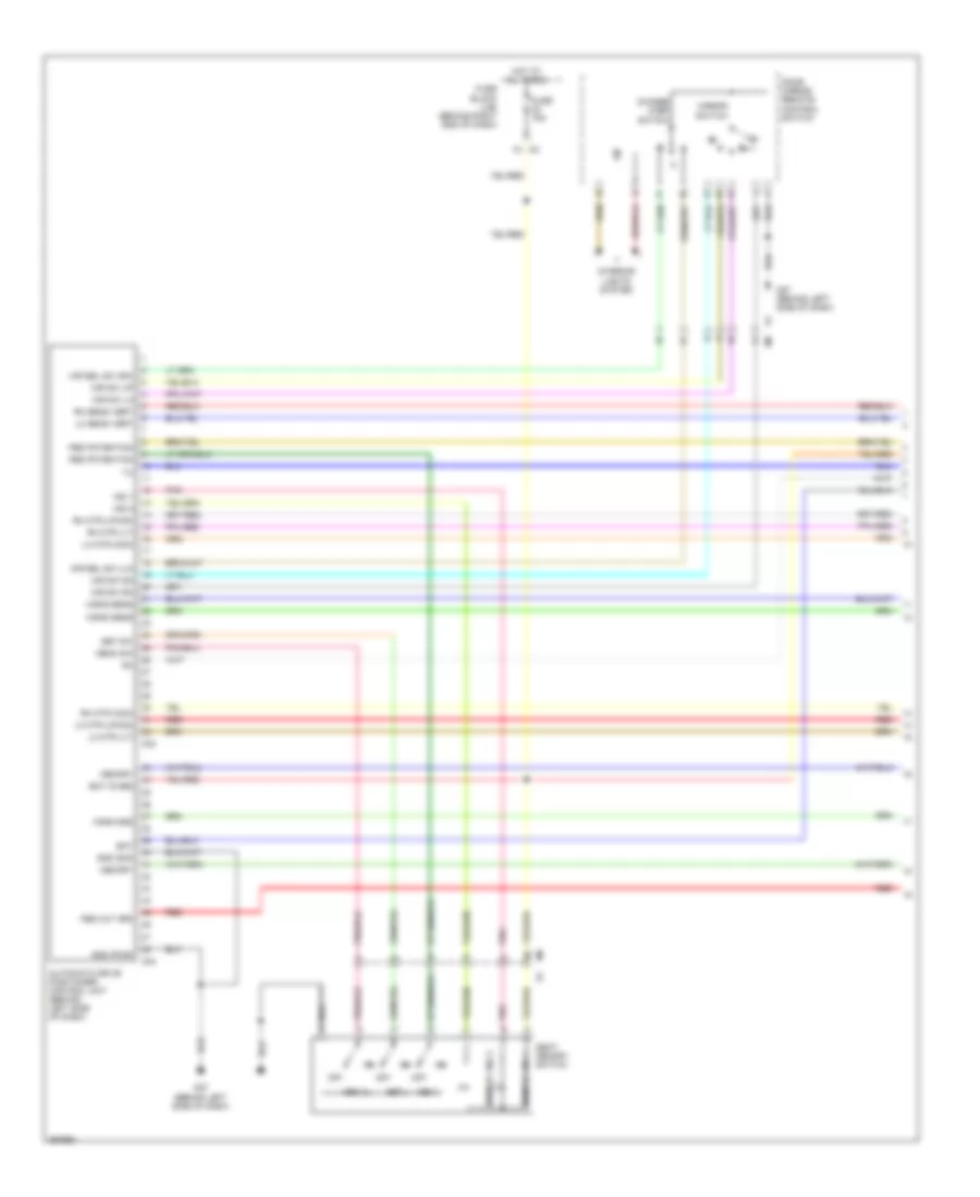
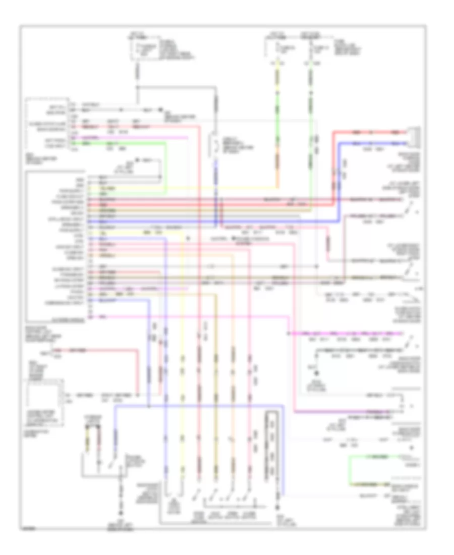
MEMORY SYSTEMS
Memory Systems Wiring Diagram (1 of 3) for Nissan Armada SL 2013
List of elements for Memory Systems Wiring Diagram (1 of 3) for Nissan Armada SL 2013:
- 1n m3
- Automatic drive positioner control unit (behind left side of dash)
- Bat
- Bat (fuse)
- Change over switch
- Door mirror remote control switch
- Forward
- Fuse 15a
- Fuse block (j/b) (behind right end of dash)
- Gnd (pwr)
- Gnd (sig)
- Horiz sens
- Hot at all times
- Ind 1
- Ind 2
- Interior lights system
- Lh mtr (com)
- Lh mtr (lt)
- Lh mtr (up-dn)
- Lh sens vert
- M33
- M34
- M57 (behind left side of dash)
- Mem 1
- Mem 2
- Memo sw
- Memory
- Memory ind 1
- Memory ind 2
- Mir sel sw (lh)
- Mir sel sw (rh)
- Mir sw dn
- Mir sw lh
- Mir sw rh
- Mir sw up
- Mirror switch
- Off
- Ped out (rr)
- Ped potention
- Pnk
- R l
- Red
- Rh mtr (com)
- Rh mtr (lt)
- Rh mtr (up-dn)
- Rh sens vert
- Seat memory switch
- Set
- Set sw
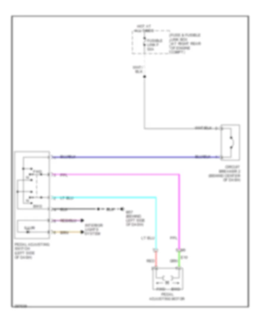
Memory Systems Wiring Diagram (2 of 3) for Nissan Armada SL 2013
List of elements for Memory Systems Wiring Diagram (2 of 3) for Nissan Armada SL 2013:
- (at mirror) right door mirror
- 46j
- 47j
- A/t shift selector (at base of shifter assembly)
- B69
- Bwd
- Can-h
- Can-l
- Computer data lines system
- D102
- Defogger system
- E10 m6
- E109
- E110
- Fuse & relay box (at right rear of engine compt)
- Fuse 10a
- Fwd
- Hot at all times
- Intelligent key unit (behind left side of dash)
- Interior lights system
- Key switch & ignition knob switch
- Left door mirror (at mirror)
- M201 m56
- M40
- M57 (behind left side of dash)
- M74
- Pedal adjusting motor assembly
- Pedal adjusting switch (left side of dash)
- Pnk
- Pu sw in
- Red
Memory Systems Wiring Diagram (3 of 3) for Nissan Armada SL 2013
List of elements for Memory Systems Wiring Diagram (3 of 3) for Nissan Armada SL 2013:
- (behind center of dash) m61
- (or red)
- 14p
- 30j
- 34j
- 35j
- 36j
- 37j
- 45j m40
- 91j
- 99g m31
- Acc sw
- B19 (at left "d" pillar)
- B200
- B202
- B203
- B37
- B69
- B7 (under driver's seat)
- Backward
- Bat (f/l)
- Bat (fuse)
- Bat (ptc)
- Bcm (body control module) (behind center of dash)
- Bwd
- Can-h
- Can-l
- Circuit breaker-2 (behind center of dash)
- Computer data lines system
- Door sw (dr)
- Down
- Driver seat control unit (under driver's seat)
- E152
- Forward
- Fr lifter dn mtr
- Fr lifter up mtr
- Fr lifter up sw
- Front lift dn sw
- Front lifting motor (under driver's seat)
- Fuse & fusible link box (at right rear of engine compt)
- Fuse & relay box (at right rear of engine compt)
- Fuse 10a
- Fuse block (j/b) (behind right end of dash)
- Fusible link f 50a
- Fwd
- Gnd (pwr)
- Gnd (sensor gnd)
- Gnd (signal)
- Hot at all times
- Hot in on or acc
- Hot in on or start
- Ign sw
- Left front door switch (at left "b" pillar)
- Left power seat switch
- Left reclining motor (under driver's seat)
- Left sliding motor (under driver's seat)
- Lifting switch (front)
- Lifting switch (rear)
- M18
- M19
- M20
- M40
- M60
- P range sw
- Pedal back
- Pedal forward sw
- Pnk
- Pulse (recliner)
- Pulse (rr lifter)
- Pulse (slide)
- Pulse fr lifting
- Rear lift dn sw
- Rear lifting motor (under driver's seat)
- Recline backwd mtr
- Recline backwd sw
- Recline fwd sw
- Reclining fwd mtr
- Reclining switch
- Red
- Rr lifter dn mtr
- Rr lifter up mtr
- Rr lifter up sw
- Rx (uart)
- Slide backwd mtr
- Slide backwd sw
- Slide fwd sw
- Sliding fwd mtr
- Sliding switch
- St sw
- Tx (uart)
NAVIGATION
Front & Rear Sonar Wiring Diagram (1 of 2) for Nissan Armada SL 2013
List of elements for Front & Rear Sonar Wiring Diagram (1 of 2) for Nissan Armada SL 2013:
- 22c
- 23c
- 38c
- 39c
- 40c
- 41c
- 64g
- 94g m31
- A/t assembly
- B19 (at left "d" pillar)
- B40
- B41
- B56
- B57
- B69
- Backup light relay (behind center of dash)
- C101
- Computer data lines system
- Disable sw
- E119
- E152
- E34
- E35
- E35 b41
- E41
- Exterior lights system
- F14
- F502
- Fil
- Fir
- Fol
- For
- Fr sounder (-)
- Fuse 10a
- Fuse block (j/b) (behind right end of dash)
- Gnd
- Hot in on or start
- Ign
- Ipdm e/r (at right rear of engine compt)
- K-line
- Led status
- Left inner rear sonar sensor (at inner left side of rear bumper)
- Left outer rear sonar sensor (at outer left side of rear bumper)
- M39 1q
- M40 17j
- Park-pos
- Pnk
- Pwr
- Red
- Rev lamp rly
- Rev lmp sig
- Right inner rear sonar sensor (at inner right side of rear bumper)
- Right outer rear sonar sensor (at outer right side of rear bumper)
- Ril
- Rir
- Rol
- Ror
- Rr sounder (+)
- Rr sounder (-)
- Sonar control unit (behind left rear quarterpanel)
- Tcm (transmission control module)
- Vehicle speed
Front & Rear Sonar Wiring Diagram (2 of 2) for Nissan Armada SL 2013
List of elements for Front & Rear Sonar Wiring Diagram (2 of 2) for Nissan Armada SL 2013:
- 15j
- 18j
- 19j
- 20a
- 27j
- 30a
- B111
- B149
- B43
- B69
- Combination meter
- E159
- E160
- E164
- E165
- Front sonar buzzer (left side of dash)
- Illumination
- Interior lights system
- Left inner front sonar sensor (at inner left side of rear bumper)
- Left outer front sonar sensor (at outer left side of rear bumper)
- M24
- M36
- M40
- M57 (behind left side of dash)
- Off indicator
- Off switch
- Pnk
- Rear sonar buzzer (center rear of roof)
- Red
- Right inner front sonar sensor (at inner right side of rear bumper)
- Right outer front sonar sensor (at outer right side of rear bumper)
- Sonar system off switch
- Unified meter control unit (w/ information display)
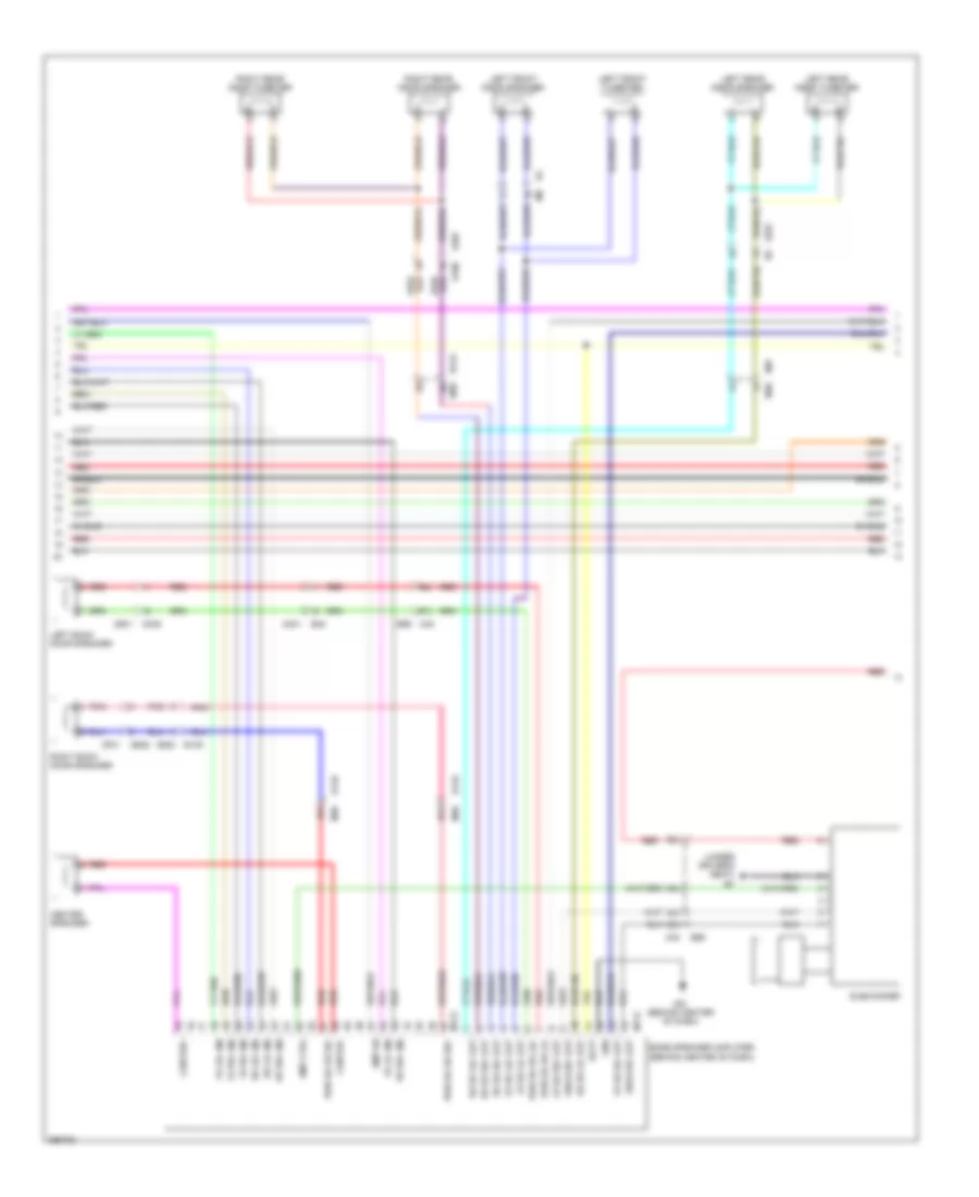
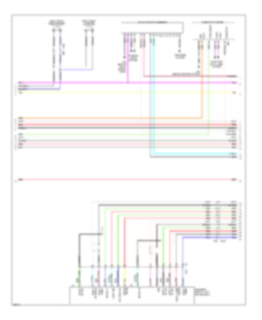
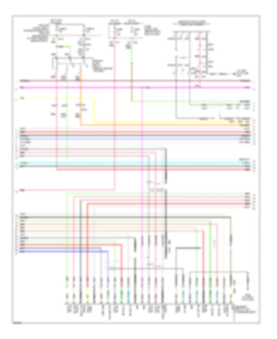
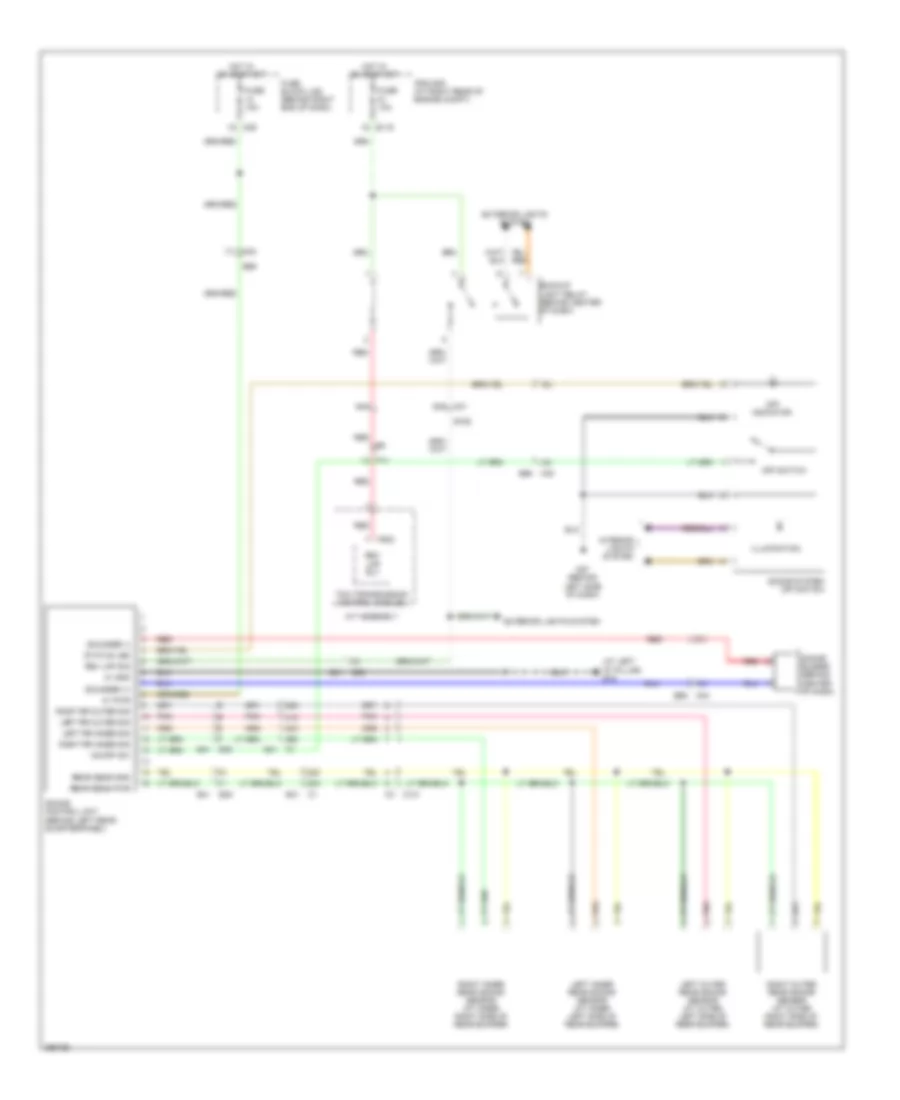
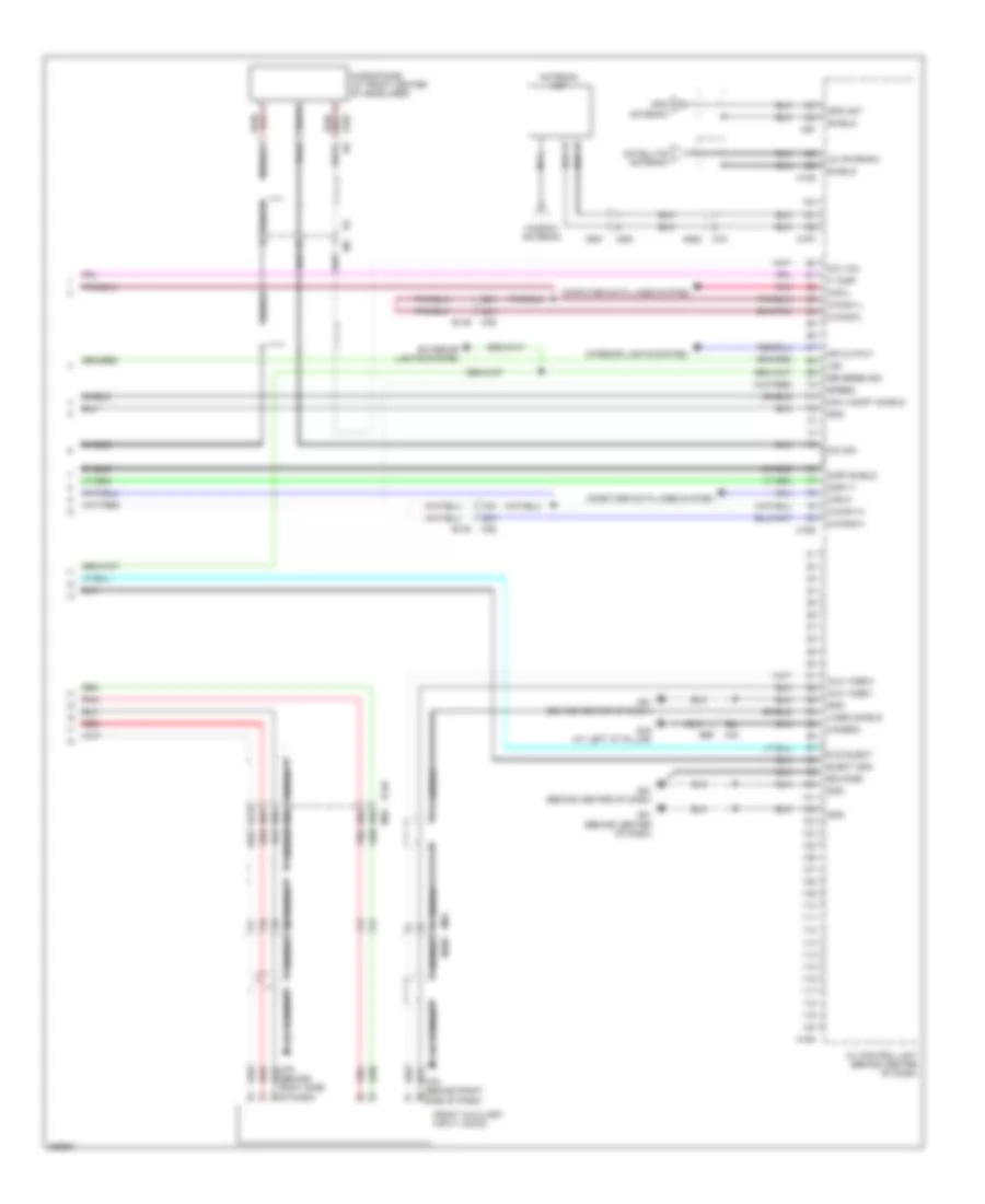
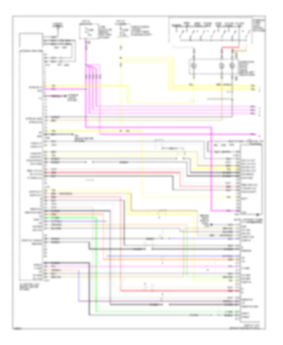
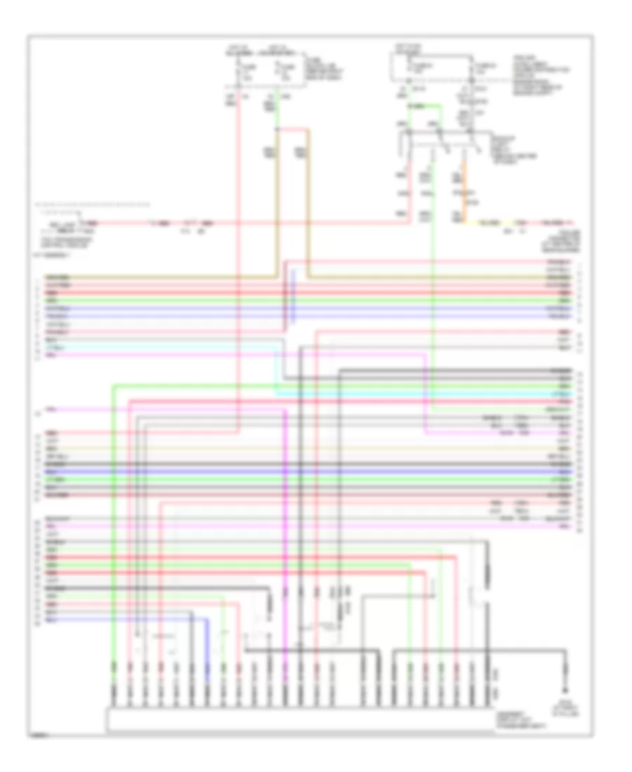
Navigation Wiring Diagram (1 of 6) for Nissan Armada SL 2013
List of elements for Navigation Wiring Diagram (1 of 6) for Nissan Armada SL 2013:
- 91g
- Acc
- Amp on
- Aux audio lh
- Aux audio rh
- Aux audio-
- Aux shield
- Av control unit (behind center of dash)
- Back
- Combination switch (spiral cable) (behind left side of dash)
- E152
- Enter
- Fr lh pre+
- Fr lh pre-
- Fr rh pre+
- Fr rh pre-
- Fuse & fusible link box (at right rear of engine compt)
- Fuse 10a
- Fuse 20a
- Fuse block (j/b) (behind right end of dash)
- Gnd
- Hot at all times
- Hot in on or acc
- M102
- M161
- M165
- M177
- M30
- M31
- M60
- M61 (behind center of dash)
- M79 (behind right side of dash)
- Menu down
- Menu up
- Mic gnd
- Navi comp 1+
- Navi comp 1-
- Nca
- Phone
- Pkb sig
- Red
- Rr lh pre+
- Rr lh pre-
- Rr rh pre+
- Rr rh pre-
- Shield
- Source
- Steering wheel audio control switches
- Strg sw a
- Strg sw b
- Strg sw gnd
- Volume down
- Volume up
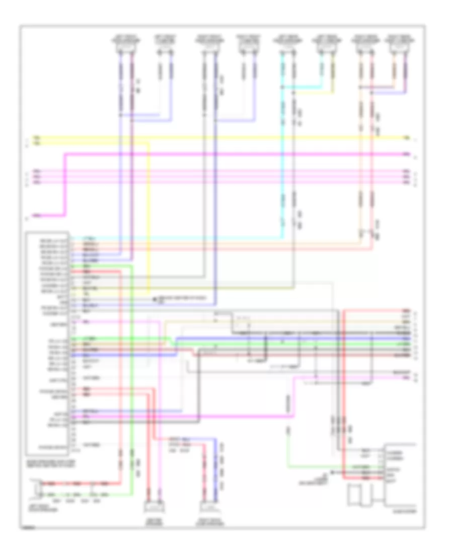
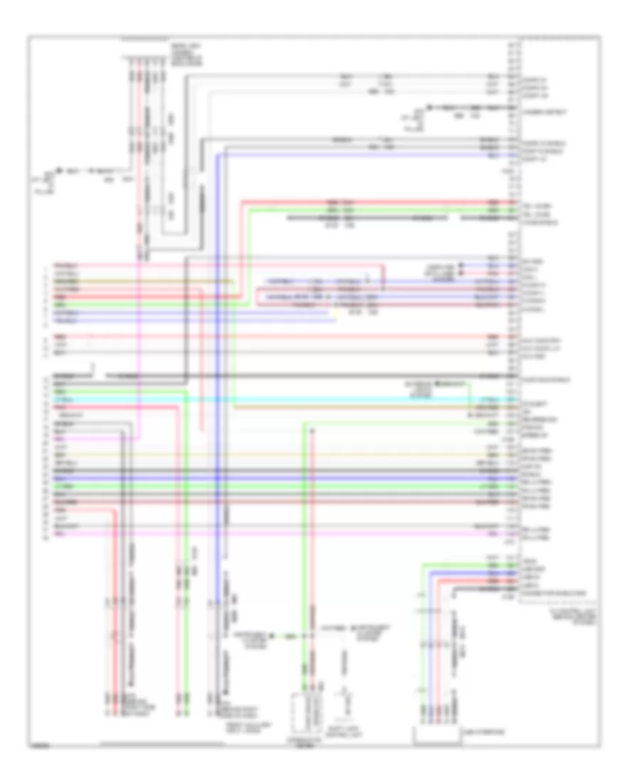
Navigation Wiring Diagram (2 of 6) for Nissan Armada SL 2013
List of elements for Navigation Wiring Diagram (2 of 6) for Nissan Armada SL 2013:
- (under driver's seat) b7
- 24j
- 25j
- 45a
- 57a
- 57j
- 58j
- 59j
- 96j
- Amp ctrl
- Amp on
- B106
- B139 d602
- B149
- B149 m36
- B48 d401
- B69
- B69 m40
- Batt
- Bose speaker amplifier (behind center of dash)
- Center speaker
- Center+
- Center-
- D2 m8
- D201 b6
- D301
- D405 d501
- D606
- D701
- Fr dr lh+ out
- Fr dr lh- out
- Fr dr rh+ out
- Fr dr rh- out
- Fr lh+ (in)
- Fr lh- (in)
- Fr rh+ (in)
- Fr rh- (in)
- Gnd
- Left back door speaker
- Left front door speaker
- Left front tweeter
- Left rear door speaker
- Left rear door tweeter
- M112
- M113
- M36
- M40
- M40 b69
- M61 (behind center of dash)
- Pnk
- Pwr bk dr lh+
- Pwr bk dr lh-
- Pwr bk dr rh+
- Pwr bk dr rh-
- Red
- Right back door speaker
- Right rear door speaker
- Right rear door tweeter
- Rr dr lh+ out
- Rr dr lh- out
- Rr dr rh+ out
- Rr dr rh- out
- Rr lh+ (in)
- Rr lh- (in)
- Rr rh+ (in)
- Shield
- Subwoofer
- Woofer+ out
- Woofer- out
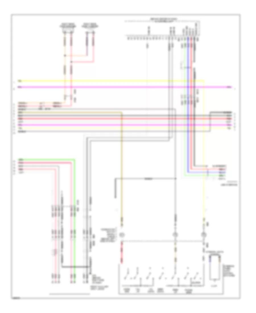
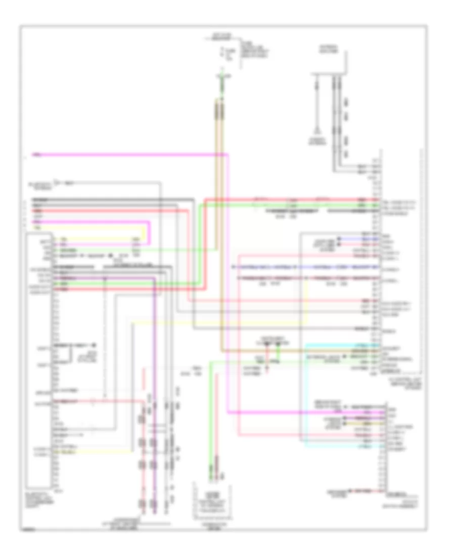
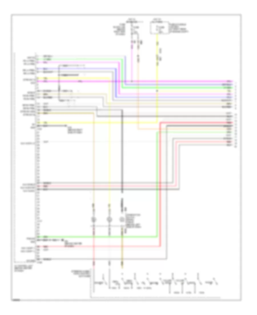
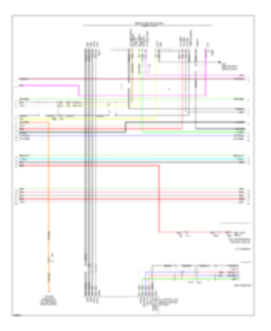
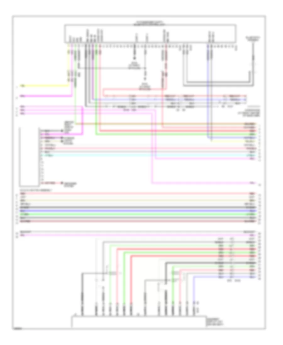
Navigation Wiring Diagram (3 of 6) for Nissan Armada SL 2013
List of elements for Navigation Wiring Diagram (3 of 6) for Nissan Armada SL 2013:
- A/c & av switch assembly
- Aux req out
- B125
- B217
- B79
- Batt
- Can-h
- Can-l
- Combination meter
- Comp -
- Comp+
- Computer data lines system
- Cont gnd
- D101 m75
- Defogger system
- Gnd
- Headrest display unit (driver seat)
- Hp lh+
- Hp lrh-
- Hp rh+
- Hp shield
- Interior lights system
- M-can
- M-can 1 l
- M-can 2 h
- M24
- M61 (behind center of dash)
- M79 (behind right side of dash)
- Park brake
- Pnk
- Rear 1
- Rear 1 comp
- Red
- Right front door speaker
- Right front tweeter
- Shield
- Speed out
Navigation Wiring Diagram (4 of 6) for Nissan Armada SL 2013
List of elements for Navigation Wiring Diagram (4 of 6) for Nissan Armada SL 2013:
- (at left "d" pillar) b19
- (center of back door) rear view camera
- 16p
- 51a
- 52a
- 53a
- 54a
- 64a
- 64g
- 69j
- 94g
- 97g m31
- Acc det in
- Aux req out
- Av gnd
- B104
- B132 (at right "d" pillar)
- B149
- B304
- B48
- Backup light relay (behind center of dash)
- Bat
- Comp -
- Comp+
- Cont gnd
- D401
- D405
- D501
- E119
- E121
- E152
- Fuse 10a
- Fuse 38 10a
- Fuse 51 10a
- Fuse block (j/b) (behind right end of dash)
- Gnd
- Headrest display unit (passenger seat)
- Hot at all times
- Hot in on or start
- Hp lh+
- Hp lh-
- Hp lrh-
- Hp rh+
- Hp shield
- Ipdm e/r (intelligent power distribution module engine room) (at right rear of engine compt)
- M-can
- M-can 1 h
- M-can 1 l
- M-can 2 h
- M-can 2 l
- M31
- M36
- M39
- M40
- Nca
- Pnk
- Rear 1
- Rear 1 comp
- Rear 1 hp
- Red
- Red b69
- Shield
Navigation Wiring Diagram (5 of 6) for Nissan Armada SL 2013
List of elements for Navigation Wiring Diagram (5 of 6) for Nissan Armada SL 2013:
- (behind center of dash) display unit
- (or red)
- 54j
- 66j
- 67j
- A/t assembly
- Acc
- Av control unit (behind center of dash)
- B69
- Batt
- Comp in shield
- E41
- F14
- F502
- Fr comp shield rr camera- comp in-
- Fr comp+
- Fr comp-
- Fr disp it comp in+
- Fr sync
- Gnd
- Gvif+
- Gvif-
- It front disp
- M115
- M130
- M131
- M168
- M173 shield gnd connector
- M213
- M40
- M79 (behind right side of dash)
- Pnk
- Red
- Red rev lamp relay
- Rr camera-
- Shield
- Tcm (transmission control module)
- Trailer connector (at center of rear bumper)
- Usb d+
- Usb d-
- Usb gnd
- Usb interface
- Vbus
Navigation Wiring Diagram (6 of 6) for Nissan Armada SL 2013
List of elements for Navigation Wiring Diagram (6 of 6) for Nissan Armada SL 2013:
- 18a
- 23a
- 24a
- 28a
- 62j
- 65a
- 66a
- 67a
- 68a
- 69a
- 70a
- Antenna amp
- Aux video+
- Aux video-
- Av control unit (behind center of dash)
- B149
- B19 (at left "d" pillar)
- B69
- Camera
- Can-h
- Can-l
- Computer data lines system
- Disp it
- Disp shield
- Dvd eject
- Eject gnd
- Eq mode
- Exterior lights system
- Front auxiliary input jacks
- Gnd
- Gps ant
- Gps antenna
- Ign
- Interior lights system
- It disp
- M-can1-h
- M-can1-l
- M-can2-h
- M-can2-l
- M125
- M163
- M165
- M167
- M36
- M40
- M550
- M551
- M601
- M61 (behind center of dash)
- M69 m208
- M78
- M79 (behind right side of dash)
- M97
- Mic sig
- Mic vcc
- Microphone (at front center of headliner)
- Mr output
- Navi comp1 shield
- Nca
- Pnk
- R107
- Red
- Reverse sig
- Satellite antenna
- Shield
- Speed
- Video shield
- Window antenna
- Xm antenna
Rear Sonar Wiring Diagram for Nissan Armada SL 2013
List of elements for Rear Sonar Wiring Diagram for Nissan Armada SL 2013:
- (at left "d" pillar) b19
- 15j
- 17j m40
- 18j
- 19j
- 1q m39
- 22c
- 23c
- 27j
- 38c
- 39c
- 40c
- 41c
- 64g
- 94g m31
- A/t assembly
- A1 gnd
- A1 pwr
- B41
- B69
- Backup light relay (behind center of dash)
- C101
- E119
- E152
- E35
- E41
- Exterior lights system
- F14
- F502
- Fuse 10a
- Fuse block (j/b) (behind right end of dash)
- Hot in on or start
- Illumination
- Interior lights system
- Ipdm e/r (at right rear of engine compt)
- Left inner rear sonar sensor (at inner left side of rear bumper)
- Left outer rear sonar sensor (at outer left side of rear bumper)
- Left rr inner sig
- Left rr outer sig
- M40
- M57 (behind left side of dash)
- Off indicator
- Off switch
- On/off sw
- Pnk
- Rear sens gnd
- Rear sens pwr
- Red
- Rev lmp rly
- Rev lmp sig
- Right inner rear sonar sensor (at inner right side of rear bumper)
- Right outer rear sonar sensor (at outer right side of rear bumper)
- Right rr inner sig
- Right rr outer sig
- Sonar buzzer (behind center of dash)
- Sonar control unit (behind left rear quarterpanel)
- Sonar system off switch
- Sounder (+)
- Sounder (-)
- Status led
- Tcm (transmission control module)
POWER DISTRIBUTION
Power Distribution Wiring Diagram (1 of 2) for Nissan Armada SL 2013
List of elements for Power Distribution Wiring Diagram (1 of 2) for Nissan Armada SL 2013:
- (at right rear of engine compt) fuse & fusible link box
- (at right rear of engine compt) ipdm e/r
- 10g
- 96g
- A/c relay
- Air conditioning system
- Anti-lock brakes system
- Anti-theft, horns & door locks systems
- B117 (under front passenger's seat)
- B42
- B43
- Battery
- Canada
- Circuit breaker-2 (behind center of dash)
- Computer data lines system
- Cooling fan relay
- Cpu
- Defogger system
- Defogger, power windows, exterior lights, interior lights, headlights, memory, warning, seats, door locks, anti-theft, power tops, wiper/washer & trunk, tailgate, fuel doors systems
- E118
- E119
- E120
- E121
- E122
- E123
- E124
- E152
- E27
- E33
- Ecm relay
- Electronic suspension system
- Engine controls system
- Exterior lights system
- From fuel pump relay (diagram 2 of 2)
- From fusible link n (diagram 1 of 2)
- Front fog lamp relay (if equipped)
- Front wiper high relay
- Front wiper relay
- Fuse & relay box (at right rear of engine compt)
- Fuse (w/ 4wd) 10a
- Fuse 10a
- Fuse 15a
- Fuse 20a
- Fuse 30a
- Fusible link 100a
- Fusible link a 140a
- Fusible link b 60a
- Fusible link box (battery) (right side of engine compt)
- Fusible link c 80a
- Fusible link d 80a
- Fusible link e 100a
- Fusible link f 50a
- Fusible link g 30a
- Fusible link h 30a
- Fusible link i 40a
- Fusible link j 30a
- Fusible link k (w/ trailer tow) 40a
- Fusible link l 40a
- Fusible link m 40a
- Fusible link n 25a
- Headlights system
- Heated mirror relay
- Interior lights & exterior lights systems
- Interior lights, exterior lights & headlights systems
- Ipdm e/r (at right rear of engine compt)
- M31
- M66
- Navigation & sound systems
- Nca
- Pnk
- Rear cargo power socket
- Red
- Seats, memory & trunk, tailgate, fuel doors systems
- Starting/ charging system
- Tail lamp relay
- Throttle control motor relay
- To fuse & relay box (diagram 2 of 2)
- To fuse 47 (diagram 2 of 2)
- To fuse block (j/b) (diagram 2 of 2)
- To headlamp low relay (diagram 2 of 2)
- To heated mirror relay (diagram 1 of 2)
- To ignition relay (diagram 2 of 2)
- To ignition switch (diagram 2 of 2)
- Transmissions system
- Transmissions, engine controls & anti-theft systems
- W/ 4wd
- W/ heated steering wheel
- W/ intelligent key
- W/ trailer tow
- Wiper/ washer system
Power Distribution Wiring Diagram (2 of 2) for Nissan Armada SL 2013
List of elements for Power Distribution Wiring Diagram (2 of 2) for Nissan Armada SL 2013:
- (at right rear of engine compt) ipdm e/r
- (behind right end of dash) fuse block (j/b)
- (diagram 1 of 2)
- 10p
- 13p m4
- 14p
- 15p m4
- 16p m4
- 1n m3
- 1q m39
- 1r m38
- 1s m37
- 1t m60
- 2n m3
- 2q m39
- 2r m38
- 3n m3
- 3q m39
- 4p m4
- 4q m39
- 5n m3
- 5p m4
- 5q m39
- 6t m60
- 7p m4
- 7q m39
- 9p m4
- Acc
- Acce- ssory relay 2
- Accessory relay
- Air condi- tioning system
- Air conditioning system
- Anti-lock brakes system
- Anti-theft, power tops & interior lights systems
- Console power socket
- Cpu
- Defogger system
- Door locks, anti-theft, interior lights & warning systems shift-interlock, memory & body computer systems
- E119
- E121
- E122
- E123
- E124
- E15 (right side of engine compt)
- E152
- E24 (left side of engine compt)
- Electronic suspension, transmissions, sound, door locks, engine controls, instrument cluster, shift interlock, seats, navigation, trunk, tailgate, fuel doors, computer data lines & mirrors systems
- Engine controls system
- Engine controls, exterior lights, anti-lock brakes, instrument cluster, transmissions & shift interlock systems
- Exterior lights system
- Exterior lights, headlights, door locks,
- Exterior lights, transmissions, navigation & sound systems
- From a/c relay k (diagram 1 of 2)
- From fuse & fusible link box l (diagram 1 of 2)
- From fuse & fusible m
- From fuse & relay box (diagram 2 of 2)
- From fuse 43 (diagram 1 of 2)
- From fuse 52 (diagram 1 of 2)
- From fuse 53 (diagram 1 of 2)
- From fusible link box (battery) (diagram 1 of 2)
- From fusible link f j (diagram 1 of 2)
- From fusible link m b
- Fuel pump relay
- Fuse & relay box (at right rear of engine compt)
- Fuse 10a
- Fuse 15a
- Fuse 20a
- Headlamp high relay
- Headlamp low relay
- Headlights system
- Ig2 red
- Ignition relay
- Ignition switch
- Interior lights, memory, door locks, anti-theft & trunk, tailgate, fuel doors systems
- Left front power socket
- Link box (diagram 1 of 2)
- M201
- M31
- M31 8g
- M31 9g
- M31 e152
- M56
- M79 (behind right side of dash)
- Memory systems
- Mirrors system
- Off
- Pnk
- Rear blower motor relay
- Rear window defogger relay
- Red
- Right front power socket (for cigarette lighter)
- Seats system
- Seats systems
- Sound & navigation systems
- Start
- Starting/ charging system
- To a/c relay (diagram 1 of 2)
- To accessory relay2 (diagram 2 of 2)
- To front wiper high relay (diagram 1 of 2)
- To ignition switch (diagram 2 of 2)
- To ipdm e/r (diagram 2 of 2)
- Transmissions system
- Transmissions, air conditioning, engine controls, seats, mirrors, door locks, anti-theft & computer data lines systems
- Transmissions, door locks, electronic suspension, anti-theft, warning, anti-lock brakes, exterior lights, interior lights, instrument cluster & shift interlock systems
- W/ heated steering wheel
- W/ intelligent key
- W/ trailer tow
- Wiper/ washer system
- Wiper/washer system
- Wiper/washer, warning, power windows, transmissions, engine controls, starting/charging,
POWER DOOR LOCKS
Power Door Locks Wiring Diagram, with Intelligent Key Unit (1 of 3) for Nissan Armada SL 2013
List of elements for Power Door Locks Wiring Diagram, with Intelligent Key Unit (1 of 3) for Nissan Armada SL 2013:
- 15a
- 21a m36
- 21j m40
- 26a
- 30j
- 4q m39
- 6t m60
- Acc sw
- Anti-pinch serial link
- B111 b43
- B149
- B19 (at left "d" pillar)
- B48
- B48 d401
- B69
- Back door latch (door ajar switch) (at bottom center of back door)
- Back door sw
- Bat (f/l)
- Bat (fuse)
- Bat saver output
- Bcm (body control module) (behind center of dash)
- Can-h
- Can-l
- Closed
- Computer data lines system
- D401
- D405
- D405 d501
- Door lock output (all)
- Door sw (as)
- Door sw (dr)
- Door sw (rl)
- Door sw (rr)
- Door unlock output
- Door unlock output (dr)
- E152
- Exterior lights system
- Flasher output (left)
- Flasher output (right)
- Fuse & fusible link box (at right rear of engine compt)
- Fuse & relay box (at right rear of engine compt)
- Fuse 10a
- Fuse 15a
- Fuse block (j/b) (behind right end of dash)
- Fusible link f 50a
- Gnd (power)
- Hot at all times
- Hot in acc or on
- Hot in on or start
- Ign
- Ignition knob switch
- Interior lights system
- Key sw
- Key switch
- Key switch & ignition knob switch (on steering column)
- Left front door switch (at left "b" pillar)
- Left rear door switch (at left "c" pillar)
- M18
- M19
- M20
- M3 1n
- M31 60g
- M31 99g
- M36 b149
- M61 (behind center of dash)
- Open
- Passenger select unlock relay (left end of dash)
- Pnk
- Power windows system
- Right front door switch (at right "b" pillar)
- Right rear door switch (at right "c" pillar)
- Room lamp output
- Step lamp output
Power Door Locks Wiring Diagram, with Intelligent Key Unit (2 of 3) for Nissan Armada SL 2013
List of elements for Power Door Locks Wiring Diagram, with Intelligent Key Unit (2 of 3) for Nissan Armada SL 2013:
- (at rear of left rear door) left rear door lock actuator
- (at rear of right rear door) right rear door lock actuator
- (behind left side of dash) m57
- (rear of front passenger's door) right front door lock actuator
- +ig
- 100a
- 8j m40
- 9a m36
- Actuator lock door
- Anti pinch serial link
- Anti-pinch serial link
- B106
- B149
- B69
- Between full stroke & n
- Can-h
- Can-l
- Computer data lines system
- Cpu
- D101
- D102
- D201
- D301
- Door unlock sensor
- E122
- E124
- E15 (right side of engine compt)
- E24 (left side of engine compt)
- Full stroke
- Fuse & fusible link box (at right rear of engine compt)
- Fuse 15a
- Fuse 20a
- Gnd
- Gnd (power)
- Gnd (signal)
- H/lp hi
- H/lp lo
- Headlights system
- Horn (at right front of engine compt)
- Horn relay (in fuse & fusible link box)
- Horn rly
- Horns system
- Hot at all times
- Hot in on or start
- Ignition relay
- Ipdm e/r (intelligent power distribution module engine room) (at right rear of engine compt)
- Key cyl lock sw
- Key cyl unlock sw
- Key cylinder switch
- Left front door lock assembly (rear of driver's door)
- Lock
- Lock switch
- M74
- M75
- M79 (behind right side of dash)
- Main power window & door lock/ unlock switch
- Pnk
- Red
- Right power window & door lock/ unlock switch
- Unlock
- Unlock switch full stroke
Power Door Locks Wiring Diagram, with Intelligent Key Unit (3 of 3) for Nissan Armada SL 2013
List of elements for Power Door Locks Wiring Diagram, with Intelligent Key Unit (3 of 3) for Nissan Armada SL 2013:
- (attached to brake pedal assembly) stop lamp switch
- (behind left side of dash) m57
- (left side of dash) steering lock solenoid
- 14c
- 1t m60
- 33a
- 4q m39
- 53g
- 63j
- 64j
- A/t shift selector (at base of shifter assembly)
- As antenna (+)
- As antenna (-)
- As request sw
- As sel unlock out
- B146
- B149
- B69
- Back ant (+)
- Back ant (-)
- Bat
- Bcm (behind center of dash)
- Bk dr op sw inp
- Brk sw
- Can-h
- Can-l
- Computer data lines system
- D102
- Dr antenna (+)
- Dr antenna (-)
- Dr request sw
- Dr status sw input
- E152
- E26
- E41 24c
- Exterior lights system
- Front center console area antenna (under front of center console)
- Fuse 10a
- Fuse block (j/b) (behind right end of dash)
- Gnd
- Hot at all times
- Hot in on or start
- Ign sw input
- Intelligent key unit (behind left side of dash)
- Intelligent key warning buzzer (left rear of engine compt)
- Key sw input
- Left front door request switch
- Left front outside antenna (in left front door)
- Luggage area antenna (left rear floor of luggage compt)
- M11
- M158
- M201
- M208
- M31 54g
- M36 32a
- M40
- M56
- M57 (behind left side of dash)
- M61 (behind center of dash)
- M69
- M74
- M79 (behind right side of dash)
- M91
- Outside buzzer
- Overhead console antenna (in overhead console)
- P range sw
- Pbd output
- Pnk
- Push sw input
- R201
- Rear bumper antenna
- Rear center console area antenna (under rear of center console)
- Red
- Remote keyless entry receiver (behind right side of dash)
- Rf tuner gnd
- Rf tuner rssi
- Rf tuner sig
- Rf tunner 5v out
- Right front door request switch
- Right front out side antenna (in right front door)
- Room ant1 (+)
- Room ant1 (-)
- Room ant2 (+)
- Room ant2 (-)
- Room ant3 (+)
- Room ant3 (-)
- Room ant4 (+)
- Room ant4 (-)
- Strg 5v power
- Strg c/u sig
- Trunk, tailgate, fuel doors system
Power Door Locks Wiring Diagram, without Intelligent Key Unit (1 of 2) for Nissan Armada SL 2013
List of elements for Power Door Locks Wiring Diagram, without Intelligent Key Unit (1 of 2) for Nissan Armada SL 2013:
- 13p m4
- 15a
- 26a
- 30j
- 6t m60
- 99g m31
- Acc sw
- Anti-pinch serial link
- B111
- B149
- B19 (at left "d" pillar)
- B43
- B48
- B69
- Back door latch (door ajar switch) (bottom center of back door)
- Back door sw
- Back door switch (at bottom center of back door)
- Bat (f/l)
- Bat (fuse)
- Bat saver output
- Bcm (body control module) (behind center of dash)
- Can-h
- Can-l
- Closed
- Computer data lines system
- D401
- D405
- D501
- Door lock output (all)
- Door sw (as)
- Door sw (dr)
- Door sw (rl)
- Door sw (rr)
- Door unlock output
- Door unlock output (dr)
- E152
- Exterior lights system
- Flasher output (left)
- Flasher output (right)
- Fuse & fusible link box (at right rear of engine compt)
- Fuse & relay box (at right rear of engine compt)
- Fuse 10a
- Fuse 15a
- Fuse block (j/b) (behind right end of dash)
- Fusible link f 50a
- Gnd (power)
- Hot at all times
- Hot in acc or on
- Hot in on or start
- Ign
- Inserted
- Interior lights system
- Key sw
- Key switch & key lock solenoid (on steering column)
- Left front door switch (at left "b" pillar)
- Left rear door switch (at left "c" pillar)
- M18
- M19
- M20
- M3 1n
- M36
- M36 21a
- M40 21j
- M61 (behind center of dash)
- Open
- Pnk
- Power windows system
- Pwr sply
- Remote keyless entry receiver (if equipped) (behind right side of dash)
- Removed
- Right front door switch (at right "b" pillar)
- Right rear door switch (at right "c" pillar)
- Room lamp output
- Sensor gnd
- Signal
- Step lamp output
- W/ power back door
- W/o power back door
Power Door Locks Wiring Diagram, without Intelligent Key Unit (2 of 2) for Nissan Armada SL 2013
List of elements for Power Door Locks Wiring Diagram, without Intelligent Key Unit (2 of 2) for Nissan Armada SL 2013:
- (at rear of left rear door) left rear door lock actuator
- (behind left side of dash) m57
- (rear of front passenger's door) right front door lock actuator
- +ig
- 100a
- 8j m40
- 9a m36
- Anti pinch serial link
- Anti-pinch serial link
- Anti-theft horn
- B106
- B140
- B149
- B69
- Back door lock actuator (w/o power back door) (at center of back door)
- Between full stroke & n
- Can-h
- Can-l
- Cpu
- D101
- D102
- D201
- D301
- D601
- D605
- D702
- Door lock actuator
- E122
- E124
- E15 (right side of engine compt)
- E24 (left side of engine compt)
- Full stroke
- Fuse & fusible link box (at right rear of engine compt)
- Fuse 15a
- Fuse 20a
- Gnd
- Gnd (power)
- Gnd (signal)
- H/lp hi
- H/lp lo
- Headlights system
- Horn (at right front of engine compt)
- Horn relay (in fuse & fusible link box)
- Horns system
- Hot at all times
- Hot in on or start
- Ignition relay
- Ipdm e/r (intelligent power distribution module engine room) (at right rear of engine compt)
- Key cyl lock sw
- Key cyl unlock sw
- Key cylinder switch
- Left front door lock assembly (rear of driver's door)
- Lock
- Lock switch
- M74
- M75
- M79 (behind right side of dash)
- Main power window & door lock/ unlock switch
- Pnk
- Red
- Right power window & door lock/ unlock switch
- Right rear door lock actuator (at rear of right rear door)
- Unlock
- Unlock switch full stroke
POWER MIRRORS
Auto Anti-dazzling Inside Mirror Wiring Diagram for Nissan Armada SL 2013
List of elements for Auto Anti-dazzling Inside Mirror Wiring Diagram for Nissan Armada SL 2013:
- Auto anti- dazzling inside mirror
- Exterior lights system
- Fuse 10a
- Fuse block (j/b) (behind right end of dash)
- Hot at all times
- Hot in on or start
- Left door mirror (at mirror)
- M158 d3
- M39 4q
- M79 (behind right side of dash)
Fold-back Mirrors Wiring Diagram for Nissan Armada SL 2013
List of elements for Fold-back Mirrors Wiring Diagram for Nissan Armada SL 2013:
- 10p
- Close
- D102
- Door mirror remote control switch
- Fuse 5 10a
- Fuse block (j/b) (behind right end of dash)
- Hot in on or acc
- Illum
- Interior lights system
- Left door mirror (left front door)
- M158
- M57 (behind left side of dash)
- M74
- Open
- Red
- Retractor switch
- Right door mirror (right front door)
Power Mirrors Wiring Diagram for Nissan Armada SL 2013
List of elements for Power Mirrors Wiring Diagram for Nissan Armada SL 2013:
- 10p
- Changeover switch
- D102
- Defogger system
- Door mirror remote control switch
- Down
- Fuse 5 10a
- Fuse block (j/b) (behind right end of dash)
- Hot in on or acc
- Illumination
- Interior lights system
- Left
- Left door mirror (at mirror)
- M57 (behind left side of dash)
- M74
- Mirror switch
- Off
- Pnk
- Right
- Right door mirror (at mirror)
POWER SEATS
Adjustable Pedal Wiring Diagram for Nissan Armada SL 2013
List of elements for Adjustable Pedal Wiring Diagram for Nissan Armada SL 2013:
- Bwd
- Circuit breaker 2 (behind center of dash)
- E10
- Fuse & fusible link box (at right rear of engine compt)
- Fusible link f 50a
- Fwd
- Hot at all times
- Illum
- Interior
- Lights system
- M57 (behind left side of dash)
- Pedal adjusting motor
- Pedal adjusting switch (left side of dash)
- Red
Heated Seats Wiring Diagram (1 of 2) for Nissan Armada SL 2013
List of elements for Heated Seats Wiring Diagram (1 of 2) for Nissan Armada SL 2013:
- 100j
- 95j m40
- B132 (at right "d" pillar)
- B149
- B19 (at left "d" pillar)
- B200
- B210
- B36
- B37
- B69
- Fuse 10a
- Fuse block (j/b) (behind left end of dash)
- High
- Hot in on or start
- Interior lights system
- Left front heated seat switch
- Left front seat heater
- Low
- Low off
- M208
- M251
- M36 1a
- M39 5q
- M4 15p
- M63
- M69
- M79 (behind right side of dash)
- Off
- Pnk
- Right front heated seat switch
- Right front seat heater
- W/ memory
- W/ second row heated seats
- W/o memory
Heated Seats Wiring Diagram (2 of 2) for Nissan Armada SL 2013
List of elements for Heated Seats Wiring Diagram (2 of 2) for Nissan Armada SL 2013:
- 98j
- 99j
- B19 (at left "d" pillar)
- B69
- High
- Interior lights system
- Left second row heated seat switch
- Left second row seat heater
- Low
- Low off
- M208
- M40 97j
- M40 9j
- M69
- M79 (behind right side of dash)
- Off
- Right second row heated seat switch
- Right second row seat heater
Heated Steering Wheel Wiring Diagram for Nissan Armada SL 2013
List of elements for Heated Steering Wheel Wiring Diagram for Nissan Armada SL 2013:
- 1q m39
- Cpu
- E26
- Fuse & relay box (at right rear of engine compt)
- Fuse 10a
- Fuse block (j/b) (behind right end of dash)
- Heated steering relay
- Heated steering wheel
- Heated steering wheel switch
- Hot at all times
- Hot in on or start
- Interior lights system
- M251
- M57 (behind left side of dash)
- M63
- M79 (behind right side of dash)
- M91
- On ind
- Spiral cable (combination switch) (behind left side of dash)
Power Seat Wiring Diagram for Nissan Armada SL 2013
List of elements for Power Seat Wiring Diagram for Nissan Armada SL 2013:
- 91j
- B132 (at right "d" pillar)
- B149
- B154
- B201
- B211
- B303
- B45
- B69
- B7 (under driver's seat)
- Back- ward
- Bwd
- Circuit breaker 2 (behind center of dash)
- Down
- Dwn
- For- ward
- Front lifting motor (under driver's seat)
- Front lifting switch
- Fuse & fusible link box (at right rear of engine compt)
- Fusible link f 50a
- Fwd
- Hot at all times
- Left power seat switch
- Left reclining motor (under driver's seat)
- Left sliding motor (under driver's seat)
- M36 91a
- M40
- Rear lifting motor (under driver's seat)
- Rear lifting switch
- Reclining switch
- Red
- Right power seat switch
- Right reclining motor (under front passenger's seat)
- Right sliding motor (under front passenger's seat)
- Sliding switch
- W/ front passenger power seat
- W/ heater seats
- W/o heater seats
Third Row Folding Seat Wiring Diagram for Nissan Armada SL 2013
List of elements for Third Row Folding Seat Wiring Diagram for Nissan Armada SL 2013:
- (behind right end of dash)
- 23j
- 26j m40
- 40 dwn
- 40 sw dn
- 40 sw up
- 40 up
- 4q m39
- 5p m4
- 60 dwn
- 60 sw dn
- 60 sw up
- 60 up
- 65j
- 66g m31
- A/t assembly
- B111
- B132 (at right "d" pillar)
- B19 (at left "d" pillar)
- B400
- B401
- B402
- B404
- B425
- B43
- B69
- B77
- B77 b400
- Bat
- Bat log
- E152
- F14
- Front driver's side third row power folding seat switch
- Front passenger side third row power folding seat switch
- Fuse & fusible link box (at right rear of engine compt)
- Fuse 10a
- Fuse block (j/b)
- Fusible link f 50a
- Gnd
- Hall+
- Hall-
- Hot at all times
- Hot in on or start
- Ign
- Left third row power folding seat motor (under left side of third row seats)
- M40 5j
- Park
- Rear driver's side third row power folding seat switch
- Rear passenger side third row power folding seat switch
- Right third row power folding seat motor (under right side of third row seats)
- Sw ref
- Tcm (transmission control module)
- Third row power folding seat control unit (under third row seats)
POWER TOP/SUNROOF
Power Top/Sunroof Wiring Diagram for Nissan Armada SL 2013
List of elements for Power Top/Sunroof Wiring Diagram for Nissan Armada SL 2013:
- 30j m40
- 99g
- B149
- B69
- Bat (f/l)
- Bcm (behind center of dash)
- Close
- Cpu
- Door sw (as)
- Door sw (dr)
- Encoder
- Fuse & fusible link box (at right rear of engine compt)
- Fuse & relay box (at right rear of engine compt)
- Fuse 10a
- Fusible link f 50a
- Gnd (power)
- Hot at all times
- Hot in on or start
- Ignition sw
- Left front door switch (at left "b" pillar)
- M18
- M19
- M20
- M31 e152
- M36 21a
- M61 (behind center of dash)
- M79 (behind right side of dash)
- Open
- Pnk
- Power windows system
- Pwr wndw (bat)
- Pwr wndw (rap)
- R101
- Right front door switch (at right "b" pillar)
- Slide limit switch
- Slide switch
- Sunroof motor assembly (at front of sun roof opening)
- Sunroof switch
- Tilt limit switch
- Tilt switch
POWER WINDOWS
Power Windows Wiring Diagram (1 of 2) for Nissan Armada SL 2013
List of elements for Power Windows Wiring Diagram (1 of 2) for Nissan Armada SL 2013:
- (behind center of dash) m61
- 21a
- 30j
- 6t m60
- Acc sw
- Anti-pinch serial
- Bat (f/l)
- Batt
- Body control module (bcm) (behind center of dash)
- Can-h
- Can-l
- Closed
- Comm
- Computer data lines system
- Cpu
- D101
- Door sw (as)
- Door sw (dr)
- Down
- Encoder
- Encoder ground
- Encoder power
- Encoder pulse
- Fuse & fusible link box (at right rear of engine compt)
- Fuse & relay box (at right rear of engine compt)
- Fuse 10a
- Fuse block (j/b) (behind right end of dash)
- Fusible link f 50a
- Gnd
- Gnd (power)
- Hot at all times
- Hot in on or acc
- Hot in on or start
- Ign sw
- Left front door switch (at left "b" pillar)
- Limit switch
- M18
- M19
- M20
- M31 99g
- M36 b149
- M4 5p
- M40 b69
- M74
- M75
- M79 (behind right side of dash)
- Open
- Pnk
- Pwr win pwr sply (bat)
- Pwr win pwr sply (rap)
- Right front door switch (at right "b" pillar)
- Right front power window motor (center of front passenger's door)
- Right power window & door lock/unlock switch
- W/ rear power vent windows
Power Windows Wiring Diagram (2 of 2) for Nissan Armada SL 2013
List of elements for Power Windows Wiring Diagram (2 of 2) for Nissan Armada SL 2013:
- (at left "d" pillar) b19
- (at right "d" pillar) b132
- 16a
- 16j
- 92a m36
- 92j m40
- 93a
- 93j
- 94a
- 95a
- 97a
- B106
- B132 (at right "d" pillar)
- B69
- Batt
- Close
- Comm
- Condenser-3 (in right "d" pillar)
- Condenser-4 (in right "d" pillar)
- Cpu
- D301
- Down
- Encoder
- Encoder ground
- Encoder power
- Gnd
- Ign
- Key cyl lock switch
- Key cyl unlock switch
- Left front door lock assembly (key cylinder switch)
- Left front power window motor (center of left front door)
- Left rear
- Left rear power vent window motor (behind left rear quarterpanel)
- Left rear power window motor (at center of left rear door)
- Left rear power window switch
- Limit switch
- Lock
- Lock switch
- M36
- M40 b69
- M57 (behind left side of dash)
- M79 (behind right side of dash)
- Main power window & door lock/ unlock switch
- Open
- Pulse
- Rear power vent window relay (close) (behind left side of dash)
- Rear power vent window relay (open) (behind left side of dash)
- Rear power vent window switch
- Red
- Red b149
- Right rear
- Right rear power vent window motor (behind right rear quarterpanel)
- Right rear power window motor (at center of right rear door)
- Right rear power window switch
- Unlock
- Unlock switch
- W/ rear power vent windows
RADIO
Base Radio Wiring Diagram (1 of 4) for Nissan Armada SL 2013
List of elements for Base Radio Wiring Diagram (1 of 4) for Nissan Armada SL 2013:
- 4p m4
- Acc
- Av control unit (behind center of dash)
- B +
- B69
- Comp
- Comp out +
- Comp out -
- Comp out shield
- D201
- Disp it
- Display unit (behind center of dash)
- Fr dr lh sp +
- Fr dr lh sp -
- Fr rh sp +
- Fr rh sp -
- Fuse & fusible link box (at right rear of engine compt)
- Fuse 10a
- Fuse 20a
- Fuse block (j/b) (behind right end of dash)
- Gnd
- Hot at all times
- Hot in acc or on
- Ill
- In +
- Interior lights system
- Inv gnd
- Inv vcc
- Inverter gnd
- Inverter vcc
- It disp
- Left front door speaker
- Left front tweeter
- Left rear door speaker
- Left rear door tweeter
- M40
- M42
- M44
- M61 (behind center of dash)
- M79 (behind right side of dash)
- Rbg gnd
- Red
- Rgb gnd
- Rgb sync
- Rgb sync gnd
- Rr dr lh sp +
- Rr dr lh sp -
- Rr rh sp +
- Rr rh sp -
- Shield
- Shield comp in
- Sig gnd
- Sig vcc
- Strg sw a
- Strg sw b
- Strg sw gnd
Base Radio Wiring Diagram (2 of 4) for Nissan Armada SL 2013
List of elements for Base Radio Wiring Diagram (2 of 4) for Nissan Armada SL 2013:
- 51a
- 52a
- 53a
- 54a
- 64a
- B104
- B125
- B132 (at right "d" pillar)
- B149
- B217
- B304
- B79
- D101
- Headrest display unit (driver seat)
- Headrest display unit (passenger seat)
- M36
- M75
- Nca
- Pnk
- Red
- Right front door speaker
- Right front tweeter
- Shield
Base Radio Wiring Diagram (3 of 4) for Nissan Armada SL 2013
List of elements for Base Radio Wiring Diagram (3 of 4) for Nissan Armada SL 2013:
- (behind center of dash) av control unit
- 4a m36
- 65a
- 66a
- 67a
- 68a
- 69a
- 70a
- B106
- B149
- Com1 in
- Com1 in+
- Com1 in-
- Combination switch (spiral cable) (behind left side of dash)
- D301
- Front auxiliary input jacks
- Illum
- Interior lights system
- M102
- M115
- M213
- M30
- M36
- M43
- M48
- M69 m208
- M79 (behind right side of dash)
- Mode/ end
- Phone/ send
- Pnk
- Red
- Right rear door speaker
- Right rear door tweeter
- Seek down
- Seek up
- Shield
- Shield gnd
- Source
- Steering wheel audio control switches
- Usb d+
- Usb d-
- Usb gnd
- Usb interface
- V bus
- Vol down
- Vol/ up
Base Radio Wiring Diagram (4 of 4) for Nissan Armada SL 2013
List of elements for Base Radio Wiring Diagram (4 of 4) for Nissan Armada SL 2013:
- (behind right side of dash) m79
- 18a
- 23a
- 24a
- 28a
- 41a
- 42a
- 43a
- 44a
- 46a
- 47a
- 48a
- 49a
- 50a
- 60a
- 61a
- A/c & av switch assembly
- Acc
- Antenna
- Antenna amplifier
- Audio out+
- Audio out-
- Aux audio lh +
- Aux audio rh +
- Aux gnd
- Av control unit (behind center of dash)
- B132 (at right "d" pillar)
- B141
- B142
- B143
- B149
- Batt
- Can-h
- Can-l
- Cd eject
- Combination meter
- Computer data lines system
- Cont 2
- Cont 4
- Defogger system
- Exterior lights system
- Fuse 10a
- Fuse block (j/b) (behind right end of dash)
- Gnd
- Hot in on or start
- Ign
- Ill
- Ill cont gnd
- Instrument cluster system
- Interior lights system
- M can1 h
- M can1 l
- M can2 h
- M can2 l
- M124
- M2 r2
- M24
- M36
- M46
- M550
- M551
- M601
- M78
- Mic in+
- Mic in-
- Mic pwr
- Mic shield
- Microphone (at front center of headliner)
- Nca
- Pkb sig
- Pnk
- R107
- Red
- Riverse signal
- Rr defog
- Shield
- Spd sig
- Speed 8p
- Sw gnd
- Tel voice (to it)+
- Tel voice (to it)-
- Tion display)
- Unified meter control unit (w/ informa-
- Voice shield
- Window antenna
Bose Radio Wiring Diagram, with Navigation (1 of 6) for Nissan Armada SL 2013
List of elements for Bose Radio Wiring Diagram, with Navigation (1 of 6) for Nissan Armada SL 2013:
- 91g
- Acc
- Amp on
- Aux audio lh
- Aux audio rh
- Aux audio-
- Aux shield
- Av control unit (behind center of dash)
- Back
- Combination switch (spiral cable) (behind left side of dash)
- E152
- Enter
- Fr lh pre+
- Fr lh pre-
- Fr rh pre+
- Fr rh pre-
- Fuse & fusible link box (at right rear of engine compt)
- Fuse 10a
- Fuse 20a
- Fuse block (j/b) (behind right end of dash)
- Gnd
- Hot at all times
- Hot in on or acc
- M102
- M161
- M165
- M177
- M30
- M31
- M60
- M61 (behind center of dash)
- M79 (behind right side of dash)
- Menu down
- Menu up
- Mic gnd
- Navi comp 1+
- Navi comp 1-
- Nca
- Phone
- Pkb sig
- Red
- Rr lh pre+
- Rr lh pre-
- Rr rh pre+
- Rr rh pre-
- Shield
- Source
- Steering wheel audio control switches
- Strg sw a
- Strg sw b
- Strg sw gnd
- Volume down
- Volume up
Bose Radio Wiring Diagram, with Navigation (2 of 6) for Nissan Armada SL 2013
List of elements for Bose Radio Wiring Diagram, with Navigation (2 of 6) for Nissan Armada SL 2013:
- (under driver's seat) b7
- 24j
- 25j
- 45a
- 57a
- 57j
- 58j
- 59j
- 96j
- Amp ctrl
- Amp on
- B106
- B139 d602
- B149
- B149 m36
- B48 d401
- B69
- B69 m40
- Batt
- Bose speaker amplifier (behind center of dash)
- Center speaker
- Center+
- Center-
- D2 m8
- D201 b6
- D301
- D405 d501
- D606
- D701
- Fr dr lh+ out
- Fr dr lh- out
- Fr dr rh+ out
- Fr dr rh- out
- Fr lh+ (in)
- Fr lh- (in)
- Fr rh+ (in)
- Fr rh- (in)
- Gnd
- Left back door speaker
- Left front door speaker
- Left front tweeter
- Left rear door speaker
- Left rear door tweeter
- M112
- M113
- M36
- M40
- M40 b69
- M61 (behind center of dash)
- Pnk
- Pwr bk dr lh+
- Pwr bk dr lh-
- Pwr bk dr rh+
- Pwr bk dr rh-
- Red
- Right back door speaker
- Right rear door speaker
- Right rear door tweeter
- Rr dr lh+ out
- Rr dr lh- out
- Rr dr rh+ out
- Rr dr rh- out
- Rr lh+ (in)
- Rr lh- (in)
- Rr rh+ (in)
- Shield
- Subwoofer
- Woofer+ out
- Woofer- out
Bose Radio Wiring Diagram, with Navigation (3 of 6) for Nissan Armada SL 2013
List of elements for Bose Radio Wiring Diagram, with Navigation (3 of 6) for Nissan Armada SL 2013:
- A/c & av switch assembly
- Aux req out
- B125
- B217
- B79
- Batt
- Can-h
- Can-l
- Combination meter
- Comp -
- Comp+
- Computer data lines system
- Cont gnd
- D101 m75
- Defogger system
- Gnd
- Headrest display unit (driver seat)
- Hp lh+
- Hp lrh-
- Hp rh+
- Hp shield
- Interior lights system
- M-can
- M-can 1 l
- M-can 2 h
- M24
- M61 (behind center of dash)
- M79 (behind right side of dash)
- Park brake
- Pnk
- Rear 1
- Rear 1 comp
- Red
- Right front door speaker
- Right front tweeter
- Shield
- Speed out
Bose Radio Wiring Diagram, with Navigation (4 of 6) for Nissan Armada SL 2013
List of elements for Bose Radio Wiring Diagram, with Navigation (4 of 6) for Nissan Armada SL 2013:
- (at left "d" pillar) b19
- (center of back door) rear view camera
- 16p
- 51a
- 52a
- 53a
- 54a
- 64a
- 64g
- 69j
- 94g
- 97g m31
- Acc det in
- Aux req out
- Av gnd
- B104
- B132 (at right "d" pillar)
- B149
- B304
- B48
- Backup light relay (behind center of dash)
- Bat
- Comp -
- Comp+
- Cont gnd
- D401
- D405
- D501
- E119
- E121
- E152
- Fuse 10a
- Fuse 38 10a
- Fuse 51 10a
- Fuse block (j/b) (behind right end of dash)
- Gnd
- Headrest display unit (passenger seat)
- Hot at all times
- Hot in on or start
- Hp lh+
- Hp lh-
- Hp lrh-
- Hp rh+
- Hp shield
- Ipdm e/r (intelligent power distribution module engine room) (at right rear of engine compt)
- M-can
- M-can 1 h
- M-can 1 l
- M-can 2 h
- M-can 2 l
- M31
- M36
- M39
- M40
- Nca
- Pnk
- Rear 1
- Rear 1 comp
- Rear 1 hp
- Red
- Red b69
- Shield
Bose Radio Wiring Diagram, with Navigation (5 of 6) for Nissan Armada SL 2013
List of elements for Bose Radio Wiring Diagram, with Navigation (5 of 6) for Nissan Armada SL 2013:
- (behind center of dash) display unit
- (or red)
- 54j
- 66j
- 67j
- A/t assembly
- Acc
- Av control unit (behind center of dash)
- B69
- Batt
- Comp in shield
- E41
- F14
- F502
- Fr comp shield rr camera- comp in-
- Fr comp+
- Fr comp-
- Fr disp it comp in+
- Fr sync
- Gnd
- Gvif+
- Gvif-
- It front disp
- M115
- M130
- M131
- M168
- M173 shield gnd connector
- M213
- M40
- M79 (behind right side of dash)
- Pnk
- Red
- Red rev lamp relay
- Rr camera-
- Shield
- Tcm (transmission control module)
- Trailer connector (at center of rear bumper)
- Usb d+
- Usb d-
- Usb gnd
- Usb interface
- Vbus
Bose Radio Wiring Diagram, with Navigation (6 of 6) for Nissan Armada SL 2013
List of elements for Bose Radio Wiring Diagram, with Navigation (6 of 6) for Nissan Armada SL 2013:
- 18a
- 23a
- 24a
- 28a
- 62j
- 65a
- 66a
- 67a
- 68a
- 69a
- 70a
- Antenna amp
- Aux video+
- Aux video-
- Av control unit (behind center of dash)
- B149
- B19 (at left "d" pillar)
- B69
- Camera
- Can-h
- Can-l
- Computer data lines system
- Disp it
- Disp shield
- Dvd eject
- Eject gnd
- Eq mode
- Exterior lights system
- Front auxiliary input jacks
- Gnd
- Gps ant
- Gps antenna
- Ign
- Interior lights system
- It disp
- M-can1-h
- M-can1-l
- M-can2-h
- M-can2-l
- M125
- M163
- M165
- M167
- M36
- M40
- M550
- M551
- M601
- M61 (behind center of dash)
- M69 m208
- M78
- M79 (behind right side of dash)
- M97
- Mic sig
- Mic vcc
- Microphone (at front center of headliner)
- Mr output
- Navi comp1 shield
- Nca
- Pnk
- R107
- Red
- Reverse sig
- Satellite antenna
- Shield
- Speed
- Video shield
- Window antenna
- Xm antenna
Bose Radio Wiring Diagram, without Navigation (1 of 5) for Nissan Armada SL 2013
List of elements for Bose Radio Wiring Diagram, without Navigation (1 of 5) for Nissan Armada SL 2013:
- (behind right side of dash) m79
- (or shield)
- Acc
- Antenna amplifier
- Av control unit (behind center of dash)
- Batt
- Combination switch (spiral cable) (behind left side of dash)
- Comp in sh
- Comp in+
- Comp in-
- Comp out shield
- Comp out+
- Comp out-
- Data gnd
- Disp it
- Disp-it
- Display unit (behind center of dash)
- Fuse & fusible link box (at right rear of engine compt)
- Fuse 10a
- Fuse 20a
- Fuse block (j/b) (behind right end of dash)
- Gnd
- Hot at all times
- Hot in acc or on
- Ill
- Interior lights system
- Inv gnd
- Inv vcc
- It disp
- M102
- M129
- M160
- M170
- M171
- M174
- M30
- M350
- M351
- M45
- M551 m601
- M61 (behind center of dash)
- M68
- M78 m550
- Mode end
- N bus lh+
- N bus lh-
- N bus rh+
- N bus rh-
- N bus shield
- Nca
- Phone/ send
- Red
- Req1 (sat-hu)
- Req1 (to hu)
- Rgb gnd
- Rgb sync
- Rgb sync gnd
- Rx (to hu)
- Rxd (hu-sat)
- Sat lh+ out
- Sat lh- out
- Sat rh+ out
- Sat rh- out
- Satellite antenna
- Satellite radio tuner (if equipped)
- Seek down
- Seek up
- Shield
- Sig gnd
- Sig shield
- Sig vcc
- Source
- Steering wheel audio control switches
- Strg sw a
- Strg sw b
- Strg sw gnd
- Tx (from hu)
- Txd (sat-hu)
- Volume down
- Volume up
- Window antenna
Bose Radio Wiring Diagram, without Navigation (2 of 5) for Nissan Armada SL 2013
List of elements for Bose Radio Wiring Diagram, without Navigation (2 of 5) for Nissan Armada SL 2013:
- (behind center of dash) m61
- 24j
- 25j
- 45a
- 57a
- 57j
- 58j
- 59j
- 96j
- Amp ctrl
- Amp on
- B106
- B139 d602
- B149
- B149 m36
- B48 d401
- B69
- B69 m40
- B7 (under driver's seat)
- Batt
- Bose speaker amplifier (behind center of dash)
- Center speaker
- Center+
- Center-
- D101 m75
- D2 m8
- D201 b6
- D301
- D405 d501
- D606
- D701
- Fr dr lh+ out
- Fr dr lh- out
- Fr dr rh+ out
- Fr dr rh- out
- Fr lh+ (in)
- Fr lh- (in)
- Fr rh+ (in)
- Fr rh- (in)
- Gnd
- Left back door speaker
- Left front door speaker
- Left front tweeter
- Left rear door speaker
- Left rear door tweeter
- M112
- M113
- M36
- M40
- Nca
- Pnk
- Pwr bk dr lh+
- Pwr bk dr lh-
- Pwr bk dr rh+
- Pwr bk dr rh-
- Red
- Right back door speaker
- Right front door speaker
- Right front tweeter
- Right rear door speaker
- Right rear door tweeter
- Rr dr lh+ out
- Rr dr lh- out
- Rr dr rh+ out
- Rr dr rh- out
- Rr lh+ (in)
- Rr lh- (in)
- Rr rh+ (in)
- Shield
- Subwoofer
- Woofer+
- Woofer+ out
- Woofer-
- Woofer- out
Bose Radio Wiring Diagram, without Navigation (3 of 5) for Nissan Armada SL 2013
List of elements for Bose Radio Wiring Diagram, without Navigation (3 of 5) for Nissan Armada SL 2013:
- (behind right side of dash) m79
- 41a
- 46a
- 47a
- 48a
- 49a
- 50a
- 60a
- 61a
- A/c & av switch assembly
- Acc
- Audio out+
- Audio out-
- B125
- B132 (at right "d" pillar)
- B141
- B142
- B143
- B149
- B149 m36
- B217
- B79
- Batt
- Cont 2
- Cont 4
- Defogger system
- Gnd
- Headrest display unit (driver seat)
- Ign
- Interior lights system
- M-can1-h
- M-can1-l
- M36
- Mic in+
- Mic in-
- Mic pwr
- Mic shield
- Microphone (at front center of headliner)
- Nca
- R107
- Red
- Shield
- Speed sig
Bose Radio Wiring Diagram, without Navigation (4 of 5) for Nissan Armada SL 2013
List of elements for Bose Radio Wiring Diagram, without Navigation (4 of 5) for Nissan Armada SL 2013:
- 16p
- 51a
- 52a
- 53a
- 54a
- 64a
- 64g
- 67a
- 68a
- 69a
- 70a
- 94g
- 97g m31
- A/t assembly
- B104
- B132 (at right "d" pillar)
- B149
- B304
- Backup light relay (behind center of dash)
- E119
- E121
- E152
- E41
- F14
- F502
- Fuse 10a
- Fuse 38 10a
- Fuse 51 10a
- Fuse block (j/b) (behind right end of dash)
- Headrest display unit (passenger seat)
- Hot at all times
- Hot in on or start
- Ipdm e/r (intelligent power distribution module engine room) (at right rear of engine compt)
- M31
- M36
- M39
- Nca
- Pnk
- Red
- Rev lamp relay
- Shield
- Tcm (transmission control module)
- Trailer connector (at center of rear bumper)
Bose Radio Wiring Diagram, without Navigation (5 of 5) for Nissan Armada SL 2013
List of elements for Bose Radio Wiring Diagram, without Navigation (5 of 5) for Nissan Armada SL 2013:
- 18a
- 23a
- 24a
- 28a
- 42a
- 43a
- 44a
- 54j
- 62g
- 65a
- 66a
- 66j
- 67j
- 69j
- 8p vsp
- Amp on
- Audio bus shield
- Aux audio lh+
- Aux audio rh+
- Aux gnd
- Av control unit (behind center of dash)
- B149
- B19 (at left "d" pillar)
- B48
- B69
- Camera detect
- Can h
- Can l
- Cd eject
- Combination meter
- Comp in shield
- Comp1 in+
- Comp1 in-
- Comp2 in shield
- Comp2 in+
- Comp2 in-
- Computer data lines system
- Connector shield gnd
- D401
- D405
- D501
- Exterior lights system
- Fr lh pre+
- Fr lh pre-
- Fr rh pre+
- Fr rh pre-
- Front auxiliary input jacks
- Ign
- Instrument cluster system
- M-can1-h
- M-can1-l
- M-can2-h
- M-can2-l
- M115
- M164
- M166
- M169
- M213
- M24
- M36
- M36 b149
- M40
- M69 m208
- M72
- M79 (behind right side of dash)
- Park brake
- Pkb sig
- Pnk
- Rear view camera (center of back door)
- Red
- Reverse sig
- Rr lh pre+
- Rr lh pre-
- Rr rh pre+
- Rr rh pre-
- Shield
- Shift lock control unit
- Speed 8p
- Speed out
- Sw gnd
- Tel voice+
- Tel voice-
- Usb d+
- Usb d-
- Usb gnd
- Usb interface
- Vbus
- Voice shield
SHIFT INTERLOCK
Shift Interlock Wiring Diagram, with Intelligent Key for Nissan Armada SL 2013
List of elements for Shift Interlock Wiring Diagram, with Intelligent Key for Nissan Armada SL 2013:
- 13p
- 1q m39
- 1t m60
- 33g m31
- 8p vsp
- A/t shift selector (at base of shifter assembly)
- Av control unit (behind center of dash)
- Bat (+)
- Combination meter
- Detent sw
- Detent sw (key)
- E152
- Fuse & relay box (at right rear of engine compt)
- Fuse 10a
- Fuse block (j/b) (behind right end of dash)
- Gnd
- Hot at all times
- Hot in on or start
- Ign sw
- Ignition knob switch
- Key lock solenoid
- Key switch & ignition knob switch
- M201
- M24
- M31 36g
- M46 spd 8p
- M56
- M79 (behind right side of dash)
- Memory systems
- Park position switch (intelligent key switch)
- Park position switch (shift selector)
- Pnk
- Shift lock control unit
- Shift lock sol
- Shift lock solenoid
- Sol out (lock)
- Sol out (unlck)
- Spd out
- Stop lamp sw
- Stop lamp switch (attached to brake pedal assembly)
Shift Interlock Wiring Diagram, without Intelligent Key for Nissan Armada SL 2013
List of elements for Shift Interlock Wiring Diagram, without Intelligent Key for Nissan Armada SL 2013:
- 13p
- 33g
- 8p vsp
- A/t shift selector (at base of shifter assembly)
- Av control unit (behind center of dash)
- Bat (+)
- Combination meter
- Detent sw
- Detent sw (key)
- E152
- Fuse 10a
- Fuse block (j/b) (behind right end of dash)
- Gnd
- Hot at all times
- Hot in on or start
- Ign sw
- Key lock solenoid
- Key switch
- Key switch & key lock solenoid (on steering column)
- M201
- M201 m56
- M24
- M31
- M31 36g
- M39 1q
- M46
- M56
- M60 1t
- M79 (behind right side of dash)
- Memory systems
- Park position switch (key lock)
- Park position switch (shift selector)
- Pnk
- Shift lock control unit
- Shift lock sol
- Shift lock solenoid
- Sol out (lock)
- Sol out (unlock)
- Spd 8p
- Spd out
- Stop lamp sw
- Stop lamp switch (attached to brake pedal assembly)
STARTING/CHARGING
Charging Wiring Diagram for Nissan Armada SL 2013
List of elements for Charging Wiring Diagram for Nissan Armada SL 2013:
- (at right rear of engine compt) ipdm e/r (intelligent power distribution module engine room)
- 44g
- Alt c
- Avcc
- Battery
- Battery current sensor
- Can-h
- Can-l
- Charge ind
- Combination meter
- Computer data lines system
- Cpu
- Cur sen
- E122
- E16
- E201
- E202
- E203 (right side of engine compt)
- E204
- E206
- E27
- E40
- Ecm (at right side of engine compt)
- F32 e2
- F54
- Fuse & fusible link box (at right rear of engine compt)
- Fuse 10a
- Fuse 14 10a
- Fuse block (j/b) (behind right end of dash)
- Fusible link a 140a
- Fusible link box (battery) (right side of engine compt)
- Fusible link e 100a
- Generator c
- Gnd-a
- Hot in on or start
- M23
- M24
- M31 e152
- Pnk
- Red
Starting Wiring Diagram for Nissan Armada SL 2013
List of elements for Starting Wiring Diagram for Nissan Armada SL 2013:
- (sig)
- 10g m31
- A/t assembly
- Acc on
- Battery
- Can-h
- Can-l
- Computer data lines system
- Cpu
- E119
- E120
- E122
- E124
- E152
- E24 (left side of engine compt)
- Engine controls system
- F14
- F34
- F39
- F502
- F503
- F505
- Fuse & fusible link box (at right rear of engine compt)
- Fuse & relay box (at right rear of engine compt)
- Fuse 10a
- Fuse 20a
- Fusible link box (battery) (right side of engine compt)
- Fusible link m 40a
- Gnd
- Gnd (pwr)
- Hot at all times
- Hot in on or start
- Ign sw (ig)
- Ignition switch
- Inhibit sw
- Ipdm e/r (intelligent power distribution module engine room) (at right rear of engine compt)
- M31 5g
- Off
- Pnk
- Ra- nge sw
- Ran- ge sw
- Start
- Starter motor
- Starter relay
- Str rly
- Trans- mission control module
- Trans- mission range switch
SUPPLEMENTAL RESTRAINTS
Supplemental Restraints Wiring Diagram (1 of 3) for Nissan Armada SL 2013
List of elements for Supplemental Restraints Wiring Diagram (1 of 3) for Nissan Armada SL 2013:
- (behind center of dash) m61
- Air bag diagnosis sensor unit (under center console)
- Air bag ind
- As1 (+)
- As1 (-)
- As2 (+)
- As2 (-)
- B113
- Can h
- Can l
- Combination meter
- Computer data lines system
- Cutoff tell tale
- Czs-shld
- Data link connector (behind lower left side of dash)
- Dr1 (+)
- Dr1/dr2
- Dr2 (+)
- Eczs (+)
- Eczs (-)
- Fuse 10a
- Fuse block (j/b) (behind right end of dash)
- Gnd
- Hot in acc or on
- Hot in on or start
- Ign
- K-line
- Left side air bag (satellite) sensor (near base of left "b" pillar)
- Left side front curtain air bag module (in left "a" pillar)
- Left side rear curtain air bag module (in left "c" pillar)
- Lh buckle sw
- Lh curtain 2 (+)
- Lh curtain 2 (-)
- Lh curtain1 (+)
- Lh curtain1 (-)
- Lh-sat sens (+)
- Lh-sat sens (-)
- M23
- M24
- M35
- M40
- M60
- M61 (behind center of dash)
- Ods in
- P-lh1 (+)
- P-lh1 (-)
- P-lh2 (+)
- P-lh2 (-)
- P-rh1 (+)
- P-rh1 (-)
- P-rh2 (+)
- P-rh2 (-)
- Pnk
- Rh buckle sw
- Rh curtain 2 (+)
- Rh curtain 2 (-)
- Rh curtain inf (+)
- Rh curtain inf (-)
- Rh-sat sens (+)
- Rh-sat sens (-)
- Right front seat belt pre-tensioner (at right "b" pillar)
- Right front side air bag module (in passenger's seat)
- Right side air bag (satellite) sensor (near base of right "b" pillar)
- Right side front curtain air bag module (in right "a" pillar)
- Right side rear curtain air bag module (in right "c" pillar)
- S-lh1 (+)
- S-lh1 (-)
- S-rh1 (+)
- S-rh1 (-)
- Seat belt ind
- Seat belt minder
- Shield
- Shield gnd
- Unified meter control unit (w/ information display)
- Warn lamp
Supplemental Restraints Wiring Diagram (2 of 3) for Nissan Armada SL 2013
List of elements for Supplemental Restraints Wiring Diagram (2 of 3) for Nissan Armada SL 2013:
- (behind right side of dash) (w/ service replacement) front passenger air bag module
- (behind right side of dash) front passenger air bag module
- (left front of engine compt) e14
- B132 (at right "d" pillar)
- B19 (at left "d" pillar)
- Crash zone sensor (at center front of engine compt)
- Driver air bag module
- E29
- Left front seat belt pre-tensioner (at left "b" pillar)
- Left front side air bag module (in driver's seat)
- Left seat belt buckle pre-tensioner assembly
- M10
- M101
- M103
- M105
- M106
- Red
- Right seat belt buckle pre-tensioner assembly (under passenger's seat)
- Shield
- Spiral cable (combination switch) (behind left side of dash)
Supplemental Restraints Wiring Diagram (3 of 3) for Nissan Armada SL 2013
List of elements for Supplemental Restraints Wiring Diagram (3 of 3) for Nissan Armada SL 2013:
- (+)
- (-)
- 12a
- B132 (at right "d" pillar)
- B136
- B149
- B350
- Belt tension sensor (near base of right "b" pillar)
- Bts (+)
- Bts (-)
- Bts sig
- Front passenger air bag off indicator
- Gnd
- Ign
- M36
- M79 (behind right side of dash)
- Occupant classification system control unit (under front passenger's seat)
- Occupant classification system sensor (under front passenger's seat)
- Ods led
- Passenger air bag off ind
- Red
- Sig
TRANSMISSION
4WD Wiring Diagram (1 of 2) for Nissan Armada SL 2013
List of elements for 4WD Wiring Diagram (1 of 2) for Nissan Armada SL 2013:
- (behind center of dash)
- 2-4wd
- 2wd sw
- 4l sw
- 4wd ind
- Actr sw1
- Actr sw2
- Atp ind
- Atp sw
- Auto sw
- Can-h
- Can-l
- Combination meter
- Computer data lines system
- E121
- E142
- E143
- E15 (right side of engine compt)
- E24 (left side of engine compt)
- E9 (right front of engine compt)
- Ets oil
- Ets sol
- Ets sol dr
- F32
- Fuse 10a
- Fuse 20a
- Fuse block (j/b) (behind right end of dash)
- Gnd
- Hot at all times
- Hot in on or start
- Ign sw
- Ipdm e/r (at right rear of engine compt)
- Line sw
- Lock sw
- M24
- M61
- Mem b/u
- Mot mon
- Mot rly
- On-off n sw
- Pnk
- R cont mon 2
- R cont press detect sw
- Red
- Rly cont1
- Rly cont2
- Sens gnd
- Ssof
- Transfer control unit (behind lower right side of dash)
- Transfer motor (on left rear of transfer case)
- Unified meter control unit (w/ information display)
- Vign
- Wait sw
4WD Wiring Diagram (2 of 2) for Nissan Armada SL 2013
List of elements for 4WD Wiring Diagram (2 of 2) for Nissan Armada SL 2013:
- (in fuse & relay box) transfer shift high relay
- (left side of engine compt)
- (on left rear of transfer case)
- (right side of engine compt) e15
- 15g
- 16g
- 17g
- 18g
- 19g
- 2-4wd shift solenoid valve
- 20g
- 2wd
- 4lo
- 4wd shift switch
- Atp switch
- Auto
- Clutch pressure solenoid valve
- Clutch pressure switch
- Diode 1 (behind center of dash)
- E152
- E153
- E154
- E19
- E24
- E24 (left side of engine compt)
- F32
- F33
- F56
- Fuse & fusible link box (at right rear of engine compt)
- Fuse & relay box (at right rear of engine compt)
- Fuse 10a
- Fuse 20a
- Hot at all times
- Hot in on or start
- Interior lights system
- Line pressure switch
- M31
- M57 (behind left side of dash)
- Nca
- Off
- Red
- Switch
- Transfer control device (at top front of transmission)
- Transfer dropping resistor (at right side of engine compt)
- Transfer fluid temperature sensor
- Transfer motor relay (at right front of engine compt)
- Transfer shift low relay (in fuse & relay box)
- Transfer shut off relay (in fuse & relay box)
- Transfer terminal cord assembly (at top rear of transmission)
- Wait detection switch (on left front of transfer case)
A/T Wiring Diagram (1 of 2) for Nissan Armada SL 2013
List of elements for A/T Wiring Diagram (1 of 2) for Nissan Armada SL 2013:
- A/t assembly
- A/t fluid temperature sensor
- Atf sens 1+
- Atf sens 1-
- Can-h
- Can-l
- Common
- Computer data lines system
- Control module (tcm)
- Direct clutch solenoid valve
- E9 (right front of engine compt)
- Exterior lights system
- F502
- F503
- F504
- F505
- F506
- Front brake solenoid valve
- Gnd-1
- Gnd-2
- High & low reverse clutch solenoid valve
- Input clutch solenoid valve
- Input speed sensor 1
- Input speed sensor 2
- K-line
- Line pressure solenoid valve
- Linear sol
- Low coast brake solenoid valve
- Oil press switch
- Output spd sen gnd
- Output spd sen vin
- Output spd sen vout
- Output speed sensor
- Pnk
- Pressure switch 2 (lc/b)
- Range-sw1
- Range-sw2
- Range-sw3
- Range-sw4
- Red
- Rev rly
- Sens 1
- Sens 2
- Stand by suppy-1
- Stand by suppy-2
- Start rly
- Starting/ charging system
- Torque converter clutch solenoid valve
- Transmission
- Transmission range switch
- Vign
A/T Wiring Diagram (2 of 2) for Nissan Armada SL 2013
List of elements for A/T Wiring Diagram (2 of 2) for Nissan Armada SL 2013:
- 13p
- 1st position switch
- 4q m39
- 4th position switch
- 5p m4
- 63g
- A/t check indicator
- A/t oil temperature gauge
- A/t shift selector (at base of shifter assembly)
- Can-h
- Can-l
- Combination meter
- Computer data lines system
- E119
- E152
- E16
- Ecm (at right side of engine compt)
- F14
- Fuse 10a
- Fuse block (j/b) (behind right end of dash)
- Hot at all times
- Hot in on or start
- Illum
- Interior lights system
- Ipdm e/r (at right rear of engine compt)
- M201
- M203
- M204
- M24
- M251
- M256
- M31
- M56
- M61 (behind center of dash)
- M63
- M79 (behind right side of dash)
- Pnk
- Tow mode ind
- Tow mode switch
- Unified meter control unit (w/ information display)
- W/ intelligent key
- W/o intelligent key
TRUNK, TAILGATE, FUEL DOOR
Automatic Back Door Wiring Diagram for Nissan Armada SL 2013
List of elements for Automatic Back Door Wiring Diagram for Nissan Armada SL 2013:
- (at lower left side of back door) left pinch strip
- (at lower right of back door) right pinch strip
- 15a
- 17j
- 25a
- 31j
- 32j
- 42j
- 50j
- 51j
- 67g
- 91j
- Anti pinch
- B111
- B111 b43
- B132 (at right "d" pillar)
- B139
- B140
- B149
- B19 (at left "d" pillar)
- B40
- B43
- B48
- B48 d401
- B69
- Back door close switch
- Back door control unit (behind left rear quarterpanel)
- Back door handle switch (at lower center of back door)
- Back door latch (bottom center of back door)
- Back door sw
- Back door warning chime (at left center of back door)
- Back handle sw input
- Bat (f/l)
- Bcm (behind center of dash)
- Cinch latch motor
- Circuit breaker 2 (behind center of dash)
- Close sw
- Close switch
- Combination meter
- D-pillar sw input
- D401
- D405
- D405 d501
- D501
- D601
- D602
- D605
- D606 d701
- D702
- Diode 3
- Door ajar switch
- E152
- E16
- E34
- Ecm (at right of side engine compt)
- Flash sig out
- Fuse & fusible link box (at right rear of engine compt)
- Fuse 12 10a
- Fuse 22 15a
- Fuse block (j/b) (behind right end of dash)
- Fusible link f 50a
- Glass hatch ajar
- Glass hatch ajar switch (at center of back door)
- Glass sw input
- Gnd
- Gnd (pwr)
- Half sw
- Half switch
- Hot at all times
- Hot in on or start
- Ign sw
- Intelligent key unit (if equipped) (behind left side of dash)
- Interior lights system
- Ivcs input
- Lh pinch strip
- M18
- M19
- M20
- M24
- M31
- M36
- M39
- M40
- M40 b69
- M57 (behind left side of dash)
- M61 (behind center of dash)
- Main sw input
- Mtr+
- Mtr-
- Neut
- Open sw
- Open switch
- Outside handle
- Overhead sw input
- P range sw
- P/wdw
- Pbd rly output
- Pinch strip gnd
- Pnk
- Power liftgate switch
- Power windows system
- Red
- Rh pinch strip
- Speaker (+)
- Speaker (-)
- Unified meter control unit (w/ information display)
WARNING SYSTEMS
Warning Systems Wiring Diagram for Nissan Armada SL 2013
List of elements for Warning Systems Wiring Diagram for Nissan Armada SL 2013:
- 13p
- 99g
- Air bag diagnosis sensor unit (under center console)
- B19 (at left "d" pillar)
- B69
- Bat
- Body control module (bcm) (behind center of dash)
- Buckle sw
- Buzzer
- Can-h
- Can-l
- Combination meter
- Combination switch
- Computer data lines system
- Door sw (dr)
- E152
- Fuse & fusible link box (at right rear of engine compt)
- Fuse & relay box (at right rear of engine compt)
- Fuse 10a
- Fuse block (j/b) (behind right end of dash)
- Fusible link f 50a
- Gnd
- Headlights system
- Hot at all times
- Hot in on or start
- Ign sw
- Input 1
- Input 2
- Input 3
- Input 4
- Input 5
- Key sw
- Key switch & ignition knob switch
- Key switch & key lock solenoid (on steering column)
- Keyless pwr tuner
- Keyless tuner signal
- Left front door switch (at left "b" pillar)
- Left seat belt buckle pre-tensioner assembly
- M18
- M19
- M20
- M23
- M24
- M28
- M31
- M35
- M39
- M40 20j
- M40 30j
- M61 (behind center of dash)
- Output 1
- Output 2
- Output 3
- Output 4
- Output 5
- Parking brake switch (at base of park brake lever)
- Pnk
- Remote keyless entry receiver (behind right side of dash)
- Seat belt
- Seat belt ind
- Sig gnd
- Tire pressure ind
- Tire pressure warning check connector (under front of center console)
- Tpms
- Unified meter control unit (w/ information display)
- W/ intelligent key
- W/o intelligent key
WIPER/WASHER
Front Wiper/Washer Wiring Diagram for Nissan Armada SL 2013
List of elements for Front Wiper/Washer Wiring Diagram for Nissan Armada SL 2013:
- 99g m31
- Batt (f/l)
- Bcm (body control module) (behind center of dash)
- Can-h
- Can-l
- Combination meter
- Combination switch (wiper & washer switch)
- Computer data lines system
- Cpu
- E121
- E122
- E124
- E152
- E24 (left side of engine compt)
- E26
- Front washer motor (on washer fluid reservoir)
- Front wiper high relay
- Front wiper motor (on left side of firewall)
- Front wiper relay
- Fuse & fusible link box (at right rear of engine compt)
- Fuse & relay box (at right rear of engine compt)
- Fuse 10a
- Fuse 20a
- Fuse 30a
- Fuse block (j/b) (behind right end of dash)
- Fusible link f 50a
- Gnd
- Gnd (power)
- High
- Hot at all times
- Hot in on or start
- Ign
- Ign sw
- Ignition relay
- Input 1
- Input 2
- Input 3
- Input 4
- Input 5
- Ipdm e/r (intelligent power distribution module engine room) (at right rear of engine compt)
- Low
- M18
- M20
- M24
- M28
- M31 43g
- M61 (behind center of dash)
- M91
- Move
- Output 1
- Output 2
- Output 3
- Output 4
- Output 5
- Pnk
- Stop
- Unified meter control unit (w/ information display)
- Wash mtr
- Washer fluid level switch (at left front of engine compt)
Rear Wiper/Washer Wiring Diagram for Nissan Armada SL 2013
List of elements for Rear Wiper/Washer Wiring Diagram for Nissan Armada SL 2013:
- 25a
- 82a
- 83a
- 84a
- 85a
- 99g
- Autostop
- Autostop sw2
- B132 (at right "d" pillar)
- B139
- B140
- B149
- Bat (f/l)
- Bcm (body control module) (behind center of dash)
- Can-h
- Can-l
- Combination switch (wiper & washer switch)
- Computer data lines system
- D601
- D602
- D605
- D606
- D701
- D702
- E152
- E26
- Fuse & fusible link box (at right rear of engine compt)
- Fuse & relay box (at right rear of engine compt)
- Fuse 10a
- Fuse block (j/b) (behind right end of dash)
- Fusible link f 50a
- Glass hatch ajar switch (at center of back door)
- Gnd
- Gnd (power)
- Hatch ajar
- Hot at all times
- Hot in on or start
- Ign
- Ign sw
- Input 1
- Input 2
- Input 3
- Input 4
- Input 5
- M18
- M19
- M20
- M28
- M31
- M36
- M61 (behind center of dash)
- M91
- O/p 1 mtr
- O/p 2 mtr
- Output 1
- Output 2
- Output 3
- Output 4
- Output 5
- Pnk
- Rear washer motor (on washer fluid reservoir)
- Rear wiper motor (at center of back door)
- Trunk, tailgate, fuel doors system
- Wash mtr

 Čeština
 Dansk
Dansk Deutsch
 Ελληνικά
 English
 English
 Español
 Suomi
Suomi Français
 Français
 עברית
עברית Hrvatski
 Magyar
 Italiano
 日本語
日本語 한국어
한국어 Nederlands
 Polski
 Português
 Português
 Русский
 Slovenčina
 Slovenščina
 Svenska
 Türkçe
 中文 (中国)