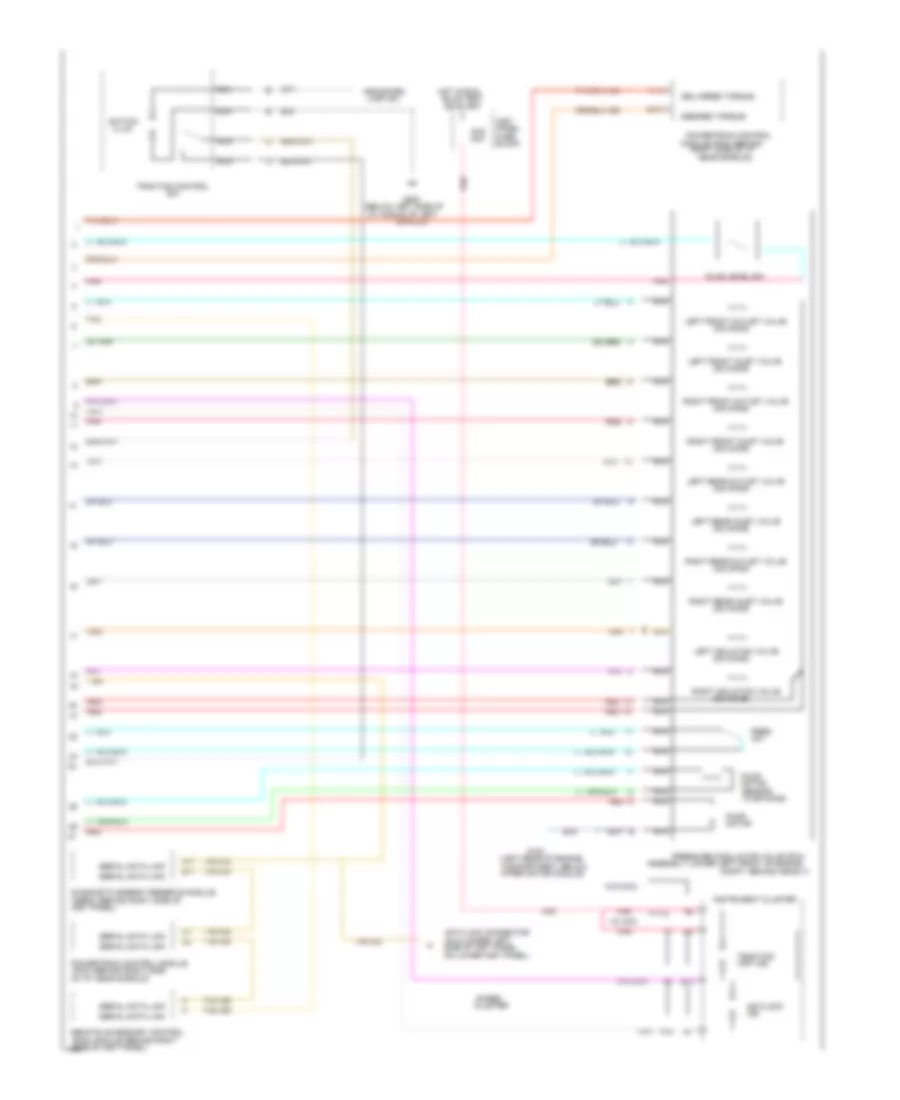
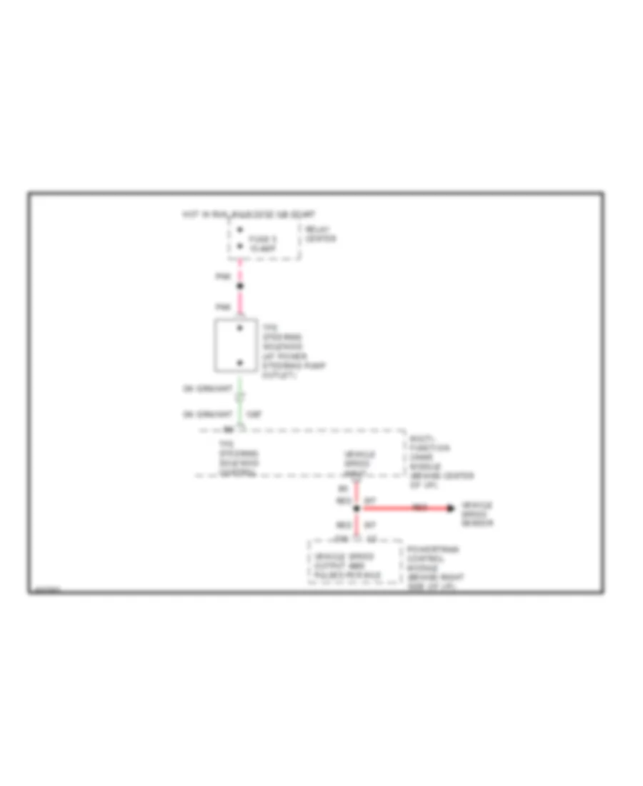
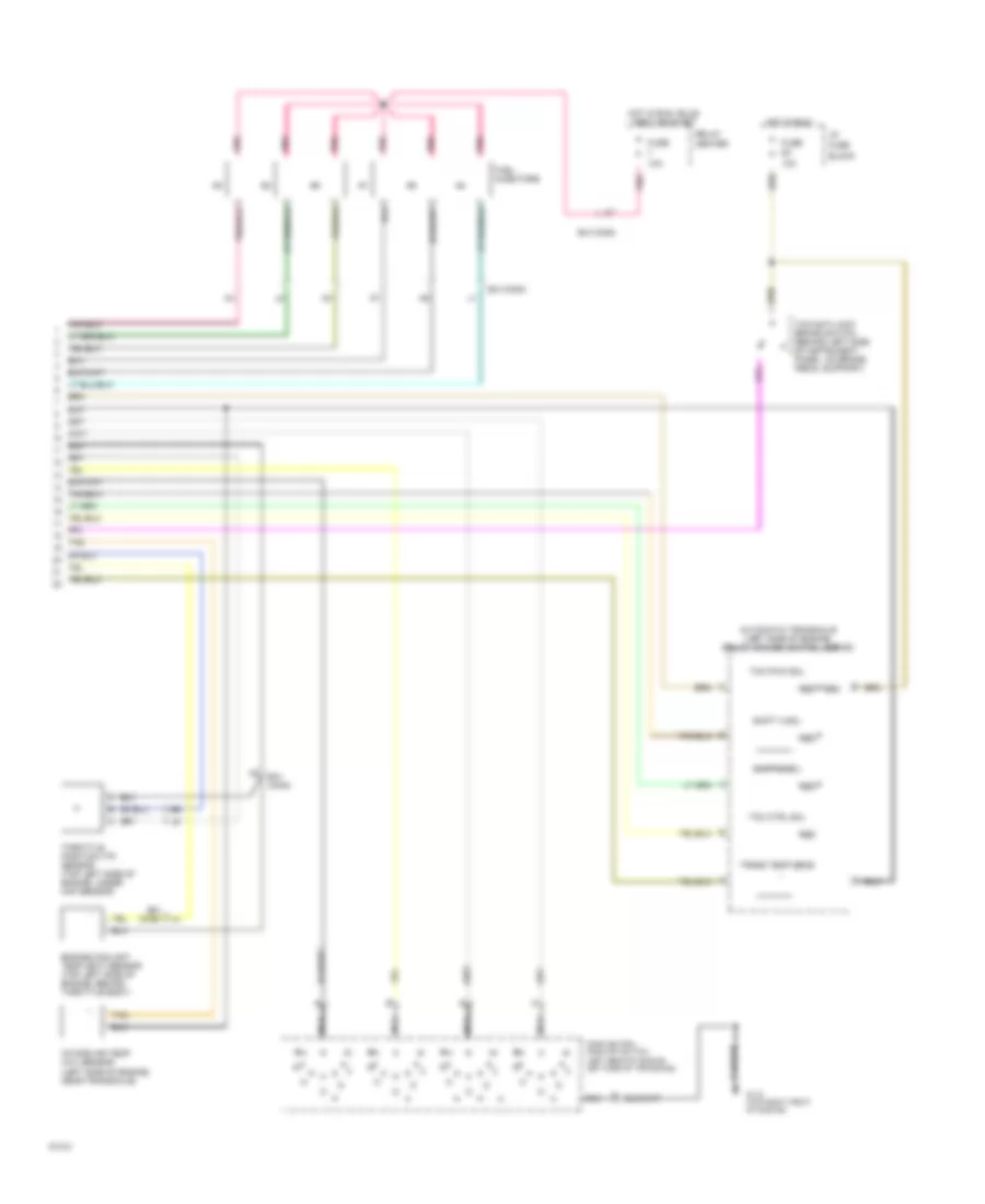
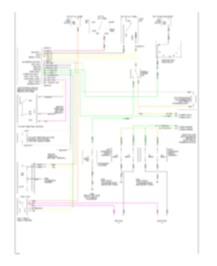
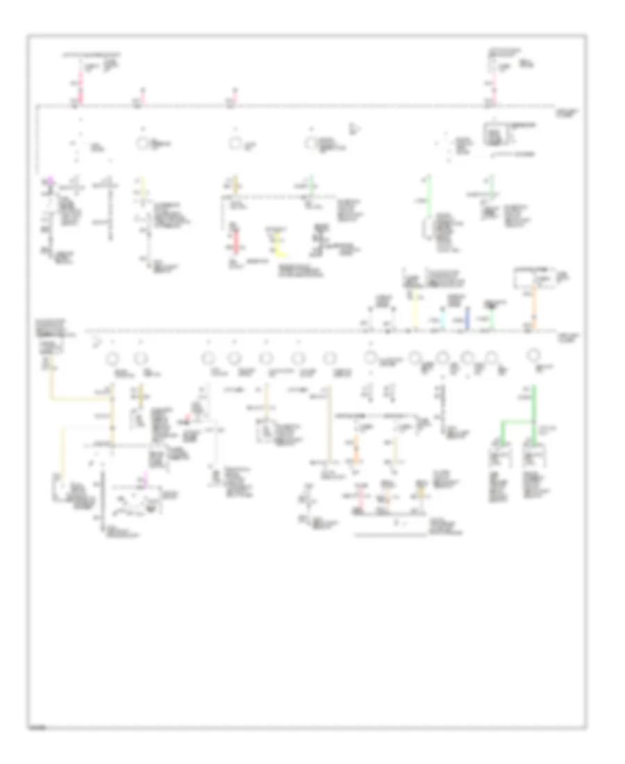
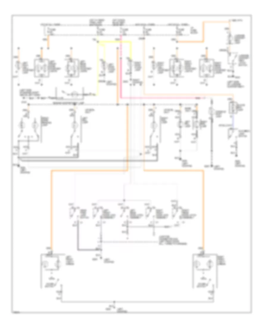
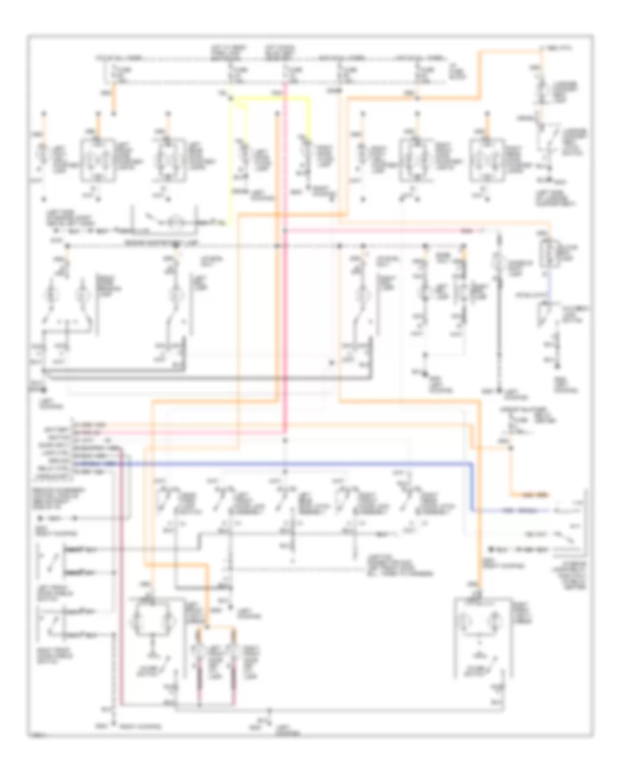
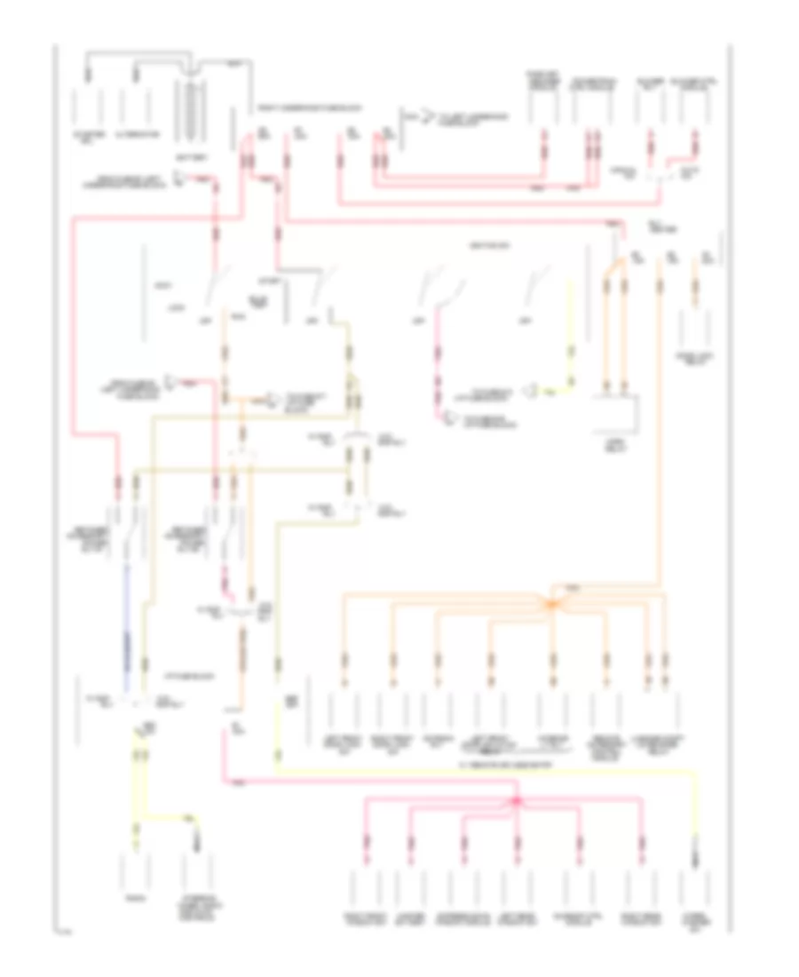
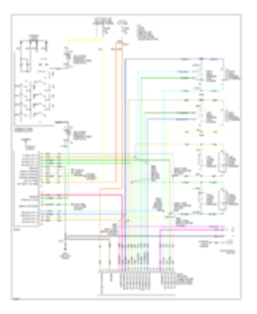
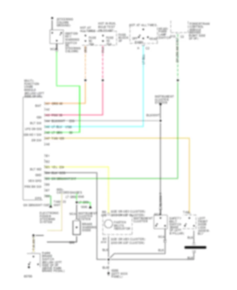
ANTI-LOCK BRAKES
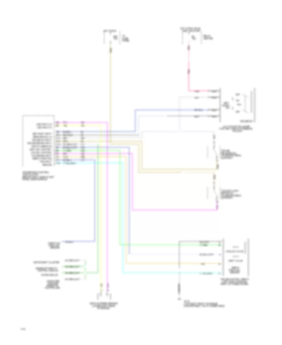
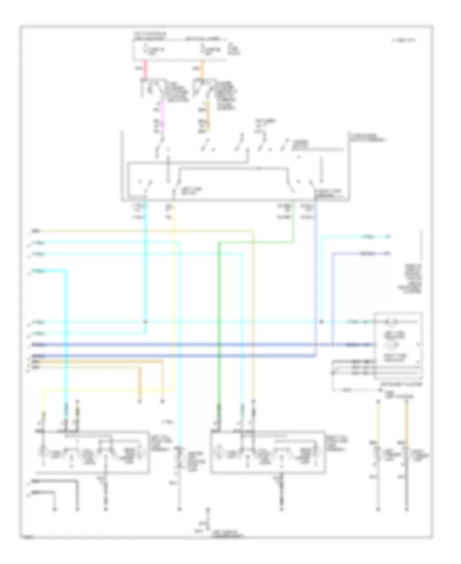
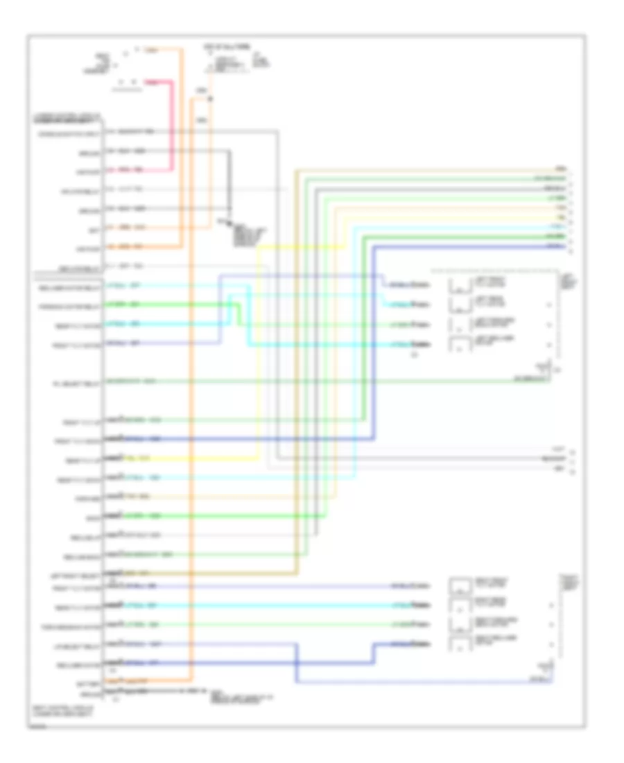
Anti-lock Brake Wiring Diagrams (1 of 2) for Pontiac Bonneville SE 1994
 https://portal-diagnostov.com/license.html
Automotive Electricians Portal FZCO
Automotive Electricians Portal FZCO
https://portal-diagnostov.com/license.html
https://portal-diagnostov.com/license.html
Automotive Electricians Portal FZCO
Automotive Electricians Portal FZCO
List of elements for Anti-lock Brake Wiring Diagrams (1 of 2) for Pontiac Bonneville SE 1994:
- #5b
- #6b
- (behind center of
- (center rear of engine
- (left front of
- (left side of engine compartment
- (right side of
- (top of brake pedal support)
- (w/ traction control)
- 10a
- 20a
- 30a
- 40a
- 87a
- Above left horn)
- Abs ind control
- Abs pump relay
- All times
- Antilock diode
- Attached to left strut tower)
- Battery power
- Block
- Brake sw (top of brake
- Composite harness)
- Compt, below left
- Control
- Control module (ebcm/ebtcm)
- Cruise/shift interlock
- Data line
- Electronic brake (& traction)
- Enable input
- Engine compartment,
- Engine, under electronic
- Fluid level input
- Fuse
- G100
- G119
- Ground
- Hot
- Hot at
- Ignition module)
- Ignition power
- In run
- Inst
- Inst panel, taped to
- Left
- Left front
- Left front inlet
- Left front outlet
- Left front sensor
- Left isolation valve
- Left rear
- Left rear inlet
- Left rear outlet
- Left rear sensor
- Main relay
- Main relay control
- Panel
- Pedal support)
- Pnk
- Pnk 1632
- Pnk 849
- Pnk 854
- Pnk 857
- Pres input
- Pump motor control
- Pump motor hi
- Pump motor lo
- Pump on request
- Red
- Red 1633
- Red 342
- Red 885
- Return input
- Right front
- Right front inlet
- Right front outlet
- Right front sensor
- Right isolation valve
- Right rear
- Right rear inlet
- Right rear outlet
- Right rear sensor
- Sense
- Sensor
- Tan
- Tan 800
- Tan 833
- Tan 848
- Tcc/antilock brake sw
- To ind control
- Traction ctrl input
- Transaxle temp input
- Underhood
- Underhood fuse block)
- Wheel speed
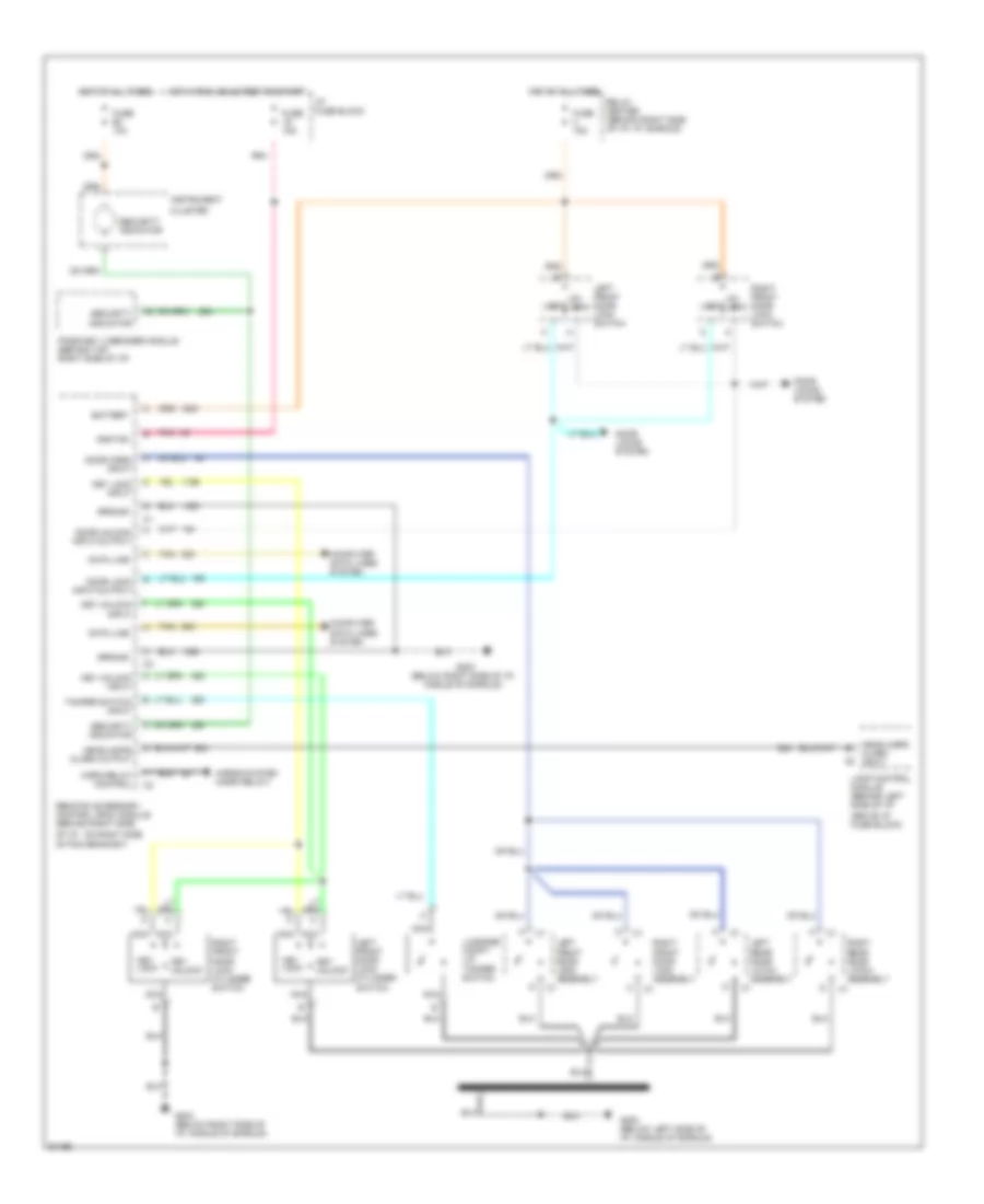
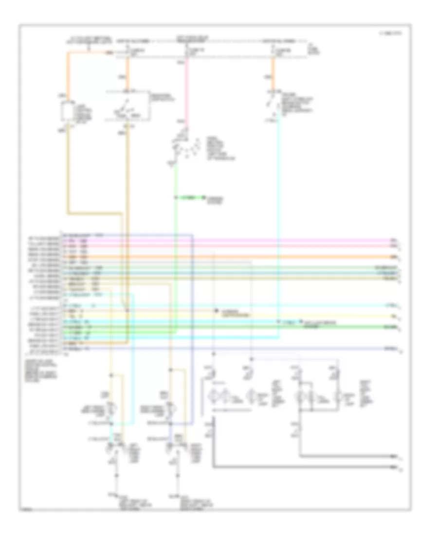
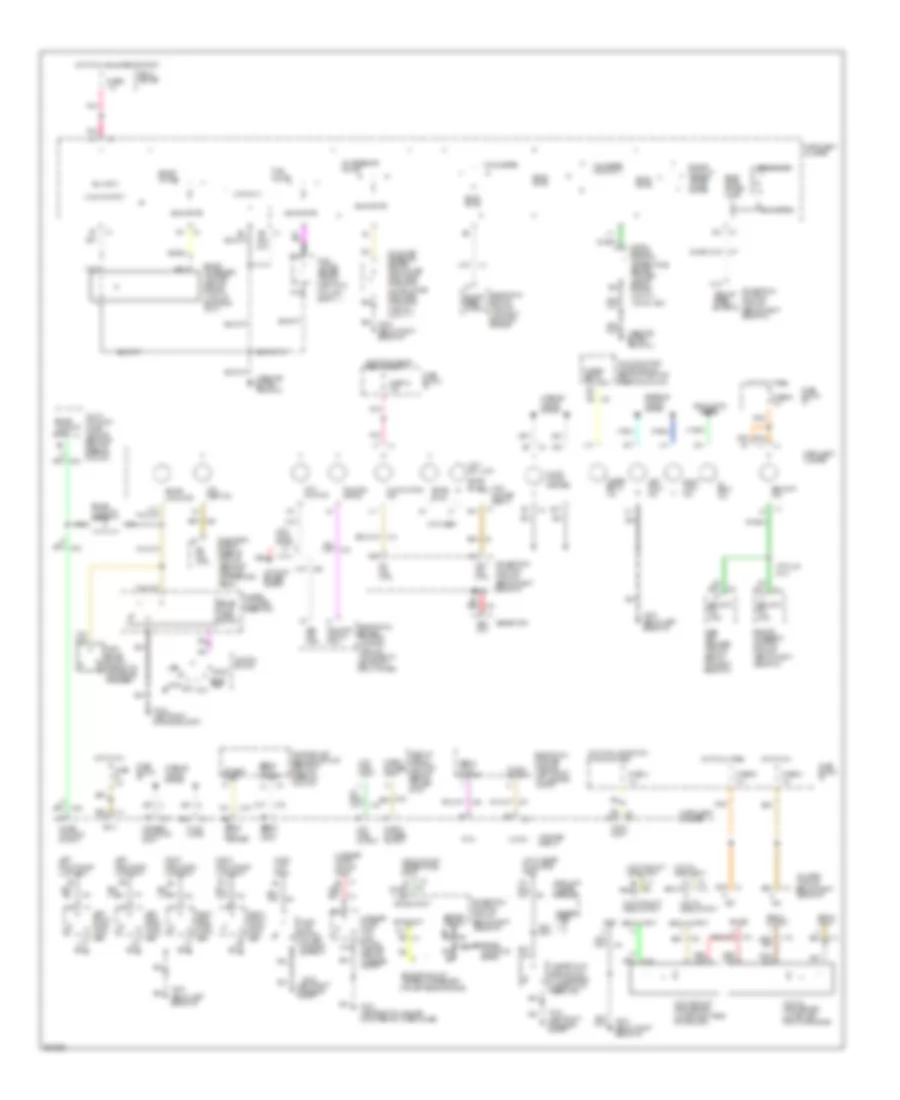
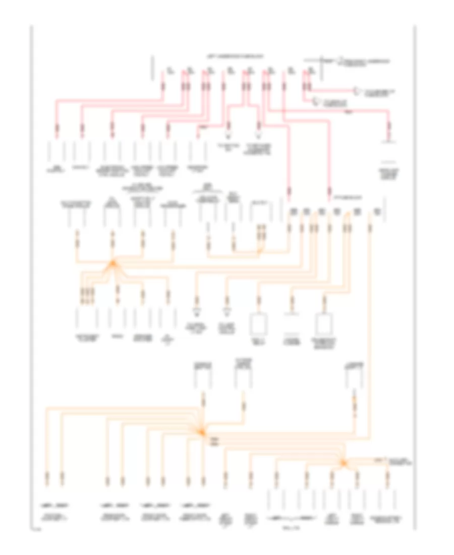
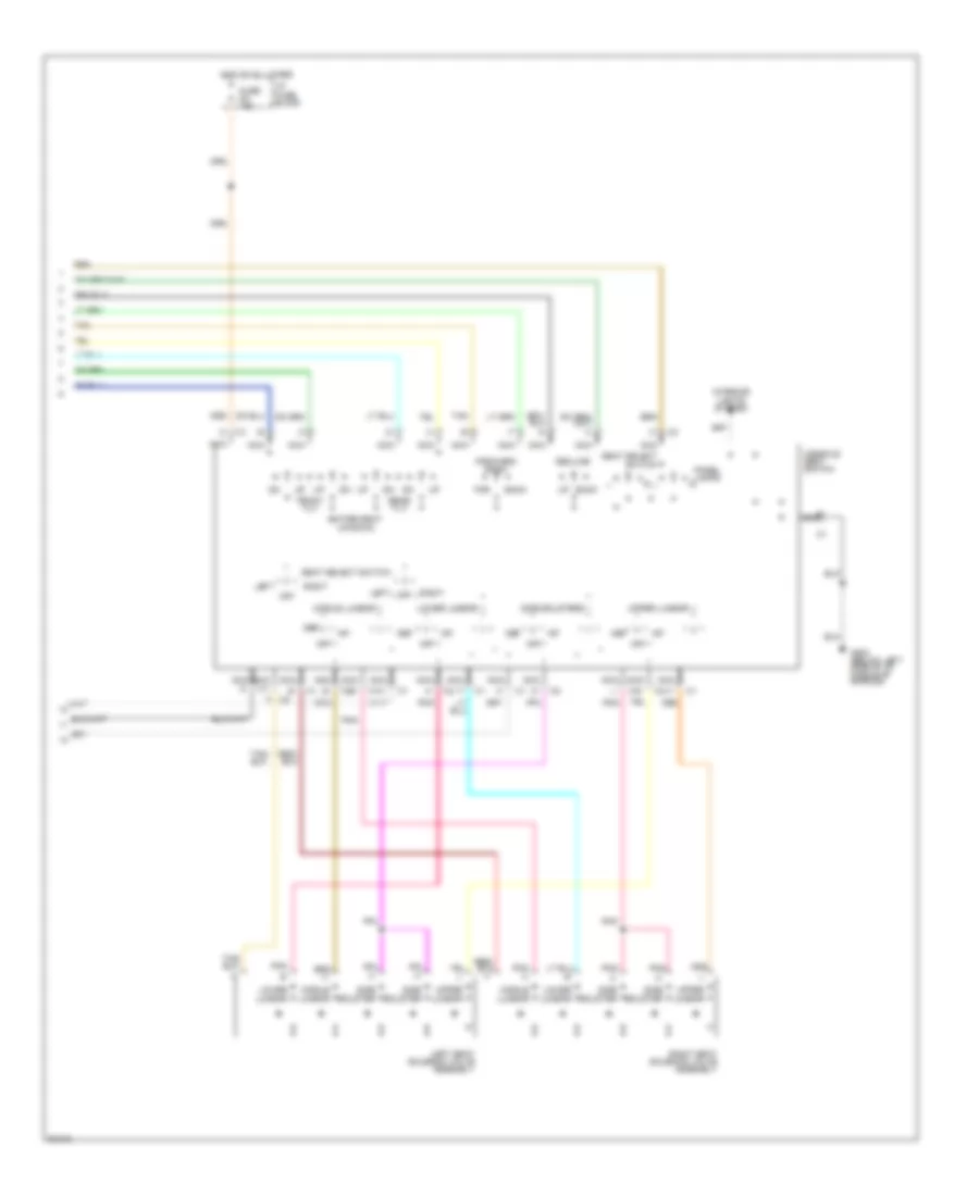
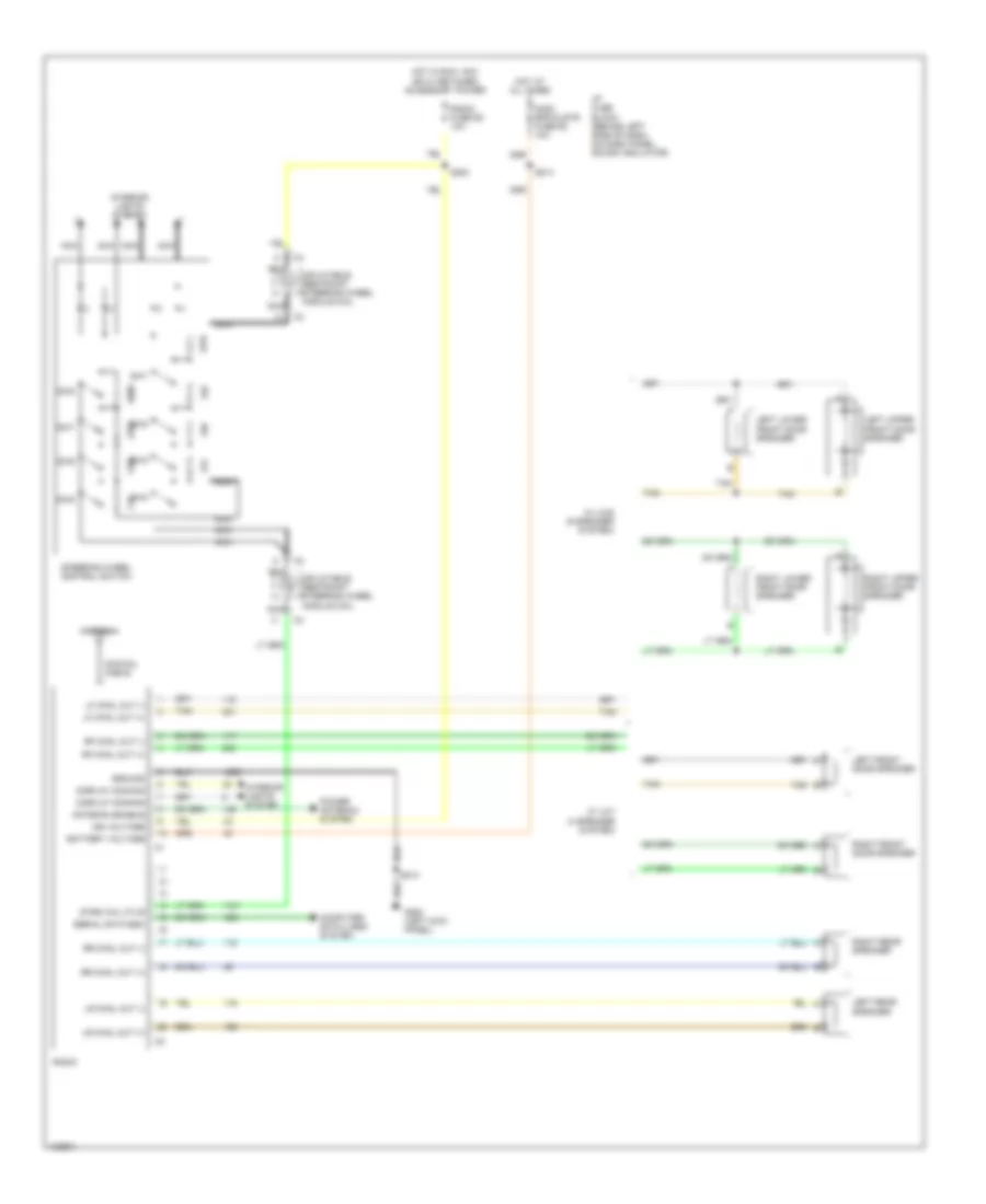
Anti-lock Brake Wiring Diagrams (2 of 2) for Pontiac Bonneville SE 1994
List of elements for Anti-lock Brake Wiring Diagrams (2 of 2) for Pontiac Bonneville SE 1994:
- "off" ind
- #1d
- (10/36 ohms)
- (3/6 ohms)
- (5/8 ohms)
- (below left side of
- (derm) (behind right side of
- (dlc) (under left
- (left rear of engine
- (pcm) (behind right side
- (rac) module (behind right
- (w/ dic)
- (w/o dic)
- 1a14
- 20a
- 2c13
- A11
- A15
- Antilock
- Assembly (lower left front of engine
- B11
- B13
- Block
- Bulb test
- Cluster
- Compartment, below
- Compt, behind headlt)
- Data link connector
- Delivered torque
- Desired torque
- Diagnostic energy reserve module
- Fluid level sw
- Fuse
- G100
- G200
- Gages
- Head/park
- Hot in run,
- I/p, middle of left
- Illum
- Ind
- Inst
- Inst panel)
- Instrument cluster
- Lamp sw
- Left front inlet valve
- Left front outlet valve
- Left isolation valve
- Left rear inlet valve
- Left rear outlet valve
- Module (pcm) (behind
- Motor
- Nca
- Near shroud)
- Of i/p, near shroud)
- On lower inst panel)
- Or start
- Panel
- Pnk
- Powertrain control
- Powertrain control module
- Pres
- Pressure modulator valve (pmv)
- Pump
- Red
- Remote accessory control
- Right front inlet valve
- Right front outlet valve
- Right isolation valve
- Right rear inlet valve
- Right rear outlet valve
- Right side of i/p
- Sensor
- Serial data link
- Shroud)
- Side of inst panel)
- Side of inst panel,
- Switch
- Tan
- Tan 800
- Traction
- Traction control
- Wiper motor module)
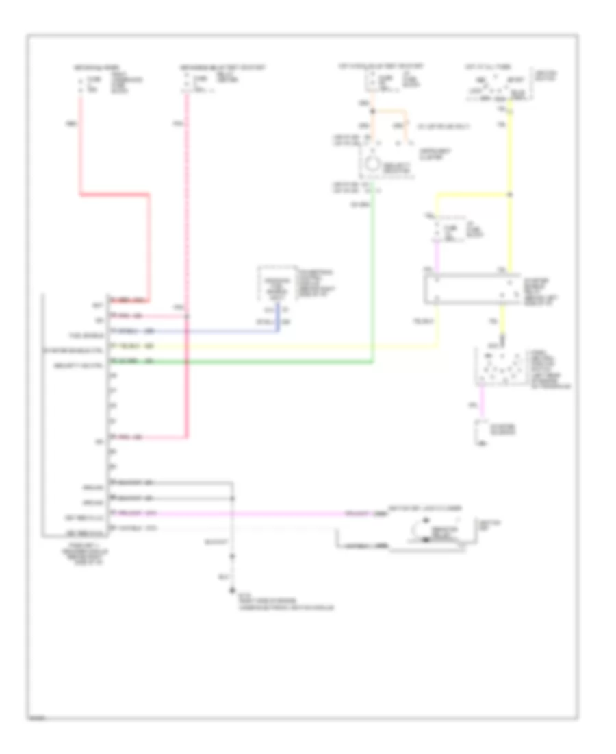
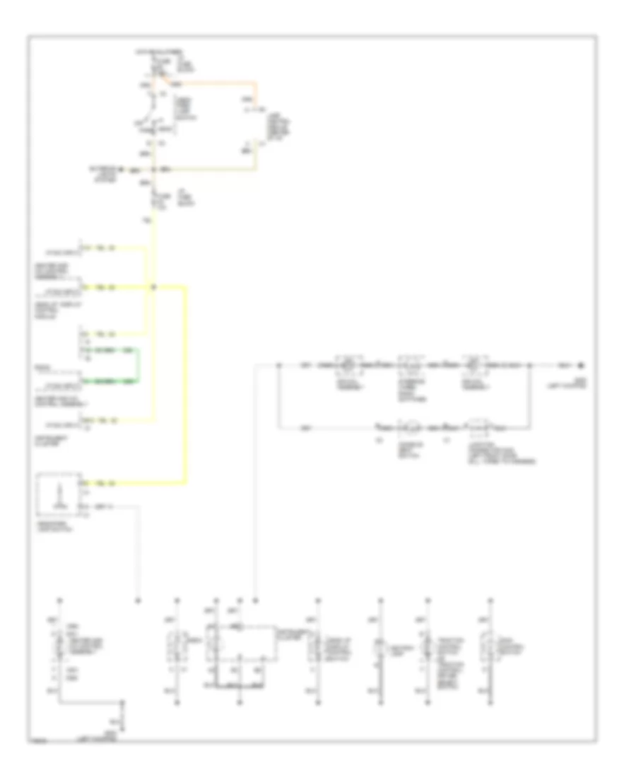
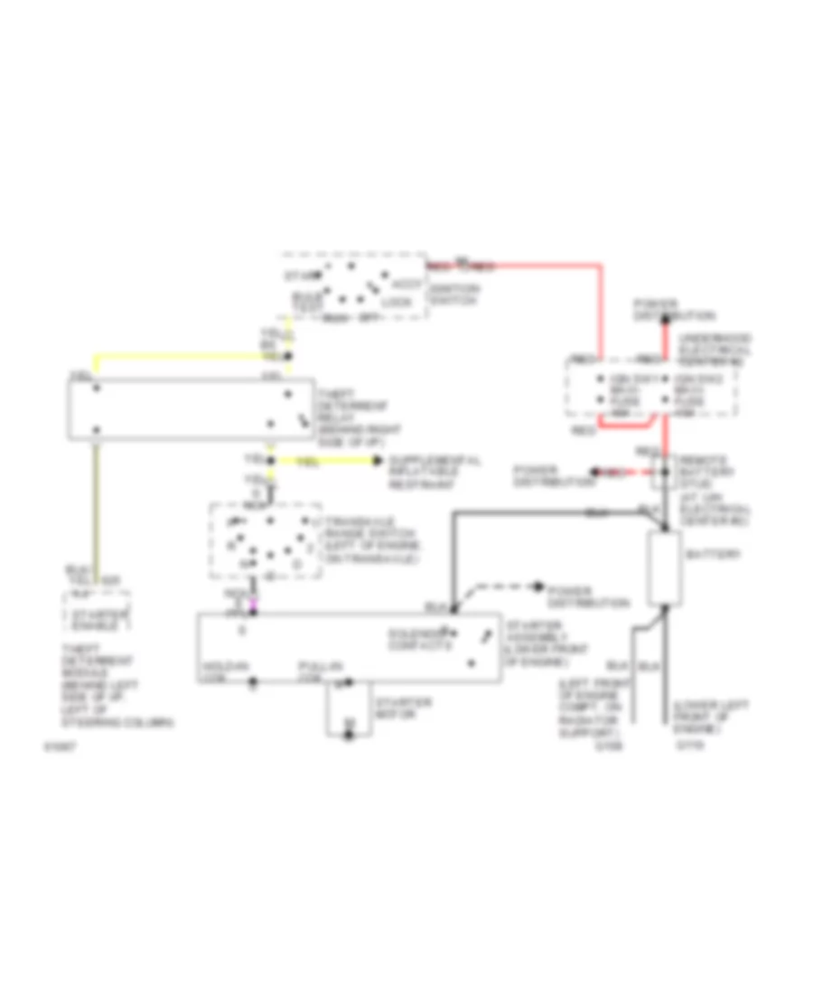
ANTI-THEFT
Anti-theft Wiring Diagram for Pontiac Bonneville SE 1994
List of elements for Anti-theft Wiring Diagram for Pontiac Bonneville SE 1994:
- A
- Above i/p fuse block)
- Battery
- C
- Cluster
- Computer data lines system
- D
- Data line
- Door lock input/output
- Door locks system
- Door open input
- Door unlock input/output
- Fuse 15a
- Fuse 1d 15a
- Fuse 9c 10a
- G200 (below left side of i/p, middle of shroud)
- G203 (below right side of i/p, middle of shroud)
- Ground
- Headlamps alarm input
- Headlamps alarm output
- Horn relay control
- Horns system (horn relay)
- Hot at all times
- Hot in run, bulb test or start
- I/p fuse block
- Ignition
- Instrument
- Key lock
- Key lock input
- Key unlock
- Key unlock input
- Lamp control module (behind left side of i/p,
- Left front door lock assembly
- Left front door lock cylinder switch
- Left front door lock switch
- Left rear door latch assembly
- Lock
- Luggage compt lid tamper switch
- Nca
- Of i/p, on right side of pcm brakcet)
- Pass-key ii decoder module (behind top right side of i/p)
- Pnk
- Relay center (behind right side of i/p, at shroud)
- Remote accessary control (rac) module (behind right side
- Right front door lock assembly
- Right front door lock cylinder switch
- Right front door lock switch
- Right rear door latch assembly
- Security indicator
- Tamper switch input
- Tan
- Un- lock
Pass-Key Wiring Diagram for Pontiac Bonneville SE 1994
List of elements for Pass-Key Wiring Diagram for Pontiac Bonneville SE 1994:
- "security" indicator
- (behind left side of i/p)
- (behind right side of i/p)
- (u2e or ub3) (u2f or u50)
- (w/ u2f or u50 only)
- Acc
- B10 a2
- B9 a1
- Bat
- Bulb test
- Cranking fuel enable input
- D14
- Decoder module
- Fuel enable
- Fuse 10a
- Fuse 1a 10a
- Fuse 20a
- Fuse 9c 10a
- G119 (right side of engine,
- Ground
- Hot at all times
- Hot in run, bulb test or start
- I/p fuse block
- Ign
- Ignition key
- Ignition key lock cylinder nca
- Ignition switch
- Instrument cluster
- Key res in (hi)
- Key res in (lo)
- Lock
- Nca
- Off
- Park/ neutral position switch (left rear of engine on transaxle)
- Pass key ii
- Pnk
- Powertrain control module (behind right side of i/p)
- Red
- Relay center
- Resistor pellet
- Right underhood fuse block
- Run
- Security ind ctrl
- Start
- Starter enable ctrl
- Starter enable relay
- Starter solenoid
- Under electronic ignition module)
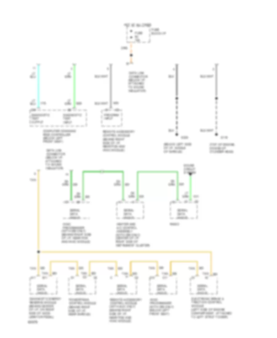
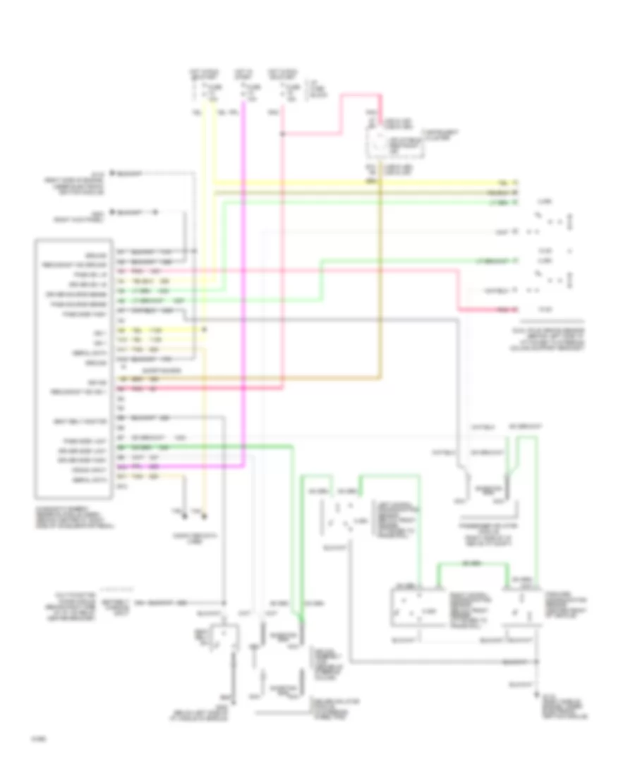
COMPUTER DATA LINES
Data Link Connector Wiring Diagram for Pontiac Bonneville SE 1994
List of elements for Data Link Connector Wiring Diagram for Pontiac Bonneville SE 1994:
- (below left side of i/p, middle of shroud)
- (top of engine, on end of cylinder head)
- A11
- C10
- C15
- Computer command ride controller (below left front seat)
- Data link connector (below i/p, attached to sound insulator)
- Diagnostic energy reserve module (behind center of i/p, on right side of acce- lerator pedal)
- Diagnostic test input
- Diagnostic test output
- Electronic brake & traction control module (left side of engine compartment, attached to left strut tower)
- Fuse 9c 10a
- Fuse block:i/p
- G119
- G200
- Heater and a/c control assembly (with c68 only) (center of i/p, right side of instrument cluster)
- Hot at all times
- Hvac programmer (with c68 only) (behind right side of i/p, near pcm and hvac module)
- Hvac programmer (with c68 only) (below left front seat)
- Powertrain control module (behind right side of i/p, near shroud)
- Program input
- Radio
- Remote accessory control module (behind right side of i/p, near pcm and hvac module)
- Remote accessory control module (with auo only) (behind right side of i/p, near pcm and hvac module)
- Serial data in/out
- Sound circuit system
- Tan
- Tan b11
- Tan c11
- Tan d2
- Tan h
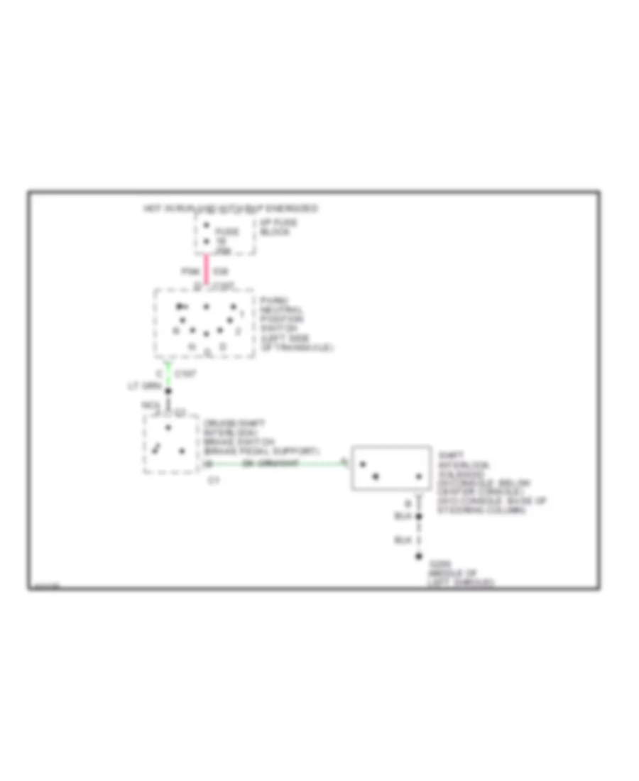
CRUISE CONTROL
Cruise Control Wiring Diagram for Pontiac Bonneville SE 1994
List of elements for Cruise Control Wiring Diagram for Pontiac Bonneville SE 1994:
- #5c
- (behind right side of inst
- (left side of engine,
- (lower right rear
- (on brake pedal
- (top left side of steering
- (top right front of engine
- 10a
- 15a
- 4000 pulses/mile
- Brake sw
- C11
- C12
- C14
- Center
- Chime module
- Coast
- Column)
- Command
- Compartment, on cylinder head)
- Computer
- Control module
- Controller
- Cruise
- Cruise brake input
- Cruise control servo
- Cruise on input
- Cruise sw
- D15
- F11
- F16
- Fuse
- G119
- Ground
- Heads/up display
- Hot in run
- Hot in run, bulb
- I/p
- Instrument cluster
- Module (pcm)
- Multi/function lever
- Nca
- Of engine)
- Off
- Panel
- Panel near shroud)
- Pnk
- Position
- Powertrain control
- R/a
- Relay
- Release sw
- Resume/accl in
- Ride(ccr)
- Right of wheelhouse)
- Sensor
- Servo
- Servo position
- Set/
- Set/cost input
- Support)
- Tan
- Tcc brake input
- Tcc/anti/lock
- Test or start
- Throttle
- Tps input
- Vac sol control
- Vacuum valve
- Vehicle speed sensor
- Vent sol control
- Vent valve
- Vss input/hi
- Vss input/lo
DEFOGGERS
Defogger Wiring Diagram for Pontiac Bonneville SE 1994
List of elements for Defogger Wiring Diagram for Pontiac Bonneville SE 1994:
- E nca
- Fuse 3d 10a
- Fuse 5a 10a
- Fuse 9e 30a
- Fuse block: i/p
- G200 (at left kick panel)
- G203 (at right shroud)
- Hot at all times
- Hot in run
- Hvac programmer
- Left mirror defogger (part of left outside mirror assembly)
- Nca
- Nca b
- Rear defogger relay (in relay center at right kick panel)
- Rear window defogger
- Relay control
- Right mirror defogger (part of right outside mirror assembly)
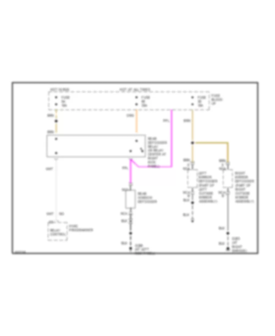
ELECTRONIC POWER STEERING
Electronic Power Steering Wiring Diagram for Pontiac Bonneville SE 1994
List of elements for Electronic Power Steering Wiring Diagram for Pontiac Bonneville SE 1994:
- D15
- Fuse 5 15 amp
- Hot in run, bulb test or start
- Multi- function chime module (behind center of i/p)
- Pnk
- Powertrain control module (behind right side of i/p)
- Red
- Relay center
- Tfe steering solenoid (at power steering pump outlet)
- Tfe steering solenoid control
- Vehicle speed input
- Vehicle speed output 4000 pulses per mile
- Vehicle speed sensor
ELECTRONIC SUSPENSION
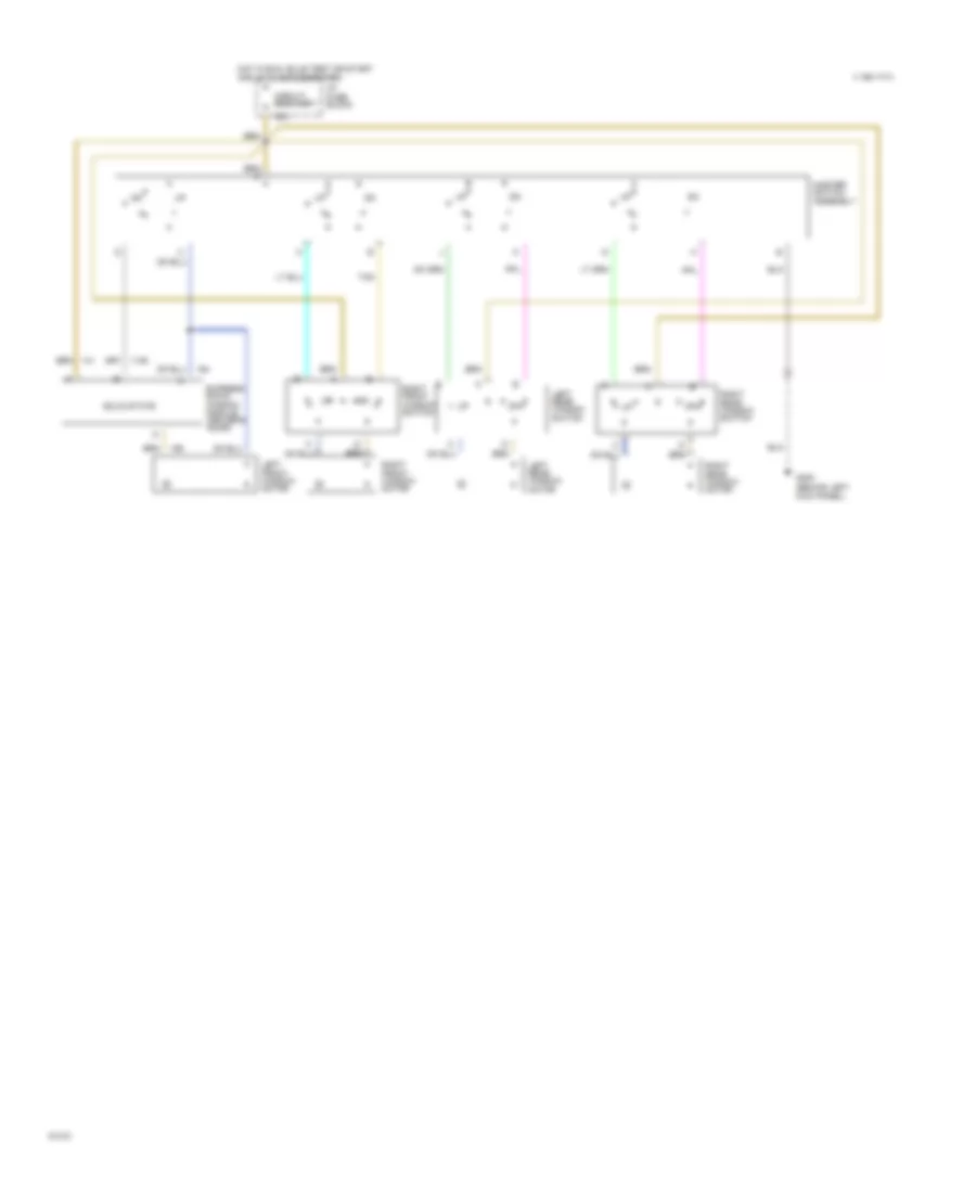
Computer Command Ride for Pontiac Bonneville SE 1994
List of elements for Computer Command Ride for Pontiac Bonneville SE 1994:
-
-
- (below left front seat)
- (console, next to shift lever)
- 10a
- C10
- C11
- C12
- C13
- C14
- C15
- C16
- Ccr switch
- Computer command ride (ccr) controller (below left front seat)
- D10
- D11
- D12
- D13
- D14
- D15
- D16
- Data link connector (below left i/p, next to i/p fuse block)
- Diagnostic test in
- Diagnostic test out
- Firm input
- Fuse 5b
- G# n/a
- G119 (right front of engine, under electronic ignition module)
- G200 (below left side of i/p, middle of shroud)
- Ground
- Hot in run
- I/p fuse block
- Ign input
- Lateral accel sw in
- Lateral acceleration switch
- Left front strut
- Left rear strut
- Lf motor drive
- Lf position in
- Lr motor drive
- Lr position in
- Nca
- Normal input
- Perf
- Pnk
- Pos out 2
- Pos out 3
- Powertrain control module (behind right i/p, behind relay center, against bulkhead)
- Red
- Rf motor drive
- Rf position in
- Right front strut
- Right rear strut
- Rr motor drive
- Rr position in
- Tour
- Vehicle speed input
- Vehicle speed output
- Wot input
- Wot output
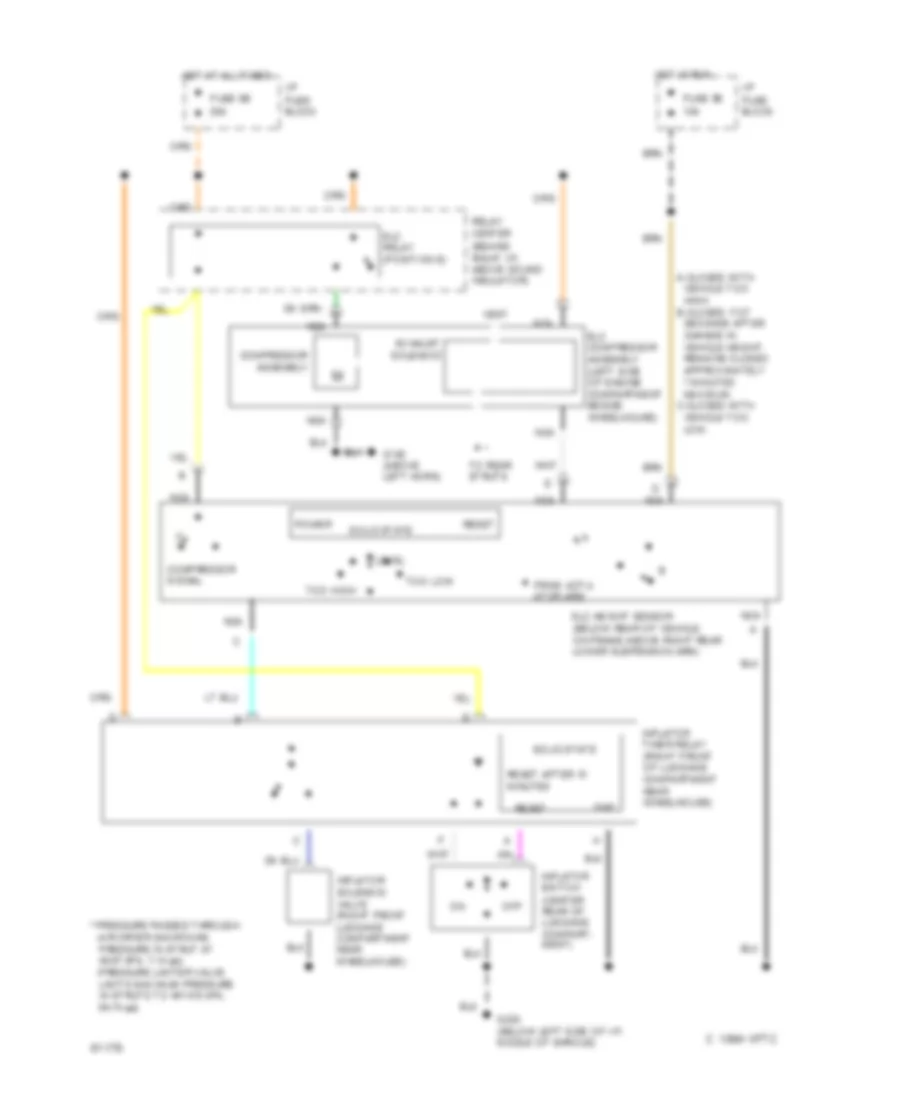
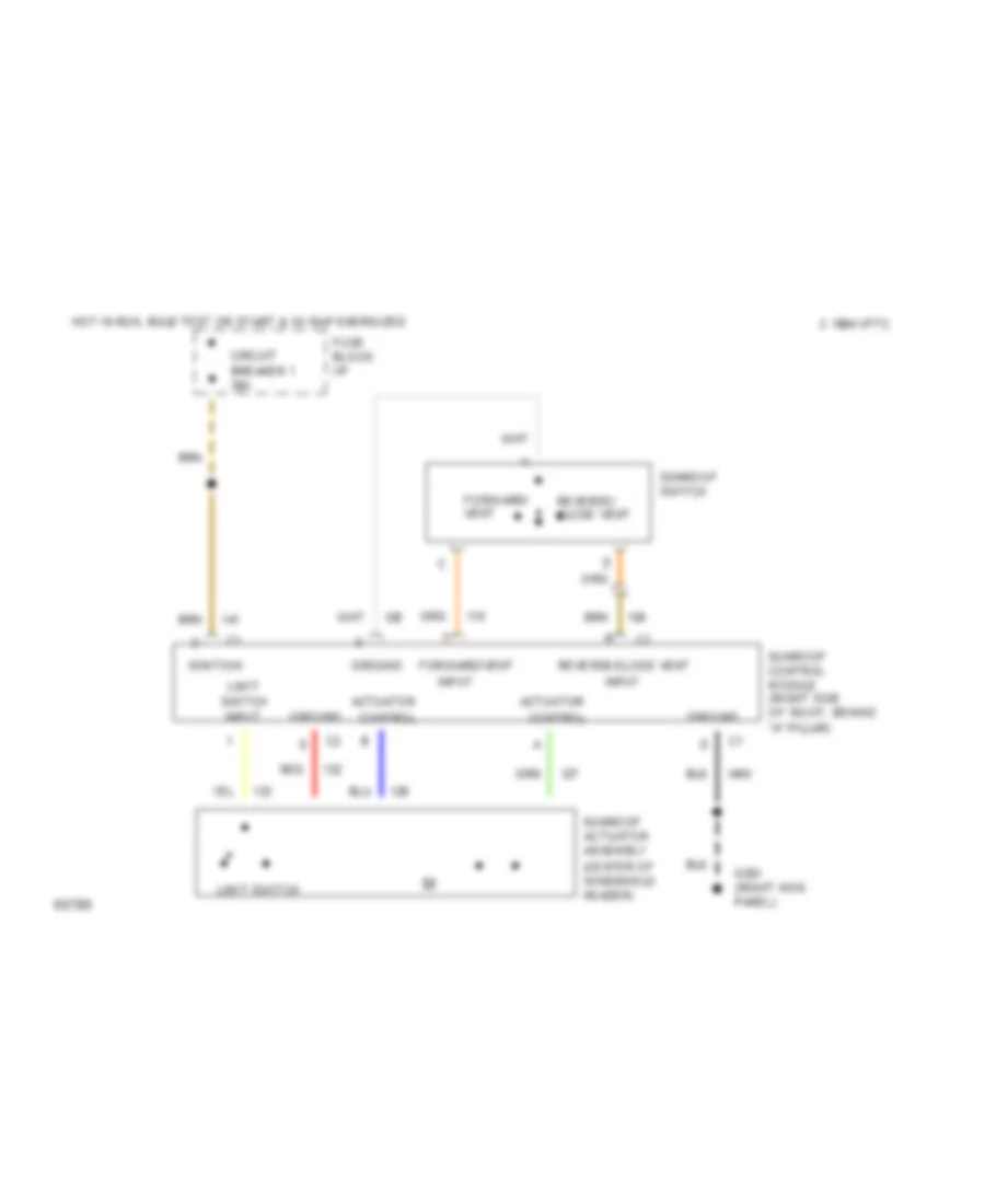
Electronic Level Control (with Assembly Inflator) for Pontiac Bonneville SE 1994
List of elements for Electronic Level Control (with Assembly Inflator) for Pontiac Bonneville SE 1994:
- * pressure passes through: -air dryer (maintains pressure in strut at 48-97 kpa, 7-14 psi) -pressure limiter valve limits maximum pressure in struts to 447-510 kpa, 64-74 psi)
- 1994 vftc c
- A-closes with vehicle too high. b-closes 17-27 seconds after change in vehicle height. remains closed approximately 7 minutes maximum. c-closes with vehicle too low.
- Compressor assembly
- Compressor signal
- Elc compressor assembly (left side of engine compartment beside wheelhouse)
- Elc height sensor (below rear of vehicle, on frame above right rear lower suspension arm)
- Elc relay (position e)
- Exhaust solenoid
- From actu- ator arm
- Fuse 5b 10a
- Fuse 9b 20a
- G100 (above left horn)
- G200 (below left side of i/p, middle of shroud)
- Gnd
- Hot at all times
- Hot in run
- I/p fuse block
- Inflator solenoid valve (right front luggage compartment near wheelhouse)
- Inflator switch (center rear of luggage compart- ment)
- Inflator timer relay (right front of luggage compartment near wheelhouse)
- Level
- Nca
- Off
- Power
- Relay center (behind right i/p, above sound insulator)
- Reset
- Reset
- Reset after 10 minutes
- Solid state
- To rear struts
- Too high
- Too low
- Vent
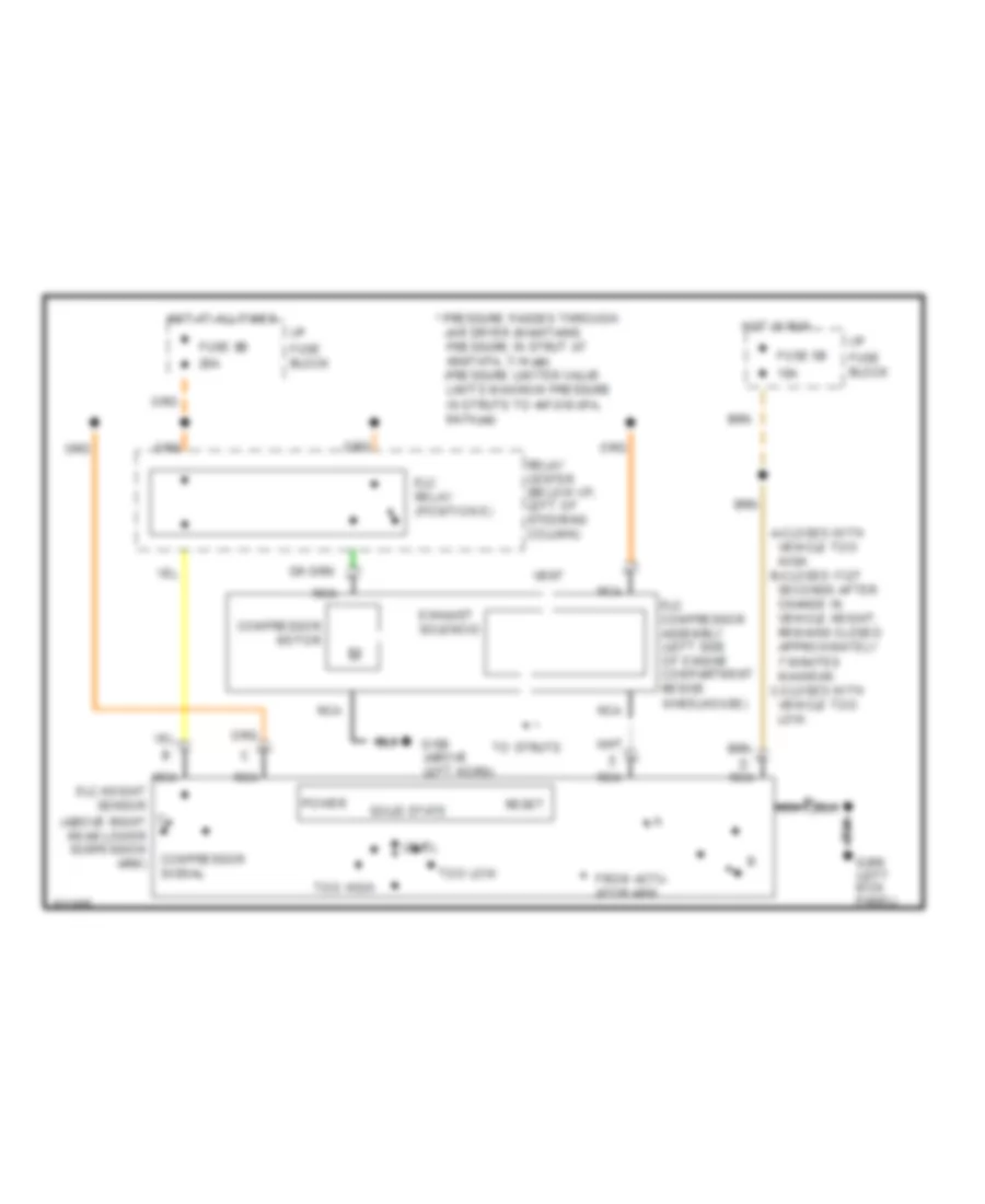
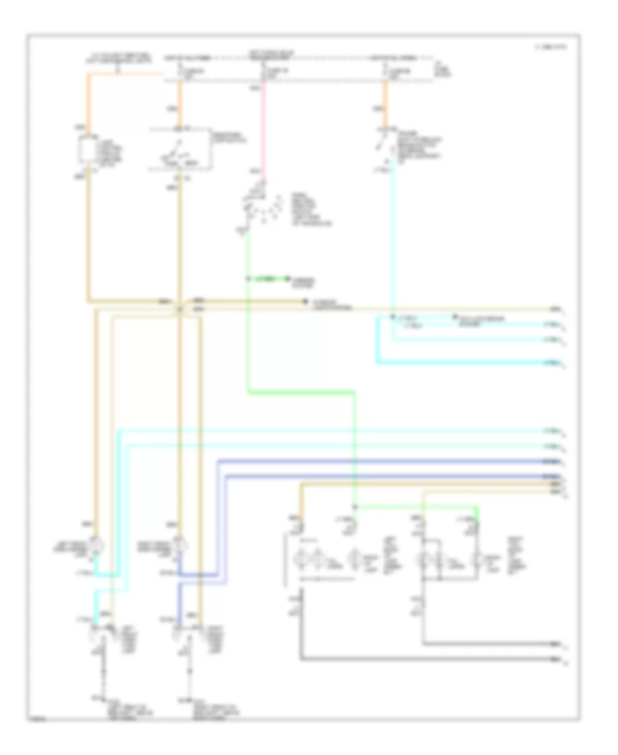
Electronic Level Control (without Assembly Inflator) for Pontiac Bonneville SE 1994
List of elements for Electronic Level Control (without Assembly Inflator) for Pontiac Bonneville SE 1994:
- to struts
- * pressure passes through: -air dryer (maintains pressure in strut at 48-97 kpa, 7-14 psi) -pressure limiter valve limits maximum pressure in struts to 447-510 kpa, 64-74 psi)
- A-closes with vehicle too high. b-closes 17-27 seconds after change in vehicle height. remains closed approximately 7 minutes maximum. c-closes with vehicle too low.
- Compressor motor
- Compressor signal
- Elc compressor assembly (left side of engine compartment beside wheelhouse)
- Elc relay (position e)
- Exhaust solenoid
- From actu- ator arm
- Fuse 5b 10a
- Fuse 9b 20a
- G100 (above left horn)
- G200 (left kick panel)
- Hot at all times
- Hot in run
- I/p fuse block
- Level
- Nca
- Nca elc height sensor (above right rear lower suspension arm)
- Power
- Relay center (below i/p, left of steering column)
- Reset
- Solid state
- Too high
- Too low
- Vent
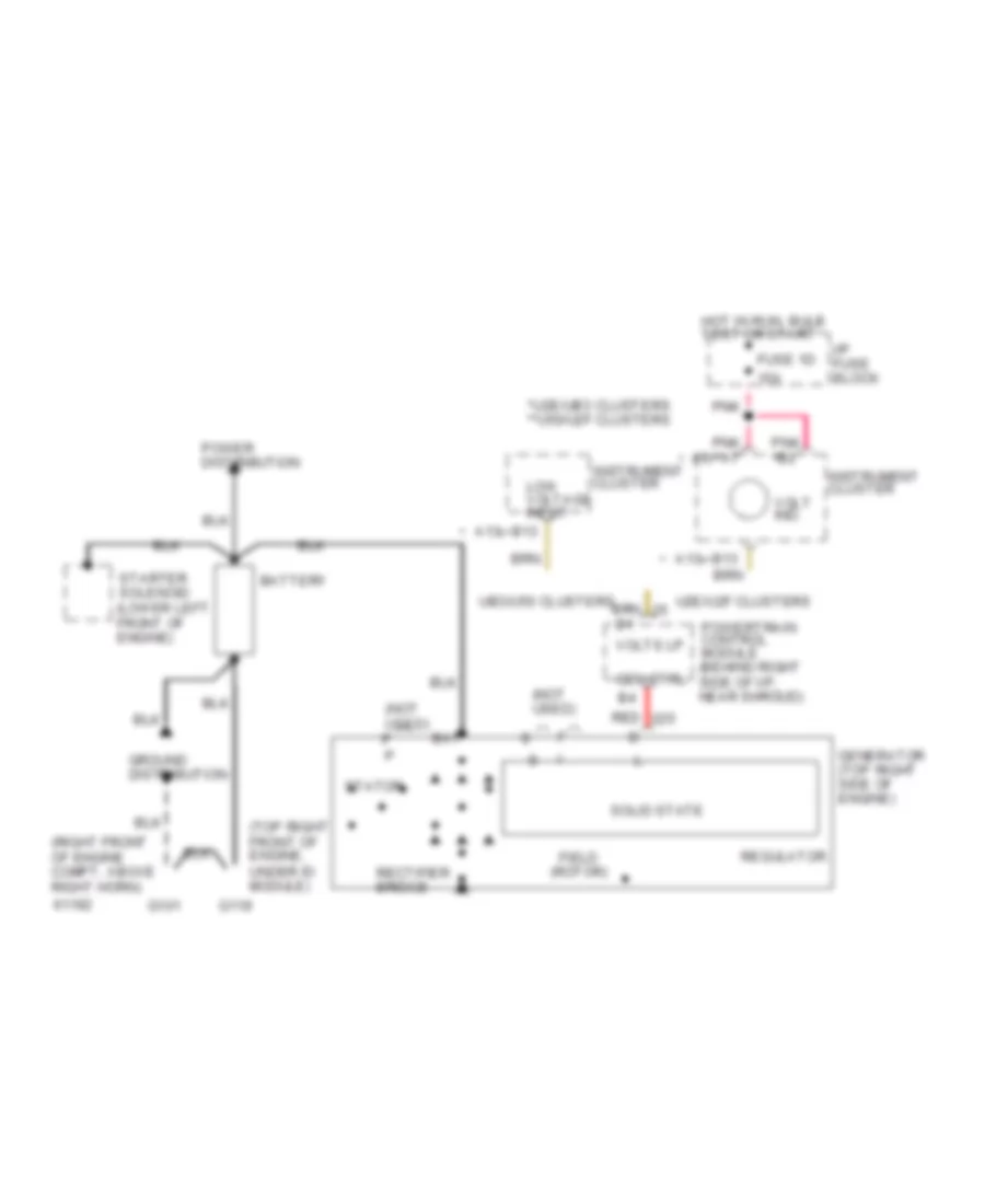
ENGINE PERFORMANCE
3.8L
3.8L (VIN 1), Engine Performance Wiring Diagrams (1 of 3) for Pontiac Bonneville SE 1994
List of elements for 3.8L (VIN 1), Engine Performance Wiring Diagrams (1 of 3) for Pontiac Bonneville SE 1994:
-
-
-
-
- (behind right side of instrument
- 20a
- 4k/mi speedo
- 5 volt ref
- 87a
- A/c head press. switch
- A/c relay ctrl
- A/c request in
- A10
- A11
- A12
- A13
- A14
- A15
- A16
- Air conditioning
- B/h
- B/h conn
- B/h conn k2
- B10
- B11
- B12
- B13
- B14
- B15
- B16
- Battery
- Buick only
- Bypass ctrl
- C10
- C11
- C12
- C13
- C14
- C15
- C16
- Cam signal ref in
- Ccr brake/throttle out
- Center
- Change oil lamp
- Computer command ride controller
- Computer command ride controller (below left front seat)
- Computer data lines
- Conn
- Conn c1
- Conn c2
- Cool fan rly ctrl-hi spd
- Cool fan rly ctrl-lo spd
- Coolant fan relays
- Coolant temp ind ctrl
- Cruise brake in
- Cruise control
- Cruise on in
- D10
- D11
- D12
- D13
- D15
- D16
- Data line in/out
- Data link connector
- Delivered torque
- Desired torque
- Egr solenoid ctrl
- Electronic brake and traction control module
- Est ctrl out
- Front of air intake assembly)
- Fuel ctrl ref in
- Fuel injector #1 ctrl
- Fuel injector #2 ctrl
- Fuel injector #3 ctrl
- Fuel injector #4 ctrl
- Fuel injector #5 ctrl
- Fuel injector #6 ctrl
- Fuel pump (fuel tank unit)
- Fuel pump prime connector (front right of engine compt)
- Fuel pump relay (relay center, behind right side of inst panel, top of right shroud)
- Fuel pump relay ctrl
- Fuse
- Fuse 10a
- Fuse 15a
- Fuse 1d 15a
- Fuse 20a
- Fuse block
- G119 (top right front of engine, on end of cylinder head)
- G200 (left kick panel)
- Generator
- Generator control
- Ground
- Hot at all times
- Hot in run, bulb
- Hot in run, bulb test or start
- I/p
- Idle air control motor (iac) (top left side of engine,
- Idle air ctrl
- Ign
- Ignition
- Instrument cluster
- Instrument cluster (change oil lamp)
- Instrument cluster (except park avenue) information center (park avenue)
- Instrument cluster (volts indicator)
- Maf sensor in
- Malfunction ind ctrl
- Malfunction indicator
- Mass air flow (maf) sensor (front of air intake system)
- Multi function chime module (behind center of i/p)
- Oil life monitor reset
- Oil life monitor reset switch
- Oil pres sw (ind clstr), oil pres sender/sw (gages clstr), (lower right side of engine, above oil filter)
- Panel, near shroud)
- Pass key fuel enable
- Pass- key ii decoder module (right side of i/p)
- Pnk
- Powertrain control module (pcm)
- Red
- Ref lo in
- Relay
- Resume/accel in
- Right underhood fuse block
- Sensor return
- Set/coast in
- Spark ref in
- Tan
- Tcc pwm solenoid ctrl
- Test or start
- Vehicle speed sensor (vss) (lower right rear of engine)
- Volts lamp
- Vss
3.8L (VIN 1), Engine Performance Wiring Diagrams (2 of 3) for Pontiac Bonneville SE 1994
List of elements for 3.8L (VIN 1), Engine Performance Wiring Diagrams (2 of 3) for Pontiac Bonneville SE 1994:
-
-
-
-
- (behind right side of instrument
- 5 volt ref
- A tan
- B/h conn
- Boost solenoid
- Boost solenoid (vin 1) (top left side of engine, above left end of front valve cover)
- Buffer/ amplifier
- Bypass switch
- C5 b/h conn
- Camshaft position sensor (lower side of engine, above lower pulley)
- Canister purge ctrl
- Center
- Coils
- Conn c3
- Crankshaft sensor (lower right side of engine, ahead of lower pulley)
- Cruise control
- E10
- E11
- E12
- E13
- E14
- E15
- E16
- Ect sensor in
- Egr signal in
- Electronic ignition (ei) module (top right front of engine)
- Evaporative emission canister purge solenoid (left front corner of engine compt, top of vapor canister)
- Exhaust gas recirculation electronic vacuum regulator solenoid valve (top left front of engine, left end of front valve cover)
- F10
- F11
- F12
- F13
- F14
- F15
- F16
- Fuse 15a
- Fuse 20a
- G119 (top right front of engine)
- Hall effect sensor
- Heated oxygen sensor (lower rear of engine, on exhaust manifold)
- Hot in run, bulb test or start
- Iat sensor in
- Ignition
- Knock sensor (lower right rear of engine, left of oil filter)
- Knock sensor in
- Oxygen sensor in-hi
- Oxygen sensor in-lo
- P/n pos sw parity in
- Panel, near shroud)
- Park/neut pos sw a in
- Park/neut pos sw b in
- Park/neut pos sw c in
- Pnk
- Powertrain control module (pcm)
- Relay
- Sensor feed
- Sensor ground
- Sensor return
- Servo pos sensor in
- Shift a solenoid ctrl
- Shift b solenoid ctrl
- Spark plugs
- Sws/ amplifier
- Tach
- Tachometer (instrument cluster)
- Tan
- Tcc brake in
- Tcc solenoid ctrl
- Tp sensor in
- Transmission temp in
- Vacuum solenoid ctrl
- Vent solenoid ctrl
3.8L (VIN 1), Engine Performance Wiring Diagrams (3 of 3) for Pontiac Bonneville SE 1994
List of elements for 3.8L (VIN 1), Engine Performance Wiring Diagrams (3 of 3) for Pontiac Bonneville SE 1994:
-
-
-
- 10a
- Automatic transaxle (left side of engine, below cruise control servo)
- B/h conn
- Block
- Center
- Engine coolant temp (ect) sensor (top left side of engine, behind throttle body)
- Fuel injectors
- Fuse
- G119 (top right front of engine)
- Hot in run
- Hot in run, bulb test or start
- I/p
- Intake air temp (iat) sensor (left side of engine, near transaxle)
- Nca
- Park/neutral position switch (left rear of engine, left side of transaxle)
- Pnk
- Red
- Relay
- Shift a sol
- Shift b sol
- Tan
- Tcc ctrl sol
- Tcc pwm sol
- Tcc/anti-lock brake switch (behind left side of instrument panel, on brake pedal support)
- Throttle position (tp) sensor (top left side of engine, under maf sensor)
- Trans temp sens
3.8L (VIN L), Engine Performance Wiring Diagrams (1 of 3) for Pontiac Bonneville SE 1994
List of elements for 3.8L (VIN L), Engine Performance Wiring Diagrams (1 of 3) for Pontiac Bonneville SE 1994:
-
-
-
-
- (behind right side of instrument
- 20a
- 4k/mi speedo
- 5 volt ref
- 87a
- A/c head press. switch
- A/c relay ctrl
- A/c request in
- A10
- A11
- A12
- A13
- A14
- A15
- A16
- Air conditioning
- B/h
- B/h conn
- B/h conn k2
- B10
- B11
- B12
- B13
- B14
- B15
- B16
- Battery
- Buick only
- Bypass ctrl
- C10
- C11
- C12
- C13
- C14
- C15
- C16
- Cam signal ref in
- Ccr brake/throttle out
- Center
- Change oil lamp
- Computer command ride controller
- Computer command ride controller (below left front seat)
- Computer data lines
- Conn
- Conn c1
- Conn c2
- Cool fan rly ctrl-hi spd
- Cool fan rly ctrl-lo spd
- Coolant fan relays
- Coolant temp ind ctrl
- Cruise brake in
- Cruise control
- Cruise on in
- D10
- D11
- D12
- D13
- D15
- D16
- Data line in/out
- Data link connector
- Delivered torque
- Desired torque
- Egr solenoid ctrl
- Electronic brake and traction control module
- Est ctrl out
- Front of air intake assembly)
- Fuel ctrl ref in
- Fuel injector #1 ctrl
- Fuel injector #2 ctrl
- Fuel injector #3 ctrl
- Fuel injector #4 ctrl
- Fuel injector #5 ctrl
- Fuel injector #6 ctrl
- Fuel pump (fuel tank unit)
- Fuel pump prime connector (front right of engine compt)
- Fuel pump relay (relay center, behind right side of inst panel, top of right shroud)
- Fuel pump relay ctrl
- Fuse
- Fuse 10a
- Fuse 15a
- Fuse 1d 15a
- Fuse 20a
- Fuse block
- G119 (top right front of engine, on end of cylinder head)
- G200 (left kick panel)
- Generator
- Generator control
- Ground
- Hot at all times
- Hot in run, bulb
- Hot in run, bulb test or start
- I/p
- Idle air control motor (iac) (top left side of engine,
- Idle air ctrl
- Ign
- Ignition
- Instrument cluster
- Instrument cluster (change oil lamp)
- Instrument cluster (except park avenue) information center (park avenue)
- Instrument cluster (volts indicator)
- Maf sensor in
- Malfunction ind ctrl
- Malfunction indicator
- Mass air flow (maf) sensor (front of air intake system)
- Multi function chime module (behind center of i/p)
- Oil life monitor reset
- Oil life monitor reset switch
- Oil pres sw (ind clstr), oil pres sender/sw (gages clstr), (lower right side of engine, above oil filter)
- Panel, near shroud)
- Pass key fuel enable
- Pass- key ii decoder module (right side of i/p)
- Pnk
- Powertrain control module (pcm)
- Red
- Ref lo in
- Relay
- Resume/accel in
- Right underhood fuse block
- Sensor return
- Set/coast in
- Spark ref in
- Tan
- Tcc pwm solenoid ctrl
- Test or start
- Vehicle speed sensor (vss) (lower right rear of engine)
- Volts lamp
- Vss
3.8L (VIN L), Engine Performance Wiring Diagrams (2 of 3) for Pontiac Bonneville SE 1994
List of elements for 3.8L (VIN L), Engine Performance Wiring Diagrams (2 of 3) for Pontiac Bonneville SE 1994:
-
-
-
-
- (behind right side of instrument
- 5 volt ref
- A tan
- B/h conn
- Boost solenoid
- Boost solenoid (vin 1) (top left side of engine, above left end of front valve cover)
- Buffer/ amplifier
- Bypass switch
- C5 b/h conn
- Camshaft position sensor (lower side of engine, above lower pulley)
- Canister purge ctrl
- Center
- Coils
- Conn c3
- Crankshaft sensor (lower right side of engine, ahead of lower pulley)
- Cruise control
- E10
- E11
- E12
- E13
- E14
- E15
- E16
- Ect sensor in
- Egr signal in
- Electronic ignition (ei) module (top right front of engine)
- Evaporative emission canister purge solenoid (left front corner of engine compt, top of vapor canister)
- Exhaust gas recirculation electronic vacuum regulator solenoid valve (top left front of engine, left end of front valve cover)
- F10
- F11
- F12
- F13
- F14
- F15
- F16
- Fuse 15a
- Fuse 20a
- G119 (top right front of engine)
- Hall effect sensor
- Heated oxygen sensor (lower rear of engine, on exhaust manifold)
- Hot in run, bulb test or start
- Iat sensor in
- Ignition
- Knock sensor (lower right rear of engine, left of oil filter)
- Knock sensor in
- Oxygen sensor in-hi
- Oxygen sensor in-lo
- P/n pos sw parity in
- Panel, near shroud)
- Park/neut pos sw a in
- Park/neut pos sw b in
- Park/neut pos sw c in
- Pnk
- Powertrain control module (pcm)
- Relay
- Sensor feed
- Sensor ground
- Sensor return
- Servo pos sensor in
- Shift a solenoid ctrl
- Shift b solenoid ctrl
- Spark plugs
- Sws/ amplifier
- Tach
- Tachometer (instrument cluster)
- Tan
- Tcc brake in
- Tcc solenoid ctrl
- Tp sensor in
- Transmission temp in
- Vacuum solenoid ctrl
- Vent solenoid ctrl
3.8L (VIN L), Engine Performance Wiring Diagrams (3 of 3) for Pontiac Bonneville SE 1994
List of elements for 3.8L (VIN L), Engine Performance Wiring Diagrams (3 of 3) for Pontiac Bonneville SE 1994:
-
-
-
- 10a
- Automatic transaxle (left side of engine, below cruise control servo)
- B/h conn
- Block
- Center
- Engine coolant temp (ect) sensor (top left side of engine, behind throttle body)
- Fuel injectors
- Fuse
- G119 (top right front of engine)
- Hot in run
- Hot in run, bulb test or start
- I/p
- Intake air temp (iat) sensor (left side of engine, near transaxle)
- Nca
- Park/neutral position switch (left rear of engine, left side of transaxle)
- Pnk
- Red
- Relay
- Shift a sol
- Shift b sol
- Tan
- Tcc ctrl sol
- Tcc pwm sol
- Tcc/anti-lock brake switch (behind left side of instrument panel, on brake pedal support)
- Throttle position (tp) sensor (top left side of engine, under maf sensor)
- Trans temp sens
EXTERIOR LIGHTS
Exterior Light Wiring Diagram, with Adaptive Lamp Monitor (1 of 2) for Pontiac Bonneville SE 1994
List of elements for Exterior Light Wiring Diagram, with Adaptive Lamp Monitor (1 of 2) for Pontiac Bonneville SE 1994:
- 1995 vftc c
- Adaptive lamp monitor control module (behind i/p, right side of steering column)
- Anti-lock brake system
- B nca
- B/u lps sense
- Back- up
- Brake sw input
- Chmsl sense
- Cruise/ shift interlock brake switch (on brake pedal support) c2
- Fuse 1b 20a
- Fuse 6b 20a
- Fuse 6c 15a
- G100 (left front of eng cmpt, above left horn)
- Head
- Head/park lamp switch
- Hot at all times
- Hot in run, bulb test or start
- I/p fuse block
- Interior lights system
- Lamp
- Lamp control module (center of i/p)
- Left front park/ turn lamp
- Left front side marker lamp b
- Left tail/ back- up lamp assem- bly
- Lf mkr sense
- Lf tn sig sense
- Lr tn sig sense
- Lt ft sig input
- Lt rr sig input
- Mirrors system
- Nca
- Off
- P/n sw input
- Park
- Park lps input
- Park/ neutral position switch (left side of transaxle)
- Pnk
- Rear lps sense
- Rf mkr sense
- Rf tn sig sense
- Right front park/ turn lamp
- Right front side marker lamp b
- Right tail/ back- up lamp assem- bly
- Rr tn sig sense
- Rt ft sig input
- Rt rr sig input
- Stop lps sense
- Tail lamps
- Taillight sense
- W/ twilight sentinel/ daytime running lights
Exterior Light Wiring Diagram, with Adaptive Lamp Monitor (2 of 2) for Pontiac Bonneville SE 1994
List of elements for Exterior Light Wiring Diagram, with Adaptive Lamp Monitor (2 of 2) for Pontiac Bonneville SE 1994:
- (above instrument cluster)
- (left side of luggage compt)
- (not used)
- 1995 vftc c
- A11
- A13
- A14
- B15
- B17
- Center high mounted stop lamp
- Fuse 1b 20a
- Fuse 6b 20a
- G200 (left kickpad)
- G404
- Hazard flasher (behind i/p, right of steering column support)
- Hazard switch
- Head up display control module
- Hot at all times
- Hot in run,bulb
- I/p fuse block
- Instrument cluster
- Lamp
- Left license lamp
- Left tail/ stop/turn lamp assembly
- Left turn indicator
- Left turn switch
- Marker
- Nca
- Pnk
- Rear side
- Right license lamp
- Right tail/ stop/turn lamp assembly
- Right turn indicator
- Right turn switch
- Tail/ stop/ turn lamps
- Test or start
- Turn flasher (attached to sound insulator)
- Turn lamp
- Turn/hazard switch assembly
Exterior Light Wiring Diagram, without Adaptive Lamp Monitor (1 of 2) for Pontiac Bonneville SE 1994
List of elements for Exterior Light Wiring Diagram, without Adaptive Lamp Monitor (1 of 2) for Pontiac Bonneville SE 1994:
- 1995 vftc c
- Anti-lock brake system
- B nca
- Back- up
- Cruise/ shift interlock brake switch (on brake pedal support) c2
- Fuse 1b 20a
- Fuse 6b 20a
- Fuse 6c 15a
- G100 (left front of eng cmpt, above left horn)
- Head
- Head/park lamp switch
- Hot at all times
- Hot in run, bulb test or start
- I/p fuse block
- Interior lights system
- Lamp
- Lamp control module (center of i/p)
- Left front park/ turn lamp
- Left front side marker lamp b
- Left tail/ back- up lamp assem- bly
- Mirrors system
- Nca
- Off
- Park
- Park/ neutral position switch (left side of transaxle)
- Pnk
- Right front park/ turn lamp
- Right front side marker lamp b
- Right tail/ back- up lamp assem- bly
- Tail lamps
- W/ twilight sentinel/ daytime running lights
Exterior Light Wiring Diagram, without Adaptive Lamp Monitor (2 of 2) for Pontiac Bonneville SE 1994
List of elements for Exterior Light Wiring Diagram, without Adaptive Lamp Monitor (2 of 2) for Pontiac Bonneville SE 1994:
- (above instrument cluster)
- (left side of luggage compt)
- (not used)
- 1995 vftc c
- A11
- A14
- A16
- B15
- B17
- Center high mounted stop lamp
- Fuse 1b 20a
- Fuse 6b 20a
- G200 (left kickpad)
- G404
- Hazard flasher (behind i/p, right of steering column support)
- Hazard switch
- Head up display control module
- Hot at all times
- Hot in run,bulb
- I/p fuse block
- Instrument cluster
- Lamp
- Left license lamp
- Left tail/ stop/turn lamp assembly
- Left turn indicator
- Left turn switch
- Marker
- Nca
- Pnk
- Rear side
- Right license lamp
- Right tail/ stop/turn lamp assembly
- Right turn indicator
- Right turn switch
- Tail/ stop/ turn lamps
- Test or start
- Turn flasher (attached to sound insulator)
- Turn lamp
- Turn/hazard switch assembly
GROUND DISTRIBUTION
Ground Distribution Wiring Diagram (1 of 3) for Pontiac Bonneville SE 1994
List of elements for Ground Distribution Wiring Diagram (1 of 3) for Pontiac Bonneville SE 1994:
- (se)
- (sse/ssei)
- A/c comp clutch
- A/c comp clutch diode
- A12
- A17
- Adapative lt monitor module
- Antenna relay
- Battery
- Blower control module
- Blower motor
- Blower relay
- Boost/ map sensor
- Computer command ride controller
- Coolant temperature sensor
- D16
- Diagnostic energy reserve module
- Electronic brake & traction ctrl module
- Electronic compass module
- Forward discriminating sensor
- Fuel tank unit
- G101 (right front of engine compartment, above right horn)
- G119 (right side of engine, under electronic ignition module)
- G203 (below right side of i/p, middle of shroud)
- Head up display ctrl module
- Head up display ctrl sw
- Heated oxygen sensor
- Hvac programmer
- Instrument cluster
- Interior lamps relay
- Joint connector
- Left midrail discriminating sensor
- Lt ctrl module
- Nca
- Nca a
- Nca c
- Oil level module
- Oil pressure sw
- Pass key decoder module
- Remote accessory control module
- Retained accy power rly #1
- Retained accy power rly #2
- Right composite headlt assy
- Right fog lt
- Right front door flood lt
- Right front door handle sw
- Right front door lk cylinder sw
- Right front park/ turn lt
- Right horn
- Right outside mirror
- Right seat sw
- Sunroof control module
- Traction control sw
- Twilight sentinel control
- Twilight sentinel/ daytime running lt photocell
- W/ auto a/c
- W/ console
- W/ l27 engine
- W/ manual a/c
- W/ remote keyless entry
- W/ right power seat
- W/ sse
- W/ t82 & t61
Ground Distribution Wiring Diagram (2 of 3) for Pontiac Bonneville SE 1994
List of elements for Ground Distribution Wiring Diagram (2 of 3) for Pontiac Bonneville SE 1994:
- 87a
- A/c pressure sw
- B11
- B12
- B13
- B14
- Brake fluid level sw
- Console seat sw
- Cruise control servo
- Data link conn
- Door lock relay
- Elc comp assy
- Elc height sensor
- Engine compt lt
- Fuel pump
- Fuel pump relay
- G100 (left front of engine compartment, above left horn)
- G119 (top of engine, on end of cylinder head)
- Headlt washer module
- Headlt washer motor
- Hood ajar sw
- Inflator solenoid valve
- Inflator sw
- Inflator timer- relay
- Joint connector
- Left coolant fan motor
- Left fog lt
- Left front door fiber optic lt
- Left front door flood lt
- Left front door lk assy
- Left front door lock cylinder sw
- Left front park turn lt
- Left high beam headlt
- Left horn
- Left low beam headlt
- Left outside mirror
- Left rear door latch assembly
- Left seat sw
- Luggage compt lid tamper sw
- Lumbar control module
- Main relay
- Mass air flow sensor
- Master switch assembly
- Nca
- Nca d
- Nca e
- Outside mirror control sw
- Park/ neutral position sw
- Powertrain control module
- Pressure modulator valve assy
- Rear defogger
- Right coolant fan motor
- Right front door lk assy
- Right rear door latch assembly
- Se w/ gauges
- Seat control module
- Sse
- To ground g200
- W/ sse & ssei
- Washer fluid level sw
- Wiper motor module
- With sport seats only
Ground Distribution Wiring Diagram (3 of 3) for Pontiac Bonneville SE 1994
List of elements for Ground Distribution Wiring Diagram (3 of 3) for Pontiac Bonneville SE 1994:
- w/ up level
- (c61)
- (c68)
- (u2e, ub3)
- (u50, u2f)
- A14
- Amplifier
- Auto day/ night mirror
- Auxiliary conn
- B15
- Console ashtray lt
- Console cigar lighter
- Console shift lt
- Data link conn
- Dome/ courtesy reading lt
- Dome/ courtesy/ reading lt
- Fog lt sw
- From joint connector
- Front ashtray lt
- Front cigar lighter
- G200 (below left side of i/p, middle of shroud)
- G402 (left rear luggage compartment, behind wheelhouse)
- G908 (windshield header ground)
- Gain control sw
- Head up display control sw
- Head/ park lt sw
- Heater and a/c control assy
- High mounted stop lt
- I/p compt lt sw
- Instrument cluster
- Left assist strap lt
- Left license lt
- Left rail lt
- Left tail back-up lt assy
- Left tail/ stop/turn lt assy
- Left vanity mirror
- Luggage compt lid release actuator
- Luggage compt lt ajar sw
- Multi- function chime module
- Nca
- Radio
- Rear defogger
- Right assist strap lt
- Right license lt
- Right rail lt
- Right tail back-up lt assy
- Right tail/ stop/turn lt assy
- Right vanity mirror
- Safety belt sw
- Shift interlock solenoid
- Sir coil assy
- Traction control/ driver select shift sw
- W/ base level
- W/ column shift
- W/ console shift
- W/ sse
HEADLIGHTS
Headlight Wiring Diagram, SE with DRL for Pontiac Bonneville SE 1994
List of elements for Headlight Wiring Diagram, SE with DRL for Pontiac Bonneville SE 1994:
- #1b
- #6d
- (behind center of i/p,
- (below left side
- (left front
- (relay center)
- (right front
- (top left side of dash)
- (windshield
- 15a
- 20a
- Above hvac case)
- Above left horn)
- Above right horn)
- Acc
- All times
- Assembly
- Batt
- Battery
- Battery terminal)
- Beam
- Block
- Bulb
- Cluster
- Composite
- Conn c1
- Conn c2
- Daytime running lts
- Delay input
- Dimmer
- Drl ctrl
- Enable input
- Exterior lps ctrl
- Fog lt relay
- Fog lt rly ctrl
- Fog lt sw
- Fuse
- G100
- G101
- G200
- G908
- Ground
- Head
- Header)
- Headlt
- Headlt ctrl
- Hi beam on input
- Hot at
- Hot at all times
- Hot in run and start
- I/p
- Ign
- Ign input
- Illum
- Ind
- Instrument
- Lamp control module
- Left
- Left fog
- Light
- Lock
- Max
- Min
- Nca
- Of engine compt)
- Of engine compt,
- Of i/p, middle
- Of shroud)
- Off
- Park
- Park input
- Park/neutral
- Photocell input
- Pnk
- Pnk 3
- Position sw
- Resistor
- Right
- Right fog
- Run
- Running lts photocell
- Start
- Tan
- Terminal)
- Test
- Twilight sentinel control
- Twilight sentinel/daytime
Headlight Wiring Diagram, SE with Twilight Sentinel for Pontiac Bonneville SE 1994
List of elements for Headlight Wiring Diagram, SE with Twilight Sentinel for Pontiac Bonneville SE 1994:
- #6d
- (behind center of i/p,
- (below left side of
- (left front
- (relay center)
- (right front
- (top left side
- (windshield
- 15a
- Above hvac case)
- Above left horn)
- Above right horn)
- Assembly
- Batt
- Battery
- Battery terminal)
- Beam
- Block
- Cluster
- Composite
- Conn c1
- Conn c2
- Delay input
- Dimmer
- Enable input
- Exterior lps ctrl
- Fog lt relay
- Fog lt rly ctrl
- Fog lt sw
- Fuse
- G100
- G101
- G200
- G908
- Ground
- Head
- Header)
- Headlt
- Headlt ctrl
- Hi beam on input
- Hot at all times
- I/p
- I/p, middle of shroud)
- Illum
- Ind
- Instrument
- Lamp control module
- Left
- Left fog
- Light
- Max
- Min
- Nca
- Of dash)
- Of engine compt,
- Off
- Park
- Photocell
- Photocell input
- Right
- Right fog
- Tan
- Terminal)
- Twilight sentinel
- Twilight sentinel control
Headlight Wiring Diagram, SE without Twilight Sentinel for Pontiac Bonneville SE 1994
List of elements for Headlight Wiring Diagram, SE without Twilight Sentinel for Pontiac Bonneville SE 1994:
- #6c
- #6d
- (below left
- (below right side
- (left front
- (right front
- (windshield
- 15a
- 50a
- Above left horn)
- Above right horn)
- Assembly
- Beam
- Block
- Cluster
- Composite
- Conn c1
- Conn c2
- Dimmer
- Fog
- Fog lt cutout
- Fog lt relay
- Fog lt sw
- Fuse
- G100
- G101
- G200
- G203
- G908
- Head
- Head/
- Header)
- Headlt
- Hi beam
- Hood
- Hot at all times
- I/p
- Illum
- Ind
- Instrument
- Left
- Lt sw
- Middle of
- Of dash, middle of
- Of engine compt,
- Off
- On ind
- Park
- Red
- Relay
- Relay center
- Right
- Shroud)
- Side of dash,
- Tan
- Under/
Headlight Wiring Diagram, SSE/SSEI for Pontiac Bonneville SE 1994
List of elements for Headlight Wiring Diagram, SSE/SSEI for Pontiac Bonneville SE 1994:
- #6d
- (behind center of
- (behind dash, right side of
- (below left side of
- (left front
- (relay center)
- (right front
- (top left side
- (windshield
- 15a
- Above left horn)
- Above right horn)
- Adaptive lamp monitor module
- Assembly
- Batt
- Battery
- Battery terminal)
- Beam
- Block
- Cluster
- Composite
- Conn c1
- Conn c2
- Delay input
- Dimmer
- Enable input
- Exterior lps ctrl
- Fog lt relay
- Fog lt rly ctrl
- Fog lt sw
- Fuse
- G100
- G101
- G200
- G908
- Ground
- Head
- Header)
- Headlt
- Headlt ctrl
- Hi beam input
- Hi beam on input
- Hi beam sense
- Hot at all times
- I/p
- I/p, above hvac case)
- I/p, middle of shroud)
- Illum
- Ind
- Instrument
- Lamp control module
- Left
- Left fog
- Light
- Lo beam input
- Lo beam sense
- Max
- Min
- Nca
- Of dash)
- Of engine compt,
- Off
- Park
- Photocell
- Photocell input
- Right
- Right fog
- Steering column support)
- Tan
- Tan 12
- Terminal)
- Twilight sentinel
- Twilight sentinel control
Headlight Wiring Diagram, SSE/SSEI with DRL for Pontiac Bonneville SE 1994
List of elements for Headlight Wiring Diagram, SSE/SSEI with DRL for Pontiac Bonneville SE 1994:
- #1b
- #6d
- (behind center of i/p,
- (behind i/p,
- (below left side
- (left front
- (relay center)
- (right front
- (top left side of dash)
- (windshield
- 12 tan
- 15a
- 20a
- Above hvac case)
- Above left horn)
- Above right horn)
- Acc
- Adaptive lamp
- All times
- Assembly
- Batt
- Battery
- Battery terminal)
- Beam
- Block
- Bulb
- Cluster
- Composite
- Conn c1
- Conn c2
- Daytime running
- Delay input
- Dimmer
- Drl ctrl
- Enable input
- Exterior lps ctrl
- Fog lt relay
- Fog lt rly ctrl
- Fog lt sw
- Fuse
- G100
- G101
- G200
- G908
- Ground
- Head
- Header)
- Headlt
- Headlt ctrl
- Hi beam input
- Hi beam on input
- Hi beam sense
- Hot at
- Hot at all times
- Hot in run and start
- I/p
- Ign
- Ign input
- Illum
- Ind
- Instrument
- Lamp control module
- Left
- Left fog
- Light
- Lights resistor
- Lo beam input
- Lo beam sense
- Lock
- Max
- Min
- Monitor module
- Nca
- Of engine compt)
- Of engine compt,
- Of i/p, middle
- Of shroud)
- Off
- Park
- Park input
- Park/neutral
- Photocell input
- Pnk
- Pnk 3
- Position sw
- Right
- Right fog
- Right side of
- Run
- Running lts photocell
- Start
- Steering column)
- Tan
- Terminal)
- Test
- Twilight sentinel control
- Twilight sentinel/daytime
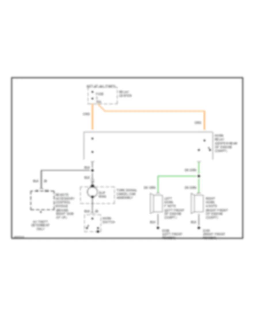
HORN
Horn Wiring Diagram for Pontiac Bonneville SE 1994
List of elements for Horn Wiring Diagram for Pontiac Bonneville SE 1994:
- Fuse 15a
- G100 (left front fender)
- G101 (right front fender)
- Horn relay (center rear of engine compt)
- Horn switch
- Hot at all times
- Left horn f note (left front of engine compt)
- Relay center
- Remote accessory control module (behind right side of i/p)
- Right horn a note (right front of engine compt)
- Slip ring
- Turn signal cancel cam assembly
- W/ theft deterrent only
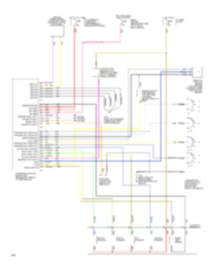
INSTRUMENT CLUSTER
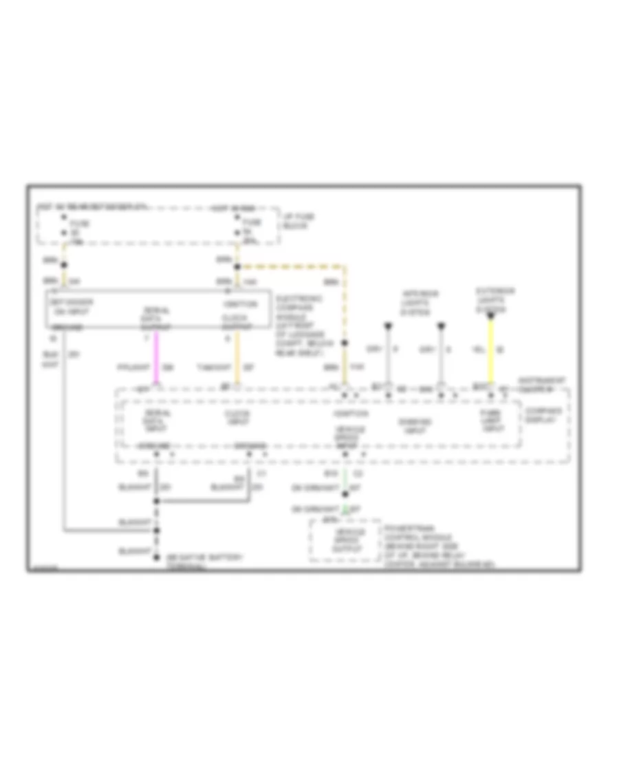
Electronic Compass Wiring Diagram for Pontiac Bonneville SE 1994
List of elements for Electronic Compass Wiring Diagram for Pontiac Bonneville SE 1994:
- B10
- B12
- B16
- Clock input
- Clock output
- Compass display
- D15
- Defogger on input
- Dimming input
- Electronic compass module (lh front of luggage compt, below rear shelf)
- Exterior lights system
- Fuse 3d 10a
- Fuse 5a 10a
- Ground
- Hot in run
- Hot w/ rear defogger on
- I/p fuse block
- Ignition
- Instrument cluster
- Interior lights system
- Park lamp input
- Powertrain control module (behind right side of i/p, behind relay center, against bulkhead)
- Serial data input
- Serial data output
- Vehicle speed input
- Vehicle speed output
Head-Up Display Wiring Diagram for Pontiac Bonneville SE 1994
List of elements for Head-Up Display Wiring Diagram for Pontiac Bonneville SE 1994:
-
- Bright
- Check gauges input
- Check gauges output
- D15
- Dim
- Display on/off input
- English/ metric input
- English/ metric switch
- Exterior lights system
- Fuse 5a 10a
- Fuse block: i/p
- G200 (below left side of i/p, middle of shroud)
- Ground
- Head-up display control module (behind left top of i/p)
- Head-up display control switch
- Headlights system
- Hi beam input
- Hot in run
- Ign
- Instrument cluster
- Interior lights system
- Lh turn input
- Low fuel input
- Low fuel output
- Off
- Powertrain control module (behind right side of i/p)
- Rh turn input
- Vehicle speed input
- Vehicle speed output
- Vf dim input
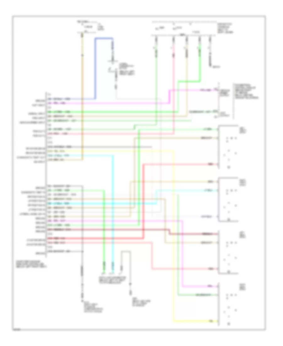
Instrument Cluster Wiring Diagram, Base for Pontiac Bonneville SE 1994
List of elements for Instrument Cluster Wiring Diagram, Base for Pontiac Bonneville SE 1994:
- (left front of engine compt)
- (not used)
- (top left side of engine)
- A12
- A13
- A16
- Abs ind. ctrl
- Acc
- Anti- lock diode
- Anti- lock ind.
- Antilock brakes system
- B1 volts ind. ctrl
- B10
- B10 ect ind. ctrl
- B11
- B12
- B16
- B17
- Brake fluid level switch
- Brake indicator
- Brake warning input
- Change oil ind.
- Check oil level ind.
- D13
- D15
- Diagnostic energy reserve module (behind i/p, right of accelerator pedal)
- Ects input
- Electronic brake control module (attached to left front strut tower)
- Engine controls system
- Engine coolant
- Engine coolant temp. gauge
- Engine coolant temperature ind.
- Engine coolant temperature sender (top left side of engine) (hot-55 ) (cold-1365 )
- Exterior lights system
- Fasten belts ind.
- Fasten belts ind. ctrl
- Fuel gauge
- Fuel gauge sender (on top of fuel tank) (full-90 ) (empty-0 )
- Fuse 1d 15a
- Fuse 5a 10a
- Fuse 8 10a
- Fuse 9c 10a
- Fuse block: i/p
- G100
- G200 (below left side of i/p)
- G203 (below right side of i/p)
- Gen input
- Gen output
- Generator
- Gnd
- Headlights system
- Hi beam ind.
- Hot at all times
- Hot in run
- Hot in run, bulb test or start
- Ignition switch
- Illumination (9 bulbs)
- Infl. rest. ind.
- Instrument cluster
- Interior lights system
- Left turn ind.
- Lock
- Low oil level output
- Low oil level sensor (lower left front of engine)
- Malfunction ind.
- Master cylinder reservoir
- Mil ind. ctrl
- Multi-function chime module (behind i/p, right of steering column)
- Nca
- Odometer
- Off
- Oil level module (behind right side of i/p)
- Oil pressure ind.
- Oil pressure switch (lower right rear of engine) (open with normal oil pressure )
- Park brake switch (opens with park brake released)
- Pass- key ii decoder module (behind top right side of i/p)
- Pnk
- Pnk a15
- Pnk a6
- Pnk b2
- Pnk b4
- Power
- Powertrain control module (behind right side of i/p)
- Red
- Relay center
- Remote accessory control module (behind right side of i/p)
- Right turn ind.
- Run
- Security ind.
- Security ind. ctrl
- Sensor return
- Signal output
- Sir ind. ctrl
- Solid state driver/ logic
- Speedometer
- Start bulb test
- Tan
- Temperature sensor
- Traction off ind.
- Vehicle speed output
- Volts ind.
- With ua6 only
Instrument Cluster Wiring Diagram, Gauges, U2F & U50 for Pontiac Bonneville SE 1994
List of elements for Instrument Cluster Wiring Diagram, Gauges, U2F & U50 for Pontiac Bonneville SE 1994:
- (left front of engine compt)
- (not used)
- (top left side of engine)
- (u2f only)
- (u2f)
- (u50) voltage level in
- 5 volt output
- A11
- A12
- A13
- A15
- A16
- Abs ind. ctrl
- Acc
- Adaptive lamp monitor module (behind i/p, right of steering column)
- Anti- lock diode
- Anti- lock ind.
- Antilock brakes system
- B1 volt ind. ctrl
- B10
- B11
- B12
- B13
- B14
- B15
- B16
- B17
- B4 red l
- B6 serial data request
- Boost gauge
- Boost/ map sensor (top left rear of engine) (with l67 sc engine only)
- Brake fluid level switch
- Brake indicator
- Brake warning diode
- Brake warning input
- Check gauges input
- Check gauges output
- Chime control output
- Clock
- Clock output
- Compass display
- D13
- D15
- Data
- Diagnostic energy reserve module (behind i/p, right of accelerator pedal)
- Digital engine coolant temperature sender (top left side of engine) (hot-40 ) (cold-1365 )
- Ects input
- Ects output
- Electronic brake & traction control module (attached to left front strut tower)
- Electronic compass module (left front of luggage compt)
- Electronic ignition module (top right front of engine)
- Enable input a2
- Engine controls system
- Engine coolant
- Engine coolant temper- ature gauge
- Engine speed output
- Exterior lights system
- Fasten belts ind.
- Fasten belts ind. ctrl
- Fuel gauge
- Fuel gauge sender (top of fuel tank) (full-88 ) (empty-1 )
- Fuse 1d 15a
- Fuse 4a 10a
- Fuse 5a 10a
- Fuse 8 10a
- Fuse 9c 10a
- Fuse block: i/p
- G100
- G200 (below left side of i/p)
- G203 (below right side of i/p)
- G402 (left rear of luggage compt, behind wheelhouse)
- Gen in
- Gen out
- Generator
- Gnd
- Head up display control module (behind top left of i/p)
- Headlamp washer module
- Headlights
- Hi beam ind.
- High coolant temperature input
- Hood ajar input
- Hood ajar switch (on left radiator support)
- Hot at all times
- Hot in run
- Hot in run, bulb test or start
- Hot with lamp switch in park or head
- Ign 3
- Ign. input
- Ignition switch
- Illum. lamps
- Illumi- nation (8 bulbs)
- Infl. rest. ind.
- Instrument cluster
- Interior lights system
- Left front door ajar input
- Left front door lock assy
- Left rear door ajar input
- Left rear door latch assy
- Left turn ind.
- Lock
- Low coolant level input
- Low coolant level output
- Low coolant level sensor (lower right rear of radiator)
- Low fuel input
- Low fuel output
- Low oil level input
- Low oil level output
- Low oil level sensor (lower left front of engine)
- Low washer fluid level input
- Luggage compt lamp/ ajar switch (center rear of luggage compt)
- Luggage compt lid ajar input
- Malfunction ind.
- Master cylinder reservoir
- Mil ind. ctrl
- Multi- function chime module (behind i/p, right of steering column)
- Multi-function chime module (behind i/p, right of steering column)
- Nca
- Odometers
- Off
- Oil gauge pressure sender (3800-lower right rear of engine) (l67 sc-lower right side of engine) (high-84 ) (low-17 )
- Oil level module (behind right side of i/p)
- Oil pressure gauge
- Park brake switch (opens with park brake released)
- Pass- key ii decoder module (behind top right side of i/p)
- Pnk
- Pnk a10
- Power
- Powertrain control module (behind right side of i/p)
- Red
- Relay center
- Remote accessory control module (behind right side of i/p)
- Right front door ajar input
- Right front door lock assy
- Right rear door ajar input
- Right rear door latch assy
- Right turn ind.
- Run
- Security ind.
- Security ind. ctrl
- Sensor return
- Serial data input
- Serial data output
- Signal input
- Signal output
- Sir ind. ctrl
- Solid state
- Solid state driver/ logic
- Spare bulb 1
- Spare bulb 2
- Speedometer
- Start bulb test
- System
- Tachometer
- Tan
- Temperature sensor
- Traction off ind.
- Traction off ind. ctrl
- Variable vf dimming input
- Vehicle speed output
- Vf dim input
- Volt ind.
- Voltmeter (u50 only)
- Washer fluid level switch (in windshield washer fluid reservoir)
- With ua6 only
Instrument Cluster Wiring Diagram, Gauges, UB3 for Pontiac Bonneville SE 1994
List of elements for Instrument Cluster Wiring Diagram, Gauges, UB3 for Pontiac Bonneville SE 1994:
- (left front of engine compt)
- (not used)
- (top left side of engine)
- 5 volt regulator
- A11
- A12
- A13
- A16
- Abs ind. ctrl
- Acc
- Anti- lock diode
- Anti- lock ind.
- Antilock brakes system
- B10
- B11
- B12
- B13
- B15
- B16
- B17
- Brake fluid level switch
- Brake indicator
- Brake warning diode
- Brake warning input
- Change oil ind.
- Check gauges ind.
- Check oil level ind.
- Chime ctrl out
- D13
- D15
- Diagnostic energy reserve module (behind i/p, right of accelerator pedal)
- Ects input
- Electronic brake & traction control module (attached to left front strut tower)
- Electronic ignition module (top right front of engine)
- Engine controls system
- Engine coolant
- Engine coolant temp. gauge
- Engine coolant temperature sender (top left side of engine) (hot-55 ) (cold-1365 )
- Engine speed output
- Exterior lights system
- Fasten belts ind.
- Fasten belts ind. ctrl
- Fuel gauge
- Fuel gauge sender (on top of fuel tank) (full-90 ) (empty-0 )
- Fuse 1d 15a
- Fuse 5a 10a
- Fuse 8 10a
- Fuse 9c 10a
- Fuse block: i/p
- G100
- G200 (below left side of i/p)
- G203 (below right side of i/p)
- Gen input
- Gen output
- Generator
- Gnd
- Headlights system
- Hi beam ind.
- Hot at all times
- Hot in run
- Hot in run, bulb test or start
- Ignition switch
- Illumination (9 bulbs)
- Infl. rest. ind.
- Instrument cluster
- Interior lights system
- Left turn ind.
- Lock
- Low oil level output
- Low oil level sensor (lower left front of engine)
- Malfunction ind.
- Master cylinder reservoir
- Mil ind. ctrl
- Multi-function chime module (behind i/p, right of steering column)
- Nca
- Odometer
- Off
- Oil level module (behind right side of i/p)
- Oil pressure gauge
- Oil pressure sender (lower right rear of engine) (high-90 ) (low-0 )
- Park brake switch (opens with park brake released)
- Pass- key ii decoder module (behind top right side of i/p)
- Pnk
- Pnk a15
- Pnk a6
- Pnk b2
- Pnk b4
- Power
- Powertrain control module (behind right side of i/p)
- Red
- Relay center
- Remote accessory control module (behind right side of i/p)
- Right turn ind.
- Run
- Security ind.
- Security ind. ctrl
- Sensor return
- Signal output
- Sir ind. ctrl
- Solid state
- Solid state driver/ logic
- Solid state driver/logic
- Speedometer
- Start bulb test
- Tachometer
- Tan
- Temperature sensor
- Traction off ind.
- Traction off ind. ctrl
- Vehicle speed output
- Voltmeter
- Washer fluid ind.
- Washer fluid level switch (in windshield washer fluid reservoir)
- With ua6 only
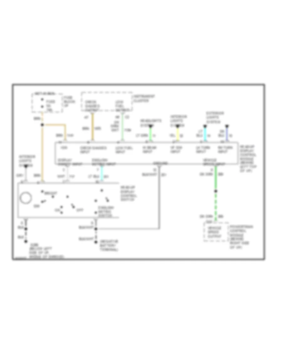
Lamp Monitor Wiring Diagram for Pontiac Bonneville SE 1994
List of elements for Lamp Monitor Wiring Diagram for Pontiac Bonneville SE 1994:
- A6 ign
- Adaptive lamp monitor module (behind i/p, right of steering column)
- Back up lamps sense
- Brake switch input
- Enable input
- Exterior lights system
- Fuse 5a 10a
- Fuse 9c 15a
- Fuse block: i/p
- Headlights system
- Hi beam input
- Hi beam sense
- Hi level stop lamp sense
- Hot at all times
- Hot in run
- Instrument cluster
- Left front park/side marker lamps sense
- Left front turn signal input
- Left front turn signal sense
- Left rear turn signal input
- Left rear turn signal sense
- Lo beam input
- Lo beam sense
- Memory input
- Park lamps input
- Park lamps input tail/ turn lamps sense
- Park/neutral position switch input
- Pnk
- Rear side marker/ lamps sense
- Right front park/side marker lamps sense
- Right front turn signal input
- Right front turn signal sense
- Right rear turn signal input
- Right rear turn signal sense
- Serial data input
- Serial data output
- Serial data request
- Stop lamps sense
- Tail lamps sense
- Tan
INTERIOR LIGHTS
Courtesy Lamp Wiring Diagram, without Illuminated Entry for Pontiac Bonneville SE 1994
List of elements for Courtesy Lamp Wiring Diagram, without Illuminated Entry for Pontiac Bonneville SE 1994:
- (left kickpad)
- (left side of engine compt above left horn)
- (left side of luggage compartment)
- (right kickpad)
- 1995 vftc c
- A nca
- Base only
- Console shift lamp
- Cover switch
- Engine compartment lamp
- Front dome/ reading lamp
- Fuse 1d 15a
- Fuse 4a 10a
- Fuse 6a 15a
- Fuse 9c 10a
- G100
- G200
- G200 (left kickpad)
- G203
- G404
- Glove- box lamp
- Glovebox lamp switch
- Head/ park lamp switch
- Hot at all times
- Hot in run, bulb test, or start
- Hot w/ head/ park lamp switch on
- I/p fuse block
- Junction connector c340 (left front door sill, taped to harness)
- Left door flood lamp
- Left foot- well courtesy lamp
- Left front door courtesy lights
- Left front door lock assembly
- Left front vanity mirror
- Left rail lamp
- Left rear door courtesy lamps
- Left rear door latch assembly
- Luggage compart- ment lamp
- Luggage compart- ment latch switch
- Nca
- Pnk
- Right door flood lamp
- Right foot- well courtesy lamp
- Right front door courtesy lights
- Right front door lock assembly
- Right front vanity mirror
- Right rail lamp
- Right rear door courtesy lamps
- Right rear door latch assembly
- Uplevel only
Courtesy Lamps Wiring Diagram, with Illuminated Entry for Pontiac Bonneville SE 1994
List of elements for Courtesy Lamps Wiring Diagram, with Illuminated Entry for Pontiac Bonneville SE 1994:
- (left kickpad)
- (left side of engine compt above left horn)
- (left side of luggage compartment)
- (right kickpad)
- 1995 vftc c
- A nca
- Base only
- Battery
- C nca
- Console shift lamp
- Cover switch
- Door input
- Engine compartment lamp
- Front dome/ reading lamp
- Fuse 15a
- Fuse 1d 15a
- Fuse 4a 10a
- Fuse 6a 15a
- Fuse 9c 10a
- G100
- G200
- G200 (left kickpad)
- G203
- G203 (right kickpad)
- G404
- Glove- box lamp
- Glovebox lamp switch
- Ground
- Handle inpt
- Head/ park lamp switch
- Hot at all times
- Hot in run, bulb test, or start
- Hot w/ head/ park lamp switch on
- I/p fuse block
- Ignition
- Interior lamps relay position f (in relay center)
- Junction connector c340 (left front door sill, taped to harness)
- Lamp ctrl
- Left door flood lamp
- Left foot- well courtesy lamp
- Left front door courtesy lights
- Left front door handle switch
- Left front door key cyl lamp
- Left front door lock assembly
- Left front vanity mirror
- Left rail lamp
- Left rear door courtesy lamps
- Left rear door latch assembly
- Luggage compart- ment lamp
- Luggage compart- ment latch switch
- Nca
- Pnk
- Pnk b
- Relay center
- Relay ctrl
- Remote accessory control module (behind right side of i/p)
- Right door flood lamp
- Right foot- well courtesy lamp
- Right front door courtesy lights
- Right front door handle switch
- Right front door key cyl lamp
- Right front door lock assembly
- Right front vanity mirror
- Right rail lamp
- Right rear door courtesy lamps
- Right rear door latch assembly
- Uplevel only
Instrument Illumination Wiring Diagram for Pontiac Bonneville SE 1994
List of elements for Instrument Illumination Wiring Diagram for Pontiac Bonneville SE 1994:
- (c61)
- (c68)
- Ashtray lamp
- B12
- C nca
- Console seat switch
- Control switch
- D nca
- Display control
- E nca
- Exterior lights system
- Fuse 4a 10a
- Fuse 6c 15a
- G200 (left kickpad)
- Gain
- Head
- Head up
- Head up display control module
- Head/ park lamp switch
- Head/park lamp switch
- Heater and a/c control assembly
- Hot at all times
- I/p fuse block
- Instrument cluster
- Junction connector c340 (left front door sill, taped to harness)
- Lamp control module (center of i/p)
- Nca
- Off
- Or traction control/ driver select switch
- Park
- Radio
- Sir coil assembly
- Steering wheel radio switches
- Switch
- Traction
- Vf dim input
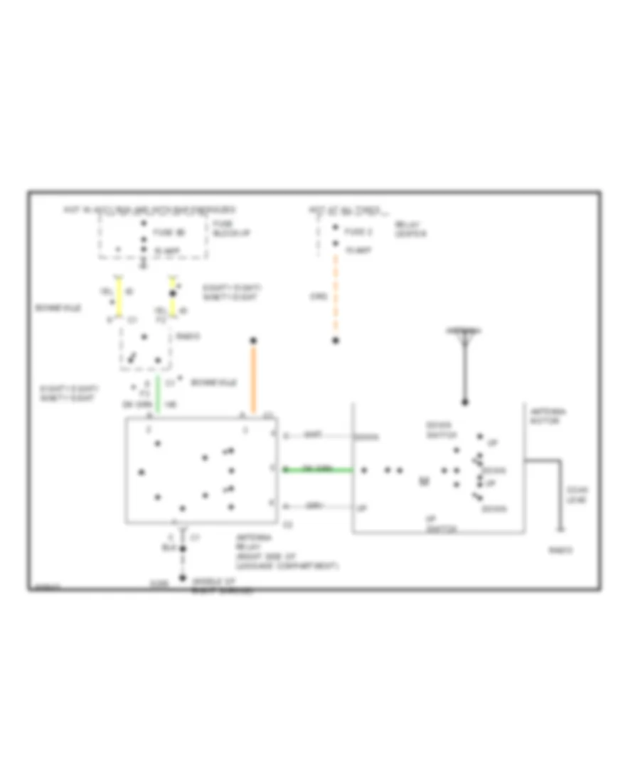
POWER ANTENNA
Power Antenna Wiring Diagram for Pontiac Bonneville SE 1994
List of elements for Power Antenna Wiring Diagram for Pontiac Bonneville SE 1994:
- (middle of right shroud)
- 10 amp
- 15 amp
- Antenna
- Antenna motor
- Antenna relay (right side of luggage compartment)
- Bonneville
- Coax lead
- Down
- Down switch
- Eighty eight/ ninety eight
- Fuse 2
- Fuse 8d
- Fuse block:i/p
- G203
- Hot at all times
- Hot in accy,run and with rap energized
- Radio
- Relay center
- Up switch
POWER DISTRIBUTION
Power Distribution Wiring Diagram (1 of 4) for Pontiac Bonneville SE 1994
List of elements for Power Distribution Wiring Diagram (1 of 4) for Pontiac Bonneville SE 1994:
- and hvac
- controls
- #8d
- #8e
- (i/p fuse
- (i/p fuse block)
- (left underhood
- 10a
- 15a
- 20a
- 25a
- 30a
- 40a
- 60a
- A/c
- Accessory
- Accy
- Alternator
- Antenna
- Auto
- Battery
- Block)
- Blower
- Blower ctrl
- Bulb
- Center
- Control
- Ctrl module
- Decoder
- Door isolation
- Door lock
- Express down
- From fuse #7
- From fuse #7 (left
- Fuse block
- Fuse block)
- Horn
- I/p fuse block
- Ignition sw
- Interior
- Left front
- Left rear
- Lid release
- Lock
- Lt rly
- Luggage compt
- Manual
- Master
- Module
- Nca
- Off
- Pass key
- Pnk
- Power
- Powertrain
- Radio
- Rap
- Rap rly
- Red
- Relay
- Remote
- Retained
- Right front
- Right rear
- Right underhood fuse block
- Rly
- Rly #1
- Rly #2
- Run
- Sol
- Start
- Starter
- Steering
- Sunroof ctrl
- Sw assy
- Test
- To fuse #17
- To fuse #1a
- To fuse #1b
- To left underhood
- Underhood fuse block)
- W / remote keyless entry
- W/ rap
- W/o
- Washer
- Wheel radio
- Window module
- Window sw
- Wiper/
Power Distribution Wiring Diagram (2 of 4) for Pontiac Bonneville SE 1994
List of elements for Power Distribution Wiring Diagram (2 of 4) for Pontiac Bonneville SE 1994:
- #6a
- #6b
- #6c
- #6d
- #9b
- #9c
- 10a
- 15a
- 20a
- 30a
- 40a
- 50a
- 60a
- Abs
- Accessory
- Adaptive lt
- Amplifier
- Assist
- Auxiliary
- Brake sw
- Brake/traction
- C13
- Chime module
- Cluster
- Compt
- Compt lt
- Connector
- Console
- Control
- Coolant
- Courtesy lt
- Courtesy lts
- Cruise/shift
- Ctrl module
- Ctrl sw
- Dome/courtesy/
- Elc
- Elc rly
- Electronic
- Fan rly
- Fiber optic lts
- Flasher
- Fog lt
- Footwell
- From right underhood
- Front door
- Fuse block
- Fuse block)
- Hazard
- Head/park
- Headlamp
- Height
- High speed
- Hvac
- I/p
- I/p fuse block
- Inflator
- Information center
- Instrument
- Interlock
- Left
- Left underhood fuse block
- Level
- Low speed
- Lt sw
- Luggage
- Main rly
- Mirror
- Module
- Monitor
- Multi-function
- Nca
- Oil
- Only
- Outside
- Park lamp
- Power rly #2
- Programmer
- Pump rly
- Radio
- Rail lts
- Reading lts
- Rear door
- Red
- Relay
- Right
- Seat sw
- Sens
- Speaker
- Sse
- Strap
- Timer-relay
- To cb #3 (i/p
- To fuse #9e (i/p
- To head/
- To ignition
- To lamp
- To retained
- Vanity
- W/ driver
- Washer
Power Distribution Wiring Diagram (3 of 4) for Pontiac Bonneville SE 1994
List of elements for Power Distribution Wiring Diagram (3 of 4) for Pontiac Bonneville SE 1994:
- sensor
- #18
- #3d
- #5a
- #5b
- #5c
- #5d
- #9e
- (left underhood
- (with left
- 10a
- 25a
- 30a
- A/c
- A/c control
- A/c temperature
- Adaptive lt
- And a/c
- Anti-lock
- Assembly
- Automatic
- Block
- Brake and
- Brake sw
- C12
- C16
- Cluster
- Command
- Compass
- Computer
- Control
- Control assembly
- Control sw
- Controller
- Coolant
- Defogger
- Display
- Driver
- Elc
- Electronic
- Elements
- Fan rly
- From
- From fuse #8
- Fuse
- Fuse block)
- Head up
- Heated mirror
- Heater
- Heater &
- Heater and a/c
- Height
- High speed
- Hvac
- I/p
- I/p fuse
- I/p fuse block
- Ignition
- Instrument
- Left
- Lh seat
- Low speed
- Lumbar
- Main
- Module
- Monitor
- Nca
- Not used
- Oil level
- Power
- Power seat only)
- Programmer
- Rear
- Red
- Relay
- Rh seat
- Ride
- Right
- Seat
- Select
- Shift
- Switch
- Tcc/
- Traction
- Transaxle
- Up display
- Valve actuator
- W/ head up
- W/ right
- W/o head
- With
- With electronic
- With manual
- With sport only
- Without
Power Distribution Wiring Diagram (4 of 4) for Pontiac Bonneville SE 1994
List of elements for Power Distribution Wiring Diagram (4 of 4) for Pontiac Bonneville SE 1994:
- sw
- #1a
- #1b
- #1c
- #1d
- #4a
- (d55)
- (digital)
- (i/p fuse block)
- (pcm)
- 10a
- 15a
- 20a
- A/c comp
- A10
- A15
- Accy ctrl
- And a/c
- And daytime running lights
- Assembly
- Automatic
- B10
- B12
- Block
- Boost sol
- Canister
- Center
- Chime module
- Cluster
- Compt lt
- Console
- Control
- Ctrl module
- Ctrl rly
- Day/night
- Decoder
- Diagnostic
- Display
- Door flood
- Dual pole arming
- Dual sensor (aj3)
- Electronic
- Emission
- Enable rly
- Energy reserve
- Engine
- Evaporative
- Exhaust gas
- Exterior
- Flasher
- Flow sens
- From
- Fuel
- Fuel injectors
- Fuse
- Fuse #6c
- Head
- Head up
- Head/
- Heated oxygen
- Heater
- I/p
- Ignition
- Instrument
- Lamp
- Lamp
- Lamp ctrl
- Left
- Lever
- Lts
- Mass air-
- Mirror
- Module
- Multi-function
- Nca
- Neutral
- Off
- Oil pres
- Park
- Park/
- Pass key
- Pnk
- Pnk
- Position
- Powertrain
- Pump rly
- Purge
- Radio
- Recirculation
- Remote
- Right
- Rly
- Sens
- Sens/sw
- Sensor (ak5)
- Shift lt
- Sol
- Sol valve
- Starter
- Steering
- Supercharged
- Tfe
- Turn
- Vac regulator
- W/ console
- W/ twilight sentinel
- W/ two flow
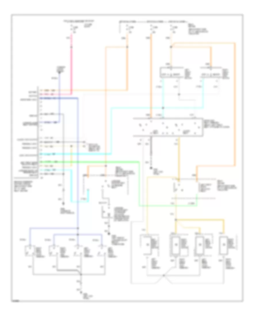
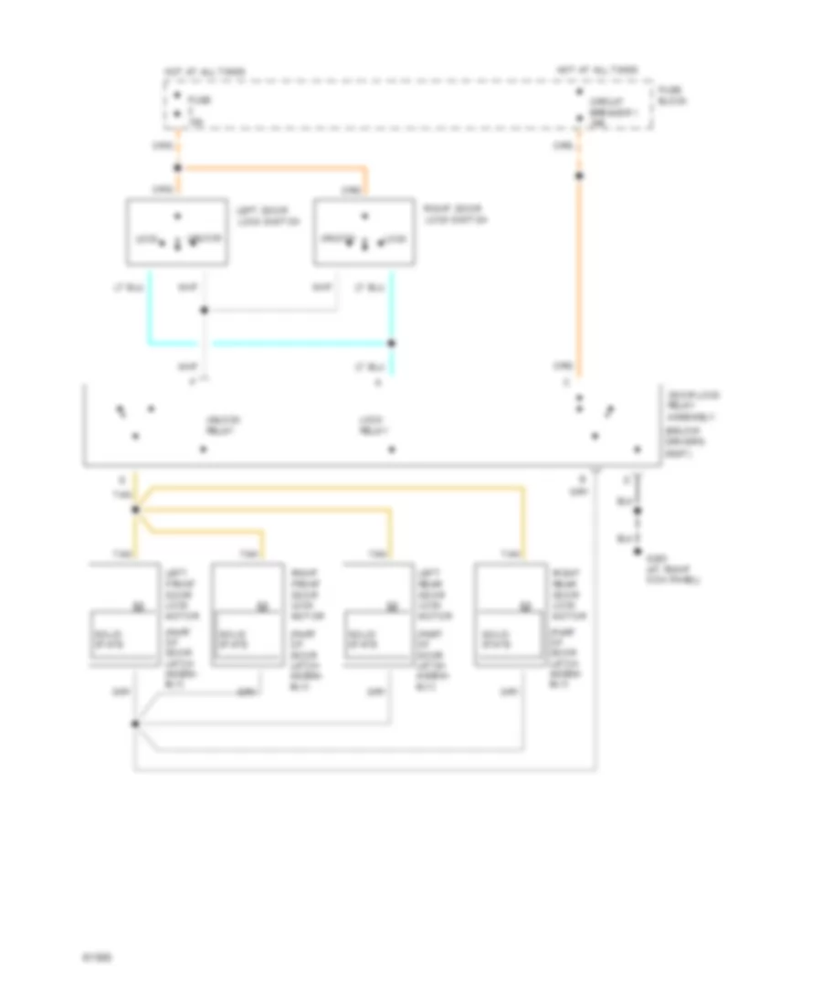
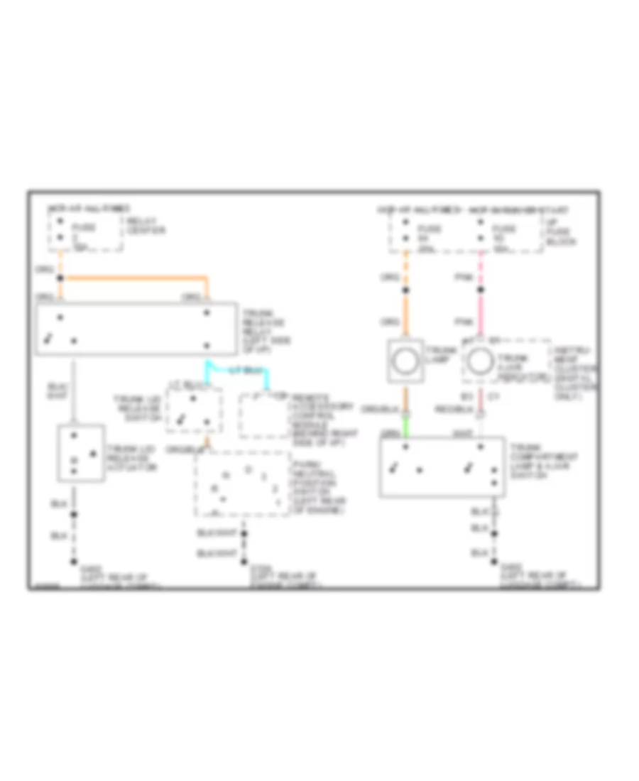
POWER DOOR LOCKS
Power Door Lock Wiring Diagram, with Remote/Keyless Entry for Pontiac Bonneville SE 1994
List of elements for Power Door Lock Wiring Diagram, with Remote/Keyless Entry for Pontiac Bonneville SE 1994:
- (behind right side of i/p, above sound insulator)
- 15a
- 20a
- Battery
- Data link connector (below left side of i/p)
- Door lock relay assembly (below left front seat, attached to floor)
- Door open input
- Fuse
- Fuse 1d
- G200 (left kick panel)
- G203 (middle of right shroud)
- G402 (left side of luggage compt behind wheelhouse)
- Ground
- Hot at all times
- Hot in run, bulb test or start
- I/p fuse block
- Ignition
- Interior lamps relay control
- Interior lights system
- Left front door isolation relay
- Left front door lock assembly
- Left front door lock motor
- Left front door lock switch
- Left rear door latch assembly
- Left rear door lock motor
- Lock
- Lock input/output
- Lock relay
- Luggage compartment lid release actuator (center rear of luggage compt lid, near latch)
- Luggage compartment lid release relay
- Luggage compt lid release relay
- Pnk
- Program input
- Relay center
- Relay center (behind right side of i/p, above sound insulator)
- Remote accessory control module (behind right side of i/p, near relay center)
- Right front door lock assembly
- Right front door lock motor
- Right front door lock switch
- Right rear door latch assembly
- Right rear door lock motor
- Tan
- Unlock
- Unlock input/output
- Unlock relay
Power Door Lock Wiring Diagram, without Remote/Keyless Entry for Pontiac Bonneville SE 1994
List of elements for Power Door Lock Wiring Diagram, without Remote/Keyless Entry for Pontiac Bonneville SE 1994:
- (below driver's seat)
- (part of door latch assem- bly)
- Assembly
- Circuit breaker 1 30a
- Door lock
- Fuse 15a
- Fuse block
- G203 (at right kick panel)
- Hot at all times
- Left door lock switch
- Left front door lock motor
- Left rear door lock motor
- Lock
- Lock relay
- Relay
- Right front door lock motor
- Right rear door lock motor
- Right door lock switch
- Solid state
- Tan
- Unlock
- Unlock relay
POWER MIRRORS
Power Mirror Wiring Diagram for Pontiac Bonneville SE 1994
List of elements for Power Mirror Wiring Diagram for Pontiac Bonneville SE 1994:
-
- nca
- (below left side of i/p, middle of shroud)
- Ambient light sensor (winshield side)
- Automatic day/night mirror
- D nca
- Down
- Drive unit
- Fuse 1b 20a
- Fuse 1d 15a
- Fuse 6a 15a
- G200
- G200 (below left side of i/p, middle of shroud)
- Ground
- Headlamp sensor (mirror side)
- High low sensitivity setting
- Hot at all times
- Hot in run, bulb test or start
- I/p fuse block
- Left
- Left outside mirror assembly
- Left/ right mirror motor
- Max
- Min
- Mirror position switch
- Mirror select switch
- Mirror switch
- Nca
- Off
- On indicator control
- Outside mirror control switch
- Pnk
- Reset to daytime high reflectivity in reverse
- Right
- Right outside mirror assembly
- Sensitivity setting
- Solid state
- Transaxle range switch
- Up/down mirror motor
POWER SEATS
Power Seat Wiring Diagram for Pontiac Bonneville SE 1994
List of elements for Power Seat Wiring Diagram for Pontiac Bonneville SE 1994:
- Circuit breaker 3 25a
- D tan d tan
- E tan d tan
- Entire seat back
- Entire seat down
- Entire seat forward
- Entire seat up
- Forward/back motor
- Front height down
- Front height motor
- Front height up
- G200 (below left side of i/p, middle of shroud)
- G203 (below right side of i/p, middle of shroud)
- Hot at all times
- I/p fuse block
- Left seat
- Left seat switch
- Rear height down
- Rear height motor
- Rear height up
- Right seat
- Right seat switch
- Solid state
Sport Seats Wiring Diagram (1 of 2) for Pontiac Bonneville SE 1994
List of elements for Sport Seats Wiring Diagram (1 of 2) for Pontiac Bonneville SE 1994:
- Air pump
- Back
- Bat
- Battery
- C2 nca
- Circuit breaker 3 25a
- Console switch input
- Deflate relay
- For/back motor relay
- Forward
- Forward/back motor
- Front tilt down
- Front tilt motor
- Front tilt up
- G200 (below left side of i/p, middle of shroud)
- Ground
- Hot at all times
- I/p fuse block
- Inflate relay
- L/r select relay
- Left forward/ back motor
- Left front seat
- Left front tilt motor
- Left rear tilt motor
- Left recliner motor
- Left/right select
- Lumbar control module (under driver's seat)
- Nca
- Nca d
- Pnk
- R/l select relay
- Rear tilt down
- Rear tilt motor
- Rear tilt up
- Recline back
- Recline up
- Recliner motor
- Recliner motor relay
- Right forward/ back motor
- Right front seat
- Right front tilt motor
- Right rear tilt motor
- Right recliner motor
- Seat air pump assembly
- Seat control module (under driver's seat)
- Tan
Sport Seats Wiring Diagram (2 of 2) for Pontiac Bonneville SE 1994
List of elements for Sport Seats Wiring Diagram (2 of 2) for Pontiac Bonneville SE 1994:
- Back
- Console seat switch
- Def
- Entire seat up/down
- F c2
- For
- Forward/ back
- Front tilt
- Fuse 8a 15a
- G200 (below left side of i/p, middle of shroud)
- Hot at all times
- I/p fuse block
- Inf
- Interior lights system
- Left
- Left seat solenoid valve assembly
- Lower lumbar
- Middle lumbar
- Nca
- Nca d
- Off
- Panel lamps
- Pnk
- Pnk h
- Rear tilt
- Recline
- Right
- Right seat solenoid valve assembly
- Seat select switch
- Side bolster
- Side bolsters
- Tan
- Upper lumbar
POWER TOP/SUNROOF
Power Top/Sunroof Wiring Diagrams for Pontiac Bonneville SE 1994
List of elements for Power Top/Sunroof Wiring Diagrams for Pontiac Bonneville SE 1994:
- Actuator
- C 1994 vftc
- Circuit breaker 1 30a
- Control
- Forward/ vent
- Forward/vent
- Fuse block: i/p
- G201 (right kick panel)
- Ground
- Hot in run, bulb test or start & w/ rap energized
- Ignition
- Input
- Limit switch
- Limit switch input
- Red
- Reverse/ close vent
- Reverse/close vent
- Sunroof actuator assembly (center of windshield header)
- Sunroof control module (right side of roof, behind "a" pillar)
- Sunroof switch
POWER WINDOWS
Power Window Wiring Diagram for Pontiac Bonneville SE 1994
List of elements for Power Window Wiring Diagram for Pontiac Bonneville SE 1994:
- (behind left kick panel)
- 30a
- C 1994 vftc
- Circuit breaker 1
- Express down window module (driver's door)
- G200
- Hot in run, bulb test or start and with rap energized
- I/p fuse block
- Left front window motor
- Left rear window motor
- Left rear window switch
- Master switch assembly
- Right front window motor
- Right front window switch
- Right rear window motor
- Right rear window switch
- Solid state
- Tan
RADIO
Radio Wiring Diagrams, with Amplifier for Pontiac Bonneville SE 1994
List of elements for Radio Wiring Diagrams, with Amplifier for Pontiac Bonneville SE 1994:
- (body harn, behind center of dash) s901
- (body harn, behind center of dash) s903
- (body harn, behind center of dash) s906
- Antenna
- Antenna enable
- Audio amplifier (under center of dash, near back of radio)
- Battery voltage
- Coaxial cable
- Computer data lines system
- Display dimming
- Enable
- Fuse 8d 10a
- Fuse 9c 10a
- G200 (left kick panel)
- Gain control switch
- Gain input
- Gain output
- Ground
- Hot at all times
- Hot in run, acc or w/ retained accessory power
- I/p fuse block (behind left side of dash, on dash panel sound insulator)
- Ign voltage
- Inflatable restraint steering wheel module coil
- Interior lights system
- Left lower front door speaker
- Left rear speaker (sub woofer)
- Left rear speaker (tweeter)
- Left upper front door speaker
- Lf chnl out (+)
- Lf chnl out (-)
- Lr chnl out (+)
- Lr chnl out (-)
- Lr subw out (+)
- Lr subw out (-)
- Nca
- Pnk
- Power antenna system
- Radio
- Radio on input
- Rf chnl out (+)
- Rf chnl out (-)
- Right lower front door speaker
- Right rear speaker (sub woofer)
- Right rear speaker (tweeter)
- Right upper front door speaker
- Rr chnl out (+)
- Rr chnl out (-)
- Rr subw out (+)
- Rr subw out (-)
- S213
- S214
- S408
- S409
- S410
- S440
- S900 (body harn, behind center of dash) s902
- S904 (body harn, behind center of dash)
- S907 s905 (body harn, behind center of dash)
- Serial data e&c
- Steering wheel control switch
- Strg whl ctlr
- Sw1
- Sw2
- Sw3
- Sw4
- Sw5
- Sw6
- Sw7
- Sw8
- Tan
Radio Wiring Diagrams, without Amplifier for Pontiac Bonneville SE 1994
List of elements for Radio Wiring Diagrams, without Amplifier for Pontiac Bonneville SE 1994:
- Antenna
- Antenna enable
- Battery voltage
- Coaxial cable
- Computer data lines system
- Display dimming
- G200 (left kick panel)
- Ground
- Hot at all times
- Hot in run, acc or w/ retained accessory power
- I/p fuse block (behind left side of dash, on dash panel sound insulator)
- Ign voltage
- Inflatable restraint steering wheel module coil
- Interior lights system
- Left front door speaker
- Left lower front door speaker
- Left rear speaker
- Left upper front door speaker
- Lf chnl out (+)
- Lf chnl out (-)
- Lr chnl out (+)
- Lr chnl out (-)
- Misc/ rdo/clstr fuse 9c 10a
- Nca
- Power antenna system
- Radio
- Radio fuse 8d 10a
- Rf chnl out (+)
- Rf chnl out (-)
- Right front door speaker
- Right lower front door speaker
- Right rear speaker
- Right upper front door speaker
- Rr chnl out (+)
- Rr chnl out (-)
- S203
- S213
- S214
- Serial data e&c
- Steering wheel control switch
- Strg whl ctlr
- Sw1
- Sw2
- Sw3
- Sw4
- Sw5
- Sw6
- Sw7
- Sw8
- Tan
- W/ uw6 (6 speaker system)
- W/ ux7 (4 speaker system)
SHIFT INTERLOCKS
Shift Interlock Wiring Diagram for Pontiac Bonneville SE 1994
List of elements for Shift Interlock Wiring Diagram for Pontiac Bonneville SE 1994:
- C107
- Cruise/shift interlock/ brake switch (brake pedal support)
- Fuse 20a
- G200 (middle of left shroud)
- Hot in run and with rap energized
- I/p fuse block
- Nca a
- Park/ neutral position switch (left side of transaxle)
- Pnk
- Shift interlock solenoid (w/console: below center console) (w/o console: base of steering column)
STARTING/CHARGING
Charging Wiring Diagram for Pontiac Bonneville SE 1994
List of elements for Charging Wiring Diagram for Pontiac Bonneville SE 1994:
- *u2e/ub3 clusters **u50/u2f clusters
- a13, b13
- (not used)
- (not used) p
- (right front of engine compt, above right horn)
- (top right front of engine, under ei module)
- 15a
- Bat
- Battery
- Field (rotor)
- Fuse 1d
- G101
- G119
- Gen ctrl
- Generator (top right side of engine)
- Ground distribution
- Hot in run, bulb test or start
- I/p fuse block
- Instrument cluster
- Low voltage input
- Pnk
- Pnk a6, a7
- Pnk b2
- Power distribution
- Powertrain control module (behind right side of i/p, near shroud)
- Rectifier bridge
- Red
- Regulator
- Solid state
- Starter solenoid (lower left front of engine)
- Stator
- U2e/u2f clusters
- Ub3/u50 clusters
- Volt ind.
- Volts lp
Starting Wiring Diagram for Pontiac Bonneville SE 1994
List of elements for Starting Wiring Diagram for Pontiac Bonneville SE 1994:
- (left front of engine compt, on radiator support)
- (lower left front of engine)
- Accy
- Battery
- Bulb test
- G108
- G110
- Hold-in coil
- Ign sw1 maxi- fuse 40a
- Ign sw2 maxi- fuse 40a
- Ignition switch
- Lock
- Nca
- Off
- Power distribution
- Pull-in coil
- Red
- Remote battery stud (at u/h electrical center #2)
- Run
- Solenoid contacts
- Start
- Starter assembly (lower front of engine)
- Starter enable
- Starter motor
- Theft deterrent module (behind left side of i/p, left of steering column)
- Theft deterrent relay (behind right side of i/p)
- Transaxle range switch (left of engine, on transaxle)
- Underhood electrical center #2
SUPPLEMENTAL RESTRAINTS
Supplemental Restraint Wiring Diagram for Pontiac Bonneville SE 1994
List of elements for Supplemental Restraint Wiring Diagram for Pontiac Bonneville SE 1994:
- (u2e & ub3) (u50 & u2f)
- (u50 & u2f) (u2e & ub3)
- 10.2k
- 2.49k
- 8.45k
- A10
- A11
- A12
- A7 b2
- B10
- B11
- B12
- B12 a6
- Computer data lines
- Crank input
- Diagnostic energy reserve module (derm) (behind center i/p, right side of accelerator pedal)
- Driver 36v lr
- Driver inflator module (in steering wheel pad)
- Driver side "high"
- Driver side "low"
- Driver source sense
- Dual pole arming sensor (behind left side i/p, attached to steering column support bracket)
- Forward discriminating sensor (center front of vehicle)
- Fuse 1a 10a
- Fuse 1c 10a
- Fuse 1d 15a
- G119 (right side of engine, under electronic ignition module)
- G200 (below left side of i/p, middle of shroud)
- G203 (right kick panel)
- Ground
- Hot in run or start
- Hot in start
- I/p fuse block
- Ign 1
- Inflatable restraint ind
- Instrument cluster
- Left mid-rail discriminating sensor (below front fender, attached to frame rail)
- Mult-function chime module (behind right side of i/p, on relay center bracket)
- Nca
- Pass 36v lr
- Pass side "high"
- Pass side "low"
- Pass source sense
- Passenger inflator module (right side of i/p, above i/p compt)
- Pnk
- Redundant ind ground
- Redundant ind ign 1
- Right mid-rail discriminating sensor (below front fender, attached to frame rail)
- Seat belt monitor
- Seat belt sw
- Seatbelt warning input
- Serial data
- Shorting bar
- Sir coil assembly (top center of steering column)
- Sir ind
- Tan
TRANSMISSION
Transmission Wiring Diagram, 4T60-E for Pontiac Bonneville SE 1994
List of elements for Transmission Wiring Diagram, 4T60-E for Pontiac Bonneville SE 1994:
- (left rear of engine, left side of transaxle)
- 5 volt ref
- Automatic transaxle
- B11
- B12
- B13
- B14
- Battery
- Brake input
- Brake switch input
- C11
- C12
- C14
- Cruise control system
- Cruise on input
- Cts
- Data link connector (below left side of i/p)
- Diagnostic input
- E12
- E13
- E14
- E15
- Engine coolant temp sensor (top left side of engine behind throttle body)
- F11
- F13
- F14
- Fuse 10a
- Fuse 20a
- Fuse 5c 10a
- G119 (right front of engine under electronic ignition module)
- G119 (right frt of engine under electronic ignition module)
- Ground
- Hot at all times
- Hot in run
- Hot in run, bulb test or start
- I/p fuse block
- Ign feed
- Nca
- Park/neutral
- Park/neutral postn sw
- Pnk
- Position switch
- Powertrain control module (pcm) (behind right side of i/p, near shroud)
- Red
- Relay center (behind right side of i/p, top of right shroud)
- Resume/accel input
- Rh underhood fuse block (center rear of engine compartment)
- Sensor ground
- Sensor return
- Shift a sol ctrl
- Shift a solenoid
- Shift b sol ctrl
- Shift b solenoid
- Tan
- Tcc pwm sol control
- Tcc pwm solenoid
- Tcc sol control
- Tcc solenoid
- Tcc/antilock brake switch (behind left side of i/p, on brake pedal support)
- Throttle position sensor (top left side of engine, under mass air flow sensor)
- Tps
- Trans temp in
- Trans temp sensor
- Vehicle speed sensor (lower right rear of engine, left of oil filter)
- Vss in-hi
- Vss in-lo
TRUNK, TAILGATE, FUEL DOOR
Trunk Release Wiring Diagram for Pontiac Bonneville SE 1994
List of elements for Trunk Release Wiring Diagram for Pontiac Bonneville SE 1994:
- Fuse 15a
- Fuse 1d 15a
- Fuse 6a 15a
- G104 (left rear of engine compt)
- G402 (left rear of luggage compt)
- Hot at all times
- Hot in run or start
- I/p fuse block
- Instru- ment cluster (digital cluster only)
- Park/ neutral position switch (left rear of engine)
- Pnk
- Relay center
- Remote accesssory control module (behind right side of i/p)
- Trunk ajar indicator
- Trunk compartment lamp & ajar switch
- Trunk lamp
- Trunk lid release actuator
- Trunk lid release switch
- Trunk release relay (left side of i/p)
WARNING SYSTEMS
Warning System Wiring Diagrams for Pontiac Bonneville SE 1994
List of elements for Warning System Wiring Diagrams for Pontiac Bonneville SE 1994:
- (steering column ground)
- (u2e or ub3 cluster) (u50 or u2f cluster)
- B3 a14
- B8 a12
- Bat
- Blt ind
- Blt sw
- Brake warning diode
- D15
- Dr sw
- Electronic power steering system
- Eps
- Fasten belts indicator
- Fuse 1d 15a
- Fuse 9c 10a
- Fuse block: i/p
- G200 (left kick panel)
- Gauges
- Gnd
- Head
- Head/ park lamp switch
- Hot at all times
- Hot in run, bulb test or start
- Ign
- Ign key sw
- Ignition key warning switch (in steering column)
- Indi- cators
- Instrument cluster
- Instrument cluster system
- Left front door lock assem- bly
- Lps on sig
- Multi- function chime module (below left side of i/p)
- Nca
- Off
- Park
- Park brake switch (below left side of i/p above park brake pedal)
- Pnk
- Powertrain control module (behind right side of i/p)
- Prk bk sw
- Safety belt switch (base of left b pillar)
- Tan
- Veh spd
WIPER/WASHER
Headlamp Washer Wiring Diagram for Pontiac Bonneville SE 1994
List of elements for Headlamp Washer Wiring Diagram for Pontiac Bonneville SE 1994:
- Bat
- E11
- Fuse 60a
- Fuse 8e 25a
- Fuse block
- G100 (left side of eng compt, above horn)
- Headlamp wash
- Headlamp washer spray input
- Headlight washer module (left side of eng compt)
- Headlight washer motor (left side of eng compt)
- Hot in accy or run
- Hot in run
- Nca
- Red
- Relay control
- Solid state timer/relay
- Washer fluid level switch (in washer reservoir)
- Washer headlamp disable input
- Washer/ wiper switch
- Windshield wash
Interval Wiper/Washer Wiring Diagram for Pontiac Bonneville SE 1994
List of elements for Interval Wiper/Washer Wiring Diagram for Pontiac Bonneville SE 1994:
- Cover assembly
- Fuse #25 pontiac fuse #8e (buick & olds) 25a
- G100 (left side of eng compt, above horn)
- Hot in accy or run
- I/p fuse block
- Mechanical arm
- Mist
- Off
- Park switch
- Pnk
- Pulse
- Pulse delay
- Red
- Solid state timer
- Washer motor (on washer reservoir)
- Washer switch
- Wiper motor module
- Wiper switch
- Wiper/ washer switch

 Čeština
 Dansk
Dansk Deutsch
 Ελληνικά
 English
 English
 Español
 Suomi
Suomi Français
 Français
 עברית
עברית Hrvatski
 Magyar
 Italiano
 日本語
日本語 한국어
한국어 Nederlands
 Polski
 Português
 Português
 Русский
 Slovenčina
 Slovenščina
 Svenska
 Türkçe
 中文 (中国)