AIR CONDITIONING
Compressor Wiring Diagram for Saturn Sky 2007
 https://portal-diagnostov.com/license.html
Automotive Electricians Portal FZCO
Automotive Electricians Portal FZCO
https://portal-diagnostov.com/license.html
https://portal-diagnostov.com/license.html
Automotive Electricians Portal FZCO
Automotive Electricians Portal FZCO
List of elements for Compressor Wiring Diagram for Saturn Sky 2007:
- (or tan)
- 2.0l
- 2.4l
- 5v ref 2
- A/c cltch relay
- A/c comp clutch rly ctrl
- A/c compressor clutch (at left front corner of engine, behind a/c compressor pulley)
- A/c fuse 22 10a
- A/c ref pr sens sig
- A/c refrigerant pressure sensor (at top left side of engine, near throttle body)
- Brake booster vacuum sensor (2.0l) (on brake vacuum booster)
- C1 d3
- C3 c5
- Computer data lines system
- D12
- Data bus (+)
- Data bus (-)
- Engine control module (ecm) (at left rear corner of engine compt, near brake master cylinder)
- F10
- G101 (at left front corner of engine compt, mounted on frame rail)
- Hot at all times
- Low ref
- Pwr/trn relay 26
- S102 (approximately 15 cm from brake fluid level switch breakout)
- S103 (approximately 10 cm from outside air temperature sensor breakout)
- S110 (approximately 10 cm from brake fluid level switch breakout)
- Tan
- Underhood fuse block (in right rear corner of engine compt)
2.0L VIN M TURBO
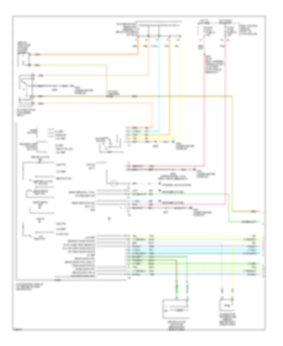
2.0L VIN M Turbo, Manual A/C Wiring Diagram (1 of 2) for Saturn Sky 2007
List of elements for 2.0L VIN M Turbo, Manual A/C Wiring Diagram (1 of 2) for Saturn Sky 2007:
- (behind right side of dash) blower motor
- (in hvac harness) s225
- 5v ref
- A/c ind
- A/c request sig
- A/c sw sig
- A/c switch
- Air temp door ctrl
- Air temp door pos sig
- Aux air temp door pos sig
- Batt
- Blower motor high speed relay
- Blower motor resistor assembly (below blower motor)
- Blower switch
- Body control module (right of hvac module)
- Defogger system
- Defrost door pos sig
- Evap core temp sens sig
- Evaporator temperature sensor (behind right side of dash)
- G300 (under center console)
- Gnd
- Hot at all times
- Hot in run or start
- Hvac control module (at center of dash, above radio)
- Hvac/ ip ign fuse 16 10a
- Hvac/ pk3 + fuse 10 10a
- Ign1 vol
- Ind ctrl
- Interior lights system
- Logic
- Low ref
- Mode door ctrl
- Mode door pos sig
- Mode sig
- Mode switch
- Off
- Off sig
- Pnk
- Rear defog ind
- Rear defog rly ctrl
- Rear defog sw sig
- Rear defog switch
- Recir door ctrl
- Recir door ctrl b
- Recir door ctrl circuit
- Recir sw sig
- Recirculation actuator (behind right side of dash)
- Recirculation ind
- Recirculation switch
- S203 (in i/p body harness, approximately 10 cm from hvac module breakout)
- S208 (approximately 8 cm from the ipc breakout)
- S226
- S301
- Tan
- Temp ctrl sig
- Temperature control switch
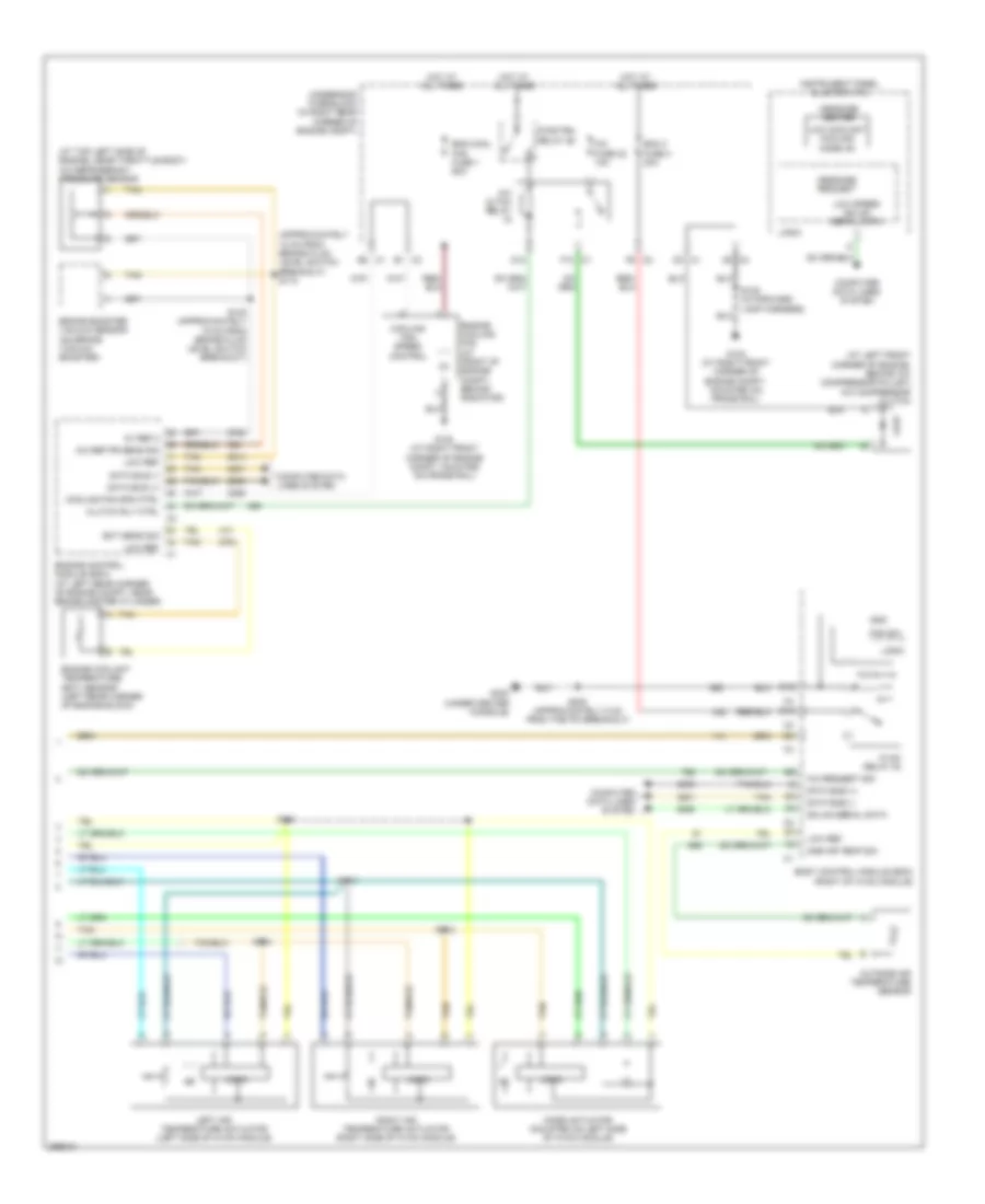
2.0L VIN M Turbo, Manual A/C Wiring Diagram (2 of 2) for Saturn Sky 2007
List of elements for 2.0L VIN M Turbo, Manual A/C Wiring Diagram (2 of 2) for Saturn Sky 2007:
- (approximately 10 cm from brake fluid level switch breakout) s110
- (at left front corner of engine, behind a/c compressor pulley) a/c compressor clutch
- (at top left side of engine, near throttle body) a/c refrigerant pressure sensor
- 5v ref 2
- A/c cltch relay
- A/c fuse 22 10a
- A/c ref pr sens sig
- A/c request sig
- Amb air temp sig
- Bcm 3 fuse 4 30a
- Body control module (bcm) (right of hvac module)
- Brake booster vacuum sensor (on brake vacuum booster)
- C1 b2
- C1 d3
- C1 f10
- C2 f6
- C3 c5
- C3 e1
- Clutch rly ctrl
- Computer data lines system
- Cooling fan spd ctrl
- Cooling fan speed control
- D10
- D12
- Data bus (+)
- Data bus (-)
- E12
- Ect sens sig
- Eng cool fan fuse 1 60a
- Engine control module (ecm) (at left rear corner of engine compt, near brake master cylinder)
- Engine coolant temperature (ect) sensor (left rear corner of engine block)
- Engine cooling fan (at front of engine compt, behind radiator)
- Fan sw
- G102 (at right front corner of engine compt, mounted on frame rail)
- G300 (under center console)
- Gmlan serial data
- Gnd
- Hot at all times
- Hvac relay 30
- Instrument panel cluster (ipc)
- Left air temperature actuator (left side of hvac module)
- Logic
- Low coolant cooling mode on
- Low ref
- Low speed gmlan serial data
- Message center
- Message request
- Mode actuator (mounted on left side of hvac module)
- Outside air temperature sensor
- Pwr/trn relay 26
- Right air temperature actuator (right side of hvac module)
- S102 (approximately 15 cm from brake fluid level switch breakout)
- S105 (in forward lamp harness)
- S111
- S112
- S113
- S114
- S208 (approximately 8 cm from the ipc breakout)
- Tan
- Underhood fuse block (in right rear corner of engine compt)
2.4L VIN B
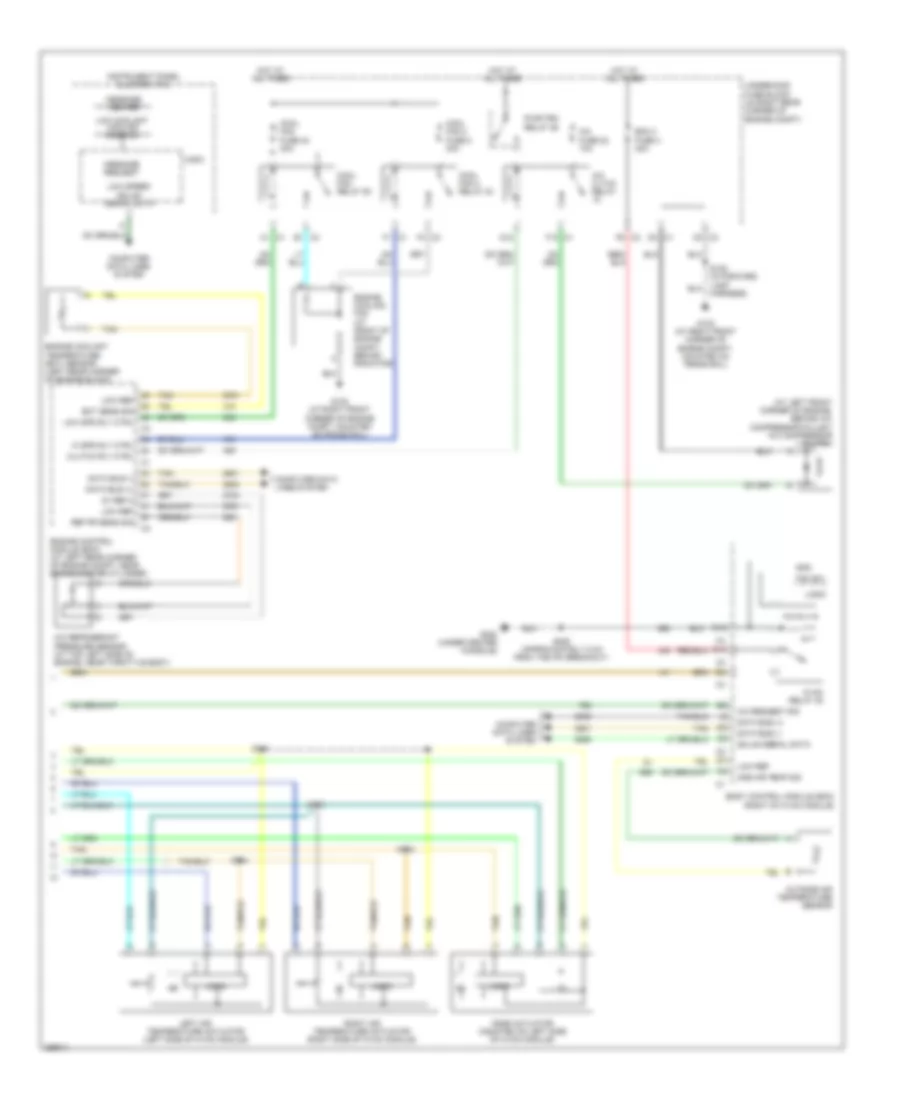
2.4L VIN B, Manual A/C Wiring Diagram (1 of 2) for Saturn Sky 2007
List of elements for 2.4L VIN B, Manual A/C Wiring Diagram (1 of 2) for Saturn Sky 2007:
- (behind right side of dash) blower motor
- (in hvac harness) s225
- 5v ref
- A/c ind
- A/c request sig
- A/c sw sig
- A/c switch
- Air temp door ctrl
- Air temp door pos sig
- Aux air temp door pos sig
- Batt
- Blower motor high speed relay
- Blower motor resistor assembly (below blower motor)
- Blower switch
- Body control module (right of hvac module)
- Defogger system
- Defrost door pos sig
- Evap core temp sens sig
- Evaporator temperature sensor (behind right side of dash)
- G300 (under center console)
- Gnd
- Hot at all times
- Hot in run or start
- Hvac control module (at center of dash, above radio)
- Hvac/ ip ign fuse 16 10a
- Hvac/ pk3 + fuse 10 10a
- Ign1 vol
- Ind ctrl
- Interior lights system
- Logic
- Low ref
- Mode door ctrl
- Mode door pos sig
- Mode sig
- Mode switch
- Off
- Off sig
- Pnk
- Rear defog ind
- Rear defog rly ctrl
- Rear defog sw sig
- Rear defog switch
- Recir door ctrl
- Recir door ctrl b
- Recir door ctrl circuit
- Recir sw sig
- Recirculation actuator (behind right side of dash)
- Recirculation ind
- Recirculation switch
- S203 (in i/p body harness, approximately 10 cm from hvac module breakout)
- S208 (approximately 8 cm from the ipc breakout)
- S226
- S301
- Tan
- Temp ctrl sig
- Temperature control switch
2.4L VIN B, Manual A/C Wiring Diagram (2 of 2) for Saturn Sky 2007
List of elements for 2.4L VIN B, Manual A/C Wiring Diagram (2 of 2) for Saturn Sky 2007:
- (at left front corner of engine, behind a/c compressor pulley) a/c compressor clutch
- 5v ref 2
- A/c cltch relay
- A/c fuse 22 10a
- A/c refrigerant pressure sensor (at top left side of engine, near throttle body)
- A/c request sig
- Amb air temp sig
- Bcm 3 fuse 4 30a
- Body control module (bcm) (right of hvac module)
- C1 a1
- C1 d3
- C1 f1
- C1 f10
- C2 f6
- C3 c5
- C3 e1
- C3 f4
- Clutch rly ctrl
- Computer data lines system
- Cool fan 2 fuse 8 30a
- Cool fan 2 relay 24
- Cool fan fuse 40 30a
- Cool fan relay 50
- D10
- D12
- Data bus (+)
- Data bus (-)
- E12
- Ect sens sig
- Engine control module (ecm) (at left rear corner of engine compt, near brake master cylinder)
- Engine coolant temperature (ect) sensor (left rear corner of engine block)
- Engine cooling fan (at front of engine compt, behind radiator)
- Fan sw
- G102 (at right front corner of engine compt, mounted on frame rail)
- G300 (under center console)
- Gmlan serial data
- Gnd
- Hi spd rly ctrl
- Hot at all times
- Hvac relay 30
- Instrument panel cluster (ipc)
- Left air temperature actuator (left side of hvac module)
- Logic
- Low coolant cooling mode on
- Low ref
- Low spd rly ctrl
- Low speed gmlan serial data
- Message center
- Message request
- Mode actuator (mounted on left side of hvac module)
- Outside air temperature sensor
- Pwr/trn relay 26
- Ref pr sens sig
- Right air temperature actuator (right side of hvac module)
- S105 (in forward lamp harness)
- S111
- S112
- S113
- S114
- S208 (approximately 8 cm from the ipc breakout)
- Tan
- Underhood fuse block (in right rear corner of engine compt)
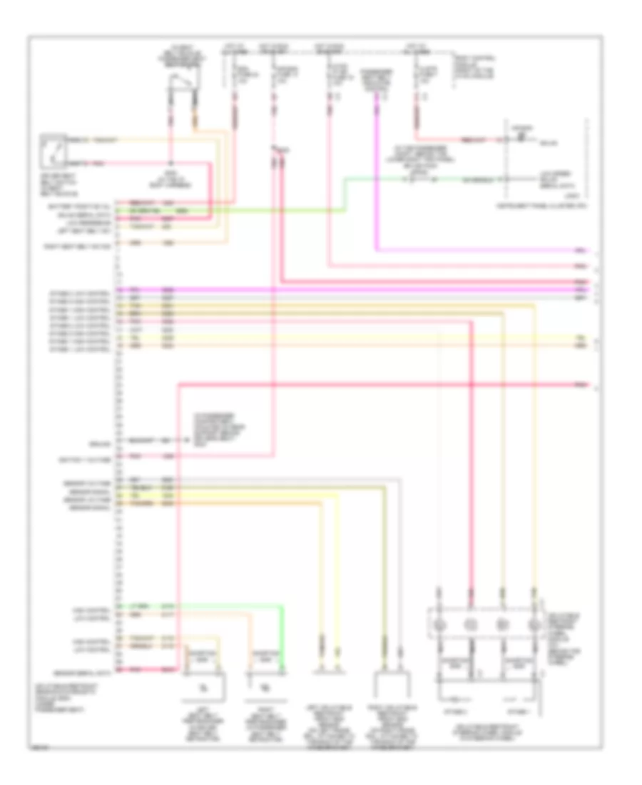
ANTI-LOCK BRAKES
2.0L
2.0L, Anti-lock Brakes Wiring Diagram (1 of 2) for Saturn Sky 2007
List of elements for 2.0L, Anti-lock Brakes Wiring Diagram (1 of 2) for Saturn Sky 2007:
- (at left front corner of engine compt, mounted on frame rail, forward of g101) g105
- (not used)
- 5v ref
- Abs fuse 44 40a
- Abs fuse 57 10a
- Abs fuse 61 20a
- Battery positive voltage
- Brake pressure modulator valve (bpmv)
- Computer data lines system
- Electronic brake control module (ebcm) (at left side of engine compt, mounted on inner frame rail)
- High serial data
- Hot at all times
- Hot in run or start
- Left front inlet solenoid valve
- Left front outlet solenoid valve
- Left rear inlet solenoid valve
- Left rear outlet solenoid valve
- Lf wheel speed sen low ref
- Lf wheel speed sen sig
- Low reference
- Low serial data
- Lr wheel speed sen low ref
- Lr wheel speed sen sig
- Pnk
- Pump motor control
- Rf wheel speed sen low ref
- Rf wheel speed sen sig
- Right front inlet solenoid valve
- Right front outlet solenoid valve
- Right rear inlet solenoid valve
- Right rear outlet solenoid valve
- Rr wheel speed sen low ref
- Rr wheel speed sen sig
- Run/crank ign 1 voltage
- S101
- S109
- Serial data +
- Serial data -
- Sol vlv control
- Tan
- Underhood fuse block (in right rear corner of engine compt)
- W/ active brake control
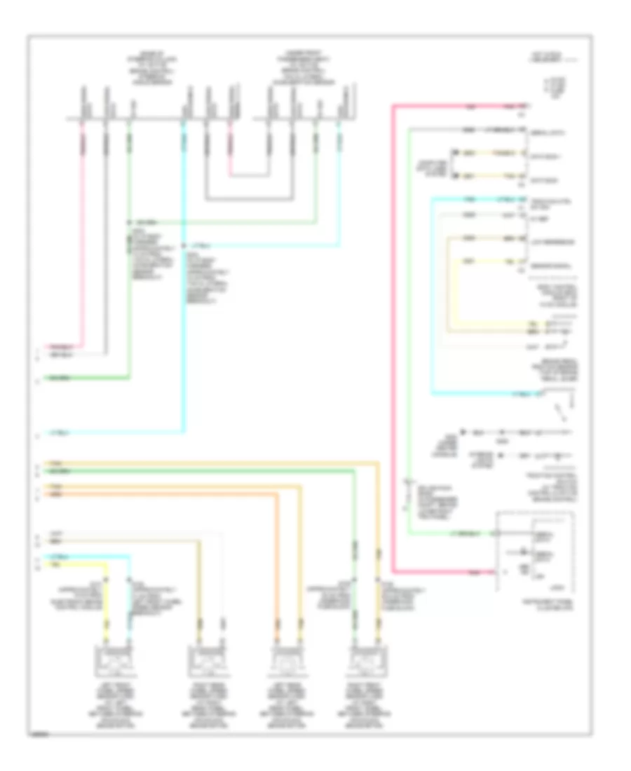
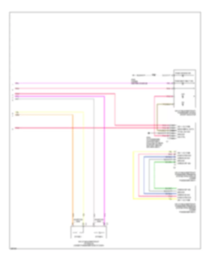
2.0L, Anti-lock Brakes Wiring Diagram (2 of 2) for Saturn Sky 2007
List of elements for 2.0L, Anti-lock Brakes Wiring Diagram (2 of 2) for Saturn Sky 2007:
- (base of steering column) (w/ active brake control) steering angle sensor
- (under front passenger's seat) (w/ active brake control) yaw & lateral acceleration sensor
- 5v ref
- Abs ind
- Body control module (bcm) (right of hvac module)
- Brake pedal position sensor (top of brake pedal lever)
- Computer data lines system
- Data bus +
- Data bus -
- Data high serial
- G300 (under center console)
- Harness, approximately 10 cm from yaw & lateral acceleration sensor breakout)
- High serial data
- Hot in run or start
- Hvac/ ip ign fuse 10a
- Ign
- Instrument panel cluster (ipc)
- Interior lights system
- Left front wheel speed sensor (wss) (at left front wheel, between steering knuckle & brake rotor)
- Left rear wheel speed sensor (wss) (at left rear wheel, between steering knuckle & brake rotor)
- Logic
- Low reference
- Low serial data
- Pnk
- Right front wheel speed sensor (wss) (at right front wheel, between steering knuckle & brake rotor)
- Right rear wheel speed sensor (wss) (at right rear wheel, between steering knuckle & brake rotor)
- S128 (approximately 25.5 cm from underhood fuse block)
- S129 (approximately 28 cm from underhood fuse block)
- S130 (approximately 21 cm from left front wheel speed sensor breakout)
- S131 (approximately 15 cm from electronic brake control module)
- S208
- S304 (in i/p body harness, approximately 18 cm from yaw & lateral acceleration sensor breakout)
- Sensor signal
- Serial data
- Splice pack sp200 (in passenger compt, behind lower right trim panel)
- Tan
- Traction control switch (w/ traction control & active brake control)
- Traction ctrl sw sig
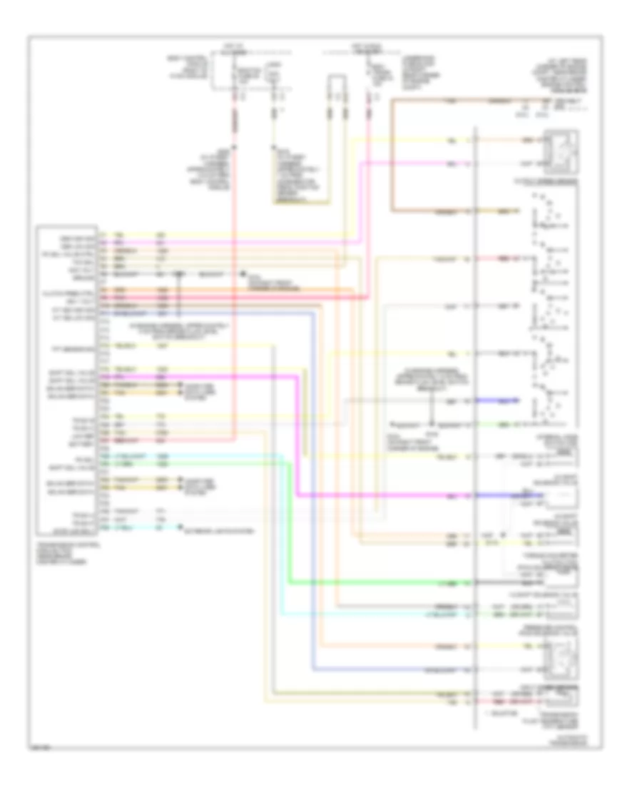
2.4L VIN 5
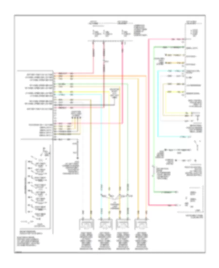
2.4L VIN 5, Anti-lock Brakes Wiring Diagram for Saturn Sky 2007
List of elements for 2.4L VIN 5, Anti-lock Brakes Wiring Diagram for Saturn Sky 2007:
- (in forward lamp harness)
- 5v ref
- Abs fuse 44 30a
- Abs fuse 57 10a
- Abs fuse 61 20a
- Abs ind
- Battery positive voltage
- Body control module (bcm) (right of hvac module)
- Brake pedal position sensor (top of brake pedal lever)
- Brake pressure modulator valve (bpmv)
- Computer data lines system
- Data bus +
- Data bus -
- Electronic brake control module (ebcm) (at left side of engine compartment, mounted on inner frame rail)
- G105 (at left front corner of engine compartment, mounted on frame rail, forward of g101)
- G300 (under center console)
- Hot at all times
- Hot in run or start
- Hvac/ ip ign fuse 10a
- Ign
- Instrument panel cluster (ipc)
- Interior lights system
- Left front inlet
- Left front outlet
- Left front wheel speed sensor (wss) (at left front wheel, between steering knuckle & brake rotor)
- Left rear inlet
- Left rear outlet
- Left rear wheel speed sensor (wss) (at left rear wheel, between steering knuckle & brake rotor)
- Lf wheel speed sen low ref
- Lf wheel speed sen sig
- Logic
- Low reference
- Lr wheel speed sen low ref
- Lr wheel speed sen sig
- Pnk
- Pump motor ctrl
- Rf wheel speed sen low ref
- Rf wheel speed sen sig
- Right front inlet
- Right front outlet
- Right front wheel speed sensor (wss) (at right front wheel, between steering knuckle & brake rotor)
- Right rear inlet
- Right rear outlet
- Right rear wheel speed sensor (wss) (at right rear wheel, between steering knuckle & brake rotor)
- Rr wheel speed sen low ref
- Rr wheel speed sen sig
- Run/crank ign 1 voltage
- S101
- S109
- S128
- S129
- S130
- S131
- S208
- Sensor signal
- Serial data
- Serial data +
- Serial data -
- Sol valve ctrl
- Solenoid valves
- Splice pack sp200 (in passenger compt, behind lower right trim panel)
- Tan
- Traction control switch (w/ traction control & active brake control)
- Traction ctrl sw sig
- Underhood fuse block (in right rear corner of engine compartment)
ANTI-THEFT
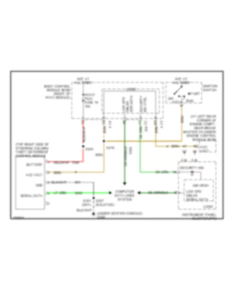
Anti-theft Wiring Diagram for Saturn Sky 2007
List of elements for Anti-theft Wiring Diagram for Saturn Sky 2007:
- (at left rear corner of engine compt, near brake master cylinder) engine control module (ecm)
- (top right side of steering column) theft deterrent control module
- (under center console) g300
- 2.0l
- 2.4l
- Acc
- Acc volt
- Acc volt c1
- Battery
- Body control module (bcm) (right of hvac module)
- Computer data lines system
- Gnd
- Hot at all times
- Hvac/ pk3+ fuse 10 10a
- Ign or b+
- Ignition switch
- Instrument panel cluster (ipc)
- Logic
- Low spd gmlan ser data
- Low spd gmlan serial data
- Off
- Run
- S203
- S207 (solstice)
- S216
- S301 (sky)
- Security ind
- Security ind ctrl
- Serial data
- Start
BODY CONTROL MODULES
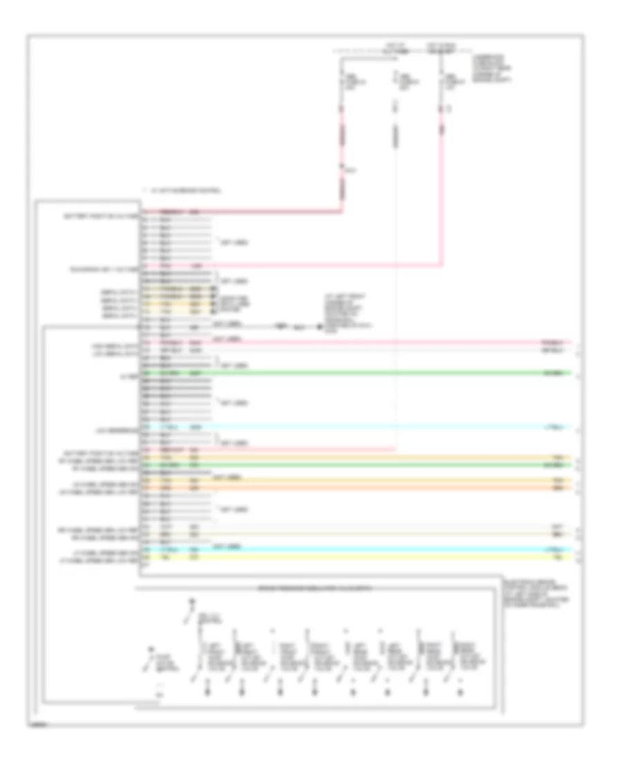
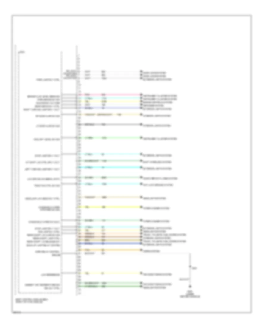
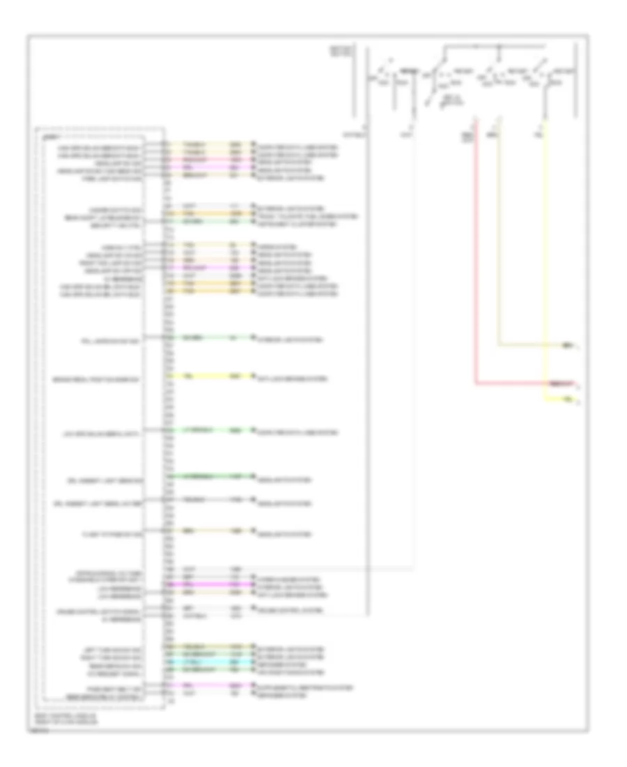
Body Control Modules Wiring Diagram (1 of 4) for Saturn Sky 2007
List of elements for Body Control Modules Wiring Diagram (1 of 4) for Saturn Sky 2007:
- A/t shift lck ctrl sply volt
- Air conditioning system
- Ambient air temperature sig
- Anti-lock brakes system
- Back-up lamp relay control
- Body control module (bcm) (right of hvac module)
- Brake fluid level sens sig
- Computer data lines system
- Coolant level sw sig
- Defogger system
- Door locks system
- Dr lock/
- Drl rly ctrl
- Engine controls system
- Exterior lights system
- Fog lamp rly ctrl
- G300 (under center console)
- Ground
- Headlamp low beam rly ctrl
- Headlights system
- Horn relay control
- Horns system
- Instrument cluster system
- Interior lights system
- Left turn sig lamp sply volt
- Lf door ajar sw sig
- Logic
- Low reference
- Low spd gmlan serial data
- Park brake sw sig
- Park lamp rly ctrl
- Pnk
- Rear compt lamp ctrl
- Rear compt lid ajar sw sig
- Rear compt lid release sw
- Rear defog rly ctrl
- Rf door ajar sw sig
- Right turn sig lamp sply volt
- Run/crank voltage
- S301
- Shift interlock system
- Stop lamp sply volt
- Tan
- Traction ctrl sw sig
- Trunk, tailgate, fuel doors system
- Unlock sig dr lock/ unlock sig
- Windshield wiper mtr park sw sig
- Windshield wiper sw sig 2
- Wiper/washer system
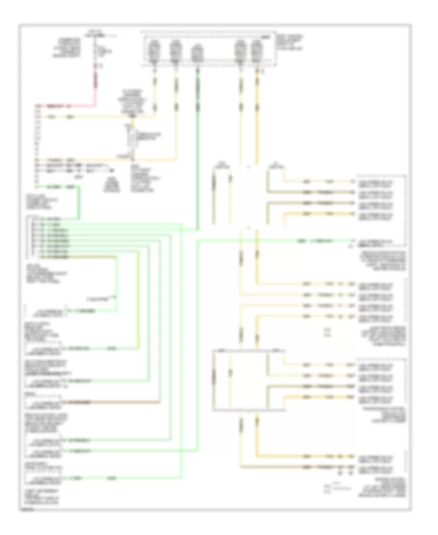
Body Control Modules Wiring Diagram (2 of 4) for Saturn Sky 2007
List of elements for Body Control Modules Wiring Diagram (2 of 4) for Saturn Sky 2007:
- 5v reference
- A/c request signal
- Acc
- Air conditioning system
- Anti-lock brakes system
- Body control module (right of hvac module)
- Brake pedal position snsr sig
- Computer data lines system
- Cruise control switch signal
- Cruise control system
- Defogger system
- Drl ambient light sens low ref
- Drl ambient light sens sig
- Exterior lights system
- Flash to pass sw sig
- Front fog lamp sw sig
- Hazard switch sig
- Headlamp dim sw high beam sig
- Headlamp sw off sig
- Headlamp sw on sig
- Headlamp sw sig
- Headlights system
- High spd gmlan ser data bus +
- High spd gmlan srl data bus -
- Horn rly ctrl
- Horns system
- Ignition switch
- Instrument cluster system
- Interior lights system
- Key in switch
- Left turn sig sw sig
- Logic
- Low reference
- Low spd gmlan serial data
- Off
- Off/run/crank voltage
- Park lamp switch sig
- Pass seat belt ind
- Pnl lamps dim sw sig
- Rear compt lid release sw
- Rear defog relay control
- Rear defog sw sig
- Right turn sig sw sig
- Run
- Security ind ctrl
- Start
- Tan
- Trunk, tailgate, fuel doors system
- Windshield wiper sw sig 1
- Wiper/washer system
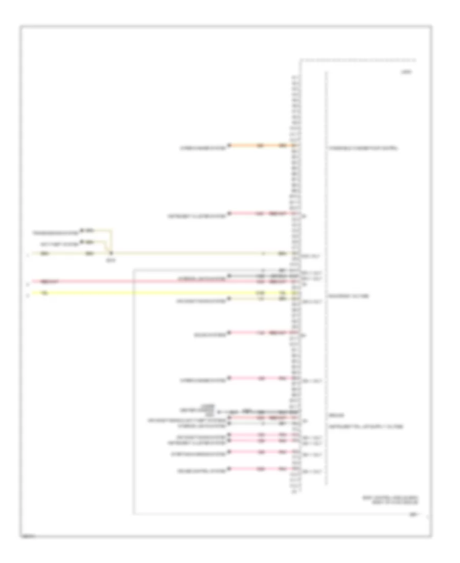
Body Control Modules Wiring Diagram (3 of 4) for Saturn Sky 2007
List of elements for Body Control Modules Wiring Diagram (3 of 4) for Saturn Sky 2007:
- (under center console) g300
- A10
- A11
- A12
- Acc volt
- Air conditioning & anti-theft systems
- Air conditioning system
- Anti-theft system
- B10
- B11
- B12
- Body control module (bcm) (right of hvac module)
- C10
- C11
- C12
- Cruise control system
- D10
- D11
- D12
- E10
- E11
- E12
- F10
- F11
- F12
- Ground
- Ign 1 volt
- Ign 3 volt
- Instrument cluster system
- Interior lights system
- Logic
- Pnk
- Run/crank voltage
- S208
- S216
- Sound systems
- Sply volt
- Starting/charging system
- Transmissions system
- Windshield washer pump control
- Wiper/washer system
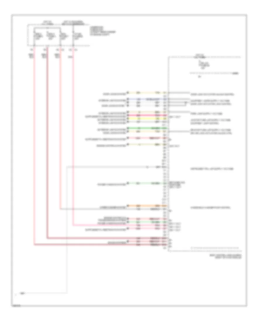
Body Control Modules Wiring Diagram (4 of 4) for Saturn Sky 2007
List of elements for Body Control Modules Wiring Diagram (4 of 4) for Saturn Sky 2007:
- A10
- A11
- A12
- Acc volt
- B10
- B11
- B12
- Bcm 2 fuse 6 40a
- Bcm 3 fuse 4 30a
- Bcm fuse 7 50a
- Body control module (bcm) (right of hvac module)
- C10
- C11
- C12
- Courtesy lamp control
- D10
- D11
- D12
- Door lock actuator lock control
- Door lock actuator unlock control
- Door locks system
- Dr lck fuse 26 15a
- Drv dr lock actuator unlock ctrl
- Engine controls & transmissions systems
- Engine controls system
- Exterior lights system
- Hot at all times
- Hot w/ run/crnk relay 51 energized
- I/p ign fuse 62 20a
- Ign 1 volt
- Interior lights system
- Logic
- Pnk
- Power windows system
- Retained acc pwr fuse sply volt
- Sound systems
- Sply volt
- Tan
- Underhood fuse block (in right rear corner of engine compt)
- Windshield washer pump control
- Wiper/washer system
COMPUTER DATA LINES
Computer Data Lines Wiring Diagram for Saturn Sky 2007
List of elements for Computer Data Lines Wiring Diagram for Saturn Sky 2007:
- (in i/p body harness, approximately 11.5 cm from data link connector) s219
- 2.0l
- 2.4l
- A/t
- Body control module (bcm) (right of hvac module)
- Data link connector (dlc) (under left side of dash)
- Digital radio receiver (in rear compt, behind right side trim panel)
- Dlc fuse 29 15a
- Electronic brake control module (ebcm) (at left side of engine compt, mounted on inner frame rail)
- Engine control module (ecm) (at left rear corner of engine compt, near brake master cylinder)
- F20
- F21
- F32
- F33
- G300 (under center console)
- High speed gmlan serial data bus +
- High speed gmlan serial data bus -
- Hot at all times
- If equipped
- Inflatable restraint sensing & diagnostic module (sdm) (under passenger seat)
- Instrument panel cluster (ipc)
- Logic
- Low speed gm lan serial data
- Low speed gmlan serial data
- M/t
- Radio
- Remote control door lock receiver (rcdlr) (behind driver seat, to right center of rear support)
- S208
- S220 (in i/p body harness, approximately 10 cm from data link connector)
- S301
- Splice pack sp200 (in passenger compt, behind lower right trim panel)
- Tan
- Tan b
- Terminator resistor
- Theft deterrent module (top right side of steering column)
- Transmission control module (tcm) (near brake master cylinder)
- Underhood fuse block (in right rear corner of engine compt)
- Vehicle communication interface module (vcim) (at rear of passenger compt, near back of center console)
- W/ onstar
- W/o onstar
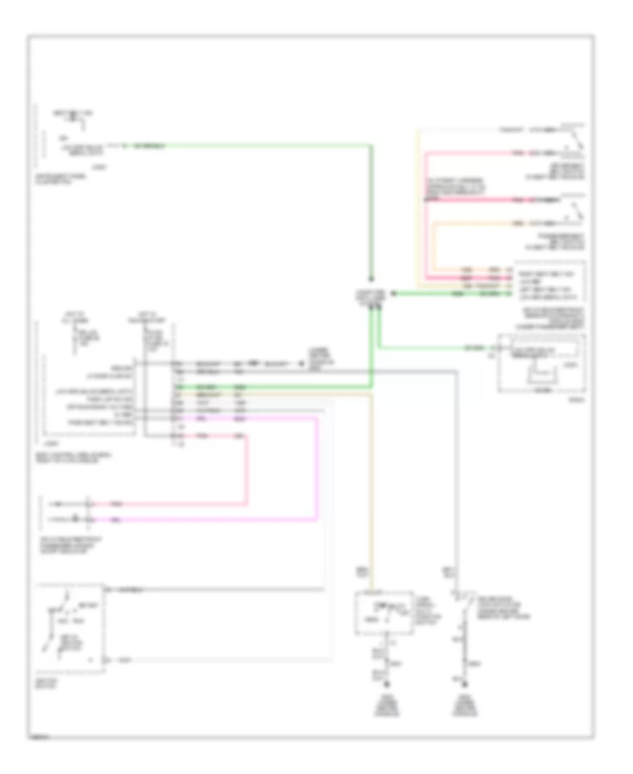
COOLING FAN
2.0L VIN M TURBO
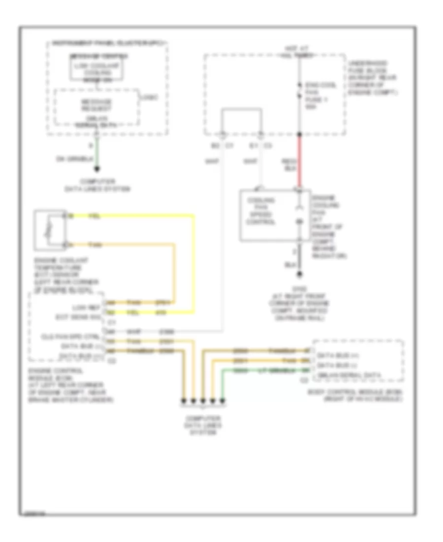
2.0L VIN M Turbo, Cooling Fan Wiring Diagram for Saturn Sky 2007
List of elements for 2.0L VIN M Turbo, Cooling Fan Wiring Diagram for Saturn Sky 2007:
- Body control module (bcm) (right of hvac module)
- C1 b2
- C3 e1
- Clg fan spd ctrl
- Computer data lines system
- Cooling fan speed control
- Data bus (+)
- Data bus (-)
- Ect sens sig
- Eng cool fan fuse 1 60a
- Engine control module (ecm) (at left rear corner of engine compt, near brake master cylinder)
- Engine coolant temperature (ect) sensor (left rear corner of engine block)
- Engine cooling fan (at front of engine compt, behind radiator)
- G102 (at right front corner of engine compt, mounted on frame rail)
- Gmlan serial data
- Hot at all times
- Instrument panel cluster (ipc)
- Logic
- Low coolant cooling mode on
- Low ref
- Message center
- Message request
- Tan
- Underhood fuse block (in right rear corner of engine compt)
2.4L VIN B
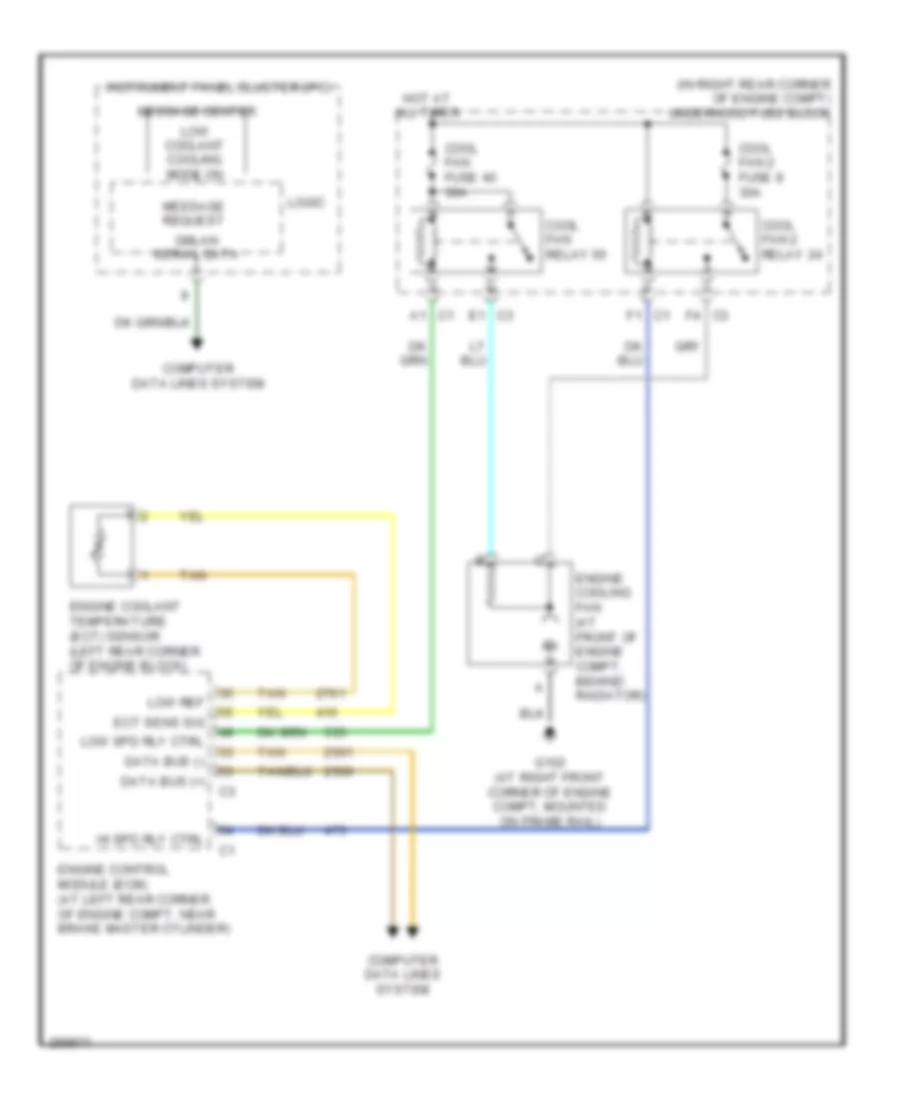
2.4L VIN B, Cooling Fan Wiring Diagram for Saturn Sky 2007
List of elements for 2.4L VIN B, Cooling Fan Wiring Diagram for Saturn Sky 2007:
- (in right rear corner of engine compt) underhood fuse block
- C1 a1
- C1 f1
- C3 e1
- C3 f4
- Computer data lines system
- Cool fan 2 fuse 8 30a
- Cool fan 2 relay 24
- Cool fan fuse 40 30a
- Cool fan relay 50
- Data bus (+)
- Data bus (-)
- Ect sens sig
- Engine control module (ecm) (at left rear corner of engine compt, near brake master cylinder)
- Engine coolant temperature (ect) sensor (left rear corner of engine block)
- Engine cooling fan (at front of engine compt, behind radiator)
- G102 (at right front corner of engine compt, mounted on frame rail)
- Gmlan serial data
- Hi spd rly ctrl
- Hot at all times
- Instrument panel cluster (ipc)
- Logic
- Low coolant cooling mode on
- Low ref
- Low spd rly ctrl
- Message center
- Message request
- Tan
CRUISE CONTROL
2.0L
2.0L, Cruise Control Wiring Diagram for Saturn Sky 2007
List of elements for 2.0L, Cruise Control Wiring Diagram for Saturn Sky 2007:
- (on right front corner of engine) g104
- 5v ref
- 5v ref 2
- 5v ref 3
- Accelerator pedal position (app) sensor (top of accelerator pedal bracket)
- App snsr 1 sig
- App snsr 2 sig
- B10 c2
- Body control module (bcm) (right of hvac module) logic
- Bpp sens sig
- Brake pedal position sensor (top of brake pedal lever)
- C1 d
- C2 d
- Clutch pedal position (cpp) switch (m/t) (mounted at top of clutch pedal bracket)
- Computer data lines system
- Cpp sw sig
- Cruise control sw sig
- Cruise on/off switch
- Emissions fuse 10a
- Engine control module (ecm) (at left rear corner of engine compt, near brake master cylinder)
- F9 c4
- G304 (in passenger compartment, mounted on rear support behind driver seat)
- Gnd
- Hot at all times
- Hot in acc or run
- Inflatable restraint steering wheel module coil
- Left steering wheel controls switch
- Loe ref
- Low ref
- Pnk
- Rest +
- S108
- S201
- Serial data bus +
- Serial data bus -
- Set -
- Tac mtr ctrl 1
- Tac mtr ctrl 2
- Tan
- Throttle body
- Tp sen sig 2
- Tp sens 2 sig
- Underhood fuse block (in right rear corner of engine compt)
- Vehicle speed sensor (vss) (m/t) (on side of manual transmission)
- Vss high sig
- Vss low sig
2.4L VIN 5
2.4L VIN 5, Cruise Control Wiring Diagram for Saturn Sky 2007
List of elements for 2.4L VIN 5, Cruise Control Wiring Diagram for Saturn Sky 2007:
- (on right front corner of engine) g104
- 5v ref
- 5v ref 1
- 5v ref 2
- Accelerator pedal position (app) sensor (top of accelerator pedal bracket)
- App snsr 1 sig
- App snsr 2 sig
- Body control module (bcm) (right of hvac module) logic
- Bpp sens sig
- Brake pedal position sensor (top of brake pedal lever)
- C1 d
- C2 b10
- C2 d
- C4 f9
- Clutch pedal position (cpp) switch (m/t) (mounted at top of clutch pedal bracket)
- Computer data lines system
- Cpp sw sig
- Cruise control sw sig
- Cruise on/off switch
- Emissions fuse 10a
- Engine control module (ecm) (at left rear corner of engine compt, near brake master cylinder)
- Eps/str whl cntrl fuse 2a
- G304 (in passenger compartment, mounted on rear support behind driver seat)
- Gnd
- Hot at all times
- Hot in acc or run
- Inflatable restraint steering wheel module coil
- Left steering wheel controls switch
- Low ref
- Pnk
- Rest +
- S108
- S201
- Serial data bus +
- Serial data bus -
- Set -
- Tac mtr ctrl 1
- Tac mtr ctrl 2
- Tan
- Throttle body
- Tp sens 1 sig
- Tp sens 2 sig
- Underhood fuse block (in right rear corner of engine compt)
- Vehicle speed sensor (vss) (m/t) (on side of manual transmission)
- Vss high sig
- Vss low sig
DEFOGGERS
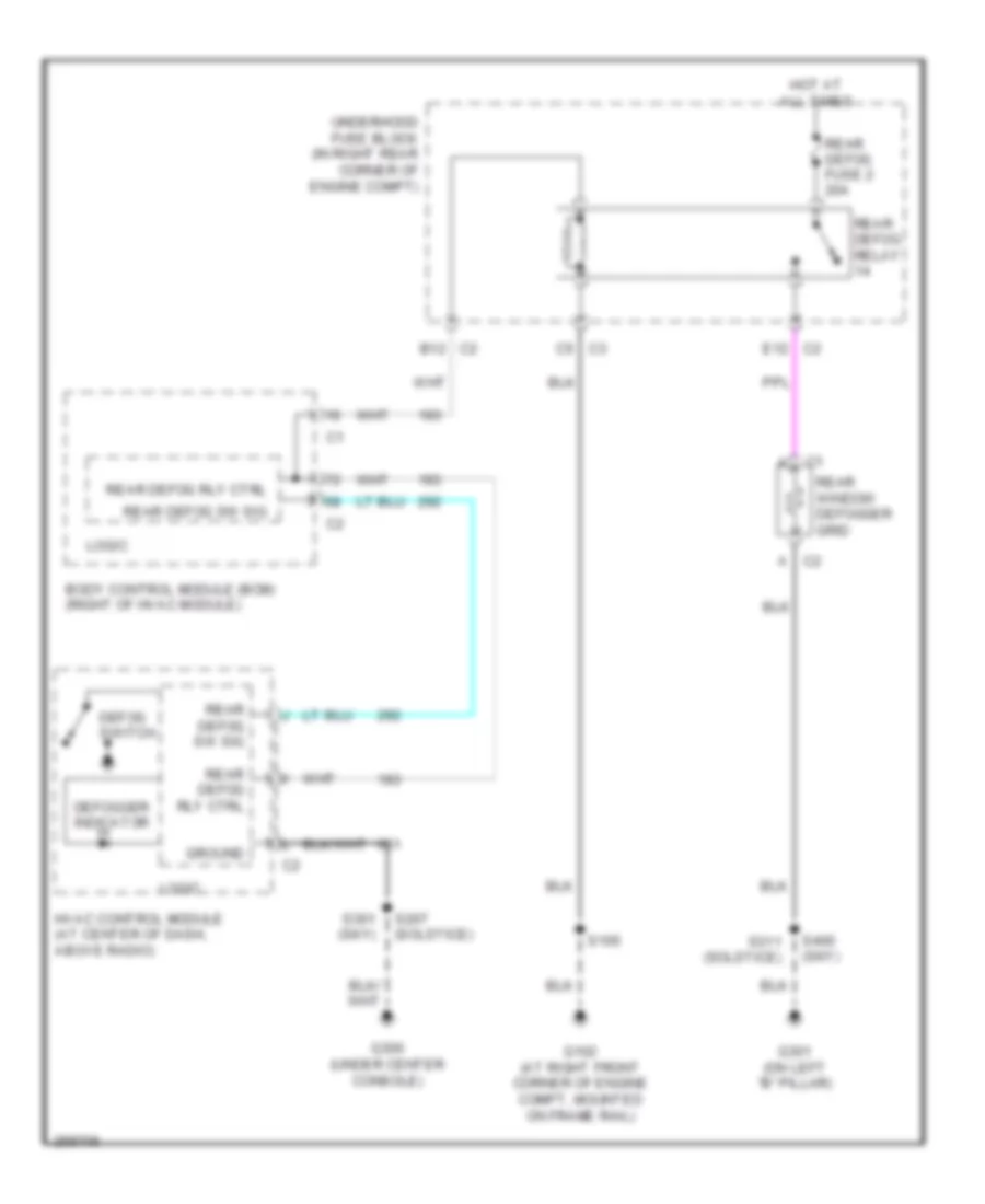
Defoggers Wiring Diagram for Saturn Sky 2007
List of elements for Defoggers Wiring Diagram for Saturn Sky 2007:
- Body control module (bcm) (right of hvac module)
- C2 a
- C2 b12
- C2 e12
- C3 c5
- Defog switch
- Defogger indicator
- G102 (at right front corner of engine compt, mounted on frame rail)
- G300 (under center console)
- G301 (on left "b" pillar)
- Ground
- Hot at all times
- Hvac control module (at center of dash, above radio)
- Logic
- Rear defog fuse 2 20a
- Rear defog relay
- Rear defog rly ctrl
- Rear defog sw sig
- Rear window defogger grid
- S105
- S207 (solstice)
- S301 (sky)
- S311 (solstice)
- S400 (sky)
- Underhood fuse block (in right rear corner of engine compt)
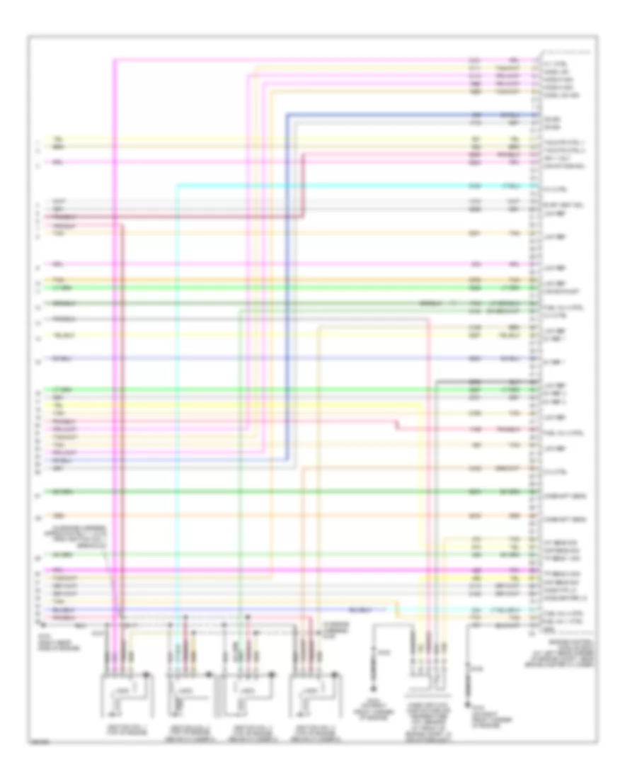
ENGINE PERFORMANCE
2.0L VIN M
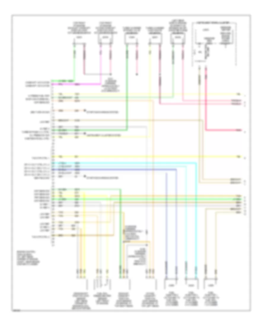
2.0L VIN M, Engine Performance Wiring Diagram (1 of 4) for Saturn Sky 2007
List of elements for 2.0L VIN M, Engine Performance Wiring Diagram (1 of 4) for Saturn Sky 2007:
- (in engine harness, approximately 5 cm from tan ignition coil 4 breakout) s140
- (left rear side of engine) evaporative emission (evap) canister purge solenoid
- (top front of engine) exhaust camshaft position (cmp) actuator solenoid
- (top front of engine) intake camshaft position (cmp) actuator solenoid
- 5v ref 1
- 5v ref 2
- 5v ref 3
- Camshaft actuator
- Ckp sens sig
- Cmp sens sig
- Crankshaft position (ckp) sensor (left rear corner of engine block, above starter)
- Dfi hi volt ctrl cyl 2
- Dfi hi volt ctrl cyl 4
- Dfi hi volt sply cyl 2
- Dfi hi volt sply cyl 4
- Engine control module (ecm) (at left rear corner of engine compt, near brake master cylinder)
- Evap can purge sol
- Exhaust camshaft position (cmp) sensor (on engine, at top right rear)
- Frp sens sig
- Fuel injector 1 (attached to fuel rail at number 1 cylinder)
- Fuel injector 2 (attached to fuel rail at number 2 cylinder)
- Fuel injector 4 (attached to fuel rail at number 4 cylinder)
- Fuel rail pressure (frp) sensor (left front of engine)
- Gen field sig
- Gen turn on sig
- Hi press fuel pmp
- Ign
- Instrument cluster system
- Instrument panel cluster
- Intake camshaft position (cmp) sensor (on engine, at top left rear)
- Logic
- Low ref
- Malfunction ind lamp
- Map sens sig
- Message center
- Message req (ecm)
- Oil press sw sig
- Pnk
- Reduced engine power check gas cap
- S121 (in engine harness, approximately 4.5 cm from g104 breakout)
- S126 (in engine harness, approximately 4.5 cm from g104 breakout)
- Starting/charging system
- Tac mtr ctrl 1
- Tac mtr ctrl 2
- Tan
- Turbo bypass vlv ctrl
- Turbo charged wastagate solenoid
- Turbo charger bypass valve solenoid
- Wastegate sol ctrl
2.0L VIN M, Engine Performance Wiring Diagram (2 of 4) for Saturn Sky 2007
List of elements for 2.0L VIN M, Engine Performance Wiring Diagram (2 of 4) for Saturn Sky 2007:
- (in exhaust pipe, upstream of catalytic converter) heated oxygen sensor (ho2s) 1
- (left front
- (left rear
- (lower left front of engine) knock sensor (ks) 1
- (lower left side of engine, above starter motor) knock sensor (ks) 2
- (on left side
- (top left rear of engine) high pressure fuel pump
- 5v ref 1
- A tan
- Absolute pressure (map) sensor
- Corner of engine block) engine coolant
- Dfi hi volt ctrl cyl 1
- Dfi hi volt ctrl cyl 3
- Dfi hi volt sply cyl 1
- Ect sens sig
- Engine control module (ecm) (at left rear corner of engine compt, near brake master cylinder)
- Fuel injector 3 (attached to fuel rail at number 3 cylinder)
- Hi press fuel pmp
- Ho2s hi sig sens 1
- Ho2s htr low sens 1
- Ho2s input pmp current
- Ho2s low sig sens 1
- Ho2s pmp current sens 1
- Ic 1 ctrl
- Ic 2 ctrl
- Ic 3 ctrl
- Ic 4 ctrl
- Ks 1 sig
- Ks 2 sig
- Low ref
- Mil ctrl
- Nca
- Of engine) intake air
- Of engine, near throttle body) manifold
- Pnk
- Pressure & temperature sensor
- S141 (in engine harness, approximately 15 cm from windshield washer fluid pump)
- S142 (in engine harness, approximately 7 cm from map sensor breakout)
- Tan
- Temperature (ect) sensor
- Tmap air press sig
- Tmap temp sig
- Tp sens 1 sig
- Tp sens 2 sig
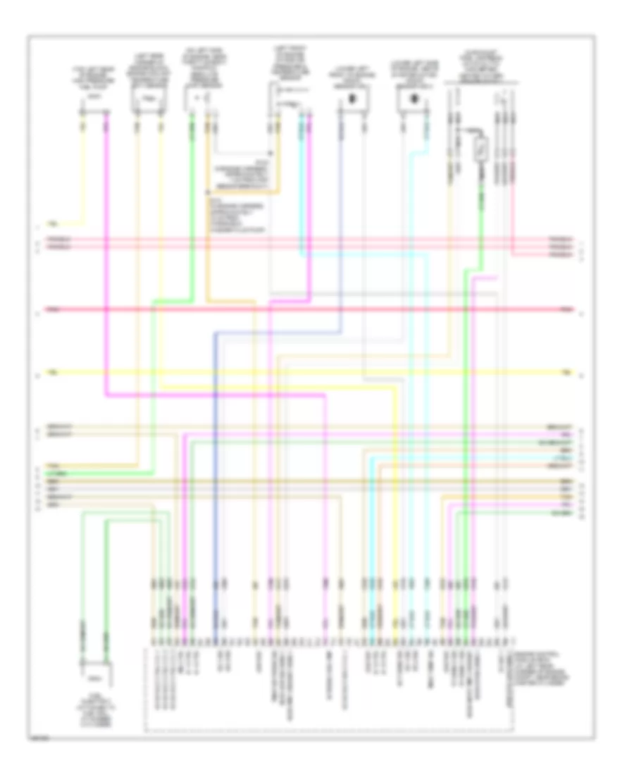
2.0L VIN M, Engine Performance Wiring Diagram (3 of 4) for Saturn Sky 2007
List of elements for 2.0L VIN M, Engine Performance Wiring Diagram (3 of 4) for Saturn Sky 2007:
- (at right front corner of engine compt, mounted on frame rail) g102
- (in engine harness, approximately 11.5 cm from ignition coil 1 breakout) s117
- (in engine harness, approximately 3 cm from ignition coil 3 breakout) s123
- A11
- B10
- B12
- C12
- Can vent fuse 64 10a
- Ecm fuse 42 20a
- Ecm/trans fuse 43 15a
- Emissions fuse 33 10a
- F12
- Fuel pump fuse 13 15a
- Fuel pump relay 19
- G101 (at left front corner of engine compt, mounted on frame rail)
- G103 (right rear side of engine)
- Heated oxygen sensor (ho2s) 2 (in exhaust pipe, downstream of catalytic converter)
- Hot at all times
- Hot in run or start
- I/p ign fuse 62 20a
- Ignition coil 1 (top of engine, above cylinder 1)
- Ignition coil 2 (top of engine, above cylinder 2)
- Ignition coil 3 (top of engine, above cylinder 3)
- Ignition coil 4 (top of engine, above cylinder 4)
- Inj/ ign mdl fuse 45 15a
- Logic
- Nca
- Pnk
- Pwr/trn relay 26
- Run/crnk relay 51
- S103
- S105
- S107
- S124 (in engine harness, approximately 3 cm from ignition coil 3 breakout)
- S201 (m/t)
- Tan
- Throttle body
- Turbo fuse 41 10a
- Underhood fuse block (in right rear corner of engine compt)
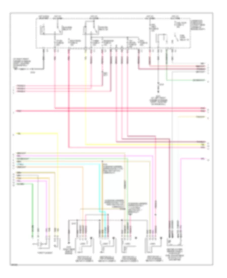
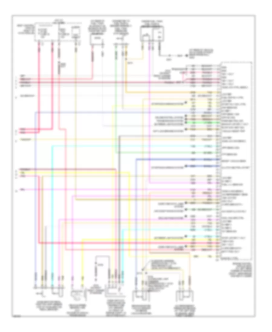
2.0L VIN M, Engine Performance Wiring Diagram (4 of 4) for Saturn Sky 2007
List of elements for 2.0L VIN M, Engine Performance Wiring Diagram (4 of 4) for Saturn Sky 2007:
- (a/t)
- (at rear of fuel tank) evaporative emission (evap) canister vent solenoid
- (at rear of vehicle, on outside of right rear frame rail) g402
- (connected to fuel pump & sender assembly) fuel tank pressure (ftp) sensor
- (in engine harness, approximately 10 cm from brake fluid level switch breakout)
- (inside fuel tank) fuel pump & sender assembly
- 5v ref 1
- 5v ref 2
- 5v ref 3
- A/c comp clutch rly
- A/c refrgerent sens
- A/c refrigerant pressure sensor (at top left side of engine, near throttle body)
- Acc volt
- Accelerator pedal position (app) sensor (top of accelerator pedal bracket)
- Air conditioning system
- Anti-lock brakes system
- App sens 1 sig
- App sens 2 sig
- Backup lmp sply volt
- Batt pos volt
- Body control module (right of hvac module)
- Boost vacuum sens
- Brake booster vacuum sensor (on brake vacuum booster)
- Clutch neutral start
- Computer data lines system
- Cool fan spd ctrl
- Cooling fans system
- Cpp sw sig
- Cruise control system
- Ecm/ tcm fuse 25 10a
- Engine control module (ecm) (at left rear corner of engine compt, near brake master cylinder)
- Evap can vent sol
- Exterior lights system
- Ftp sens sig
- Fuel lvl sens sig
- Fuel pmp rly ctrl
- G104 (on right front corner of engine)
- Gnd
- Hi spd ser data +
- Hi spd ser data -
- Ho2s hi sig sens 2
- Ho2s low ctrl sens 2
- Ho2s low sig sens 2
- Hot at all times
- Hvac/ ip ign fuse 16 10a
- Iat sens sig
- Ign 1 volt
- Level switch breakout)
- Logic
- Low ref
- Maf sens sig
- Main rly ctrl
- Mass air flow (maf)/intake air temperature (iat) sensor (at front of engine compt, in air intake duct)
- Park/neutral sig
- Pnk
- S108
- S110
- S137
- S401
- S410
- Start rly coil ctrl
- Starting/charging system
- Stop lmp sply volt
- Tan
- Transmissions system
- Vacuum assist pmp
- Vehicle speed sensor (vss) (m/t) (on side of manual transmission)
- Vss hi sig
- Vss low sig
2.4L VIN B
2.4L VIN B, Engine Performance Wiring Diagram (1 of 4) for Saturn Sky 2007
List of elements for 2.4L VIN B, Engine Performance Wiring Diagram (1 of 4) for Saturn Sky 2007:
- 5v ref 1
- 5v ref 2
- A/c clutch rly
- Acc volt
- Accelerator pedal position (app) sensor (top of accelerator pedal bracket)
- Air conditioning system
- App sen 1 sig
- App sens 2 sig
- Batt
- Body control module (right of hvac module)
- Cool fan rly ctrl
- Cooling fans system
- Ecm/ tcm fuse 25 10a
- Engine control module (ecm) (at left rear corner of engine compt, near brake master cylinder)
- Evap sol ctrl
- Exterior lights system
- Ftp sens sig
- Fuel lvl sens sig
- Fuel pmp rly ctrl
- Fuel pump & sender assembly (inside fuel tank)
- Fuel pump fuse 13 15a
- Fuel pump relay 19
- Fuel tank pressure (ftp) sensor (connected to fuel pump & sender assembly)
- G102 (at left front corner of engine compt, mounted on frame rail)
- G402 (at rear of vehicle, on outside of right rear frame rail)
- Hot at all times
- Hvac/ ip ign fuse 16 10a
- Ign
- Ign 1 volt
- Instrument panel cluster
- Logic
- Low ref
- Main rly ctrl
- Malfunction ind lamp
- Message center
- Message req (ecm)
- Mil ctrl
- Pnk
- Reduced engine power check gas cap
- S105
- S206 (a/t)
- S401
- S410
- Start rly coil
- Starting/charging system
- Stop lmp sply
- Tan
- Underhood fuse block (in right rear corner of engine compt)
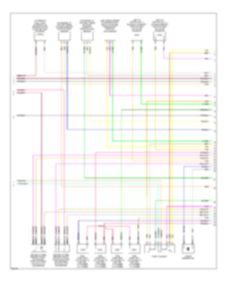
2.4L VIN B, Engine Performance Wiring Diagram (2 of 4) for Saturn Sky 2007
List of elements for 2.4L VIN B, Engine Performance Wiring Diagram (2 of 4) for Saturn Sky 2007:
- (at right front corner of engine compt, mounted on frame rail) g102
- (pins 68 to 73 not used)
- 5v ref 2
- A/c pres sig
- A11
- Air conditioning system
- B10
- C12
- Can vent fuse 64 10a
- Cluster system instrument
- Computer data lines system
- Cool fan rly
- Cooling fans system
- Ecm fuse 42 15a
- Ecm/trans fuse 43 15a
- Ect sens sig
- Emissions fuse 33 10a
- Engine control module (ecm) (at left rear corner of engine compt, near brake master cylinder)
- Engine coolant temperature (ect) sensor (left rear corner of engine block)
- Evaporative emission (evap) canister purge solenoid (at top left rear corner of engine)
- F12
- Gen field sig
- Gen turn sig
- Hot at all times
- Hot in run or start
- I/p ign fuse 62 20a
- Inj ign mdl fuse 45 10a
- Low ref
- Manifold absolute pressure (map) sensor (on left side of engine, near throttle body)
- Map sens sig
- Oil pres sig
- Park/neutral
- Pnk
- Pnp sw sig
- Pwr/trn relay 26
- Run/crnk relay 51
- S105
- S135 (m/t)
- Ser data+
- Ser data-
- Starting/ charging system
- Starting/charging system
- Tan
- Transmissions system
- Underhood fuse block (in right rear corner of engine compt)
- Vehicle speed sensor (m/t) (on side of manual transmission)
- Vss hi sig
- Vss low sig
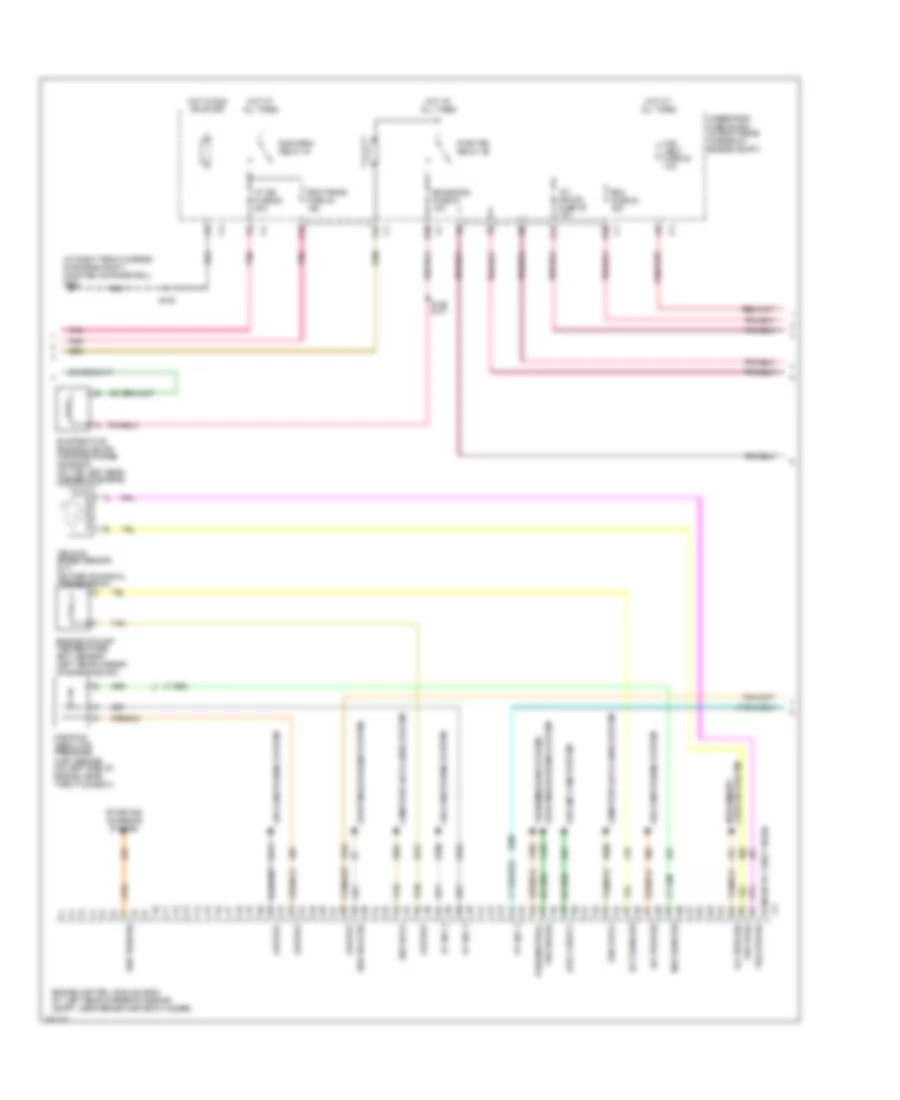
2.4L VIN B, Engine Performance Wiring Diagram (3 of 4) for Saturn Sky 2007
List of elements for 2.4L VIN B, Engine Performance Wiring Diagram (3 of 4) for Saturn Sky 2007:
- (at rear of fuel tank) evaporative emission (evap) canister vent solenoid
- (left of ignition coil 1) exhaust camshaft position (cmp) actuator solenoid
- (left of ignition coil 1) intake camshaft position (cmp) actuator solenoid
- (left rear corner of engine block, below starter) crankshaft position (ckp) sensor
- (on engine, at top left rear) intake camshaft position (cmp) sensor
- (on engine, at top right rear) exhaust camshaft position (cmp) sensor
- Fuel injector 1 (attached to fuel rail at number 1 cylinder)
- Fuel injector 2 (attached to fuel rail at number 2 cylinder)
- Fuel injector 3 (attached to fuel rail at number 3 cylinder)
- Fuel injector 4 (attached to fuel rail at number 4 cylinder)
- Heated oxygen sensor (ho2s) 1 (in exhaust pipe, upstream of catalytic converter)
- Heated oxygen sensor (ho2s) 2 (in exhaust pipe, downstream of catalytic converter)
- Knock sensor (ks)
- Nca
- Pnk
- S119
- Tan
- Throttle body
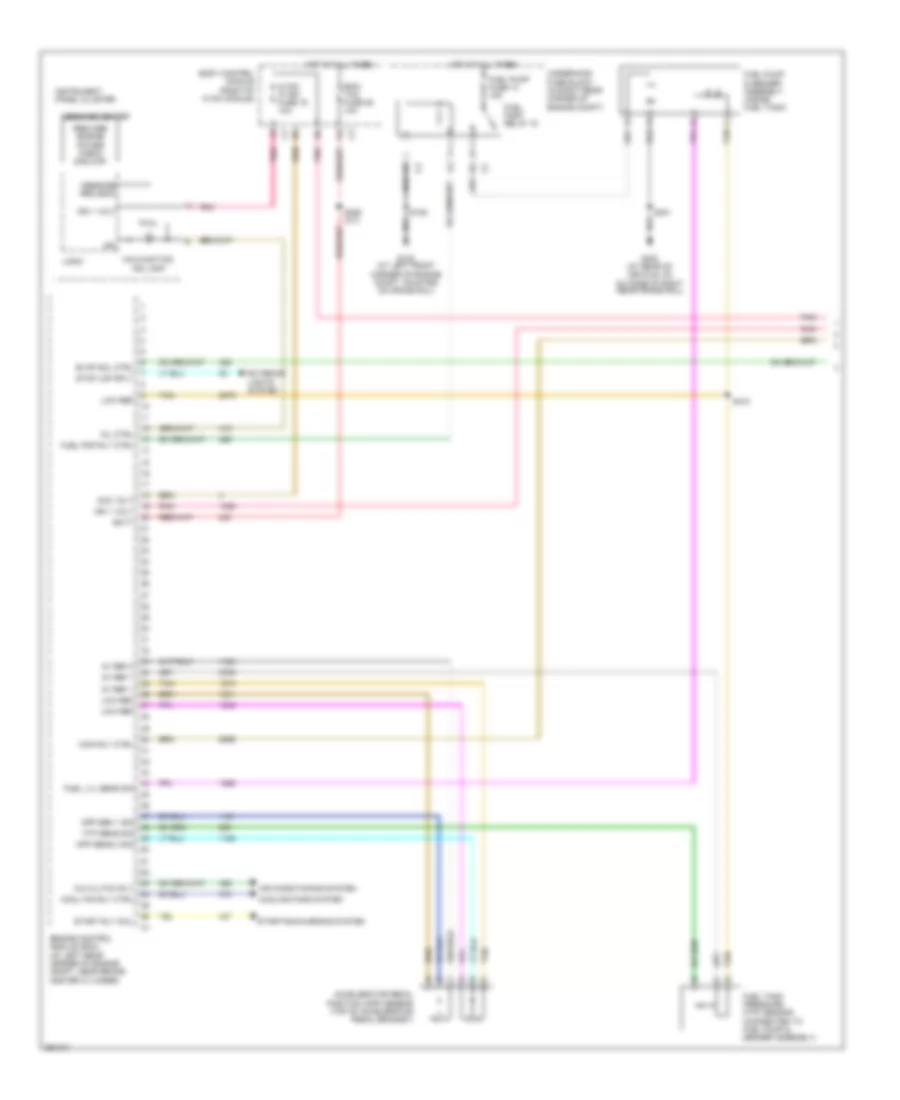
2.4L VIN B, Engine Performance Wiring Diagram (4 of 4) for Saturn Sky 2007
List of elements for 2.4L VIN B, Engine Performance Wiring Diagram (4 of 4) for Saturn Sky 2007:
- (in engine harness) s106
- (in engine harness, approximately 11.5 cm from ignition coil 1 breakout)
- 5v ref 1
- 5v ref 2
- Cam exhaust
- Cam intake sol
- Camshaft sens
- Ckp sens sig
- Engine control module (ecm) (at left rear corner of engine compt, near brake master cylinder)
- Evap vent sol
- Fuel inj 1 ctrl
- Fuel inj 2 ctrl
- Fuel inj 3 ctrl
- Fuel inj 4 ctrl
- G103 (right rear side of engine)
- G104 (on right front corner of engine)
- Gnd
- Ho2s heater lo
- Ho2s hi sig
- Ho2s htr lo
- Ho2s low
- Ho2s low sig
- Iat sens sig
- Ic 1 ctrl
- Ic 2 ctrl
- Ic 3 ctrl
- Ic 4 ctrl
- Ign 1 volt
- Ignition coil 1 (top of engine,
- Ignition coil 2 (top of engine, above cylinder 2)
- Ignition coil 3 (top of engine, above cylinder 3)
- Ignition coil 4 (top of engine, above cylinder 4)
- Ks sig
- Logic
- Low ref
- Maf sens sig
- Mass air flow (maf)/intake air temperature (iat) sensor (at front of engine compt, in air intake duct)
- S107
- S108
- S117
- Tac mtr ctrl 1
- Tac mtr ctrl 2
- Tan
- Tp sens 1 sig
- Tp sens 2 sig
EXTERIOR LIGHTS
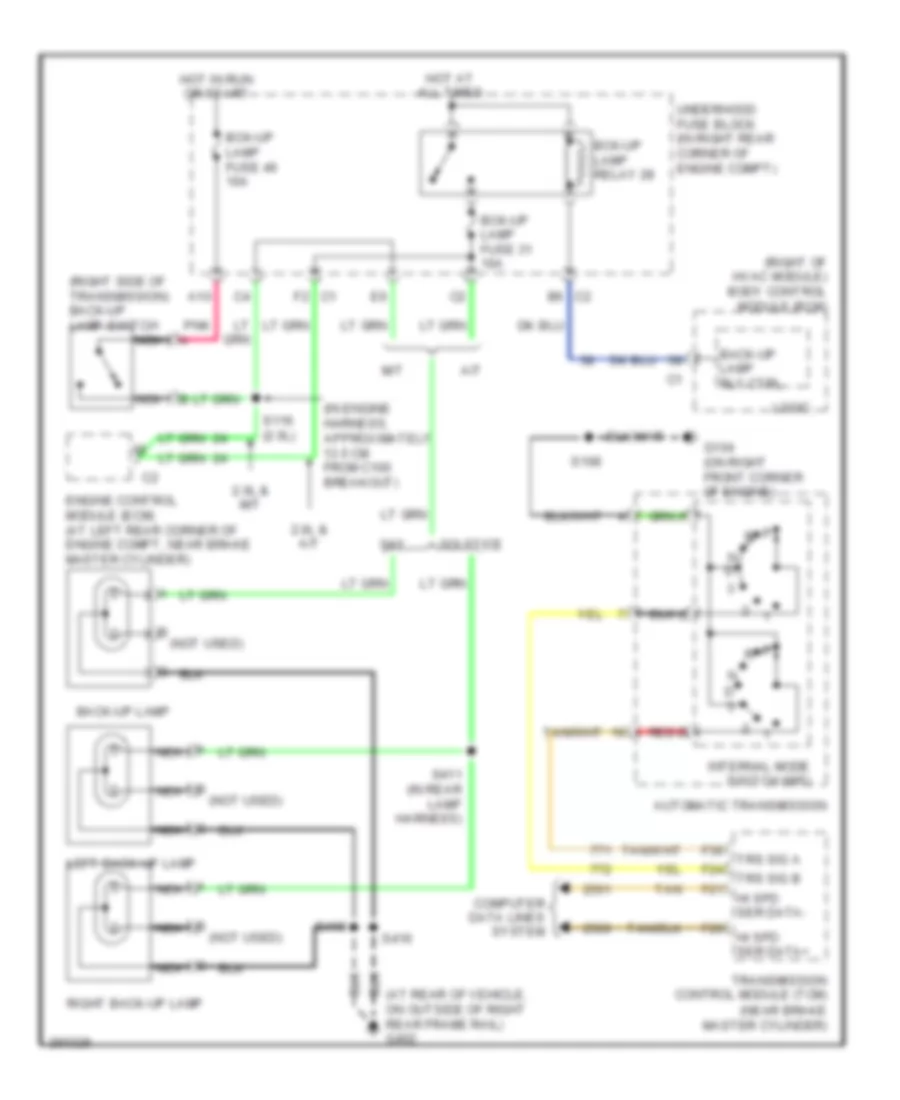
Back-up Lamps Wiring Diagram for Saturn Sky 2007
List of elements for Back-up Lamps Wiring Diagram for Saturn Sky 2007:
- (at rear of vehicle, on outside of right rear frame rail) g402
- (in engine harness, approximately 13.5 cm from c100 breakout)
- (near brake master cylinder)
- (not used)
- (right of hvac module) body control module (bcm)
- (right side of transmission) back-up lamp switch
- 2.0l & a/t
- 2.0l & m/t
- A/t
- A10
- Automatic transmission
- B (not used)
- B6 c2
- Back-up lamp
- Back-up lamp rly ctrl
- Bck-up lamp fuse 31 10a
- Bck-up lamp fuse 46 10a
- Bck-up lamp relay 28
- Computer data lines system
- Engine control module (ecm) (at left rear corner of engine compt, near brake master cylinder)
- F2 c1
- F20
- F21
- F24
- F36
- G104 (on right front corner of engine)
- Hi spd ser data+
- Hi spd ser data-
- Hot at all times
- Hot in run or start
- Internal mode switch (ims)
- Left back-up lamp
- Logic
- M/t
- N d
- Nca
- Pnk
- Red d
- Right back-up lamp
- S108
- S116 (2.0l)
- S410
- S411 (in rear lamp harness)
- S416
- Sky
- Solstice
- Tan
- Transmission control module (tcm)
- Trs sig a
- Trs sig b
- Underhood fuse block (in right rear corner of engine compt)
Exterior Lamps Wiring Diagram for Saturn Sky 2007
List of elements for Exterior Lamps Wiring Diagram for Saturn Sky 2007:
- (at left front corner of engine compt, mounted on frame rail) g101
- (at right front corner of engine compt, mounted on frame rail) g102
- 5v ref
- A12
- Auto
- Body control module (bcm) (right of hvac module)
- Brake pedal position sensor (top of brake pedal lever)
- Brake sens sig
- Center high mounted stop lamp (chmsl)
- Engine controls & transmissions systems
- G300 (under center console)
- G400 (at rear of vehicle, on right rear frame rail, above right rear wheel)
- G402 (at rear of vehicle, on outside of right rear frame rail)
- Grd
- Ground distribution system
- Hazard sw sig
- Hazard switch
- Head
- Hot at all times
- Interior lights system
- L turn sig sw sig
- Left front marker lamp
- Left front park lamp
- Left front park/ turn lamp
- Left inner tail/ stop & turn signal lamp
- Left outer tail/ stop & turn signal lamp
- Left rear marker lamp
- License lamp
- Logic
- Low ref
- Lr sply volt
- Major
- Minor
- Nca
- Off
- Park
- Park lamp rly ctrl
- Prk lamps fuse 69 15a
- Prk lamps relay 68
- R turn sig sw sig
- Right front marker lamp
- Right front park lamp
- Right front park/ turn lamp
- Right inner tail/ stop & turn signal lamp
- Right outer tail/ stop & turn signal lamp
- Right rear marker lamp
- Rr sply volt
- S103
- S105
- S134 (in i/p body harness, approximately 29.5 cm from the underhood fuse block breakout)
- S200
- S208
- S301
- S402
- S405
- S406
- S407
- S408
- S409
- S416
- S420
- Sply volt
- Stop lamp sply volt
- Stop lamp sw sig
- Turn signal/ multi-function switch
- Underhood fuse block (in right rear corner of engine compt)
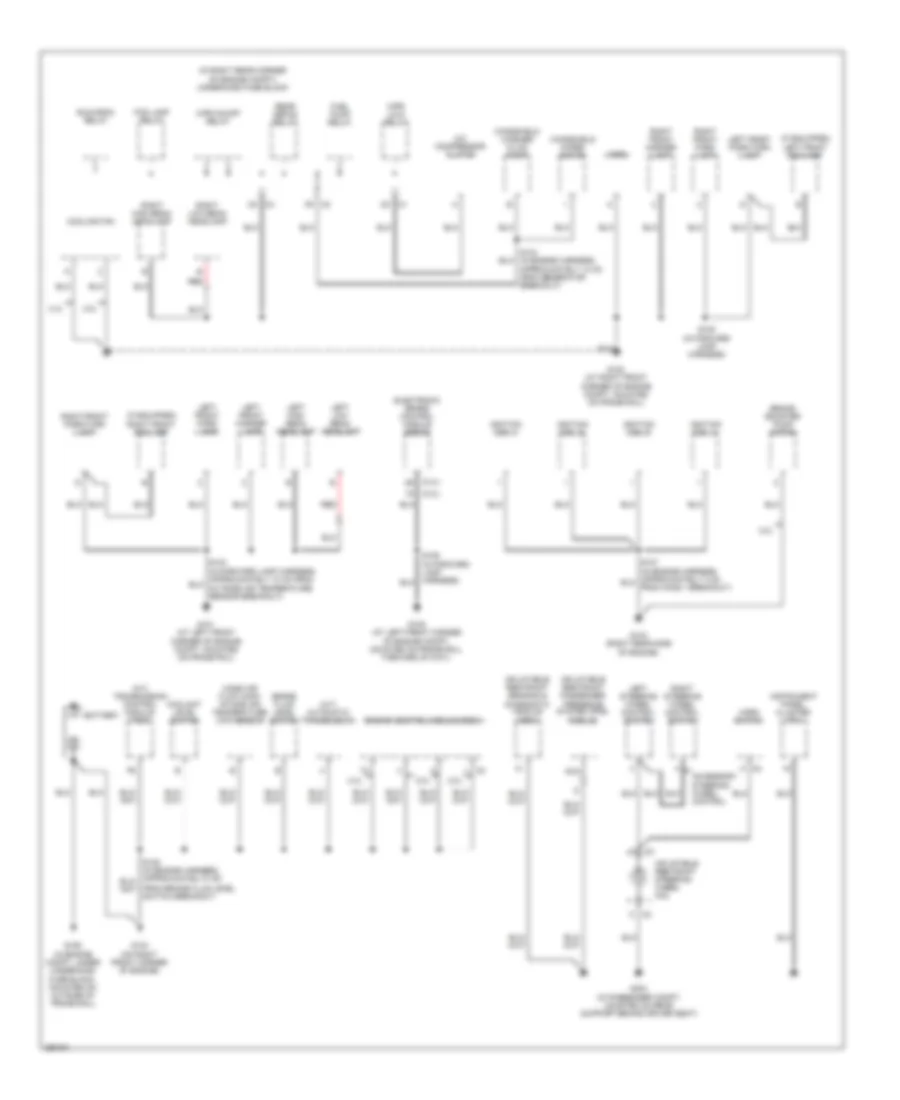
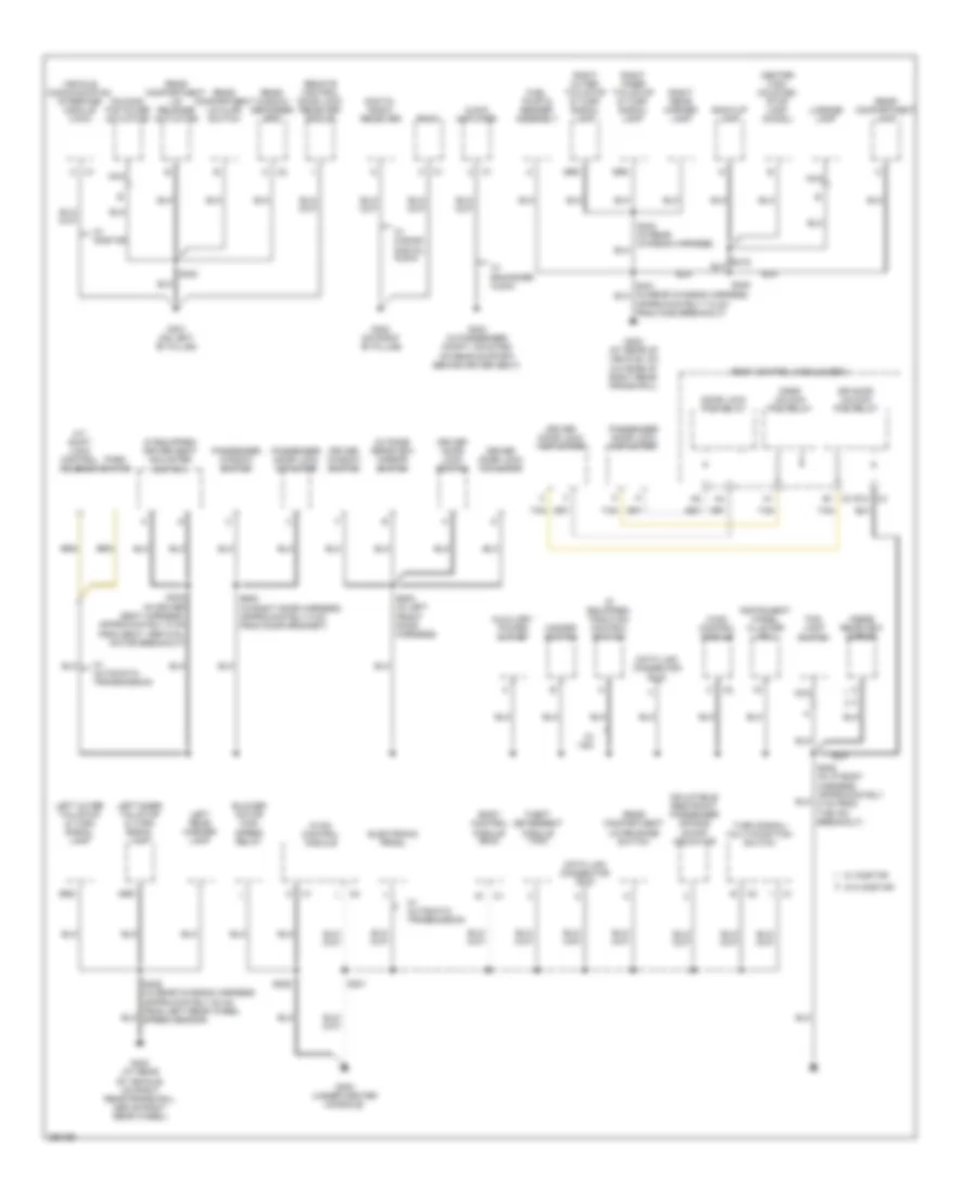
GROUND DISTRIBUTION
Ground Distribution Wiring Diagram (1 of 2) for Saturn Sky 2007
List of elements for Ground Distribution Wiring Diagram (1 of 2) for Saturn Sky 2007:
- (2.0l)
- (2.4l)
- (a/t) automatic transmission
- (a/t) transmission control module (tcm)
- (if equipped)
- (in right rear corner of engine compt) underhood fuse block
- 2.0l
- 2.4l
- A c2
- A/c compressor clutch
- Accessory steering wheel control
- Approximately 12 cm from generator breakout)
- Battery
- Brake booster pump motor
- Brake fluid level switch
- C1 d3
- C2 f9
- C3 c5
- Coolant level switch
- Cooling fan
- Electronic brake control module (ebcm)
- Engine control module (ecm)
- Fog lamp relay
- From brake fluid level switch breakout)
- Fuel pump relay
- G101 (at left front corner of engine compt, mounted on frame rail)
- G102 (at right front corner of engine compt, mounted on frame rail)
- G103 (right rear side of engine)
- G104 (on right front corner of engine)
- G105 (at left front corner of engine compt, mounted on frame rail, forward of g101)
- G106 (in engine compt, under underhood fuse block, mounted on outside of frame rail)
- G304 (in passenger compt, mounted on rear support behind driver seat)
- Horn
- Horn switch
- Ignition coil 1
- Ignition coil 2
- Ignition coil 3
- Ignition coil 4
- Inflatable restraint passenger presence system (pps) module
- Inflatable restraint sensing & diagnostic module (sdm)
- Inflatable restraint steering wheel coil
- Instrument panel cluster (ipc)
- Left front fog lamp
- Left front marker lamp
- Left front park lamp
- Left front park/turn lamp
- Left high beam headlamp
- Left low beam headlamp
- Left steering wheel control switch
- Mass air flow (maf)/ intake air temperature (iat) sensor
- Nca
- Rear defog relay
- Red
- Right front fog lamp
- Right front marker lamp
- Right front park lamp
- Right front park/turn lamp
- Right high beam headlamp
- Right low beam headlamp
- Right steering wheel control switch
- Run/crnk relay
- S105 (in forward lamp harness)
- Windshield washer fluid pump
- Windshield wiper motor
- Wpr lo/hi relay
- Wpr on/off relay
Ground Distribution Wiring Diagram (2 of 2) for Saturn Sky 2007
List of elements for Ground Distribution Wiring Diagram (2 of 2) for Saturn Sky 2007:
- (if equipped) driver seat adjuster switch
- (if equipped) traction control switch
- A/t shift lock control solenoid
- Approximately 7.5 cm from c406 breakout)
- Audio amplifier
- Auxiliary power outlet
- B1 c3
- Back-up lamp
- Blower motor high speed relay
- Body control module (bcm)
- C4 e12
- Center high mounted stop lamp (chmsl)
- Data link connector (dlc)
- Digital radio receiver
- Door lock pcb relay
- Door unlock pcb relay
- Dr door unlock pcb relay
- Driver door lock actuator
- Driver door lock switch
- Driver window switch
- Electronic prndl
- Fog lamp switch
- Folding top cover actuator
- Fuel pump & sender assembly
- G300 (under center console)
- G301 (on left "b" pillar)
- G302 (on right "b" pillar)
- G303 (in passenger compt, mounted on rear support behind driver seat)
- G400 (at rear of vehicle, on right rear frame rail, above right rear wheel)
- G402 (at rear of vehicle, on outside of right rear frame rail)
- Grd
- Hazard switch
- Hvac control module
- Inflatable restraint passenger air bag on/off indicator
- Inside rearview mirror
- Instrument panel cluster (ipc)
- Left inner tail/stop & turn signal lamp
- Left outer tail/stop & turn signal lamp
- Left rear marker lamp
- License lamp
- Nca
- Outside rearview mirror switch
- Park switch
- Passenger door lock actuator
- Passenger window switch
- Radio
- Rear compartment lamp
- Rear compartment lid ajar switch
- Rear compartment lid release actuator
- Rear compartment lid release switch
- Rear window defogger grid
- Remote control door lock receiver (rcdlr)
- Right inner tail/stop & turn signal lamp
- Right outer tail/stop & turn signal lamp
- Right rear marker lamp
- S226
- S301
- S302 (in driver seat harness, approximately 5 cm from seat vertical motor breakout)
- S400
- S405 (in rear chassis harness, approximately 82 cm from left rear wheel speed sensor)
- S408
- S500 (in left front door harness)
- S600 (in right door harness, approximately 8 cm from door grommet)
- Tan
- Theft deterrent module (tdm)
- Turn signal/ multi-function switch
- Vehicle communication interface module (vcim)
- W/ automatic transmission
- W/ enhanced audio
- W/ onstar
- W/ s band digital audio
- W/ vsc
- W/o onstar
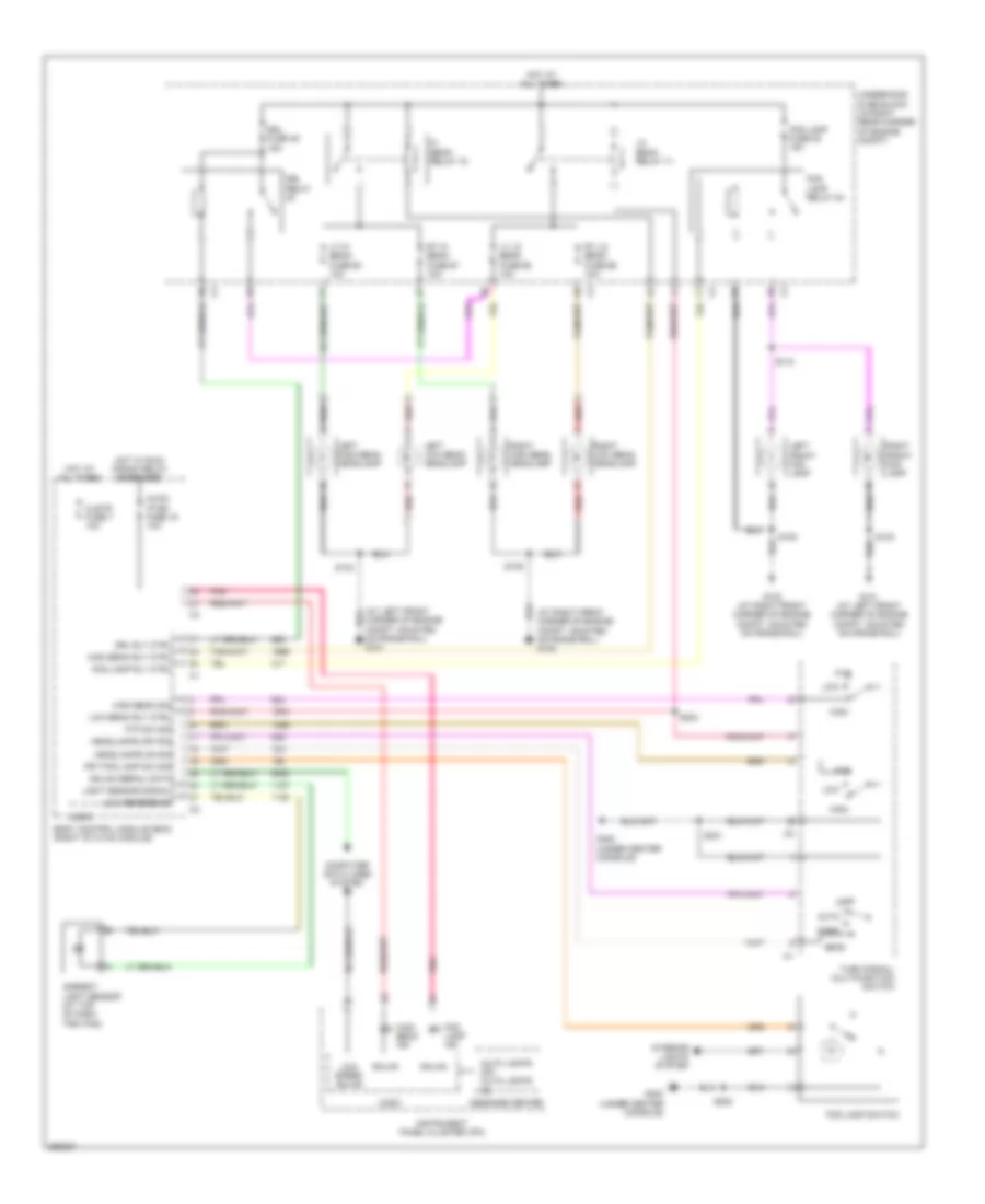
HEADLIGHTS
Headlights Wiring Diagram for Saturn Sky 2007
List of elements for Headlights Wiring Diagram for Saturn Sky 2007:
- (at left front corner of engine compt, mounted on frame rail) g101
- (at right front corner of engine compt, mounted on frame rail) g102
- Ambient light sensor (at top of dash trim pad)
- Auto
- Auto lights off auto lights on
- Body control module (bcm) (right of hvac module)
- Clstr fuse 7 10a
- Computer data lines system
- Drl fuse 49 15a
- Drl relay
- Drl rly ctrl
- Fog lamp fuse 53 15a
- Fog lamp ind
- Fog lamp relay 54
- Fog lamp rly ctrl
- Fog lamp switch
- Frt fog lamp sw sig
- Ftp
- Ftp sw sig
- G101 (at left front corner of engine compt, mounted on frame rail)
- G102 (at right front corner of engine compt, mounted on frame rail)
- G300 (under center console)
- Gmlan
- Gmlan serial data
- Head
- Headlamps off sig
- Headlamps on sig
- Hi beam relay 72
- High
- High beam ind
- High beam rly ctrl
- High beam sig
- Hot at all times
- Hot w/ run/ crank relay energized
- Hvac/ ip ign fuse 16 10a
- Instrument panel cluster (ipc)
- Interior lights system
- Left front fog lamp
- Left high beam headlamp
- Left low beam headlamp
- Light sensor signal
- Lo beam relay 71
- Logic
- Low
- Low beam rly ctrl
- Low reference
- Low speed gmlan
- Lt hi beam fuse 63 10a
- Lt lo beam fuse 65 10a
- Message center
- Off
- Park
- Pnk
- Red
- Red a
- Right front fog lamp
- Right high beam headlamp
- Right low beam headlamp
- Rt hi beam fuse 67 10a
- Rt lo beam fuse 66 10a
- S103
- S105
- S115
- S204
- S208
- S301
- Turn signal/ multifunction switch
- Underhood fuse block (in right rear corner of engine compt)
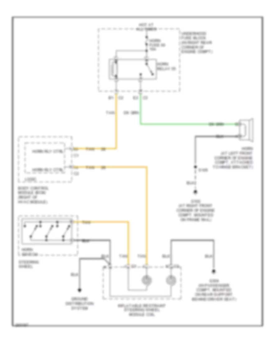
HORN
Horn Wiring Diagram for Saturn Sky 2007
List of elements for Horn Wiring Diagram for Saturn Sky 2007:
- B1 c2
- Body control module (bcm) (right of hvac module)
- E2 c3
- G102 (at right front corner of engine compt, mounted on frame rail)
- G304 (in passenger compt, mounted on rear support behind driver seat)
- Ground distribution system
- Horn (at left front corner of engine compt, attached to hinge bracket)
- Horn fuse 60 10a
- Horn relay 55
- Horn rly ctrl
- Horn switch
- Hot at all times
- Inflatable restraint steering wheel module coil
- Logic
- S105
- Steering wheel
- Tan
- Underhood fuse block (in right rear corner of engine compt)
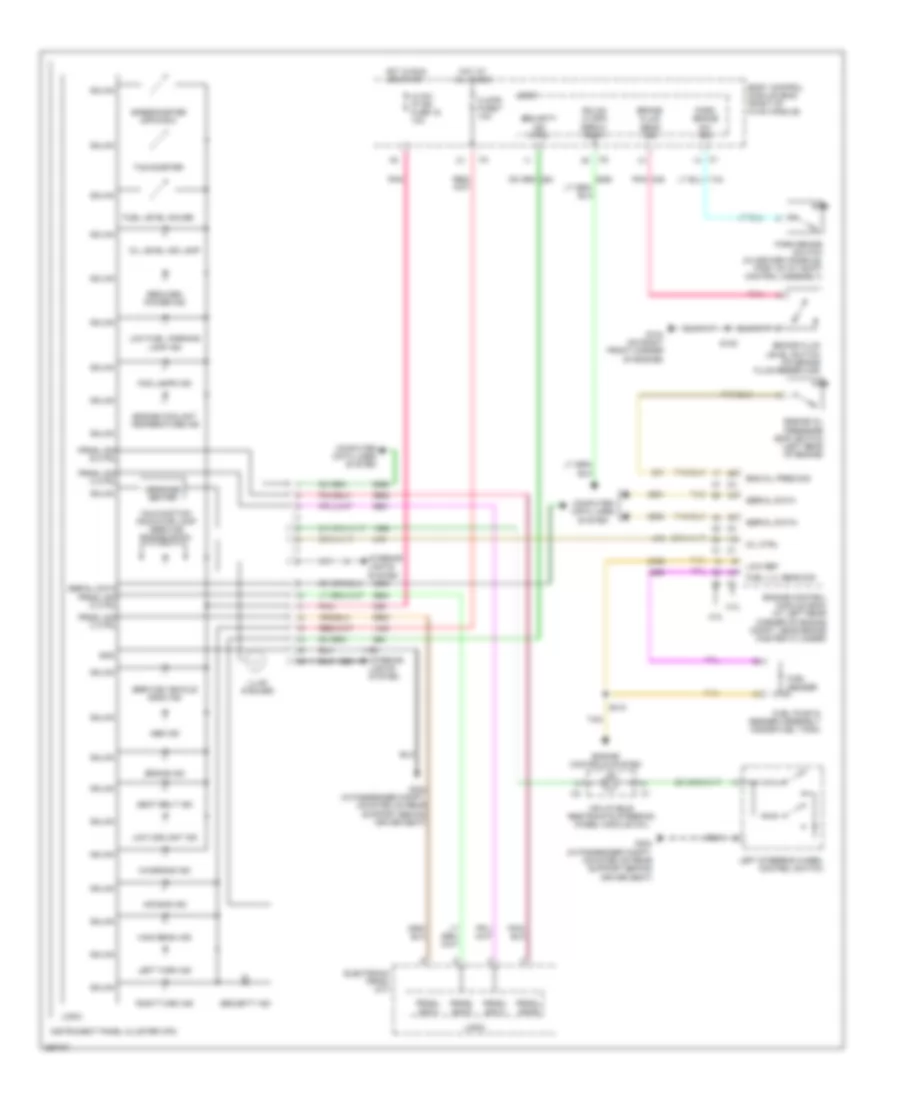
INSTRUMENT CLUSTER
Instrument Cluster Wiring Diagram for Saturn Sky 2007
List of elements for Instrument Cluster Wiring Diagram for Saturn Sky 2007:
- 2.0l
- 2.4l
- Abs ind
- Air bag ind
- Body control module (bcm) (right of hvac module)
- Brake fluid level switch (on brake fluid reservoir)
- Brake fluid sens sig
- Brake ind
- Charging ind
- Clstr fuse 7 10a
- Computer data lines system
- Electronic prndl (a/t)
- Eng oil pres sig
- Engine control module (ecm) (at left rear corner of engine compt, near brake master cylinder)
- Engine controls system
- Engine coolant temperature ind
- Engine oil pressure (eop) switch (left rear of engine)
- Fog lamps ind
- Fuel level gauge
- Fuel lvl sens sig
- Fuel pump & sender assembly (inside fuel tank)
- Fuel sender
- G104 (on right front corner of engine)
- G304 (in passenger compt, mounted on rear support behind driver seat)
- Gmlan
- Gmlan lo spd serial data
- Gnd
- High beam ind
- Hot at all times
- Hot in run or start
- Hvac/ ip ign fuse 16 10a
- Illum (6 bulbs)
- Inflatable restraints steering wheel module coil
- Instrument panel cluster (ipc)
- Interior lights system
- Left steering wheel control switch
- Left turn ind
- Logic
- Low coolant ind
- Low fuel warning lamp ind
- Low ref
- Malfunction indicator lamp (service engine soon)
- Message center
- Mil ctrl
- Oil level ind lamp
- Park brake sw sig
- Park brake switch (in center console, part of a/t shift control assembly)
- Pnk
- Prndl sig a
- Prndl sig a ctrl
- Prndl sig b
- Prndl sig b ctrl
- Prndl sig c
- Prndl sig c ctrl
- Prndl sig d
- Prndl sig d ctrl
- Reduced power ind
- Right turn ind
- S108
- S410
- Seat belt ind
- Security ind
- Security ind ctrl
- Serial data
- Serial data+
- Serial data-
- Service vehicle soon ind
- Speedometer (mph/kmh)
- Tachometer
- Tan
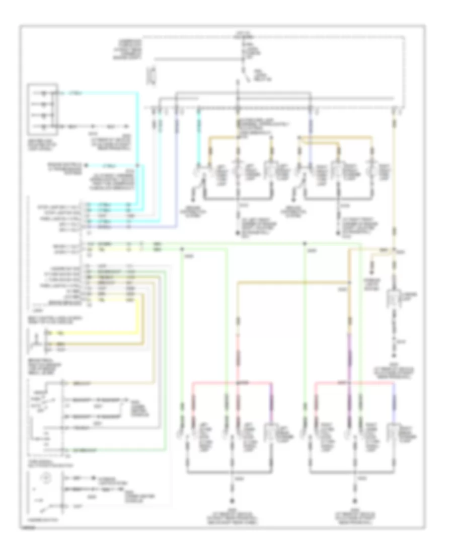
INTERIOR LIGHTS
Courtesy Lamps Wiring Diagram for Saturn Sky 2007
List of elements for Courtesy Lamps Wiring Diagram for Saturn Sky 2007:
- (sky) s408
- (w/o all doors power operated) s208
- A10
- Body control module (bcm) (right of hvac module)
- Courtesy lamp ctrl
- Door
- Door ajar
- Driver door lock actuator (inside center rear of left door)
- Driver information center (dic) (solstice) message center (sky)
- G300 (under center console)
- G301 (on left "b" pillar)
- G402 (at rear of vehicle, on outside of right rear frame rail)
- Gnd
- Hot at all times
- Inadvertent load control pcb relay
- Inside rearview mirror
- Instrument panel cluster (ipc)
- Int lights fuse 27 10a
- Lf dr ajar sw sig
- Logic
- Nca
- Off
- Passenger door lock actuator (inside center rear of right door)
- Rear compartment lamp
- Rear compartment lid ajar switch (below rear window)
- Rear compt ajar
- Rear compt lamp
- Rf dr ajar sw sig
- Rly ctrl
- S207 (solstice)
- S208
- S301 (sky)
- S311 (solstice)
- S400 (sky)
- S403 (solstice)
- S500
- S500 (w/ all doors power operated)
- S600
- S600 (w/ all doors power operated)
- Serial data
- Sky
- Solstice
- Splice pack sp200 (in the passenger compt, behind lower right trim panel)
- W/ onstar
- W/o onstar
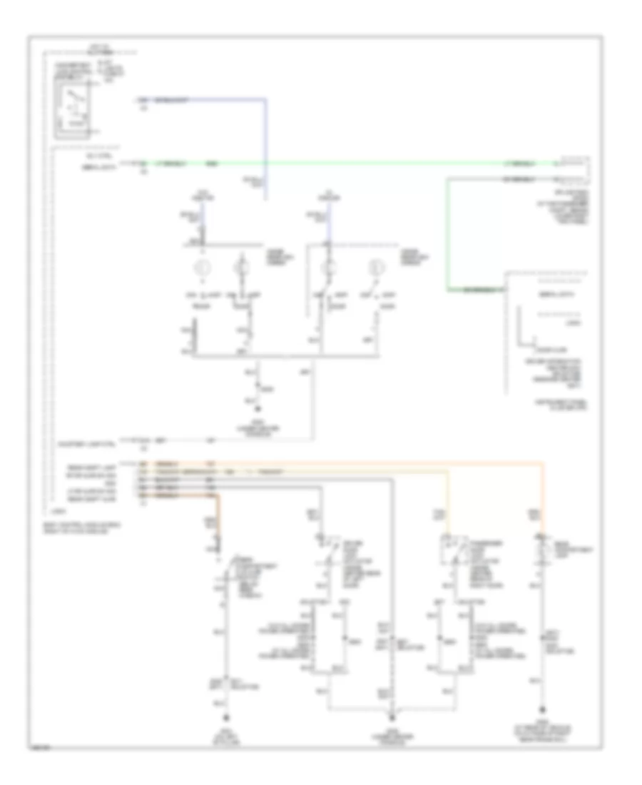
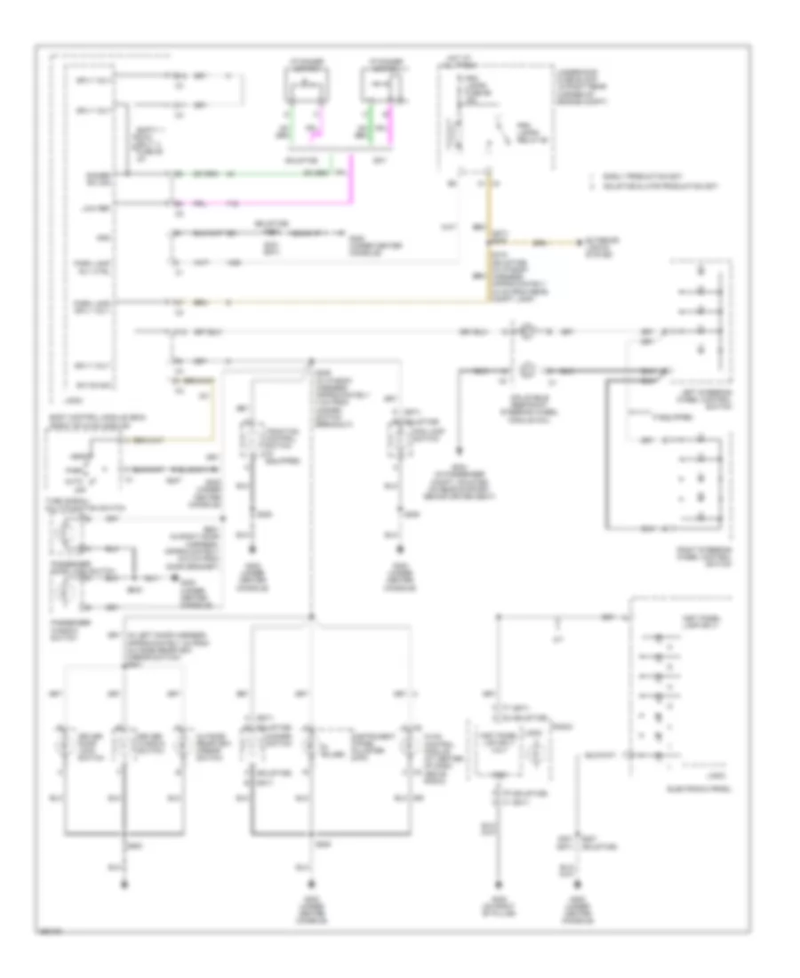
Instrument Illumination Wiring Diagram for Saturn Sky 2007
List of elements for Instrument Illumination Wiring Diagram for Saturn Sky 2007:
- (6 bulbs)
- (sky)
- (sky) b
- (sky) s200
- (solstice)
- (solstice) s207
- A (sky)
- A (solstice)
- A/t
- Auto
- B (solstice)
- B12
- Body control module (bcm) (right of hvac module)
- C c2
- C11
- C12
- C4 a1
- D (sky)
- D c2
- Dimmer sw sig
- Driver door lock switch
- Driver window switch
- Early production sky
- Electronic prndl
- Empty swc bklt fuse 28 2a
- Exterior lights system
- Fog lamp switch
- G300 (under center console)
- G302 (on right "b" pillar)
- G304 (in passenger compt, mounted on rear support behind driver seat)
- Gnd
- Hazard switch
- Head
- Hot at all times
- Hvac control module (at center of dash, above radio)
- I/p dimmer switch
- If equipped
- Inflatable restraint steering wheel module coil
- Inst panel lamp sply
- Inst panel lmp sply volt
- Instrument panel cluster (ipc)
- Left steering wheel control switch
- Logic
- Low ref
- Off
- Outside rearview mirror switch
- Park
- Park lamp rly ctrl
- Park lamp sply volt
- Passenger door lock switch
- Passenger window switch
- Prk lamps fuse 69 15a
- Prk lamps relay 68
- Radio
- Right steering wheel control switch
- S207
- S207 (solstice)
- S208
- S209 (in i/p body harness, approximately 4 cm from hazard switch breakout)
- S301 (sky)
- S415 (solstice) (in i/p body harness, approximately 33 cm from rear compt lamp)
- S500
- S600
- S601 (in right door harness, approximately 15.5 cm from door grommet)
- Sky
- Solstice
- Solstice & late production sky
- Sply volt
- Sw on sig
- Traction control switch (if equipped)
- Turn signal/ multi-function switch
- Underhood fuse block (in right rear corner of engine compt)
POWER DISTRIBUTION
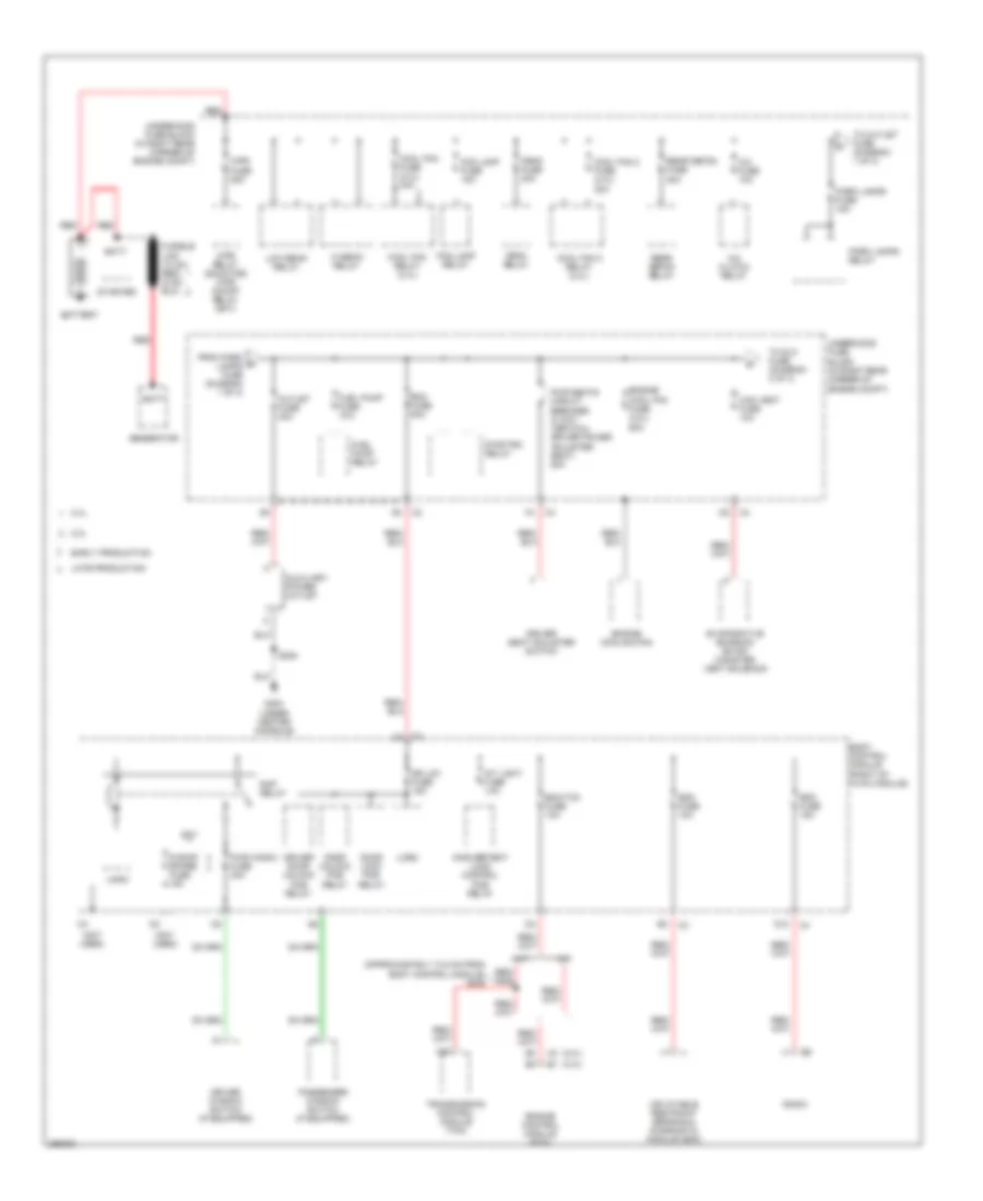
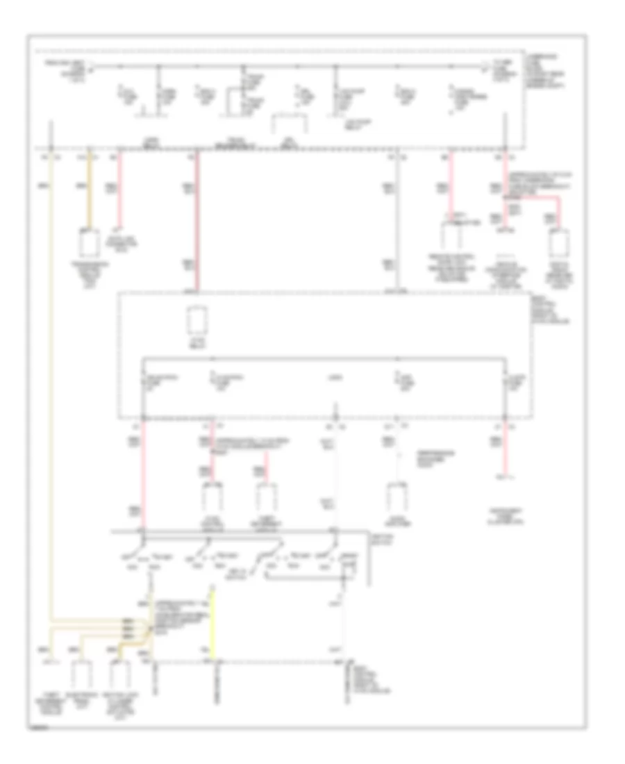
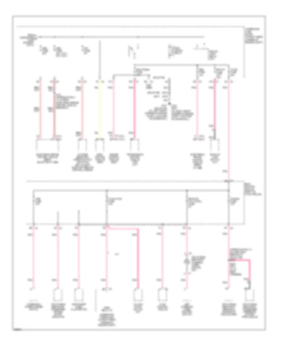
Power Distribution Wiring Diagram (1 of 3) for Saturn Sky 2007
List of elements for Power Distribution Wiring Diagram (1 of 3) for Saturn Sky 2007:
- (2.0l)
- (2.4l)
- (approximately 13.5 cm from body control module) s206
- (not used)
- 2.0l
- 2.4l
- A/c clutch relay
- A/c fuse 10a
- A/t
- Auxiliary power outlet
- Batt
- Battery
- Bcm fuse 50a
- Body control module (right of hvac module)
- C3 d1
- Can vent fuse 10a
- Cool fan 2 fuse (2.4l) 30a
- Cool fan 2 relay (2.4l)
- Cool fan fuse (2.4l) 30a
- Cool fan relay (2.4l)
- Crnk fuse 30a
- Crnk relay
- D10
- Door lock pcb relay
- Door unlock pcb relay
- Dr lck fuse 15a
- Driver door unlock pcb relay
- Driver seat adjuster switch
- Driver window switch (if equipped)
- Early production
- Ecm/tcm fuse 10a
- Engine control module (ecm)
- Engine cool fan fuse (2.0l) 60a
- Engine cooling fan
- Evaporative emission (evap) canister vent solenoid
- F27
- Fog lamp fuse 15a
- Fog lamp relay
- From park a lamps fuse (diagram 1 of 3)
- Fuel pump fuse 15a
- Fuel pump relay
- G300 (under center console)
- Generator
- Hi beam relay
- Inadvertent load control pcb relay
- Inflatable restraint sensing & diagnostic module (sdm)
- Int light fuse 10a
- Late production
- Logic
- Low beam relay
- M/t
- Outlet fuse 20a
- Park lamps fuse 15a
- Park lamps relay
- Passenger window switch (if equipped)
- Pwr seats circuit breaker (2 way vertical driver power adjuster seat) 20a
- Pwr wndw fuse 30a
- Pwr/trn relay
- Radio
- Rap relay
- Rdo fuse 15a
- Rear defog fuse 20a
- Rear defog relay
- Red
- S roof spare fuse 15a
- S208
- Sdm fuse 10a
- Sky
- Starter
- To dlc fuse (diagram 2 of 3)
- To outlet fuse (diagram 1 of 3)
- Transmission control module (tcm)
- Underhood fuse block (in right rear corner of engine compt)
- Wpr fuse 25a
- Wpr relay (solstice) wpr on/off relay (sky)
Power Distribution Wiring Diagram (2 of 3) for Saturn Sky 2007
List of elements for Power Distribution Wiring Diagram (2 of 3) for Saturn Sky 2007:
- (approximately 67.5 cm from underhood fuse block breakout) (solstice) s136
- (approximately 7 cm from accelerator pedal position sensor breakout) s216
- (sky)
- (solstice)
- A12
- Acc
- Acc vlt sig
- Amp fuse 20a
- Audio amplifier
- Bcm 2 fuse 40a
- Bcm 3 fuse 30a
- Body control module (right of hvac module)
- Clstr fuse 10a
- D10
- D11
- D12
- Data link connector (dlc)
- Digital radio receiver (w/ digital audio)
- Dlc fuse 15a
- Drl fuse 15a
- Drl relay
- Electronic prndl (a/t)
- From can vent fuse b (diagram 1 of 3)
- Horn fuse 10a
- Horn relay
- Hvac control module
- Hvac relay
- Hvac/pk3+ fuse 10a
- Ign sw/pk3+ fuse 2a
- Ignition lock cylinder control actuator (a/t)
- Ignition switch
- Instrument panel cluster (ipc)
- Key in switch
- Logic
- Off
- Off run/crank
- Performance enhanced audio
- Remote control door lock receiver (rcdlr) (solstice: if equipped)
- Run
- Run/crank rly
- S band onstar/rke fuse 10a
- S202 (sky)
- Start
- Theft deterrent control module
- Theft deterrent module
- To abs fuse (diagram 3 of 3)
- Transmission control module (tcm) (a/t)
- Trunk fuse 25a
- Trunk fuse 5a
- Trunk release relay
- Underhood fuse block (in right rear corner of engine compt)
- Vac pump fuse (2.0l) 20a
- Vac pump relay
- Vehicle communication interface module (w/ onstar)
Power Distribution Wiring Diagram (3 of 3) for Saturn Sky 2007
List of elements for Power Distribution Wiring Diagram (3 of 3) for Saturn Sky 2007:
- (2.0l)
- (2.4l)
- (2.4l) (2.0l)
- (approximately 8 cm from g300 breakout) (solstice) s318
- (not used)
- (sky)
- (solstice)
- A/t
- A10
- A8 c3
- Abs fuse 10a
- Abs fuse 20a
- Abs fuse 30a 40a
- Air bag fuse 10a
- B11
- Back-up lamp switch (m/t)
- Bck/up fuse (m/t) 10a
- Bck/up lamp relay (a/t)
- Body control module (bcm)
- Body control module (right of hvac module)
- C12
- C3 d6
- Clutch start switch (m/t)
- Crnk relay 34
- E6 c4
- Ecm/trans fuse 15a
- Electronic brake control module (ebcm) (solstice w/ abs)
- Electronic brake control module (ebcm) (w/ abs)
- Engine control module (ecm)
- Eps/str whl cntrl fuse 2a
- From s band/rke c fuse (diagram 2 of 3)
- G101 (solstice) (at left front corner of engine compt, mounted on frame rail)
- G102 (sky) (at right front corner of engine compt, mounted on frame rail)
- Hvac control module
- Hvac/ip ign fuse 10a
- I/p ign fuse 20a
- Inflatable restraint passenger air bag on/off indicator
- Inflatable restraint passenger presence system (pps) module
- Inflatable restraint sensing & diagnostic module (sdm)
- Inflatable restraint steering wheel module coil
- Instrument panel cluster (ipc)
- Left steering wheel control switch
- Mir fuse 5a
- Nca
- Outside rearview mirror switch (solstice left & right electric remote control mirror)
- Pnk
- Run/ crank relay
- S103
- S105
- S205 (sky) (in i/p body harness)
- Solstice
- Transmission control module (tcm) (a/t)
- Underhood fuse block (in right rear corner of engine compt)
- Windshield wiper/washer switch
- Wpr fuse 10a
POWER DOOR LOCKS
Power Door Locks Wiring Diagram for Saturn Sky 2007
List of elements for Power Door Locks Wiring Diagram for Saturn Sky 2007:
- Batt pos volt
- Body control module (right of hvac module)
- Computer data lines system
- Door lock pcb relay
- Door unlock pcb relay
- Dr ajar
- Dr door unlock pcb relay
- Dr lck fuse 26 15a
- Dr lock ctrl
- Dr unlock ctrl
- Driver door lock actuator (inside center rear of left door)
- Driver door lock switch
- Driver information center (dic) (solstice)
- Drv dr ajar pass dr ajar
- Drv dr lock rly unlock ctrl
- E12
- E6 c4
- G300 (under center console)
- G301 (on left "b" pillar)
- Gmlan serial data
- Ground
- Hot at all times
- Instrument panel cluster (ipc)
- Interior lights system
- Key fob batt low
- Lf dr ajar sw sig
- Lock
- Logic
- Low spd
- Low spd gmlan serial data
- Message center
- Message center (sky)
- Message request
- Passenger door lock actuator (inside center rear of right door)
- Passenger door lock switch
- Rear compt lock actuator unlock
- Remote control door lock receiver (rcdlr) (behind driver seat, to right center of rear support)
- Rf dr ajar sw sig
- S band onstar/pke fuse 56 10a
- S208
- S500
- S500 (w/ power window)
- S600
- S600 (w/ power window)
- Sky
- Solstice
- Tan
- Trunk, tailgate, fuel doors system
- Underhood fuse block (in right rear corner of engine compt)
- Unlock
POWER MIRRORS
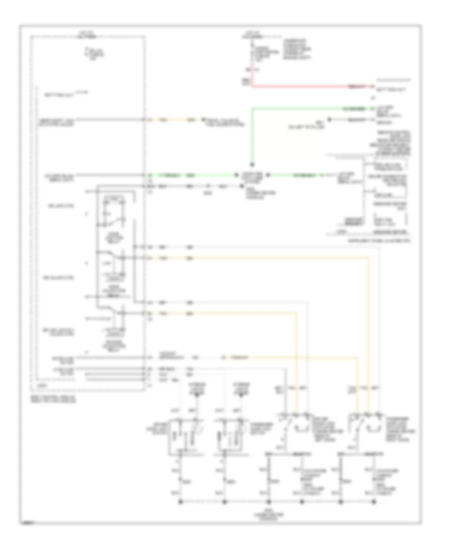
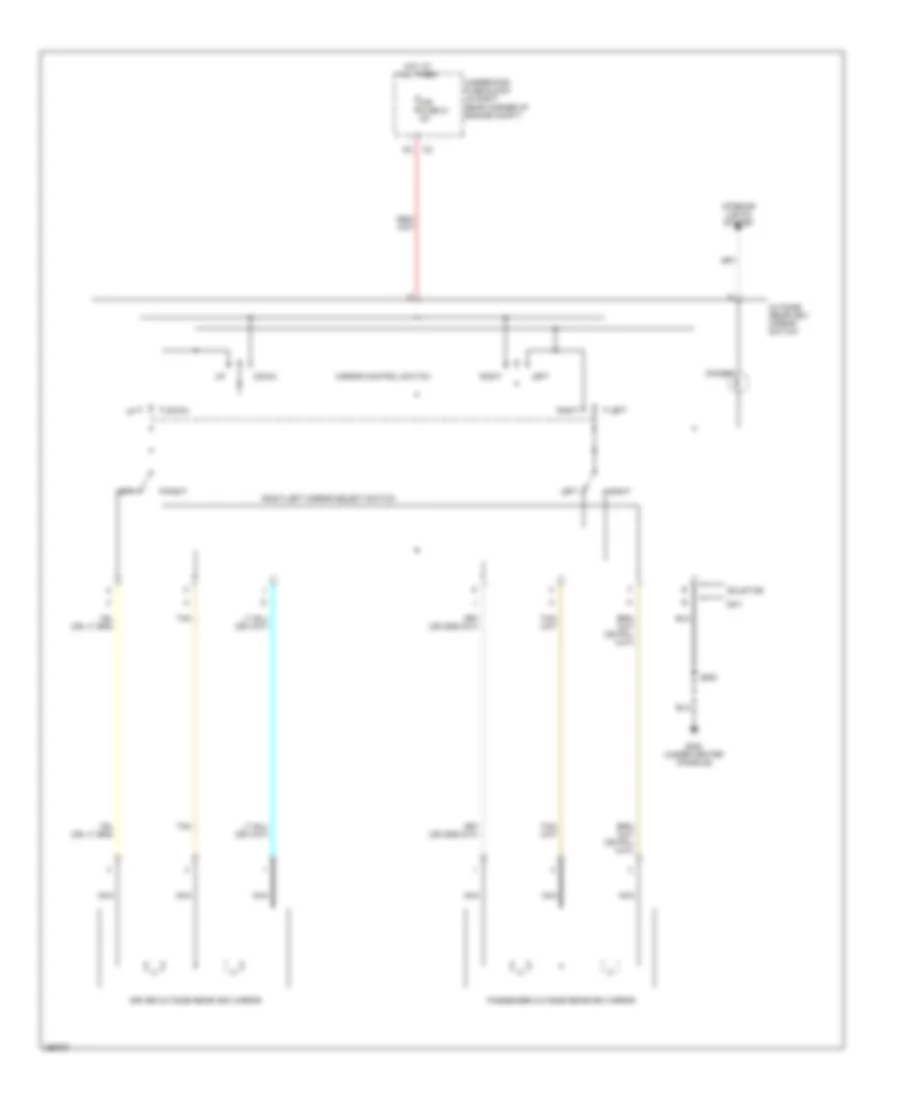
Power Mirrors Wiring Diagram for Saturn Sky 2007
List of elements for Power Mirrors Wiring Diagram for Saturn Sky 2007:
- Dimmer
- Down
- Driver outside rearview mirror
- G300 (under center console)
- Hot at all times
- Interior lights system
- Left
- Mir fuse 21 5a
- Mirror control switch
- Nca
- Outside rearview mirror switch
- Passenger outside rearview mirror
- Right
- Right/left mirror select switch
- S500
- Sky
- Solstice
- Tan
- Underhood fuse block (in right rear corner of engine compt)
POWER SEATS
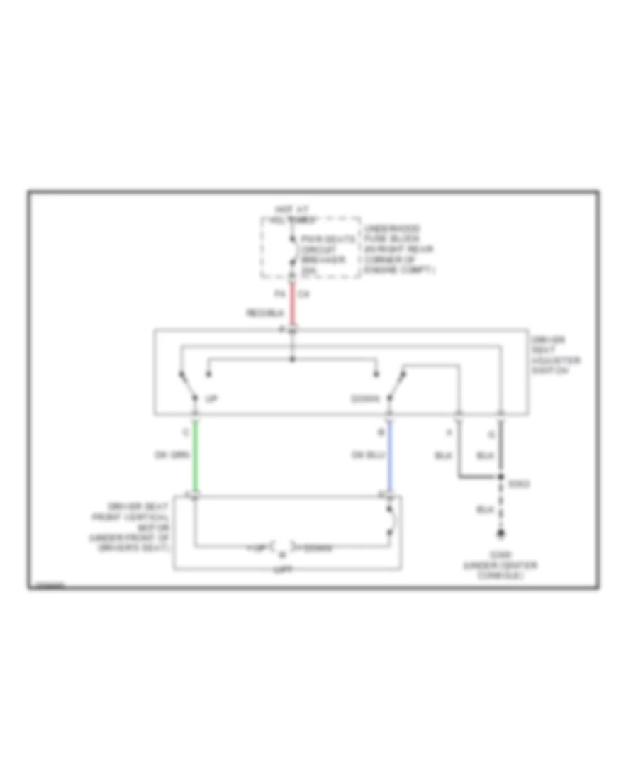
2-Way Adjustable Power Seat Wiring Diagram for Saturn Sky 2007
List of elements for 2-Way Adjustable Power Seat Wiring Diagram for Saturn Sky 2007:
- + down
- + up
- Down
- Driver seat adjuster switch
- Driver seat front vertical motor (under front of driver's seat)
- G300 (under center console)
- Hot at all times
- Lift
- Pwr seats circuit breaker 20a
- S302
- Underhood fuse block (in right rear corner of engine compt)
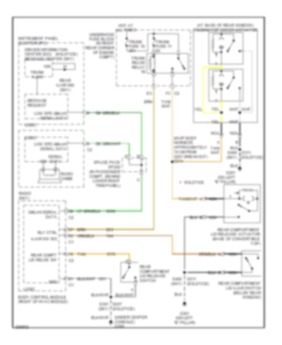
POWER TOP/SUNROOF
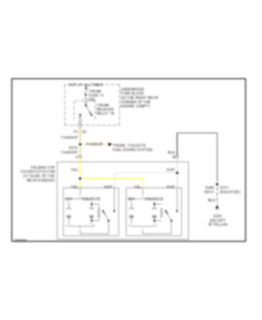
Power Top/Sunroof Wiring Diagram for Saturn Sky 2007
List of elements for Power Top/Sunroof Wiring Diagram for Saturn Sky 2007:
- Folding top cover actuator (at base of the rear window)
- G301 (on left "b" pillar)
- Hot at all times
- S214
- S311 (solstice)
- S400 (sky)
- Sky
- Solstice
- Trunk fuse 11 25a
- Trunk release relay 18
- Trunk, tailgate, fuel doors system
- Underhood fuse block (in the right rear corner of the engine compt)
POWER WINDOWS
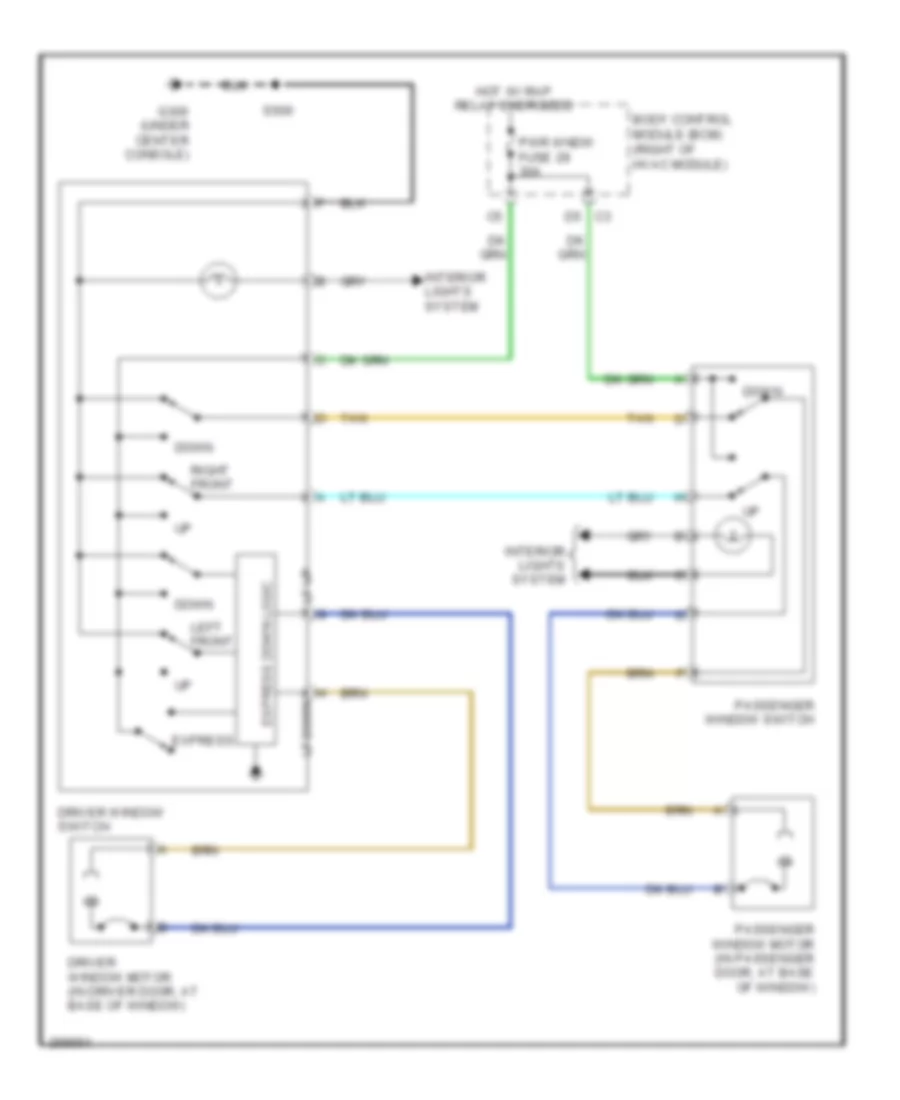
Power Windows Wiring Diagram for Saturn Sky 2007
List of elements for Power Windows Wiring Diagram for Saturn Sky 2007:
- Body control module (bcm) (right of hvac module)
- D5 c3
- Down
- Driver window motor (in driver door, at base of window)
- Driver window switch
- Express
- Express down logic
- G300 (under center console)
- Hot w/ rap relay energized
- Interior lights system
- Left front
- Lf down
- Lf up
- Passenger window motor (in passenger door, at base of window)
- Passenger window switch
- Pwr wndw fuse 29 30a
- Right front
- S500
- Tan
RADIO
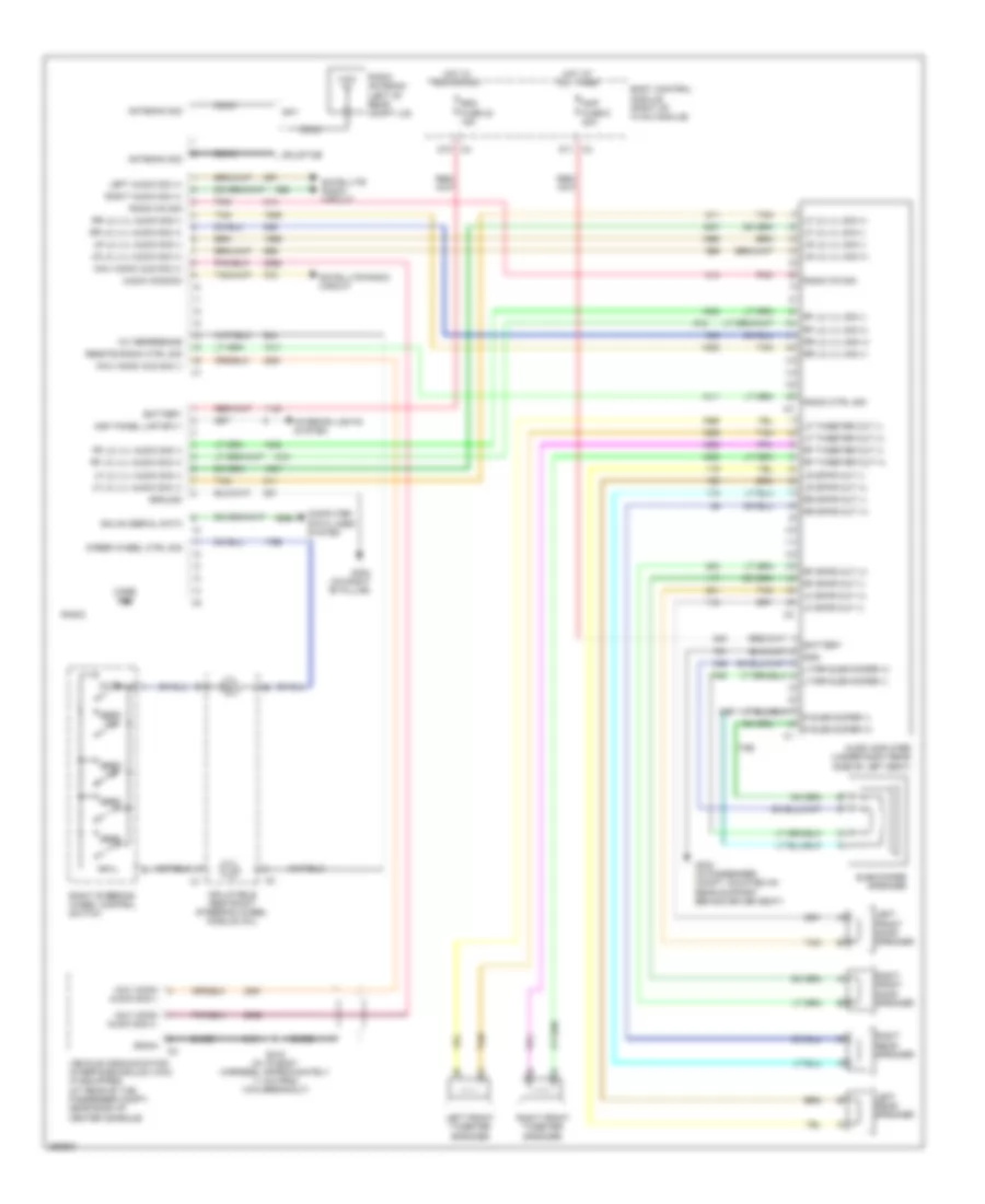
Radio Wiring Diagram, with Amplifier for Saturn Sky 2007
List of elements for Radio Wiring Diagram, with Amplifier for Saturn Sky 2007:
- 10v reference
- Amp fuse 6 20a
- Antenna sig
- Audio amplifier (under right rear side of left seat)
- Audio common
- Bare
- Battery
- Body control module (right of hvac module)
- Case gnd
- Coax
- Computer data lines system
- D10 c4
- D11 c3
- Drain
- G302 (on right "b" pillar)
- G303 (in passenger compt, mounted on rear support behind driver seat)
- Gmlan serial data
- Gnd
- Ground
- Hot at all times
- Hot in run or acc
- Inflatable restraint steering wheel module coil
- Inst panel lmp sply
- Interior lights system
- Left audio sig (+)
- Left front door speaker
- Left front tweeter speaker
- Left rear speaker
- Lf lo lvl audio sig (+)
- Lf lo lvl audio sig (-)
- Lf lo lvl sig (+)
- Lf lo lvl sig (-)
- Lf spkr out (+)
- Lf spkr out (-)
- Lf tweeter out (+)
- Lf tweeter out (-)
- Lr lo lvl audio sig (+)
- Lr lo lvl audio sig (-)
- Lr lo lvl sig (+)
- Lr lo lvl sig (-)
- Lr spkr out (+)
- Lr spkr out (-)
- Lt/rr subwoofer (+)
- Lt/rr subwoofer (-)
- Mute
- Navi mono aud sig (+)
- Navi mono aud sig (-)
- Navi mono audio sig (+)
- Navi mono audio sig (-)
- Pnk
- R subwoofer (+)
- R subwoofer (-)
- Radio
- Radio antenna (left of rear compt lid)
- Radio ctrl sig
- Radio on sig
- Rdo fuse 23 15a
- Remote radio ctrl sig
- Rf lo lvl audio sig (+)
- Rf lo lvl audio sig (-)
- Rf lo lvl sig (+)
- Rf lo lvl sig (-)
- Rf spkr out (+)
- Rf spkr out (-)
- Rf tweeter out (+)
- Rf tweeter out (-)
- Right audio sig (+)
- Right front door speaker
- Right front tweeter speaker
- Right rear speaker
- Right steering wheel control switch
- Rr lo lvl audio sig (+)
- Rr lo lvl audio sig (-)
- Rr lo lvl sig (+)
- Rr lo lvl sig (-)
- Rr spkr out (+)
- Rr spkr out (-)
- S315 (in i/p body harness, approximately 11 cm from vcim breakout)
- Satellite radio circuit
- Seek +
- Seek -
- Seek dn
- Seek up
- Sky
- Solstice
- Steer wheel ctrl sig
- Subwoofer speaker
- Tan
- Vehicle communication interface module (vcim) (if equipped) (at rear of the passenger compt, near back of center console)
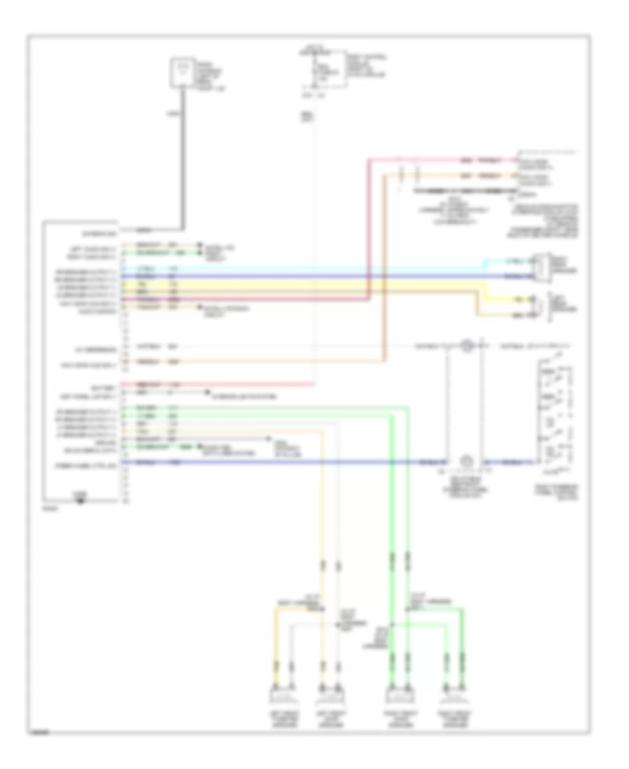
Radio Wiring Diagram, without Amplifier for Saturn Sky 2007
List of elements for Radio Wiring Diagram, without Amplifier for Saturn Sky 2007:
- (in i/p body harness) s211
- (in i/p body harness) s221
- (in i/p body harness) s222
- 10v reference
- Antenna sig
- Audio common
- Bare
- Battery
- Body control module (right of hvac module)
- Case gnd
- Coax
- Computer data lines system
- D10 c4
- Drain
- G302 (on right "b" pillar)
- Gmlan serial data
- Ground
- Hot in acc or run
- Inflatable restraint steering wheel module coil
- Inst panel lmp sply
- Interior lights system
- Left audio sig (+)
- Left front door speaker
- Left front tweeter speaker
- Left rear speaker
- Lf speaker output (+)
- Lf speaker output (-)
- Lr speaker output (+)
- Lr speaker output (-)
- Mute
- Navi mono aud sig (+)
- Navi mono aud sig (-)
- Navi mono audio sig (+)
- Navi mono audio sig (-)
- Radio
- Radio antenna (left of rear compt lid)
- Rdo fuse 23 15a
- Rf speaker output (+)
- Rf speaker output (-)
- Right audio sig (+)
- Right front door speaker
- Right front tweeter speaker
- Right rear speaker
- Right steering wheel control switch
- Rr speaker output (+)
- Rr speaker output (-)
- S212 (in i/p body harness)
- S315 (in i/p body harness, approximately 11 cm from vcim breakout)
- Satellite radio circuit
- Seek +
- Seek -
- Steer wheel ctrl sig
- Tan
- Vehicle communication interface module (vcim) (if equipped) (at rear of passenger compt, near back of center console)
- Vol dn
- Vol up
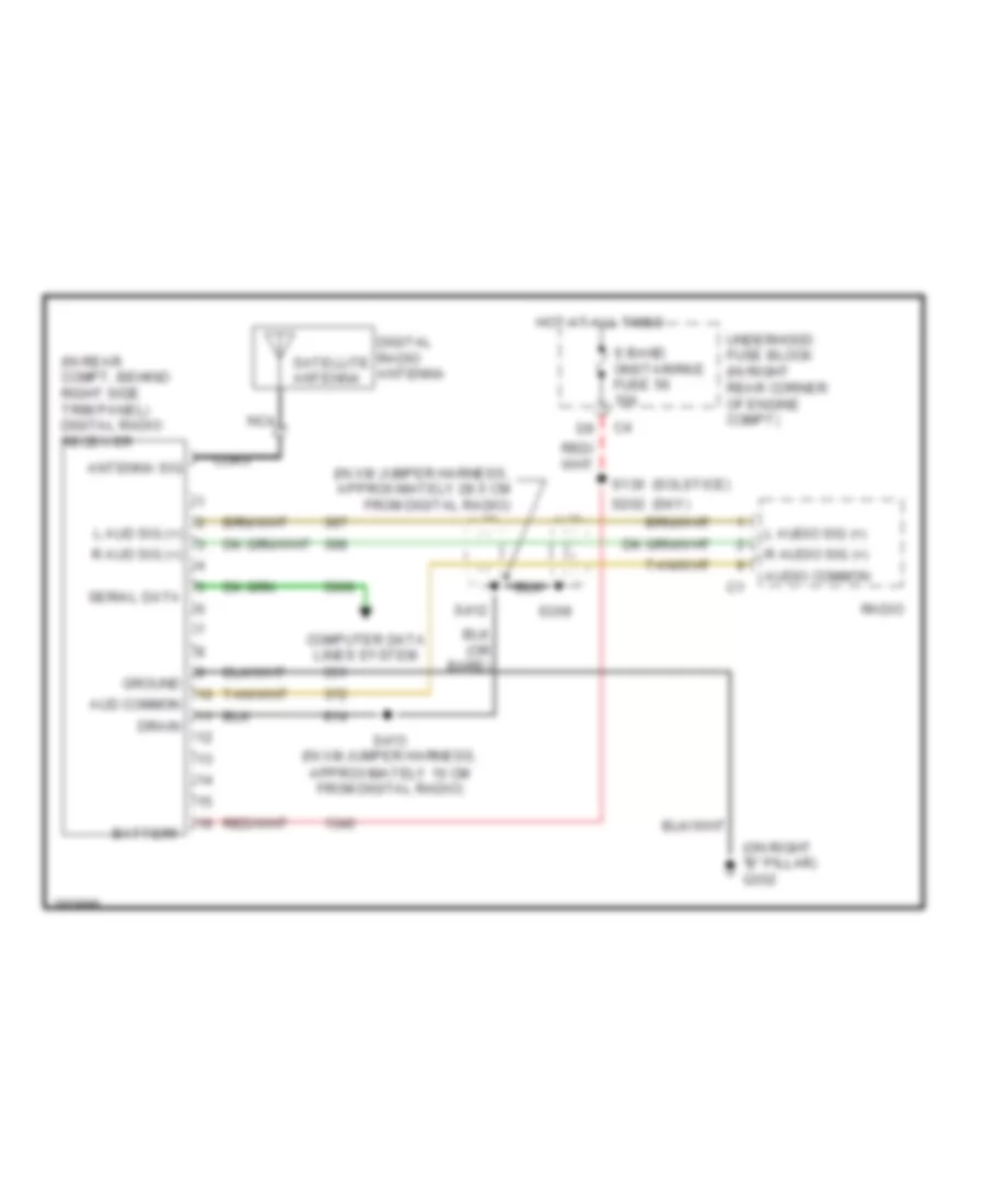
Satellite Radio Wiring Diagram for Saturn Sky 2007
List of elements for Satellite Radio Wiring Diagram for Saturn Sky 2007:
- (in rear compt, behind right side trim panel) digital radio receiver
- (in xm jumper harness, approximately 28.5 cm from digital radio)
- (on right "b" pillar) g302
- (sky)
- (solstice)
- Antenna sig
- Aud common
- Audio common
- Battery
- Coax
- Computer data lines system
- Digital radio antenna
- Drain
- Ground
- Hot at all times
- L aud sig (+)
- L audio sig (+)
- Nca
- R aud sig (+)
- R audio sig (+)
- Radio
- S band onstar/rke fuse 56 10a
- S136
- S202
- S309
- S412
- S413 (in xm jumper harness, approximately 10 cm from digital radio)
- Satellite antenna
- Serial data
- Underhood fuse block (in right rear corner of engine compt)
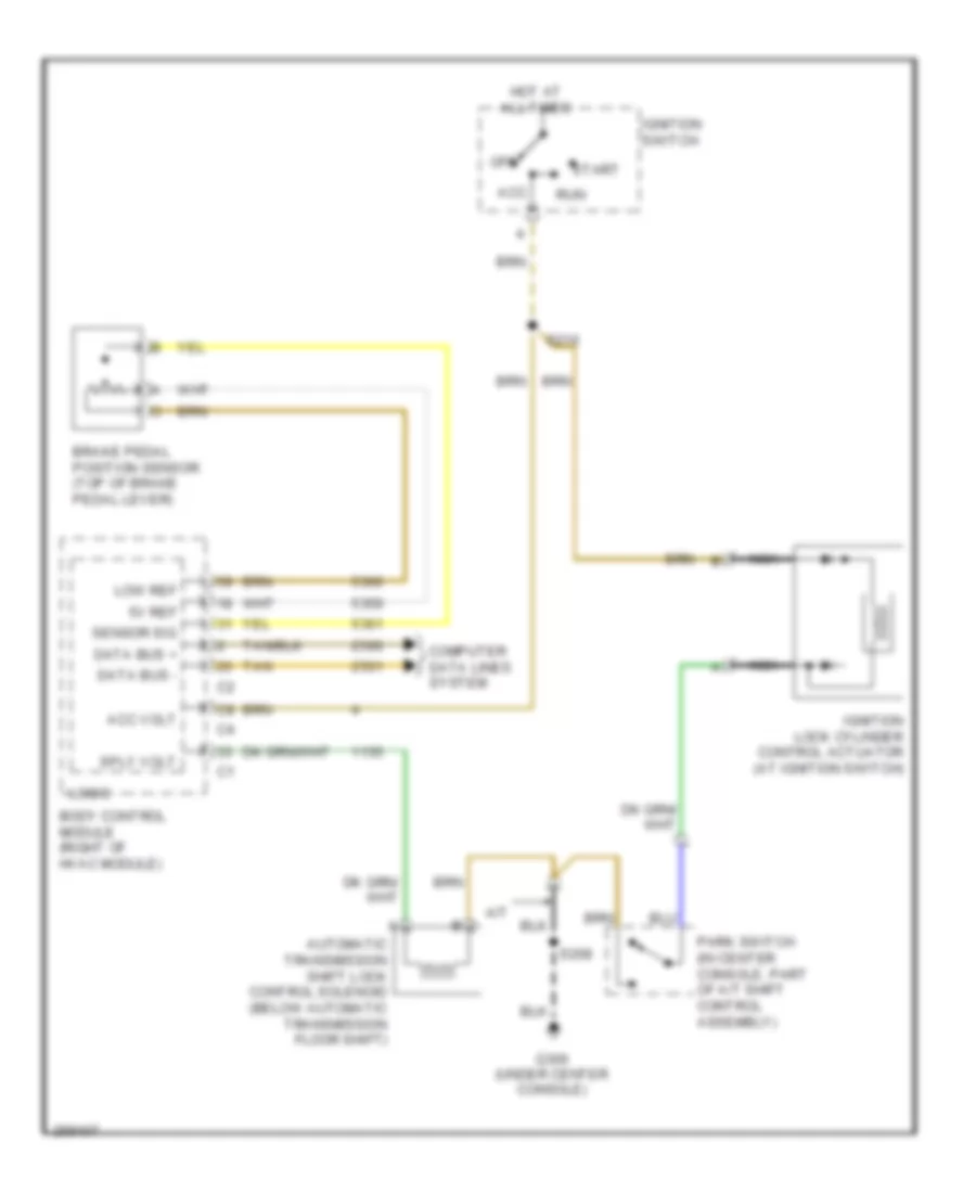
SHIFT INTERLOCK
Shift Interlock Wiring Diagram for Saturn Sky 2007
List of elements for Shift Interlock Wiring Diagram for Saturn Sky 2007:
- 5v ref
- A/t
- Acc
- Acc volt
- Automatic transmission shift lock control solenoid (below automatic transmission floor shift)
- Body control module (right of hvac module)
- Brake pedal position sensor (top of brake pedal lever)
- Computer data lines system
- Data bus +
- Data bus -
- G300 (under center console)
- Hot at all times
- Ignition lock cylinder control actuator (at ignition switch)
- Ignition switch
- Logic
- Low ref
- Nca
- Off
- Park switch (in center console, part of a/t shift control assembly)
- Run
- S208
- S216
- Sensor sig
- Sply volt
- Start
- Tan
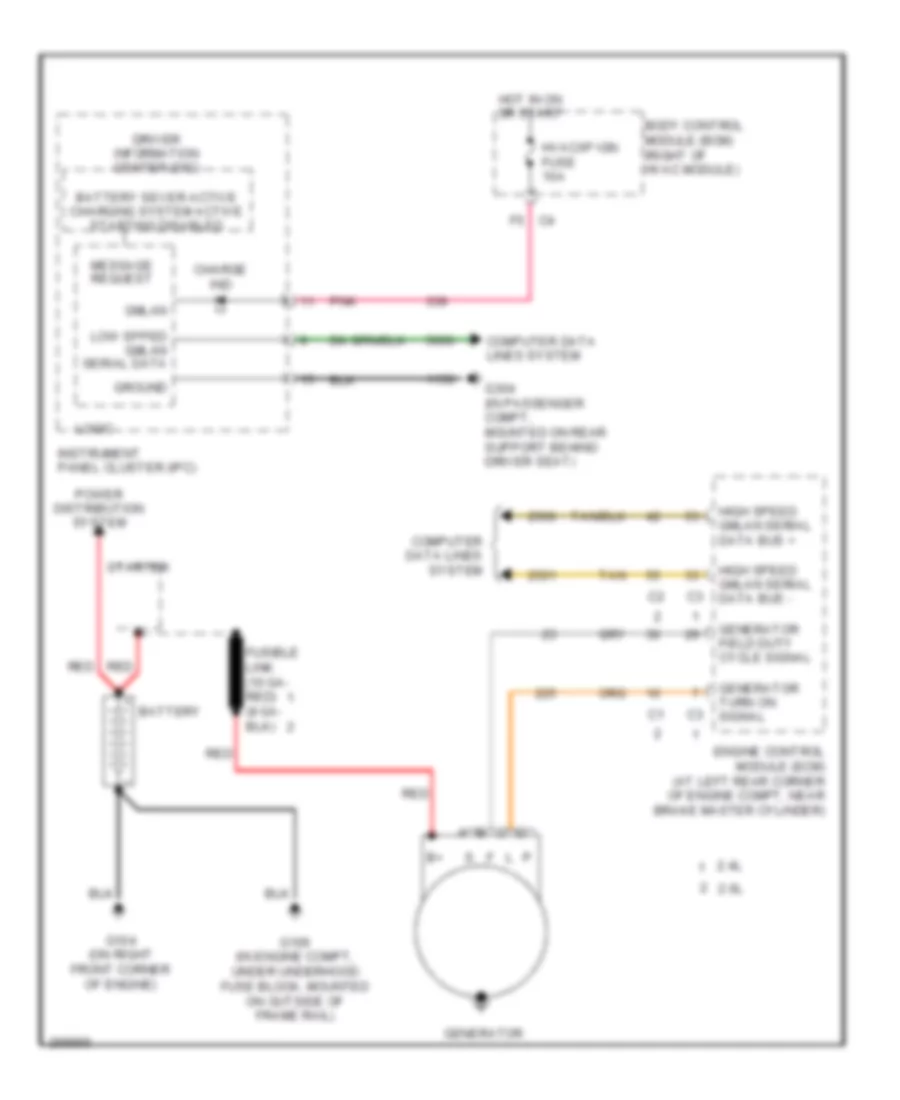
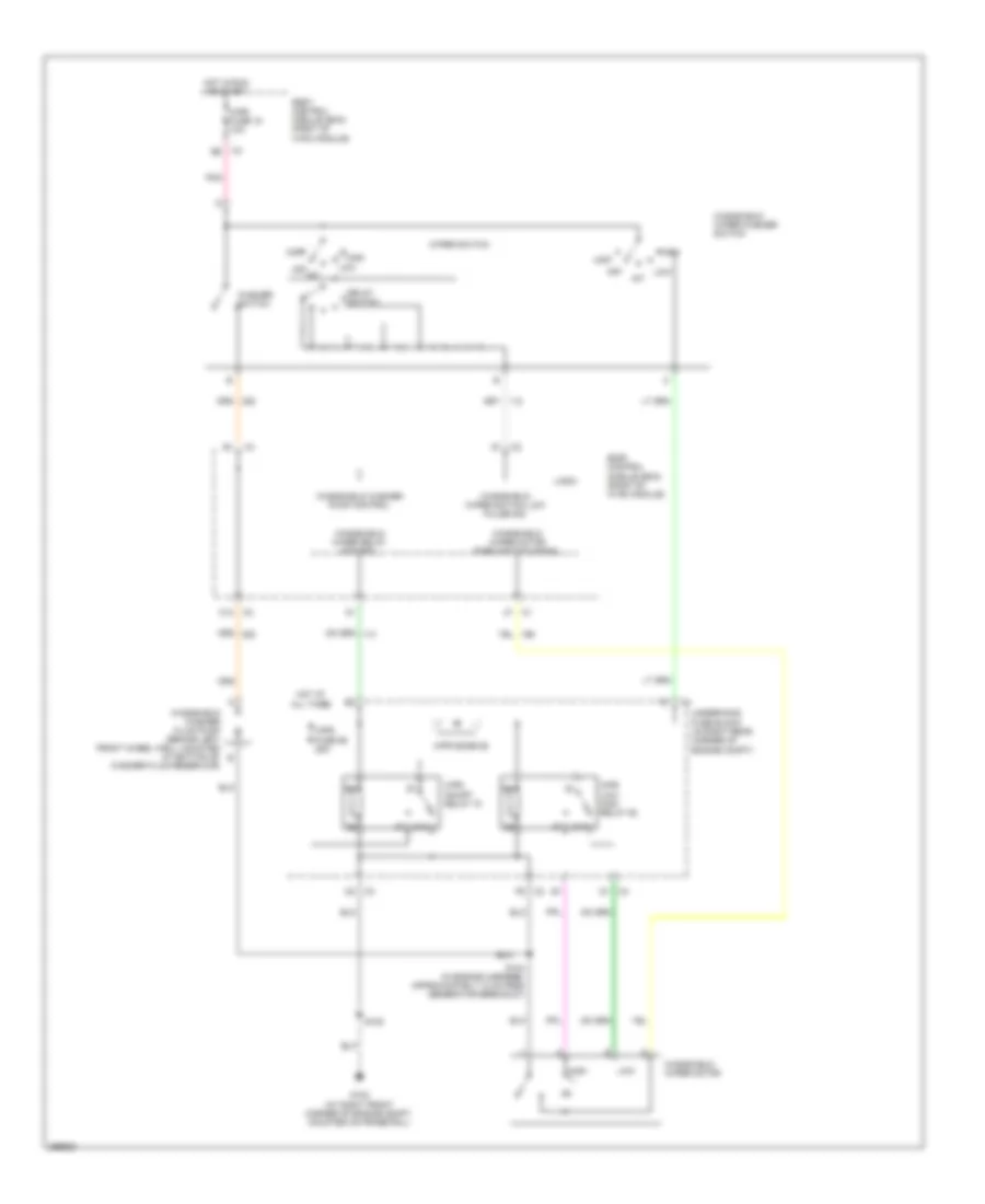
STARTING/CHARGING
Charging Wiring Diagram for Saturn Sky 2007
List of elements for Charging Wiring Diagram for Saturn Sky 2007:
- 2.0l
- 2.4l
- Battery
- Battery sever active charging system active starting disabled
- Body control module (bcm) (right of hvac module)
- Charge ind
- Computer data lines system
- Driver information center (dic)
- Engine control module (ecm) (at left rear corner of engine compt, near brake master cylinder)
- G104 (on right front corner of engine)
- G106 (in engine compt, under underhood fuse block, mounted on outside of frame rail)
- G304 (in passenger compt, mounted on rear support behind driver seat)
- Generator
- Generator field duty cycle signal
- Generator turn on signal
- Gmlan
- Ground
- High speed gmlan serial data bus +
- High speed gmlan serial data bus -
- Hot in on or start
- Hvac/ip ign fuse 10a
- Instrument panel cluster (ipc)
- Logic
- Low spped gmlan serial data
- Message request
- Pnk
- Power distribution system
- Red
- Starter
- Tan
Starting Wiring Diagram for Saturn Sky 2007
List of elements for Starting Wiring Diagram for Saturn Sky 2007:
- (in right rear corner of engine compt) underhood fuse block
- 2.0l
- 2.0l w/ m/t
- 2.4l
- 2.4l w/ m/t
- A/t
- B9 c2
- Battery
- Body control module (bcm) (right of hvac module)
- Charging circuit
- Clutch start neutral start
- Clutch start switch (mounted at top of clutch pedal bracket)
- Crnk fuse 30a
- Crnk relay
- Engine control module (ecm) (at left rear corner of engine compt, near brake master cylinder)
- Fusible link
- G104 (on right front corner of engine)
- G106 (in engine compt, under underhood fuse block, mounted on outside of frame rail)
- Hot w/ run/crank relay energized
- Hvac/ ip ign fuse 10a
- M/t
- Pnk
- Pnp/clutch start sw sig
- Red
- Starter
- Starter rly coil ctrl
SUPPLEMENTAL RESTRAINTS
Supplemental Restraints Wiring Diagram (1 of 2) for Saturn Sky 2007
List of elements for Supplemental Restraints Wiring Diagram (1 of 2) for Saturn Sky 2007:
- (in passenger compartment, (mounted on rear support behind driver's seat) g304
- (in seat belt buckle) passenger seat belt switch
- (in the passenger compt, behind the lower right trim panel)
- Air bag fuse 13 10a
- Air bag ind
- Battery positive vol
- Body control module (right of the hvac module)
- Clstr fuse 7 10a
- Driver seat belt switch (in seat belt buckle)
- Gmlan
- Gmlan serial data
- Ground
- High control
- Hot at all times
- Hot in run or start
- Hvac/ ip ign fuse 16 10a
- Ignition 1 voltage
- Inflatable restraint sensing & diagnostic module (sdm) (under passenger seat)
- Inflatable restraint steering wheel module (in steering wheel)
- Inflatable restraint steering wheel module coil (behind the steering wheel)
- Instrument panel cluster (ipc)
- Left inflatable restraint front end sensor (on left frame rail, attached to the back of the hinge bracket)
- Left seat belt pretensioner (in driver seat belt retractor)
- Left seat belt sw
- Logic
- Low control
- Low reference
- Low speed gmlan serial data
- Nca
- Passenger seat belt indicator control
- Pnk
- Right inflatable restraint front end sensor (on right frame rail, attached to the back of the hinge bracket)
- Right seat belt pretensioner (in passenger seat belt retractor)
- Right seat belt sw sig
- S205
- S300 (in the i/p body harness)
- Sdm fuse 24 10a
- Sensor serial data
- Sensor signal
- Sensor voltage
- Shorting bar
- Splice pack sp200
- Stage 1
- Stage 1 high control
- Stage 1 low control
- Stage 2
- Stage 2 high control
- Stage 2 low control
- Tan
Supplemental Restraints Wiring Diagram (2 of 2) for Saturn Sky 2007
List of elements for Supplemental Restraints Wiring Diagram (2 of 2) for Saturn Sky 2007:
- Airbag off sig
- Airbag on sig
- G300 (under center console)
- G304 (in passenger compartment, mounted on rear support behind driver's seat)
- Ground
- I/p mdl sw sig
- Ign 1 voltage
- Ind ctrl
- Inflatable restraint i/p module (under passenger side of dash)
- Inflatable restraint passenger air bag on/off indicator
- Inflatable restraint passenger presence system (pps) module (under passenger seat)
- Inflatable restraint passenger presence system (pps) sensor (under passenger seat)
- Mass & pos sig
- Nca
- Off
- Pass air bag ind
- Pass seat belt ind
- Pnk
- S301
- Sens serial data
- Shorting bar
- Stage 1
- Stage 2
TRANSMISSION
A/T Wiring Diagram for Saturn Sky 2007
List of elements for A/T Wiring Diagram for Saturn Sky 2007:
- (2.0l)
- (2.4l)
- (at left rear corner of engine compt, near brake master cylinder) engine control module (ecm)
- (in engine harness, approximately 5 cm from brake fluid level switch breakout)
- (or red)
- 1-2 shift solenoid valve
- 2-3 shift solenoid valve
- 4-5 shift solenoid valve
- A/t iss high sig
- A/t iss low sig
- A12
- Acc volt
- All times
- Automatic transmission
- B11
- Battery
- Body control module (right of hvac module)
- Clutch pres ctrl
- Computer data lines system
- Ecm/ trans fuse 43 15a
- Ecm/tcm fuse 25 10a
- Exterior lights system
- F10
- F11
- F12
- F13
- F14
- F15
- F16
- F17
- F18
- F19
- F20
- F21
- F22
- F23
- F24
- F25
- F26
- F27
- F28
- F29
- F30
- F31
- F32
- F33
- F34
- F35
- F36
- F37
- F38
- G104 (on right front corner of engine)
- Gmlan ser data+
- Gmlan ser data-
- Ground
- Hot at
- Hot in run
- Ign 1 volt
- Input speed sensor
- Internal mode switch (ims)
- Logic
- Low ref
- Or start
- Oss high sig
- Oss low sig
- Output speed sensor
- Pc sol
- Pc sol valve ctrl
- Pnk
- Pressure control (pcs) solenoid valve
- Prk/neut sig
- Red
- S108
- S118
- S206 (in i/p body harness, approximately 13.5 cm from body control module)
- S216 (in i/p body harness, approximately 7 cm from accelerator pedal position sensor breakout)
- Shift sol valve
- Solstice
- Stop lmp sply
- Tan
- Tcc sol
- Tft sensor sig
- Torque converter clutch (tcc) (pwm) solenoid valve
- Tr sw a
- Tr sw b
- Tr sw c
- Tr sw p
- Transmission control module (tcm) (near brake master cylinder)
- Transmission fluid temperature (tft) sensor
- Underhood fuse block (in right rear corner of engine compt)
TRUNK, TAILGATE, FUEL DOOR
Trunk Release Wiring Diagram for Saturn Sky 2007
List of elements for Trunk Release Wiring Diagram for Saturn Sky 2007:
- (at base of rear window) folding top cover actuator
- (in i/p body harness, approximately 74 cm from g301 breakout) s214
- (sky)
- (solstice)
- (under center console) g300
- Ajar sw sig
- Body control module (right of hvac module)
- Driver information center (dic) message center
- F3 c2
- G301 (on left "b" pillar)
- Gmlan serial data
- Gnd
- Hot at all times
- Ign
- Instrument panel cluster (ipc)
- Logic
- Low spd gmlan serial data
- Message request
- Nca
- Radio (sky)
- Radio chime
- Rear ajar ind (sky)
- Rear compartment lid ajar switch (below rear window)
- Rear compartment lid release actuator (base of convertible top)
- Rear compartment lid release switch
- Rear compt lid relse sw
- Rly ctrl
- S207 s301 (sky)
- S311 (solstice)
- S400 (sky)
- Serial data
- Solstice
- Splice pack sp200 (in passenger compt, behind lower right trim panel)
- Tan
- Trunk ajar
- Trunk fuse 10 25a
- Trunk fuse 11 5a
- Trunk relse relay
- Underhood fuse block (in right rear corner of engine compt)
WARNING SYSTEMS
Warning Systems Wiring Diagram for Saturn Sky 2007
List of elements for Warning Systems Wiring Diagram for Saturn Sky 2007:
- (in i/p body harness, approximately 31 cm from g300 breakout) s300
- (under center console) g300
- 5v ref
- Acc
- Auto
- Body control module (bcm) (right of hvac module)
- Chime
- Computer data lines system
- Dr lck fuse 26 15a
- Driver door lock actuator (inside center rear of left door)
- Driver seat belt switch (in seat belt buckle)
- G300 (under center console)
- Ground
- Head
- Hot at all times
- Hot in run or start
- Hvac/ ip ign fuse 16 10a
- Ign
- Ignition switch
- Inflatable restraint passenger air bag on/off indicator
- Inflatable restraint sensing & diagnostic module (sdm) (under passenger seat)
- Instrument panel cluster (ipc)
- Key-in ignition switch
- Left seat belt sw
- Lf door ajar sw
- Logic
- Low ref
- Low spd gmlan serial data
- Low spd serial data
- Nca
- Off
- Off run/crank voltage
- Park
- Park lmp sw sig
- Pass seat belt ind sig
- Passenger seat belt switch (in seat belt buckle)
- Pnk
- Radio
- Right seat belt sw
- Run
- S301
- S500
- Seat belt ind
- Start
- Turn signal/ multi- function switch
WIPER/WASHER
Wiper/Washer Wiring Diagram for Saturn Sky 2007
List of elements for Wiper/Washer Wiring Diagram for Saturn Sky 2007:
- 87a
- Body control module (bcm) (right of hvac module)
- C12 c3
- C5 c3
- D1 c4
- Delay switch
- F9 c2
- G102 (at right front corner of engine compt, mounted on frame rail)
- High
- Hot at all times
- Hot in run or start
- Int
- Logic
- Low
- Mist
- Off
- Pnk
- S104 (in engine harness, approximately 12 cm from generator breakout)
- S105
- Underhood fuse block (in right rear corner of engine compt)
- Washer switch
- Windshield washer fluid pump (behind left front wheel well, mounted at bottom of washer fluid reservoir)
- Windshield washer pump control
- Windshield wiper motor
- Windshield wiper motor park switch signal
- Windshield wiper relay control
- Windshield wiper switch low pulse sig
- Windshield wiper/washer switch
- Wiper switch
- Wpr diode 58
- Wpr fuse 15 10a
- Wpr fuse 59 25a
- Wpr low/ high relay 52
- Wpr on/off relay 70

 Čeština
 Dansk
Dansk Deutsch
 Ελληνικά
 English
 English
 Español
 Suomi
Suomi Français
 Français
 עברית
עברית Hrvatski
 Magyar
 Italiano
 日本語
日本語 한국어
한국어 Nederlands
 Polski
 Português
 Português
 Русский
 Slovenčina
 Slovenščina
 Svenska
 Türkçe
 中文 (中国)