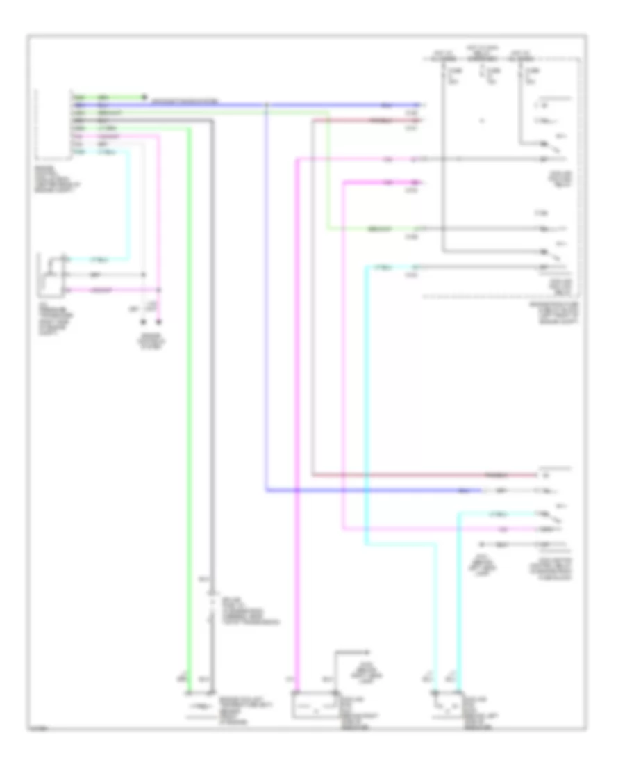
AIR CONDITIONING
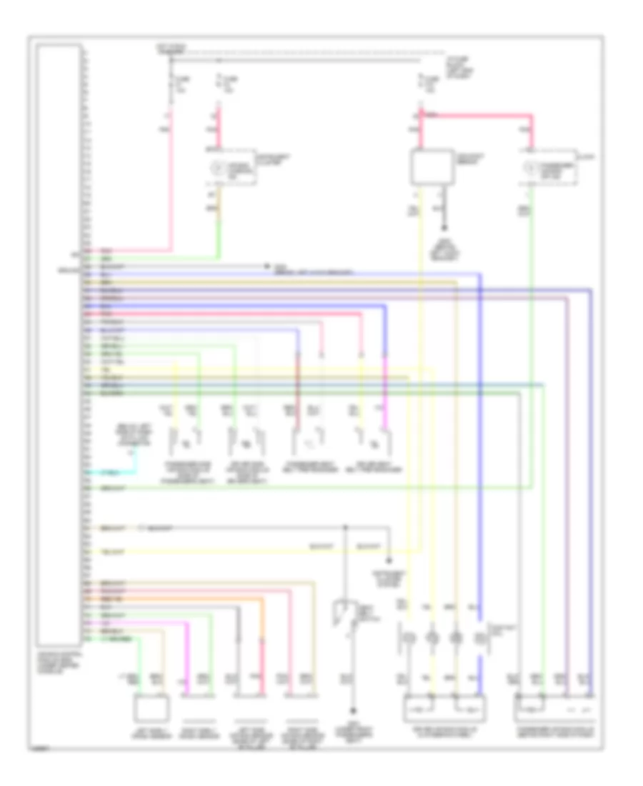
Manual A/C Wiring Diagram (1 of 2) for Suzuki Reno 2006
 https://portal-diagnostov.com/license.html
Automotive Electricians Portal FZCO
Automotive Electricians Portal FZCO
https://portal-diagnostov.com/license.html
https://portal-diagnostov.com/license.html
Automotive Electricians Portal FZCO
Automotive Electricians Portal FZCO
List of elements for Manual A/C Wiring Diagram (1 of 2) for Suzuki Reno 2006:
- (behind right head lamp) g102
- A/c compressor
- A/c compressor relay
- A/c control switch
- A/c pressure transducer (right side of engine compt)
- A/c switch
- A10
- Blower motor (behind right side of dash)
- Blower motor resistor (behind right side of dash, near blower motor)
- Blower motor switch
- Blower relay
- C101
- C104
- C105
- C106
- C201
- C25
- C30
- C35
- C50
- E25
- E34
- E51
- Engine control module (ecm) (center rear of engine compt)
- Engine controls system
- Engine coolant temperature (ect) sensor (front of engine)
- Engine room fuse & relay block (left front of engine compt)
- Fuse 10a
- Fuse 15a
- Fuse 20a
- Fuse 30a
- G201 (left side of dash)
- G203 (behind left audio bracket)
- Hot at all times
- Hot in on
- Hot in on or start
- I/p fuse block (left end of dash)
- Illumination
- Intake motor
- Interior lights system
- Off
- Pnk
- Red
- Splice pack 101 (in engine room harness, near top of transmission)
- Splice pack 203 (behind center of dash)
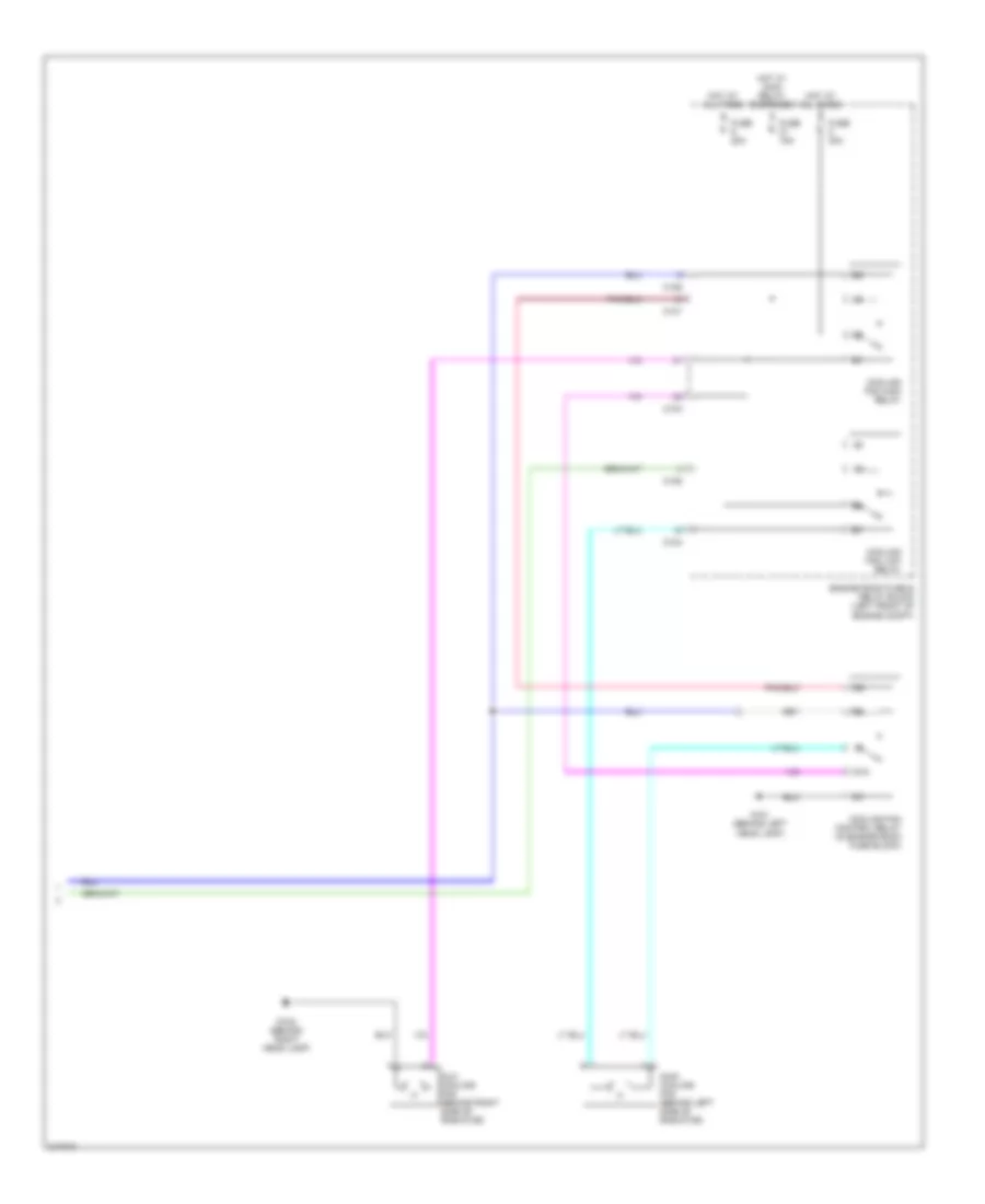
Manual A/C Wiring Diagram (2 of 2) for Suzuki Reno 2006
List of elements for Manual A/C Wiring Diagram (2 of 2) for Suzuki Reno 2006:
- 87a
- Aux cooling fan (behind right side of radiator)
- C101
- C104
- C106
- Cooling fan control relay (in engine room fuse block)
- Cooling fan high relay
- Cooling fan low relay
- Engine room fuse & relay block (left front of engine compt)
- Fuse 15a
- Fuse 20a
- Fuse 30a
- G101 (behind left head lamp)
- G102 (behind right head lamp)
- Hot at all times
- Hot w/ main relay energized
- Main cooling fan (behind left side of radiator)
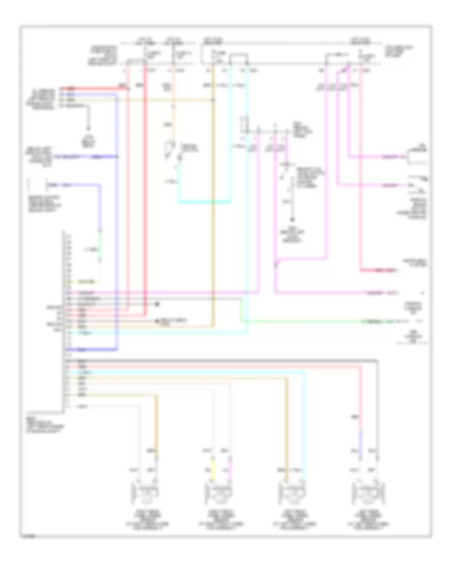
ANTI-LOCK BRAKES
Anti-lock Brakes Wiring Diagram for Suzuki Reno 2006
List of elements for Anti-lock Brakes Wiring Diagram for Suzuki Reno 2006:
- (below ebcm) g106
- (below left side of dash) data link
- A13
- A19
- Abs
- Brake fluid level switch (on brake master cylinder)
- Brake switch
- C102
- C107
- C201
- C64
- Connector (dlc)
- Drl module
- Ebcm (abs module) (left rear corner of engine compt)
- Engine control module (ecm) (center rear of engine compt)
- Engine room fuse & relay block (left front of engine compt)
- Fuse 10a
- Fuse 13 15a
- Fuse 2 60a
- Fuse 4 10a
- G106 (below ebcm)
- G204 (behind left audio bracket)
- Ground
- Hot at all times
- Hot in on or start
- I/p fuse block (left end of dash)
- Ign+
- Instrument cluster
- Left front wheel speed sensor (at left front wheel hub assembly)
- Left rear wheel speed sensor (at left rear wheel hub assembly)
- Oil feeding connector (left rear of engine compt, near ecbm)
- Parking
- Parking brake switch (under center console)
- Pnk
- Red
- Right front wheel speed sensor (at right front wheel hub assembly)
- Right rear wheel speed sensor (at right rear wheel hub assembly)
- S301 (behind left kick panel)
- Warning ind
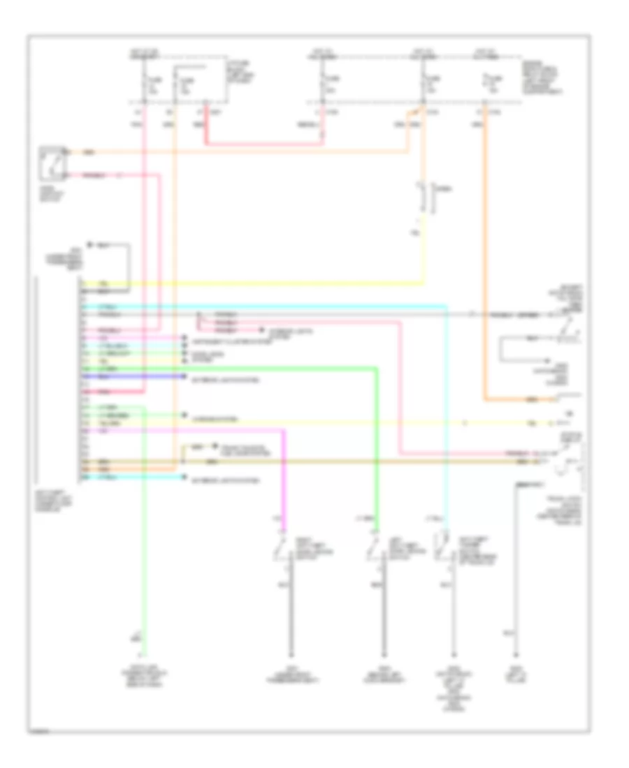
ANTI-THEFT
Anti-theft Wiring Diagram for Suzuki Reno 2006
List of elements for Anti-theft Wiring Diagram for Suzuki Reno 2006:
- (except notch back) tail gate open switch
- (left "c" pillar) g402 (hatchback) g304 (wagon)
- (or red)
- Anti-theft control unit (under floor console)
- Anti-theft tamper switch (center rear of trunk lid)
- C102
- C104
- C105
- C201
- Data link connector (dlc) (below left side of dash)
- Door locks system
- Engine room fuse & relay block (left front of engine compartment)
- Exterior lights system
- Fuse 10a
- Fuse 15a
- Fuse 30a
- G204 (behind left audio bracket)
- G301 (under front passenger's seat)
- G302 (left "c" pillar)
- G302 (notch back)
- G402 (hatchback) g304 (wagon)
- Hood contact switch
- Hot at all times
- Hot at on or start
- I/p fuse block (left end of dash)
- Instrument cluster system
- Interior lights system
- Left anti-theft door locking switch
- Pnk
- Red
- Right anti-theft door locking switch
- Siren
- Status display
- Trunk latch switch (notch back) (center rear of trunk lid)
- Trunk,tailgate, fuel door system
- Warning system
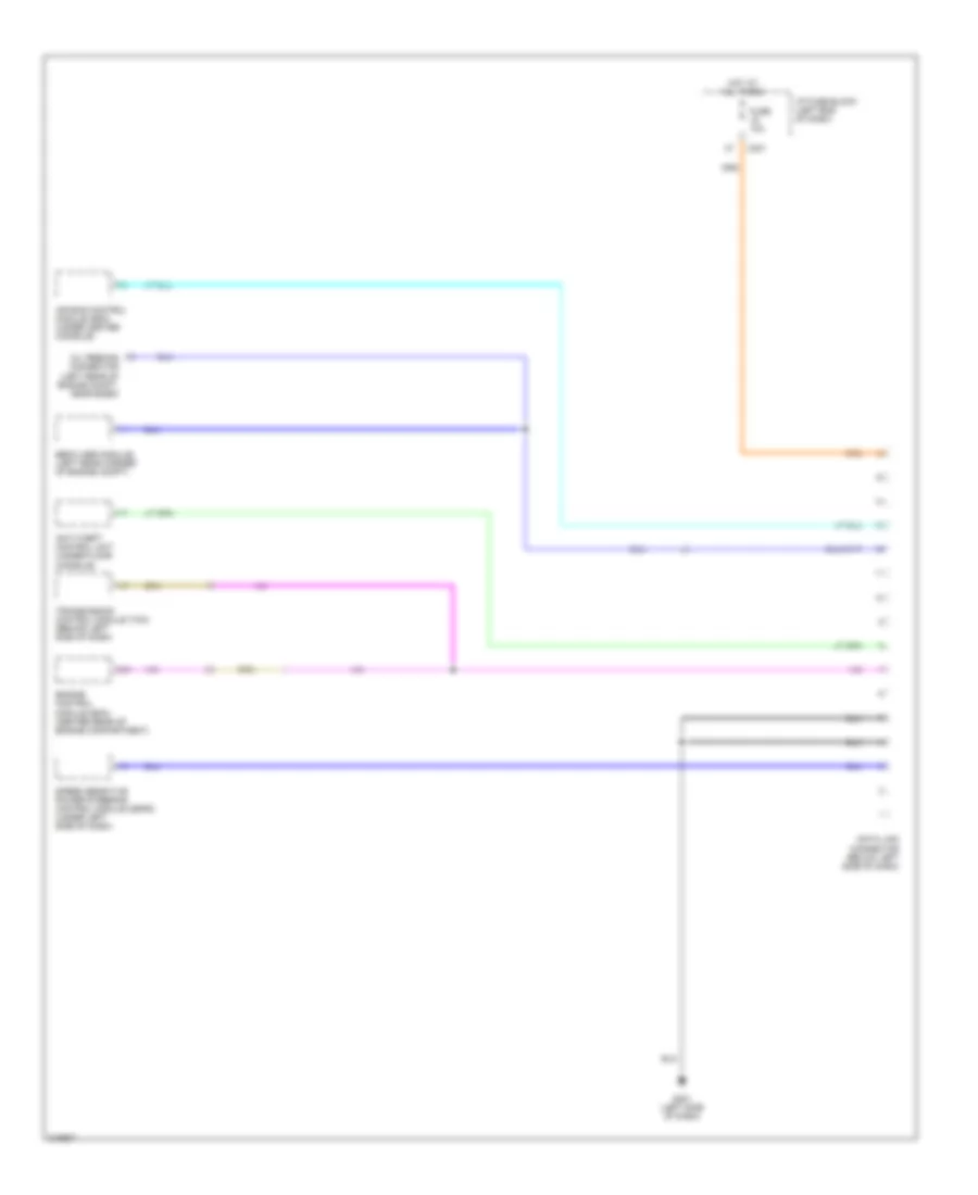
COMPUTER DATA LINES
Computer Data Lines Wiring Diagram for Suzuki Reno 2006
List of elements for Computer Data Lines Wiring Diagram for Suzuki Reno 2006:
- Air bag control module (sdm) (under center console)
- Anti-theft control unit (under floor console)
- C201
- C31
- Data link connector (below left side of dash)
- Ebcm (abs module) (left rear corner of engine compt)
- Engine control module (ecm) (center rear of engine compartment)
- Fuse 10a
- G201 (left side of dash)
- Hot at all times
- I/p fuse block (left end of dash)
- Oil feeding connector (left rear of engine compt, near ecbm)
- Speed sensitive power steering control module (ssps) (under left side of dash)
- Transmission control module (tcm) (behind left side of dash)
COOLING FAN
Cooling Fan Wiring Diagram for Suzuki Reno 2006
List of elements for Cooling Fan Wiring Diagram for Suzuki Reno 2006:
- 87a
- A/c pressure transducer (right side of engine compt)
- Air conditioning system
- C101
- C104
- C106
- C30
- C35
- C50
- Cooling fan aux (behind right side of radiator)
- Cooling fan control relay (in engine room fuse block)
- Cooling fan high relay
- Cooling fan low relay
- Cooling fan main (behind left side of radiator)
- E25
- E34
- E51
- Engine control module (ecm) (center rear of engine compt)
- Engine controls system
- Engine coolant temperature (ect) sensor (front of engine)
- Engine room fuse & relay block (left front of engine compt)
- Fuse 15a
- Fuse 20a
- Fuse 30a
- G101 (behind left head lamp)
- G102 (behind right head lamp)
- Hot at all times
- Hot w/ main relay energized
- Splice pack 101 (in engine room harness, near top of transmission)
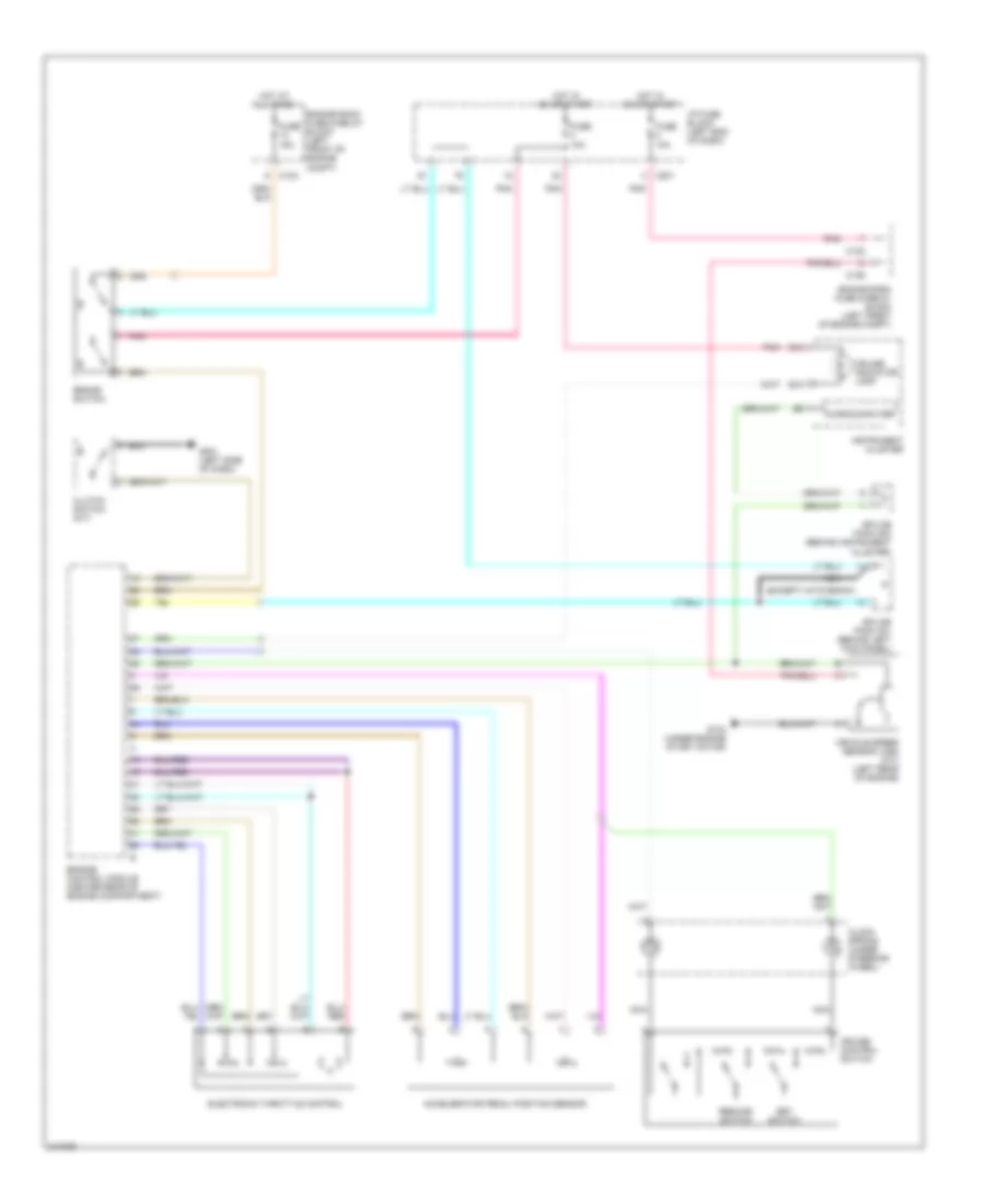
CRUISE CONTROL
Cruise Control Wiring Diagram for Suzuki Reno 2006
List of elements for Cruise Control Wiring Diagram for Suzuki Reno 2006:
- (except hatchback)
- Accelerator pedal position sensor
- B10
- B15
- Brake switch
- C102
- C106
- C201
- Clock spring (under steering wheel)
- Clutch switch (m/t)
- Cruise control switch
- Cruise indicator lamp
- Electronic throttle control
- Engine control module (center rear of engine compartment)
- Engine room fuse & relay block (left front of engine compt)
- Fuse 10a
- Fuse 15a
- G104 (under engine start motor)
- G201 (left side of dash)
- Hot at all times
- Hot in on or start
- I/p fuse block (left end of dash)
- Instrument cluster
- Microcomputer
- Nca
- Pnk
- Resume switch
- Set switch
- Splice pack 202 (behind instrument cluster)
- Splice pack 301 (behind left kick panel)
- Vehicle speed sensor (vss) (m/t) (left rear of engine)
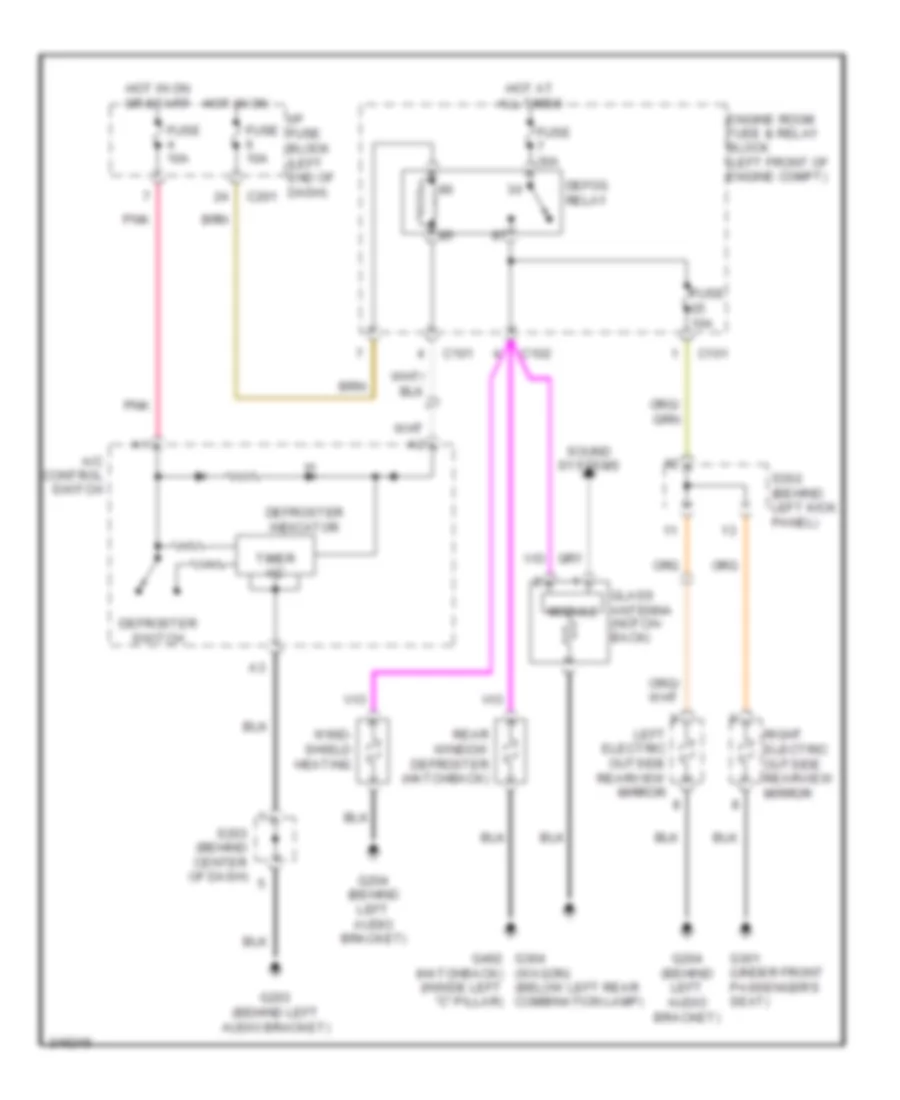
DEFOGGERS
Defoggers Wiring Diagram for Suzuki Reno 2006
List of elements for Defoggers Wiring Diagram for Suzuki Reno 2006:
- (wagon) (below left rear combination lamp)
- A/c control switch
- C101
- C102
- Defog relay
- Defroster indicator
- Defroster switch
- Engine room fuse & relay block (left front of engine compt)
- Fuse 10a
- Fuse 30a
- G203 (behind left audio bracket)
- G204 (behind left audio bracket)
- G301 (under front passenger's seat)
- G304 g402 (hatchback) (inside left "c" pillar)
- Glass antenna (notch- back)
- Hot at all times
- Hot in on
- Hot in on or start
- I/p fuse block (left end of dash) c201
- Left electric outside rearview mirror
- Module
- Pnk
- Rear window defroster (hatchback)
- Right electric outside rearview mirror
- S203 (behind center of dash)
- S302 (behind left kick panel)
- Sound systems
- Timer i/c
- Wind- shield heating
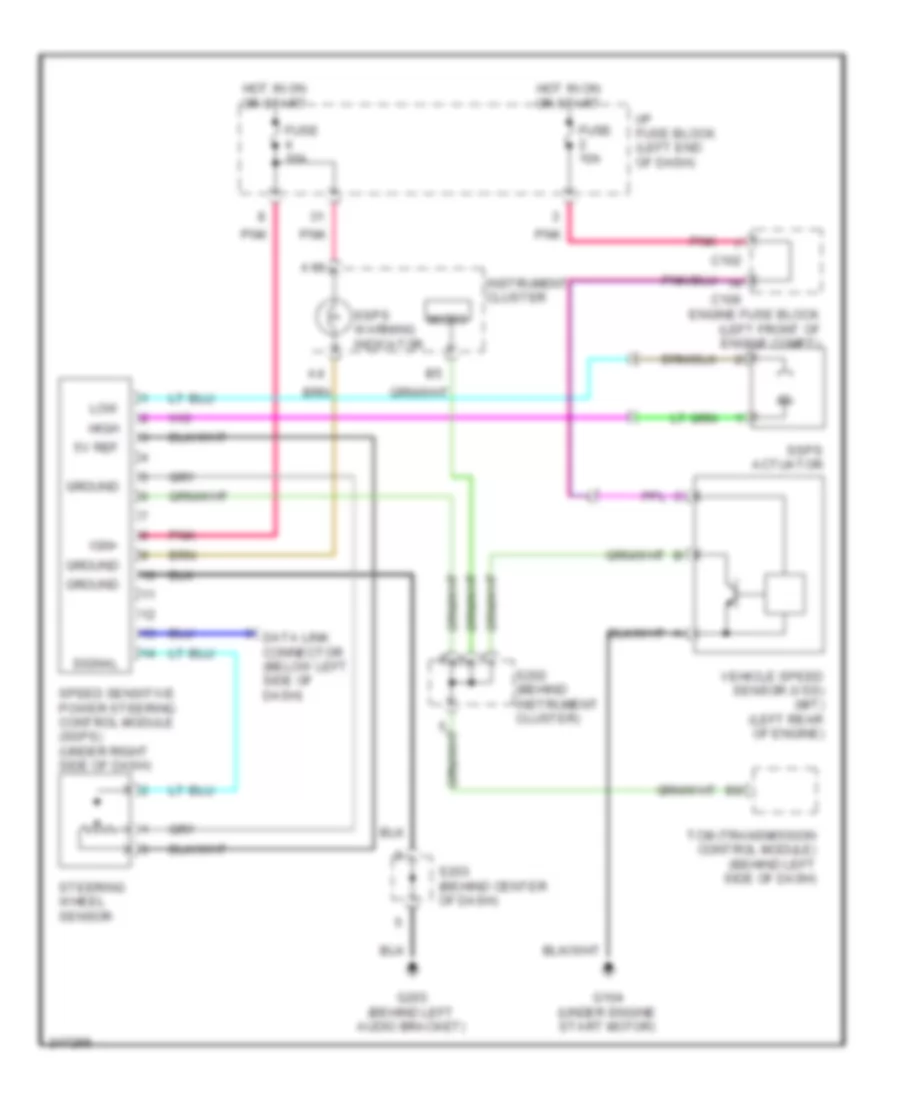
ELECTRONIC POWER STEERING
Electronic Power Steering Wiring Diagram for Suzuki Reno 2006
List of elements for Electronic Power Steering Wiring Diagram for Suzuki Reno 2006:
- 5v ref
- A19
- C102
- C106
- Data link connector (below left side of dash)
- Engine fuse block (left front of engine compt)
- Fuse 10a
- G104 (under engine start motor)
- G203 (behind left audio bracket)
- Ground
- High
- Hot in on or start
- I/p fuse block (left end of dash)
- Ign+
- Instrument cluster
- Low
- Micro
- Pnk
- S202 (behind instrument cluster)
- S203 (behind center of dash)
- Signal
- Speed sensitive power steering control module (ssps) (under right side of dash)
- Ssps actuator
- Ssps warning indicator
- Steering wheel sensor
- Tcm (transmission control module) (behind left side of dash)
- Vehicle speed sensor (vss) (m/t) (left rear of engine)
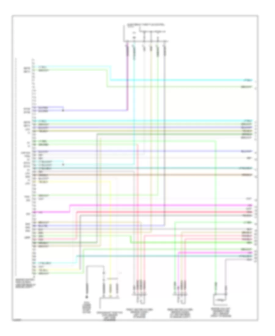
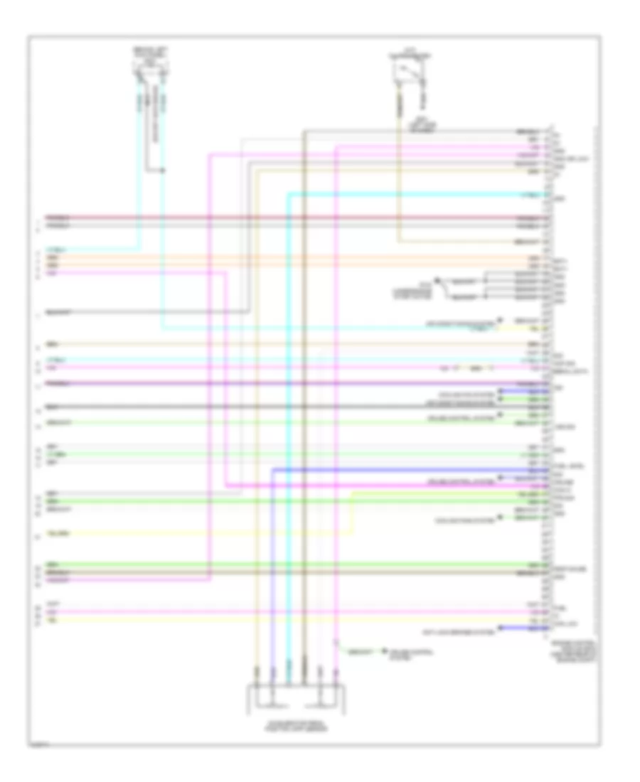
ENGINE PERFORMANCE
2.0L
2.0L, Engine Performance Wiring Diagram (1 of 5) for Suzuki Reno 2006
List of elements for 2.0L, Engine Performance Wiring Diagram (1 of 5) for Suzuki Reno 2006:
- Crankshaft position (ckp) sensor (left side of engine)
- Electronic throttle control
- Engine control module (ecm) (center rear of engine compt)
- Engine coolant temperature (ect) sensor (front of engine)
- Esta
- Estb
- Etca
- Etcb
- Front heated oxygen sensor (ho2s1) (left side of engine)
- G104 (under engine start motor)
- Gnd
- Legr
- Low
- Map sig
- Pnk
- Rear heated oxygen sensor (ho2s2) (at center rear of engine compt)
- Sig
- Tps1
- Tps2
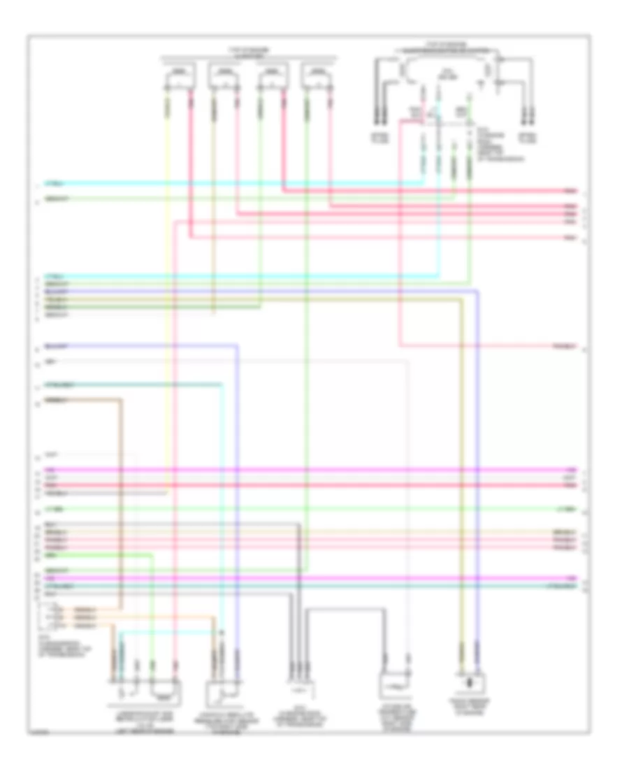
2.0L, Engine Performance Wiring Diagram (2 of 5) for Suzuki Reno 2006
List of elements for 2.0L, Engine Performance Wiring Diagram (2 of 5) for Suzuki Reno 2006:
- (top of engine)
- (top of engine) injectors
- Coil driver
- Electronic ignition (ei) system
- Intake air temperature (iat) sensor (right side of engine)
- Knock sensor (right rear of engine)
- Linear exhaust gas recirculation (legr) valve (left rear of engine)
- Manifold absolute pressure (map) sensor (top right side of engine)
- Nca
- Pnk
- S101 (in engine room harness, near top of transmission)
- Spark plugs
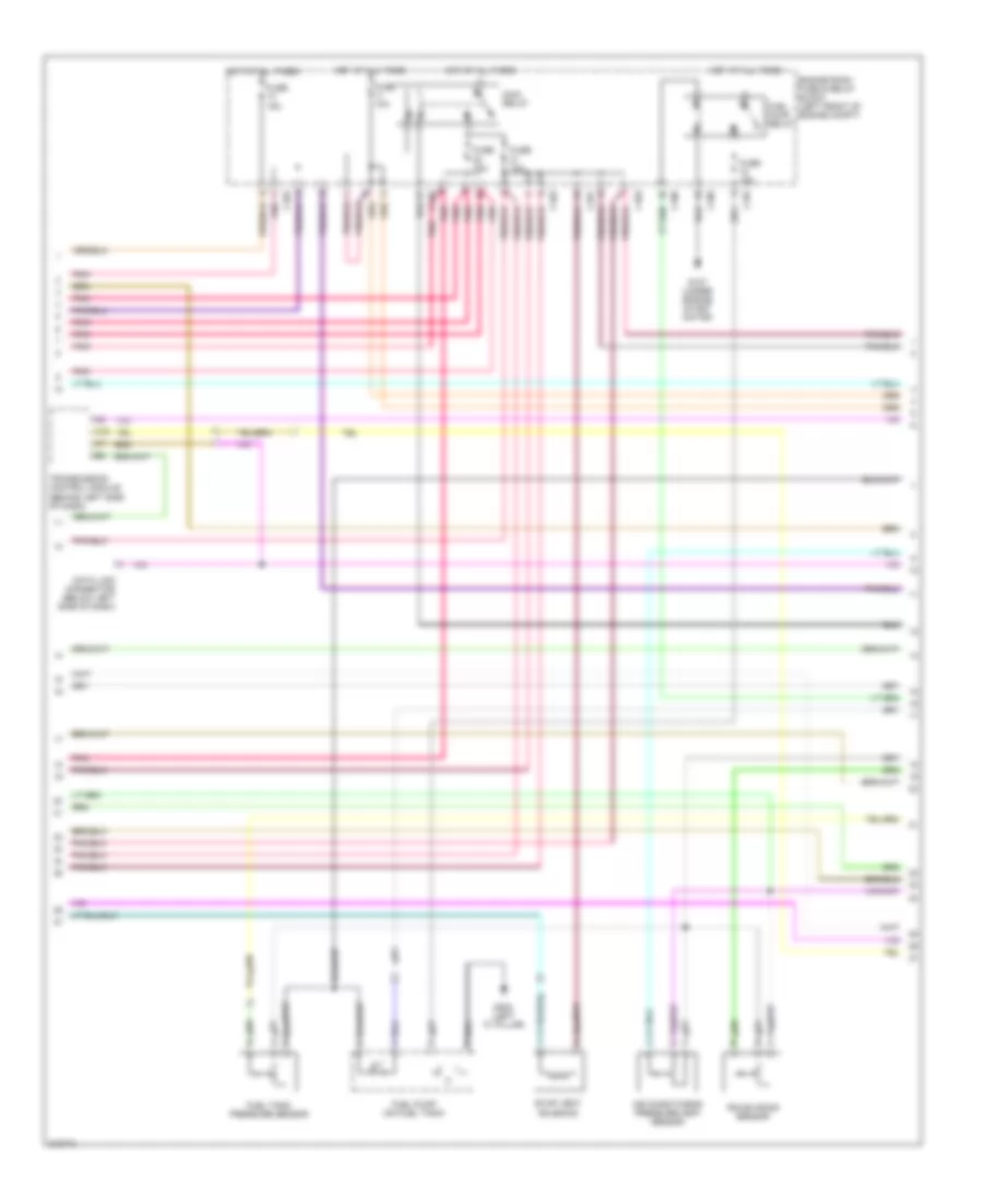
2.0L, Engine Performance Wiring Diagram (3 of 5) for Suzuki Reno 2006
List of elements for 2.0L, Engine Performance Wiring Diagram (3 of 5) for Suzuki Reno 2006:
- (behind instrument cluster) s202
- A18
- A19
- B15
- Brake switch
- C102
- C201
- C202
- Camshaft position (cmp) sensor (front of engine)
- Engine room fuse & relay block (left front of eng compt)
- Evap canister purge solenoid
- Fuse 10a
- Fuse 15a
- G104 (under engine start motor)
- G201 (left side of dash)
- Hot at all times
- Hot in on or start
- I/p fuse block (left end of dash)
- Instrument cluster
- Malfunction indicator lamp (mil) ind
- Micom
- Pnk
- Speedo- meter
- Tacho- meter
- Vehicle speed sensor (vss) (m/t) (left rear of engine)
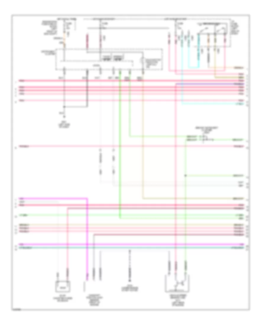
2.0L, Engine Performance Wiring Diagram (4 of 5) for Suzuki Reno 2006
List of elements for 2.0L, Engine Performance Wiring Diagram (4 of 5) for Suzuki Reno 2006:
- A16
- Air conditioning pressure (acp) sensor
- C101
- C102
- C103
- C106
- Data link connector (below left side of dash)
- Engine room fuse & relay block (left front of engine compt)
- Evap vent solenoid
- Fuel pump (on fuel tank)
- Fuel pump relay
- Fuel tank pressure sensor
- Fuse 10a
- Fuse 15a
- G107 (under engine start motor)
- G302 (left "c" pillar)
- Hot at all times
- Main relay
- Pnk
- Rough road sensor
- Transmission control module (behind left side of dash)
2.0L, Engine Performance Wiring Diagram (5 of 5) for Suzuki Reno 2006
List of elements for 2.0L, Engine Performance Wiring Diagram (5 of 5) for Suzuki Reno 2006:
- (behind left kick panel) s301
- (except hatchback)
- (m/t) clutch switch
- Accelerator pedal position (app) sensor
- Acp sig
- Air conditioning system
- Anti-lock brakes system
- Bat+
- Can hi
- Can low
- Cooling fan system
- Cooling fans system
- Cruise
- Cruise control system
- Engine control module (ecm) (center rear of engine compt)
- Fps sig
- Fuel
- Fuel level
- G104 (under engine start motor)
- G201 (left side of dash)
- Gnd
- Gnd (or low)
- Ign
- Nca
- Rpm
- Serial data
- Sig
- Temp gauge
- Vss sig
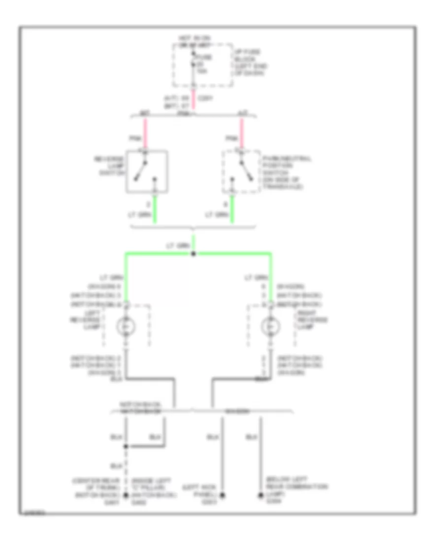
EXTERIOR LIGHTS
Back-up Lamps Wiring Diagram for Suzuki Reno 2006
List of elements for Back-up Lamps Wiring Diagram for Suzuki Reno 2006:
- (a/t) (m/t)
- (below left rear combination lamp) g304
- (center rear of trunk) (notch back) g401
- (hatch back)
- (inside left "c" pillar) (hatch back) g402
- (left kick panel) g303
- (notch back)
- (notch back) (hatch back) (wagon)
- (wagon)
- A/t
- C201
- Fuse 10a
- Hot in on or start
- I/p fuse block (left end of dash)
- Left reverse lamp
- M/t
- Notch back, hatch back
- Park/neutral position switch (on side of transaxle)
- Pnk
- Reverse lamp switch
- Right reverse lamp
- Wagon
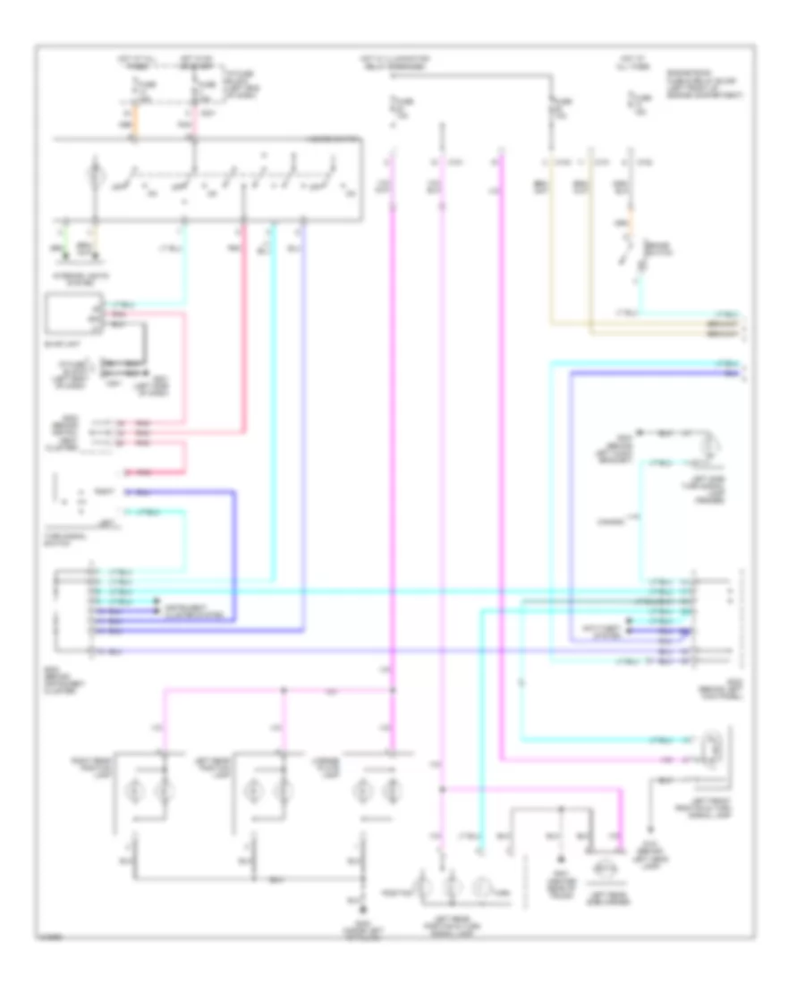
Exterior Lamps Wiring Diagram (1 of 2) for Suzuki Reno 2006
List of elements for Exterior Lamps Wiring Diagram (1 of 2) for Suzuki Reno 2006:
- 49a
- Anti-theft system
- Blink unit
- Brake switch
- C101
- C102
- C104
- C201
- Canada
- Engine room fuse & relay block (left front of engine compartment)
- Fuse 10a
- Fuse 15a
- G101 (behind left head lamp)
- G201 (left side of dash)
- G204 (behind left audio bracket)
- G401 (center rear of trunk)
- G402 (inside left "c" pillar)
- Hazard switch
- Hot at all times
- Hot in on or start
- Hot w/ illumination relay energized
- I/p fuse block (left end of dash)
- Instrument cluster system
- Interior lights system
- Left
- Left front position & turn signal lamp
- Left rear position & turn signal lamp
- Left rear position lamp
- Left rear side marker
- Left side turn signal lamp (fender)
- License plate lamp
- Off
- Pnk
- Position
- Right
- Right rear position lamp
- S202 (behind instru- ment cluster)
- S202 (behind instrument cluster)
- S302 (behind left kick panel)
- Turn
- Turn signal switch
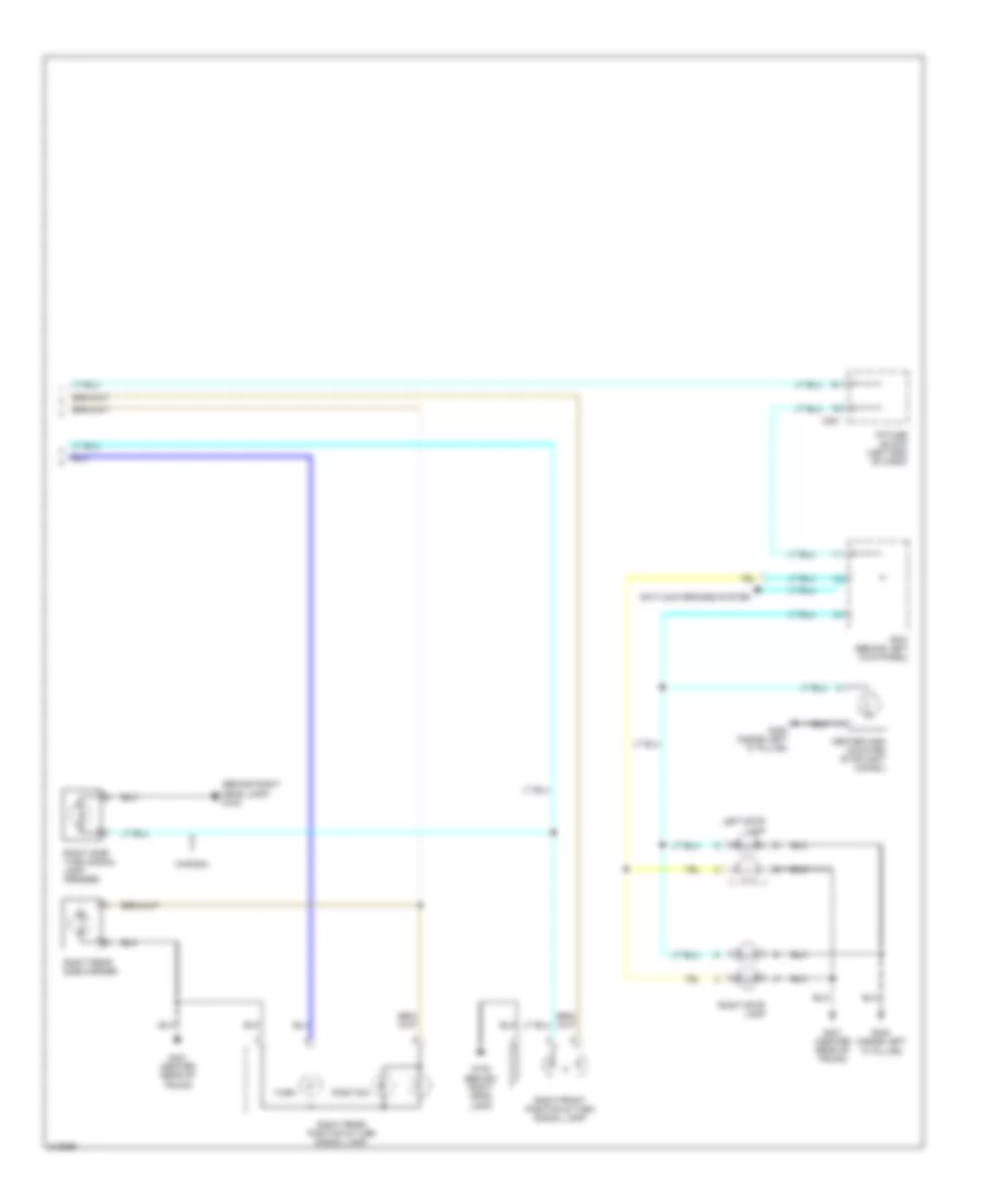
Exterior Lamps Wiring Diagram (2 of 2) for Suzuki Reno 2006
List of elements for Exterior Lamps Wiring Diagram (2 of 2) for Suzuki Reno 2006:
- (behind right head lamp) g102
- Anti-lock brakes system
- C201
- Canada
- Center high mounted stoplight (chmsl)
- G102 (behind right head lamp)
- G401 (center rear of trunk)
- G402 (inside left "c" pillar)
- I/p fuse block (left end of dash)
- Left stop lamp
- Position
- Right front position & turn signal lamp
- Right rear position & turn signal lamp
- Right rear side marker
- Right side turn signal lamp (fender)
- Right stop lamp
- S301 (behind left kick panel)
- Turn
GROUND DISTRIBUTION
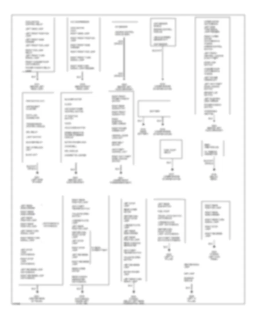
Ground Distribution Wiring Diagram for Suzuki Reno 2006
List of elements for Ground Distribution Wiring Diagram for Suzuki Reno 2006:
- "p" position switch
- (hatchback)
- (notchback & hatchback)
- (notchback)
- A/c compressor
- Air bag control module (sdm)
- Air conditioner control switch
- Anti-theft control unit
- Anti-theft temper switch
- Audio
- Battery
- Blink unit
- Blower motor
- Blower relay
- Brake fluid switch
- Center high mount stop lamp
- Center room lamp
- Central door lock unit
- Chime bell
- Cigarette lighter
- Ckp sensor shield
- Clock
- Cmp sensor
- Cooling fan (aux)
- Cooling fan control relay
- Data link connector
- Door lock switch
- Drl module
- Drl relay
- Ebcm (abs module)
- Engine control module
- Extra power jack
- Front fog lamp relay
- Front washer pump (notchback)
- Front wiper motor (hatchback & wagon)
- Fuel pump
- Fuel pump relay
- G101 (behind left head lamp)
- G102 (behind right head lamp)
- G103 (near battery)
- G104 (under engine starter motor)
- G105 (under engine starter motor)
- G106 (below ebcm)
- G107 (under engine starter motor)
- G201 (left side of dash)
- G202 (behind left audio bracket)
- G203 (behind left audio bracket)
- G204 (behind left audio bracket)
- G205 (left "a" pillar)
- G301 (under front passenger's seat)
- G302 (left "c" pillar)
- G303 (wagon) (left kick panel)
- G304 (wagon) (below left rear combination lamp)
- G401 (center rear of trunk)
- G402 (hatchback) (inside left "c" pillar)
- Hold mode switch
- Horn
- Instrument cluster
- Key interlock unit
- Left anti-theft door locking switch
- Left electric osrv mirror
- Left front central locking & anti-theft
- Left front fog lamp
- Left front position lamp
- Left front side marker
- Left front turn signal lamp
- Left head lamp
- Left power mirror unit
- Left rear position lamp
- Left rear side marker
- Left rear sub switch
- Left rear turn signal lamp
- Left reverse lamp
- Left reverse lamp (notchback)
- Left side turn signal lamp (fender)
- Left stop lamp
- Left stop lamp (hatchback)
- License plate lamp
- Light switch
- Map lamp
- Mirror control switch
- Oc sensor
- Oil feeding connector
- Pnp switch (a/t)
- Power window relay
- Power window switch
- Rear window defroster (notchback)
- Rear windows defroster
- Rear wiper motor
- Right anti-theft door locking switch
- Right electric osrv mirror
- Right front fog lamp
- Right front position lamp
- Right front power window switch
- Right front side marker
- Right front sub switch
- Right front turn signal lamp
- Right head lamp
- Right power mirror unit
- Right rear position lamp
- Right rear side marker
- Right rear sub switch
- Right rear turn signal lamp
- Right reverse lamp
- Right reverse lamp (notchback)
- Right side turn signal lamp (fender)
- Right stop lamp
- Right stop lamp (hatchback)
- Seat belt switch
- Speed sensitive power steering module
- Sunroof module
- Tailgate open switch
- Transmission control module
- Trunk latch switch (notchback)
- Vehicle speed sensor (m/t)
- W/ rear intermittent
- Washer pump (hatchback & wagon)
- Windshield heating
- Wiper motor (notchback)
HEADLIGHTS
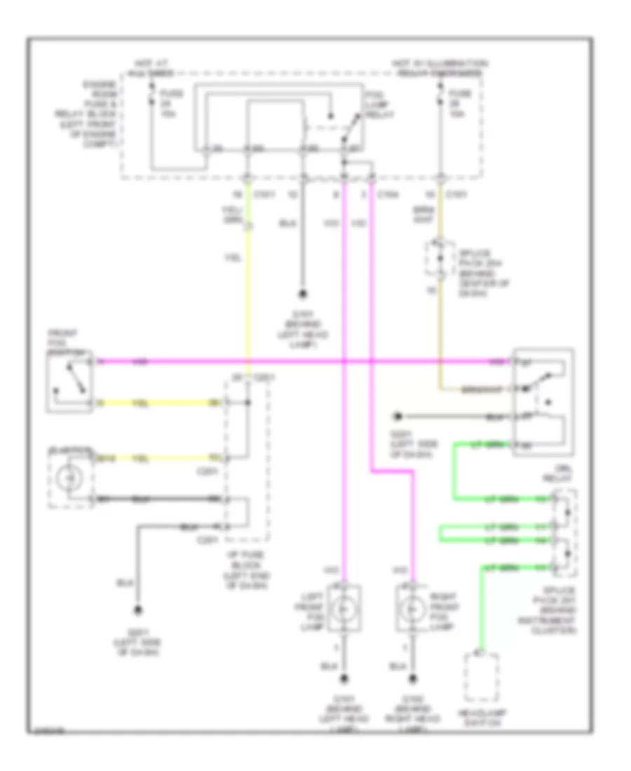
Fog Lamps Wiring Diagram for Suzuki Reno 2006
List of elements for Fog Lamps Wiring Diagram for Suzuki Reno 2006:
- B19
- C101
- C104
- C201
- Cluster
- Drl relay
- Engine room fuse & relay block (left front of engine compt)
- Fog lamp relay
- Front fog switch
- Fuse 10a
- Fuse 15a
- G101 (behind left head lamp)
- G102 (behind right head lamp)
- G201 (left side of dash)
- Headlamp switch
- Hot at all times
- Hot w/ illumination relay energized
- I/p fuse block (left end of dash)
- Left front fog lamp
- Right front fog lamp
- Splice pack 201 (behind instrument cluster)
- Splice pack 204 (behind center of dash)
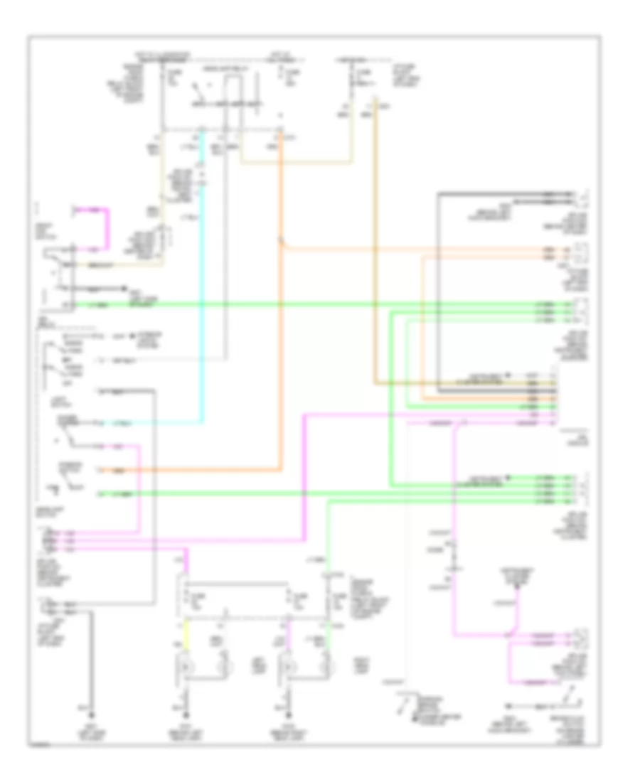
Headlamps Wiring Diagram for Suzuki Reno 2006
List of elements for Headlamps Wiring Diagram for Suzuki Reno 2006:
- Brake fluid switch (on brake master cylinder)
- C101
- C102
- C104
- C201
- Dimmer switch
- Diode
- Drl module
- Drl relay
- Engine room fuse & relay block (left front of engine compt)
- Front fog switch
- Fuse 10a
- Fuse 15a
- Fuse 25a
- G101 (behind left head lamp)
- G102 (behind right head lamp)
- G201 (left side of dash)
- G203 (behind left audio bracket)
- G204 (behind left audio bracket)
- Head
- Headlamp relay
- Headlamp switch
- High
- Hot at all times
- Hot in on
- Hot w/ illumination relay energized
- I/p fuse block (left end of dash)
- Instrument cluster system
- Interior lights system
- Left head lamp
- Light switch
- Low
- Nca
- Off
- Park
- Parking brake switch (under center console)
- Passing switch
- Right head lamp
- Splice pack 201 (behind instrument cluster)
- Splice pack 201 (behind instru- ment cluster)
- Splice pack 201 (behind instrument cluster)
- Splice pack 203 (behind center of dash)
- Splice pack 204 (behind center of dash)
- Splice pack 301 (behind left kick panel)
HORN
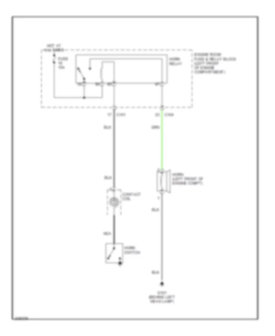
Horn Wiring Diagram for Suzuki Reno 2006
List of elements for Horn Wiring Diagram for Suzuki Reno 2006:
- C101
- C104
- Contact coil
- Engine room fuse & relay block (left front of engine compartment)
- Fuse 15a
- G101 (behind left head lamp)
- Horn (left front of engine compt)
- Horn relay
- Horn switch
- Hot at all times
- Nca
INSTRUMENT CLUSTER
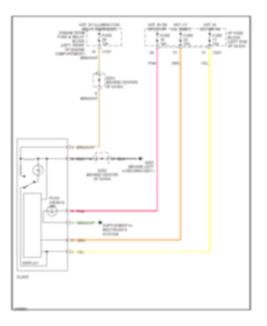
Clock Wiring Diagram for Suzuki Reno 2006
List of elements for Clock Wiring Diagram for Suzuki Reno 2006:
- C101
- C201
- Clock
- Display
- Engine room fuse & relay block (left front of engine compartment)
- Fuse 10a
- Fuse 15a
- G203 (behind left audio bracket)
- Hot at all times
- Hot in acc or on
- Hot in on or start
- Hot w/ illumination relay energized
- I/p fuse block (left end of dash)
- Pass air bag off
- Pnk
- S203 (behind center of dash)
- S204 (behind center of dash)
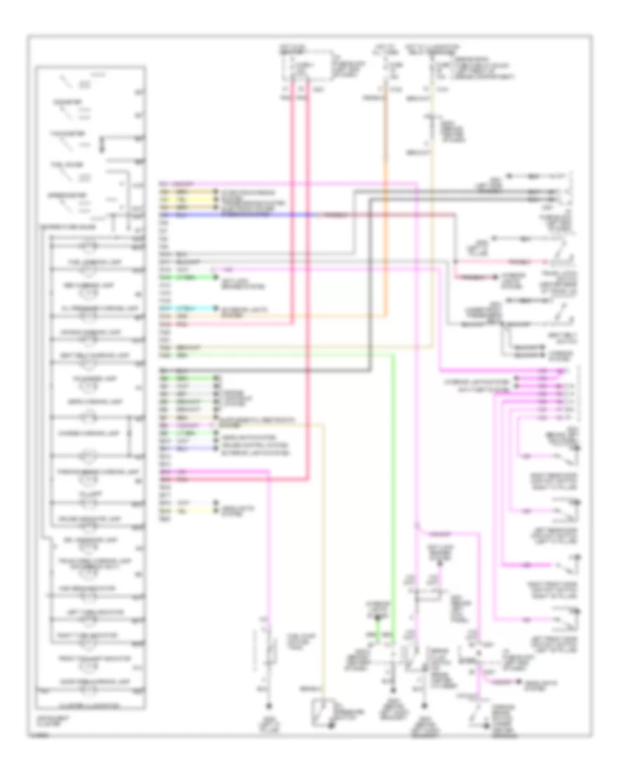
Instrument Cluster Wiring Diagram for Suzuki Reno 2006
List of elements for Instrument Cluster Wiring Diagram for Suzuki Reno 2006:
- A10
- A11
- A12
- A13
- A14
- A15
- A16
- A17
- A18
- A19
- A20
- A21
- A22
- A23
- Abs warning lamp
- Air bag warning lamp
- Anti-lock brakes system
- Anti-theft system
- B10
- B11
- B12
- B13
- B14
- B15
- B16
- B17
- B18
- B19
- B20
- Brake fluid switch (on brake master cylinder)
- C101
- C102
- C201
- Charge warning lamp
- Cluster illumination
- Cruise control system
- Cruise indicator lamp
- Diode
- Door open warning lamp
- Drl indicator lamp
- Engine controls system
- Engine room fuse & relay block (left front of engine compartment)
- Exterior lights system
- Front fog lamp indicator
- Fuel gauge
- Fuel pump (on fuel tank)
- Fuel warning lamp
- Fuse 10a
- Fuse 15a
- Fuse 4 10a
- G201 (left side of dash)
- G203 (behind left audio bracket)
- G204 (behind left audio bracket)
- G301 (under front passenger's seat)
- G302 (left "c" pillar)
- Headlights system
- High beam indicator
- Hold mode lamp
- Hot at all times
- Hot in on or start
- Hot w/ illumination relay energized
- I/p fuse block (left end of dash)
- Instrument cluster
- Interior lights system
- Left front door contact switch (left "b" pillar)
- Left rear door contact switch (left "c" pillar)
- Left turn indicator
- Micom
- Mil lamp
- Odometer
- Oil pressure switch
- Oil pressure warning lamp
- Parking brake switch (under center console)
- Parking brake warning lamp
- Pnk
- Right front door contact switch (right "b" pillar)
- Right rear door contact switch (right "c" pillar)
- Right turn indicator
- S203 (behind center of dash)
- S204 (behind center of dash)
- S301 (behind left kick panel)
- Seat belt switch
- Seat belt warning lamp
- Speedometer
- Ssps warning lamp
- Starting/charging system transmissions system electronic power steering system
- Tachometer
- Temperature gauge
- Trunk latch switch (center rear of trunk lid)
- Trunk open warning lamp (notchback only)
- Warning system
INTERIOR LIGHTS
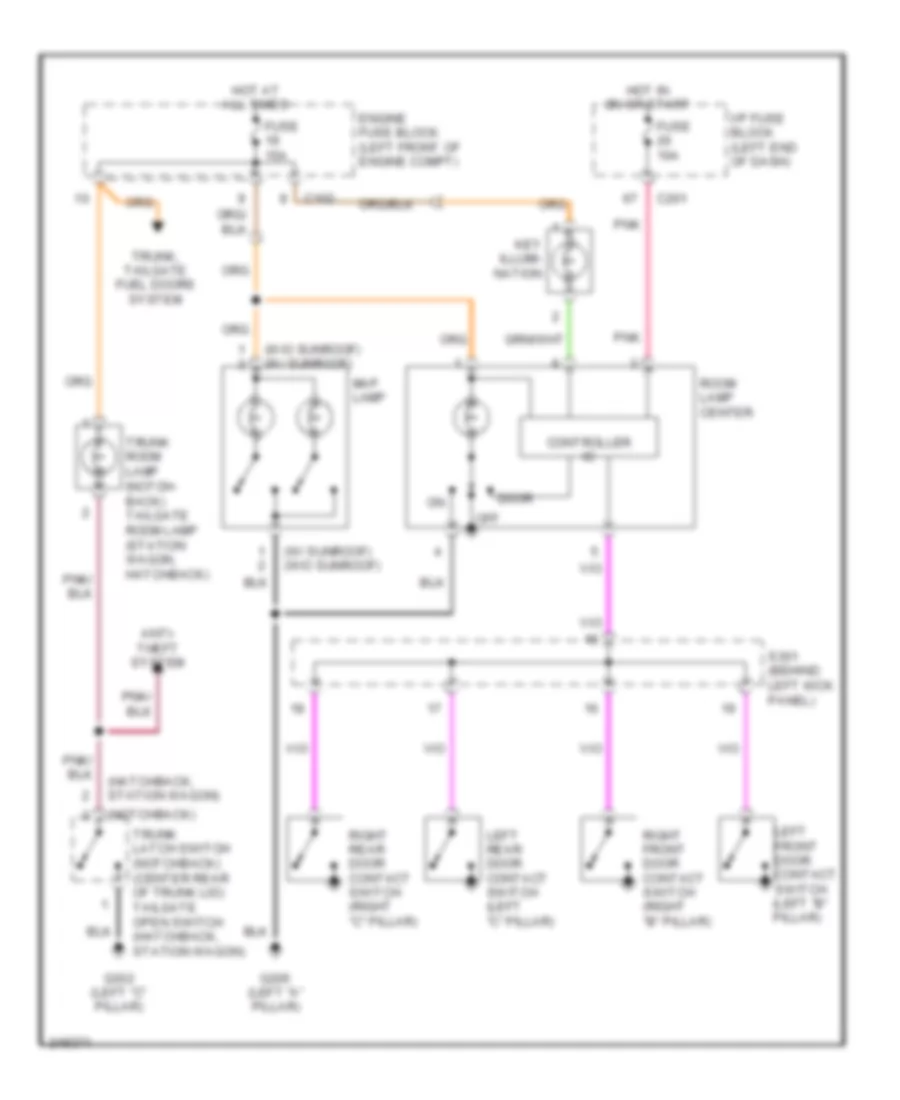
Courtesy Lamps Wiring Diagram for Suzuki Reno 2006
List of elements for Courtesy Lamps Wiring Diagram for Suzuki Reno 2006:
- (hatchback, station wagon)
- (notchback)
- (w/ sunroof) (w/o sunroof)
- (w/o sunroof) (w/ sunroof)
- Anti- theft system
- C102
- C201
- Controller ic
- Door
- Engine fuse block (left front of engine compt)
- Fuse 10a
- Fuse 15a
- G205 (left "a" pillar)
- G302 (left "c" pillar)
- Hot at all times
- Hot in on or start
- I/p fuse block (left end of dash)
- Key illumi- nation
- Left front door contact switch (left "b" pillar)
- Left rear door contact switch (left "c" pillar)
- Map lamp
- Off
- Pnk
- Right front door contact switch (right "b" pillar)
- Right rear door contact switch (right "c" pillar)
- Room lamp center
- S301 (behind left kick panel)
- Trunk latch switch (notchback) (center rear of trunk lid) tailgate open switch (hatchback, station wagon)
- Trunk room lamp (notch- back) tailgate room lamp (station wagon, hatchback)
- Trunk, tailgate fuel doors system
Instrument Illumination Wiring Diagram for Suzuki Reno 2006
List of elements for Instrument Illumination Wiring Diagram for Suzuki Reno 2006:
- A/c control switch
- A10
- A22
- A23
- Ashtray lamp
- Audio
- C101
- Clock
- Dimmer control unit
- Engine fuse block (left front of engine compt)
- Fuse 10a
- Fuse 25a
- G201 (left side of dash)
- G203 (behind left audio bracket)
- Hazard switch
- Head
- Hold mode switch
- Hot at all times
- I/p fuse block (left end of dash)
- Illumination relay
- Instrument cluster
- Light switch
- Off
- Park
- Prndl switch
- S203 (behind center of dash)
- S204 (behind center of dash)
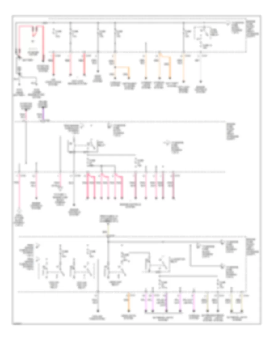
POWER DISTRIBUTION
Power Distribution Wiring Diagram (1 of 3) for Suzuki Reno 2006
List of elements for Power Distribution Wiring Diagram (1 of 3) for Suzuki Reno 2006:
- Air conditioning system
- Anti-lock brakes system
- Anti-theft system
- Battery
- C101
- C102
- C103
- C104
- C105
- C106
- C107
- Cooling fan hi relay
- Cooling fan low relay
- Cooling fans system
- Cruise control system
- Door locks system
- Engine controls system
- Engine fuse block (left front of engine compt)
- Exterior lights system
- From engine a fuse block (diagram 1 of 3)
- From engine fuse block (diagram 1 of 3)
- From fuse 6, in i/p fuse block, (diagram 2 of 3)
- From i/p fuse block (diagram 3 of 3)
- Fuel pump relay
- Fuse 10a
- Fuse 15a
- Fuse 18 15a
- Fuse 20a
- Fuse 25a
- Fuse 30a
- G103 (near battery)
- G105 (under engine start motor)
- Headlamp relay
- Headlights system
- Illumination relay
- Instrument cluster system
- Interior lights system
- Main relay
- Nca
- Pnk
- Red
- Starter motor
- Starting/ charging system
- To engine fuse block (diagram 1 of 3)
- To engine fuse block (diagram 2 of 3)
- To engine fuse block (diagram 3 of 3)
- To fuse 11 engine fuse block (diagram 2 of 3)
- Warning system
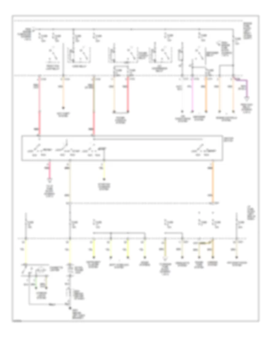
Power Distribution Wiring Diagram (2 of 3) for Suzuki Reno 2006
List of elements for Power Distribution Wiring Diagram (2 of 3) for Suzuki Reno 2006:
- (not used)
- A/c compressor relay
- Acc
- Air conditioning system
- Anti-theft system
- C101
- C102
- C104
- C105
- C106
- C201
- Cigarette lighter
- Defogger relay
- Defogger system
- Engine controls system
- Engine fuse block (left front of eng compt)
- Extra power jack
- From d engine fuse block (diagram 1 of 3)
- From engine fuse block (diagram 1 of 3)
- From main relay (diagram 2 of 3)
- Front fog lamp relay
- Fuse
- Fuse 10a
- Fuse 15a
- Fuse 20a
- Fuse 30a
- G203 (behind left audio bracket)
- Headlights system
- Horn relay
- I/p fuse block (left end of dash)
- Ignition switch
- Instrument cluster system
- Interior lights system
- Lock
- Mirrors system
- Pnk pnk
- Power tops system
- Power window relay
- Power windows system
- Red
- Red red
- Run
- S203 (behind center of dash)
- Shift interlock system
- Sound systems
- Start
- Starting/ charging system
- To engine fuse block (diagram 1 of 3)
- To i/p fuse block (diagram 3 of 3)
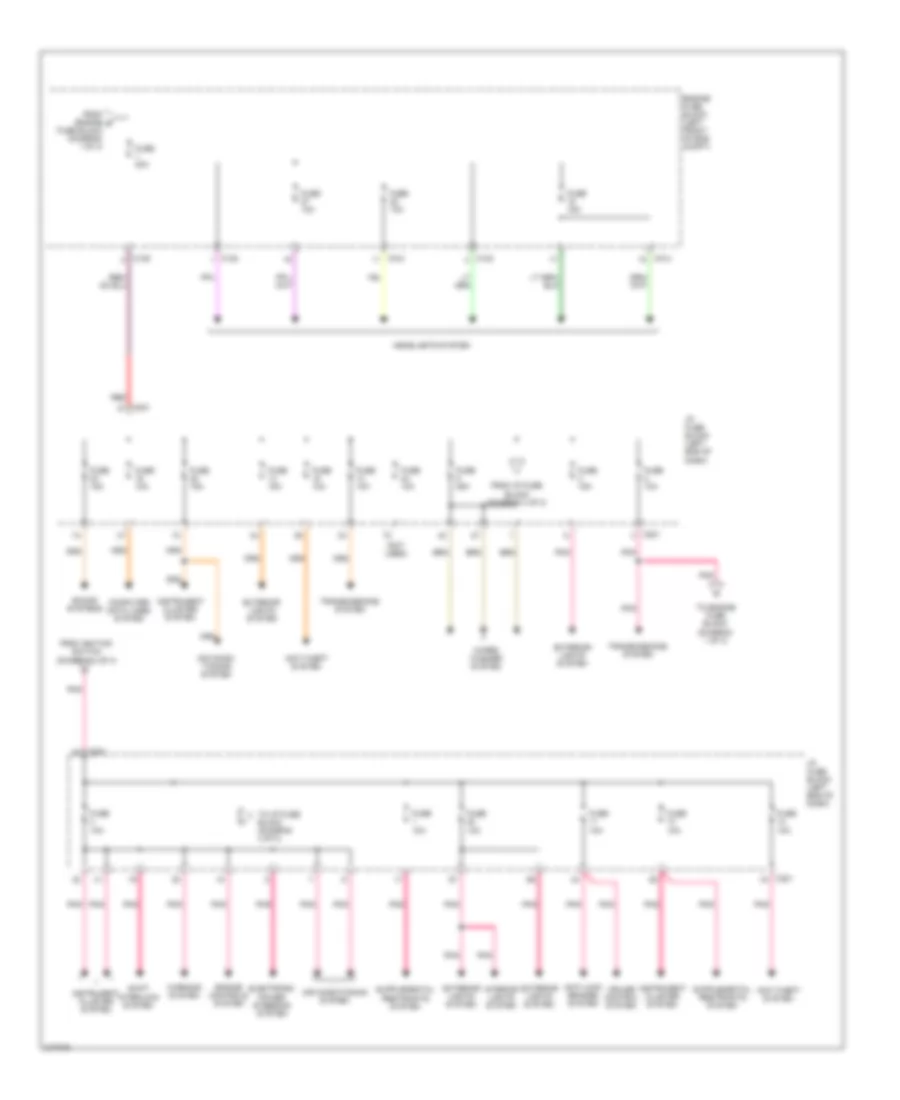
Power Distribution Wiring Diagram (3 of 3) for Suzuki Reno 2006
List of elements for Power Distribution Wiring Diagram (3 of 3) for Suzuki Reno 2006:
- (not used)
- Air condi- tioning system
- Air conditioning system
- Anti-lock brakes system
- Anti-theft system
- C102
- C104
- C105
- C201
- Computer data lines system
- Cruise control system
- Electronic power steering system
- Engine controls system
- Engine fuse block (left front of eng compt)
- Exterior lights system
- From engine g
- From i/p fuse block (diagram 3 of 3)
- From ignition switch (diagram 2 of 3)
- Fuse 10a
- Fuse 15a
- Fuse 25a
- Fuse 30a
- Fuse block (diagram 1 of 3)
- Headlights system
- I/p fuse block (left end of dash)
- Instrument cluster system
- Interior lights system
- Pnk
- Red
- Shift interlock system
- Sound systems
- To engine fuse block (diagram 1 of 3)
- To i/p fuse block (diagram 3 of 3)
- Transmissions system
- Warning system
- Wiper/ washer system
POWER DOOR LOCKS
Power Door Locks Wiring Diagram for Suzuki Reno 2006
List of elements for Power Door Locks Wiring Diagram for Suzuki Reno 2006:
- Anti-theft control unit (under floor console)
- C102
- Central door lock unit
- Door lock switch
- Engine room fuse & relay block (left front of engine compartment)
- Fuse 26 15a
- G204 (behind left audio bracket)
- G301 (under front passenger's seat)
- Hot at all times
- Left front central locking & anti-theft switch
- Left front door actuator (rear of left front door)
- Left rear door actuator (rear of left rear door)
- Lock
- Right front door actuator (rear of right front door)
- Right rear door actuator (rear of right rear door)
- S302 (behind left kick panel)
- Tail gate actuator (left side of tailgate door) (except notchback)
- Un- lock
- Un-lock
POWER MIRRORS
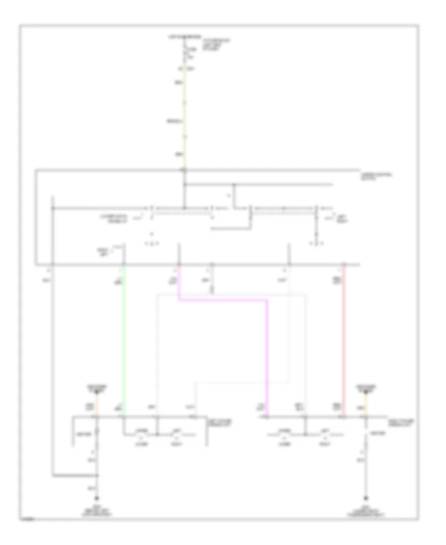
Power Mirrors Wiring Diagram for Suzuki Reno 2006
List of elements for Power Mirrors Wiring Diagram for Suzuki Reno 2006:
- (lower) down
- (raise) up
- C201
- Defogger system
- Fuse 15a
- G204 (behind left audio bracket)
- G301 (under front passenger's seat)
- Heater
- Hot in on or acc
- I/p fuse block (left end of dash)
- Left
- Left power mirror unit
- Lower
- Mirror control switch
- Right
- Right power mirror unit
- Upper
POWER TOP/SUNROOF
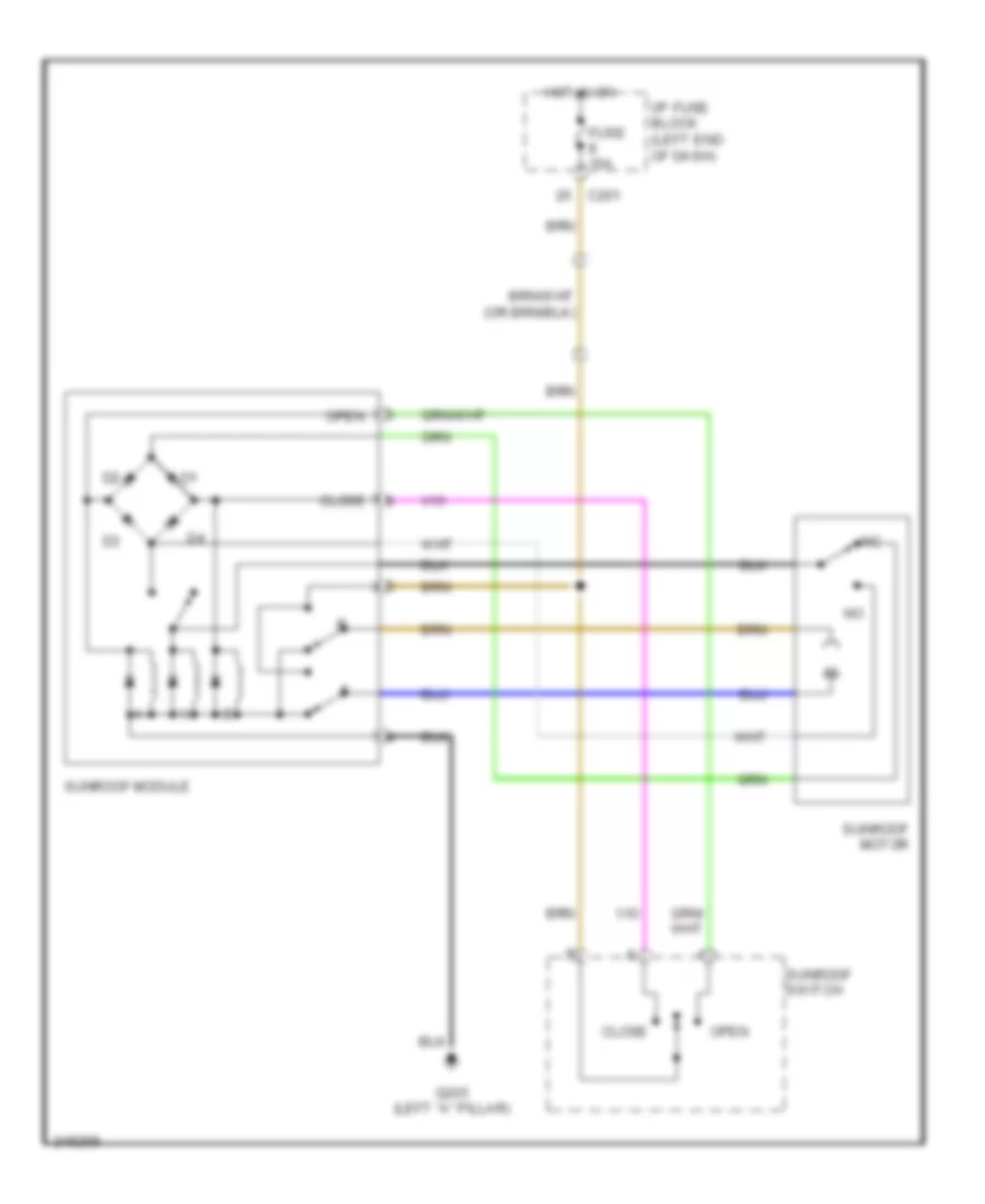
Power Top/Sunroof Wiring Diagram for Suzuki Reno 2006
List of elements for Power Top/Sunroof Wiring Diagram for Suzuki Reno 2006:
- C201
- Close
- Fuse 15a
- G205 (left "a" pillar)
- Hot in on
- I/p fuse block (left end of dash)
- Open
- Sunroof module
- Sunroof motor
- Sunroof switch
POWER WINDOWS
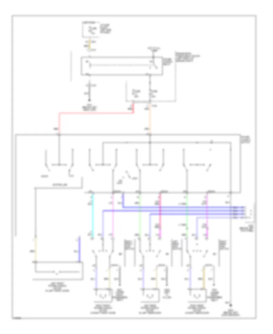
Power Windows Wiring Diagram, with Front & Rear Power Windows for Suzuki Reno 2006
List of elements for Power Windows Wiring Diagram, with Front & Rear Power Windows for Suzuki Reno 2006:
- C101
- C102
- C104
- C201
- Controller
- Down
- Engine room fuse & relay block (left front of engine compt)
- Fuse 10a
- Fuse 20a
- G101 (behind left head lamp)
- G204 (behind left audio bracket)
- G301 (under front passenger's seat)
- G302 (left "c" pillar)
- Hot at all times
- Hot in on
- I/p fuse block (left end of dash)
- Left front power window motor (in left front door)
- Left rear power window motor (in left rear door)
- Left rear sub- switch
- Lock
- Power window relay
- Power window switch
- Red
- Right front power window motor (in right front door)
- Right front sub- switch
- Right rear power window motor (in right rear door)
- Right rear sub- switch
- S301 (behind left kick panel)
- Un- lock
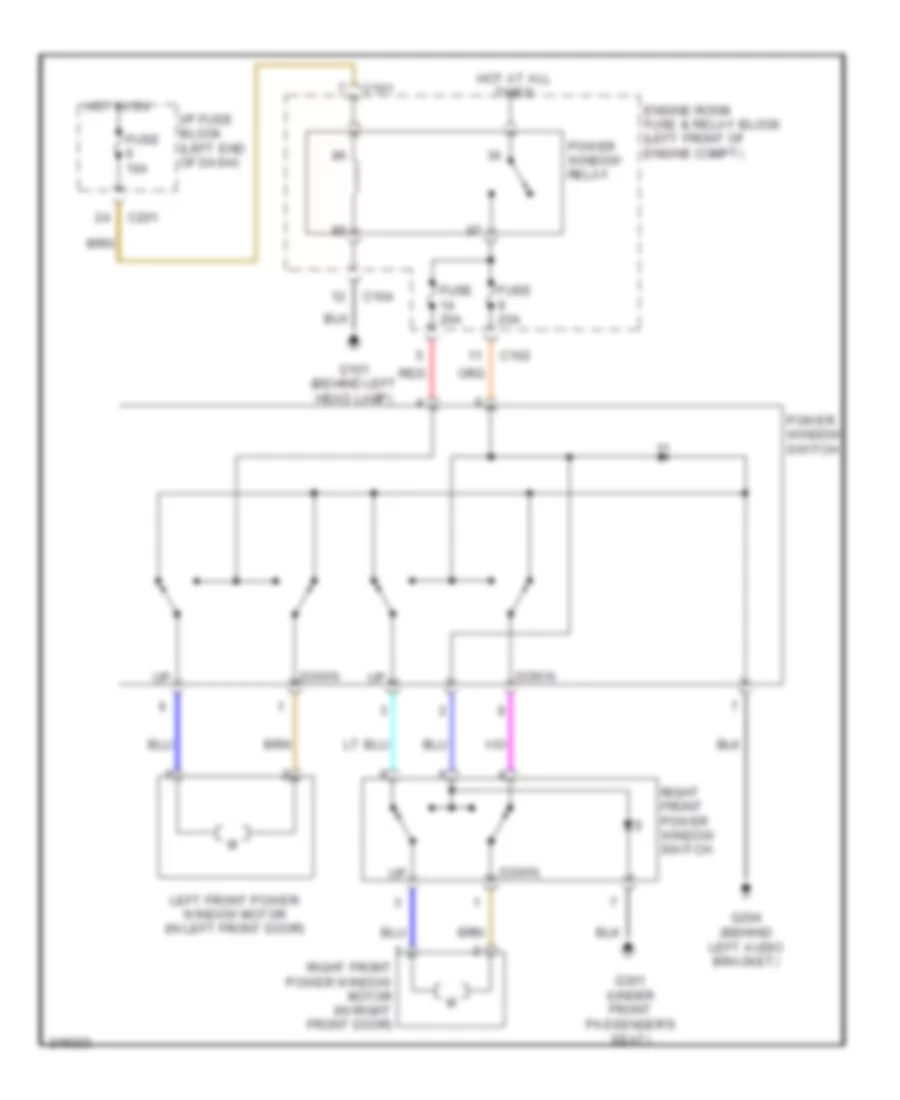
Power Windows Wiring Diagram, with Front Power Windows for Suzuki Reno 2006
List of elements for Power Windows Wiring Diagram, with Front Power Windows for Suzuki Reno 2006:
- C101
- C102
- C104
- C201
- Down
- Engine room fuse & relay block (left front of engine compt)
- Fuse 10a
- Fuse 20a
- G101 (behind left head lamp)
- G204 (behind left audio bracket)
- G301 (under front passenger's seat)
- Hot at all times
- Hot in on
- I/p fuse block (left end of dash)
- Left front power window motor (in left front door)
- Power window relay
- Power window switch
- Red
- Right front power window motor (in right front door)
- Right front power window switch
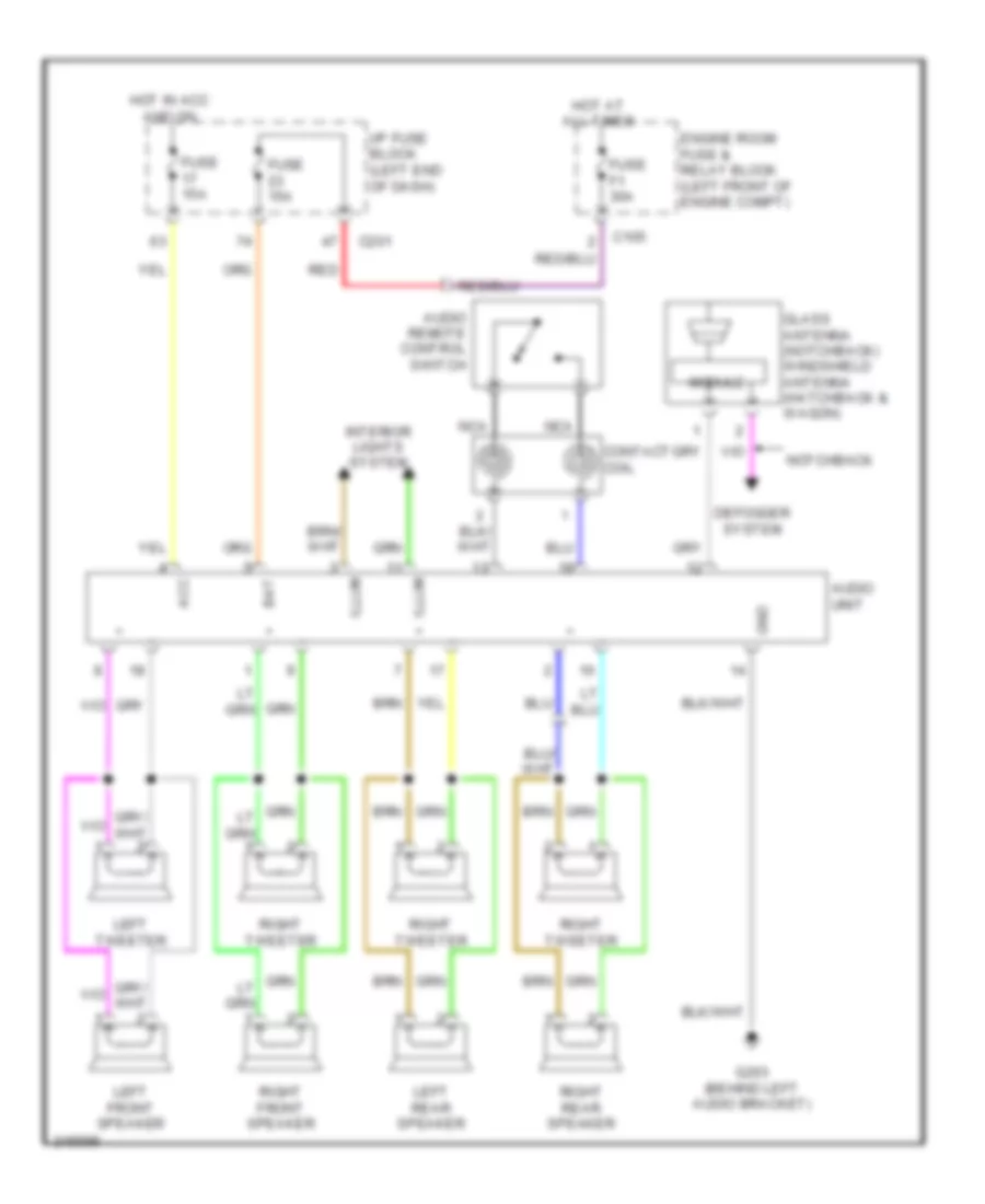
RADIO
Radio Wiring Diagram for Suzuki Reno 2006
List of elements for Radio Wiring Diagram for Suzuki Reno 2006:
- Acc
- Audio remote control switch
- Audio unit
- Bat
- C105
- C201
- Contact coil
- Defogger system
- Engine room fuse & relay block (left front of engine compt)
- Fuse 15a
- Fuse f1 30a
- G203 (behind left audio bracket)
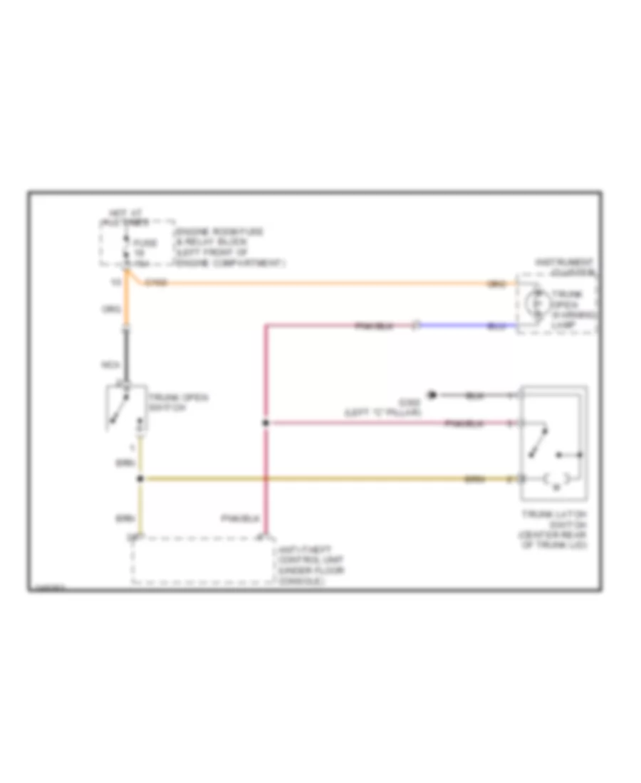
- Glass antenna (notchback) windshield antenna (hatchback & wagon)
- Gnd
- Hot at all times
- Hot in acc and on
- I/p fuse block (left end of dash)
- Illum
- Interior lights system
- Left front speaker
- Left rear speaker
- Left tweeter
- Module
- Nca
- Notchback
- Red
- Right front speaker
- Right rear speaker
- Right tweeter
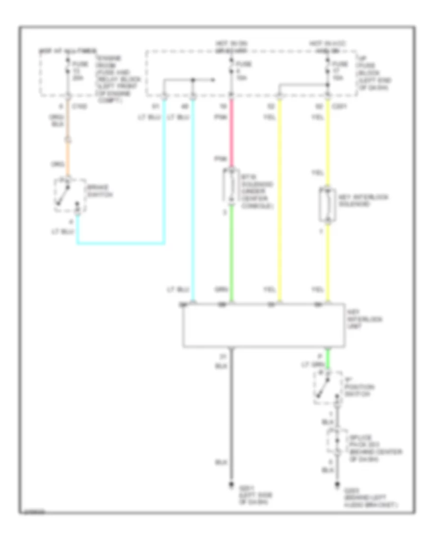
SHIFT INTERLOCK
Shift Interlock Wiring Diagram for Suzuki Reno 2006
List of elements for Shift Interlock Wiring Diagram for Suzuki Reno 2006:
- "p" position switch
- Brake switch
- Btsi solenoid (under center console)
- C102
- C201
- Engine room fuse and relay block (left front of engine compt)
- Fuse 10a
- Fuse 20a
- G201 (left side of dash)
- G203 (behind left audio bracket)
- Hot at all times
- Hot in acc and on
- Hot in on or start
- I/p fuse block (left end of dash)
- Key interlock solenoid
- Key interlock unit
- Pnk
- Splice pack 203 (behind center of dash)
STARTING/CHARGING
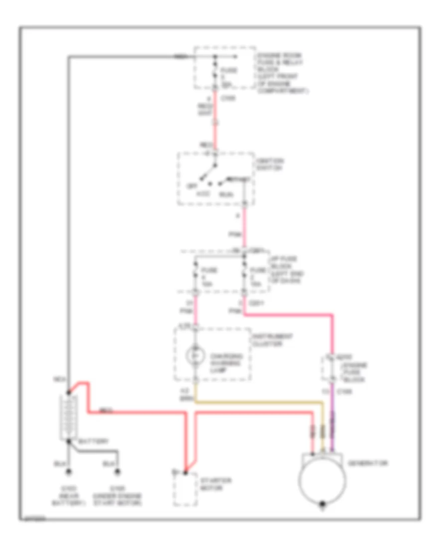
Charging Wiring Diagram for Suzuki Reno 2006
List of elements for Charging Wiring Diagram for Suzuki Reno 2006:
- A19
- Acc
- Battery
- C102
- C105
- C106
- C201
- Charging warning lamp
- Engine fuse block
- Engine room fuse & relay block (left front of engine compartment)
- Fuse 10a
- Fuse 15a
- Fuse 30a
- G103 (near battery)
- G105 (under engine start motor)
- Generator
- I/p fuse block (left end of dash)
- Ignition switch
- Instrument cluster
- Nca
- Off
- Pnk
- Red
- Run
- Start
- Starter motor
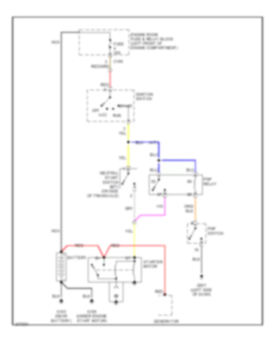
Starting Wiring Diagram for Suzuki Reno 2006
List of elements for Starting Wiring Diagram for Suzuki Reno 2006:
- (a/t)
- Acc
- Battery
- C105
- Engine room fuse & relay block (left front of engine compartment)
- Fuse 30a
- G103 (near battery)
- G105 (under engine start motor)
- G201 (left side of dash)
- Generator
- Ignition switch
- Nca
- Neutral start switch (m/t) (on side of transaxle)
- Off
- Pnp relay
- Pnp switch
- Red
- Run
- Start
- Starter motor
SUPPLEMENTAL RESTRAINTS
Supplemental Restraints Wiring Diagram for Suzuki Reno 2006
List of elements for Supplemental Restraints Wiring Diagram for Suzuki Reno 2006:
- (below left side of dash) data link connector
- Air bag control module (sdm) (under center console)
- Air bag warning ind
- B15
- C201
- Clock
- Contact coil
- Driver air bag module (in steering wheel)
- Driver seat belt pretensioner
- Driver side air bag module (side of driver's seat)
- Fuse f1 10a
- Fuse f10 10a
- Fuse f4 10a
- G202 (behind left audio bracket)
- G301 (under front passenger's seat)
- Ground
- Hot in run or start
- I/p fuse block (left end of dash)
- Ign
- Instrument cluster
- Instrument cluster system
- Left early crash sensor
- Left side air bag sensor (base of left "b" pillar)
- Occupant sensor
- Passenger air bag module (behind right side of dash)
- Passenger air bag off ind
- Passenger seat belt pretensioner
- Passenger side air bag module (side of passenger's seat)
- Pnk
- Right early crash sensor
- Right side air bag sensor (base of right "b" pillar)
- Seat belt switch
TRANSMISSION
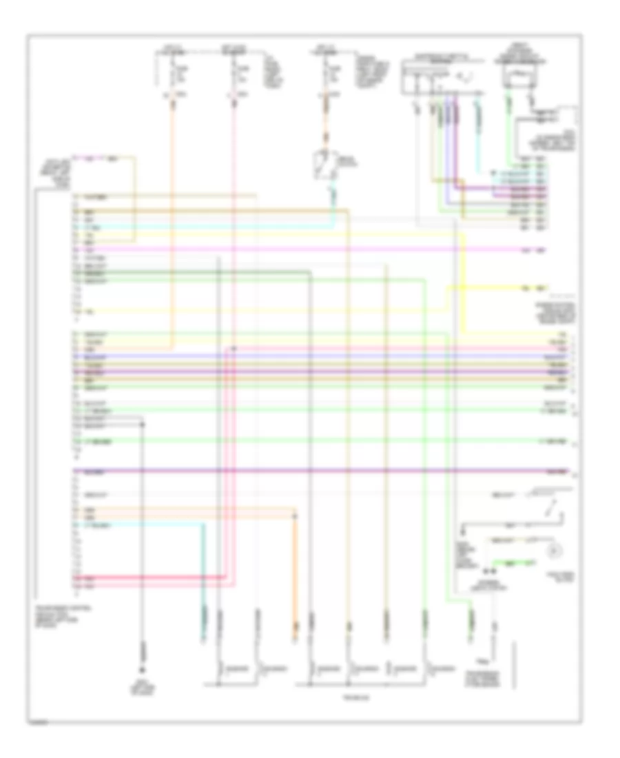
Transmission Wiring Diagram (1 of 2) for Suzuki Reno 2006
List of elements for Transmission Wiring Diagram (1 of 2) for Suzuki Reno 2006:
- (front of engine) engine coolant temperature sensor
- Brake switch
- C102
- C201
- C46
- C63
- Data link connector (below left side of dash)
- E15
- E16
- E25
- E29
- E31
- E32
- E41
- E50
- E51
- E52
- Electronic throttle control
- Engine control module (ecm) (center rear of engine compt)
- Engine room fuse & relay block (left front of engine compt)
- Fuse 10a
- Fuse 15a
- G201 (left side of dash)
- G203 (behind left audio bracket)
- Hold mode switch
- Hot at all times
- Hot in on on start
- I/p fuse block (left end of dash)
- Interior lights system
- Pnk
- S101 (in engine room harness, neat top of transmission)
- Solenoid
- Transaxle
- Transmission control module (tcm) (behind left side of dash)
- Transmission fluid temper- ature sensor
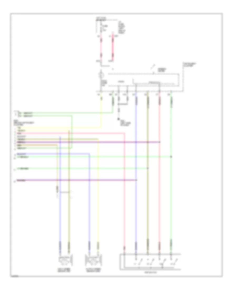
Transmission Wiring Diagram (2 of 2) for Suzuki Reno 2006
List of elements for Transmission Wiring Diagram (2 of 2) for Suzuki Reno 2006:
- A10
- A19
- B15
- C201
- Fuse 10a
- G201 (left side of dash)
- Hold mode ind
- Hot in on or start
- I/p fuse block (left end of dash)
- Input speed sensor (iss)
- Instrument cluster
- Micom
- Output speed sensor (oss)
- P r n d 3 2 1
- Pnk
- Pnp switch
- S202 (behind instrument cluster)
- Speedo- meter
TRUNK, TAILGATE, FUEL DOOR
Trunk, Tailgate, Fuel Door Wiring Diagram for Suzuki Reno 2006
List of elements for Trunk, Tailgate, Fuel Door Wiring Diagram for Suzuki Reno 2006:
- Anti-theft control unit (under floor console)
- C102
- Engine room fuse & relay block (left front of engine compartment)
- Fuse 15a
- G302 (left "c" pillar)
- Hot at all times
- Instrument cluster
- Nca
- Trunk latch switch (center rear of trunk lid)
- Trunk open switch
- Trunk open warning lamp
WARNING SYSTEMS
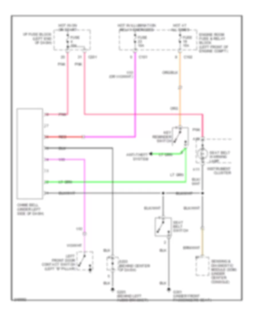
Warning Systems Wiring Diagram for Suzuki Reno 2006
List of elements for Warning Systems Wiring Diagram for Suzuki Reno 2006:
- A11
- A19
- Anti-theft system
- C101
- C102
- C201
- Chime bell (under left side of dash)
- Engine room fuse & relay block (left front of engine compt)
- Fuse 10a
- Fuse 15a
- G203 (behind left audio bracket)
- G301 (under front passenger's seat)
- Hot at all times
- Hot in illumination relay energized
- Hot in on or start
- I/p fuse block (left end of dash)
- Instrument cluster
- Key reminder switch
- Left front door contact switch (left "b" pillar)
- Pnk
- Red
- S203 (behind center of dash)
- Seat belt switch
- Seat belt warning lamp
- Sensing & diagnostic module (sdm) (under center console)
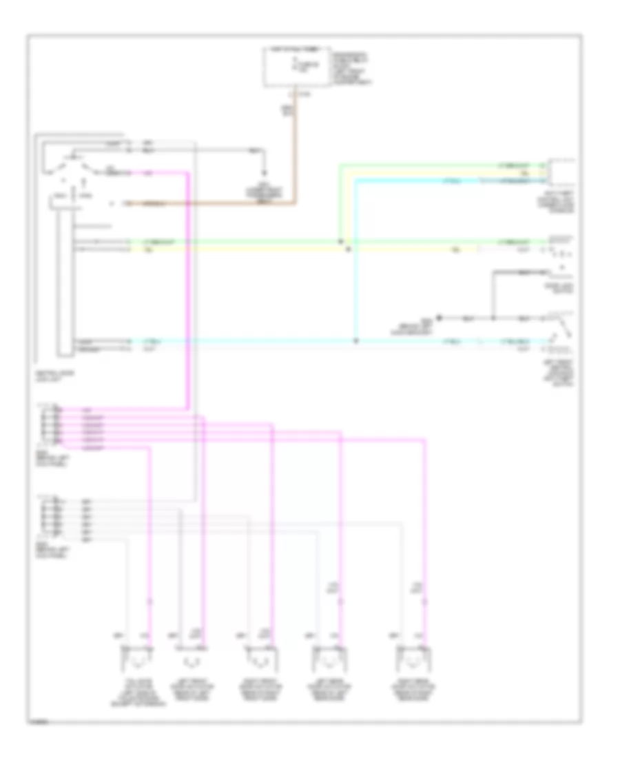
WIPER/WASHER
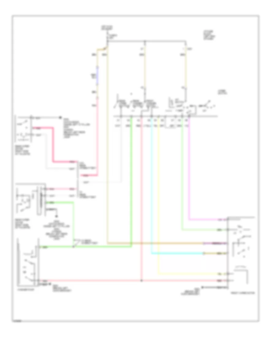
Wiper/Washer Wiring Diagram for Suzuki Reno 2006
List of elements for Wiper/Washer Wiring Diagram for Suzuki Reno 2006:
- C201
- Controller
- Front washer switch
- Front wiper motor
- Fuse 9 25a
- G204 (behind left audio bracket)
- G402 (hatch back) (inside left "c" pillar) g304 (wagon) (below left rear combination lamp)
- Hot in on or start
- I/p fuse block (left end of dash)
- Int
- Int switch
- Off
- Pnk
- Rear washer switch
- Rear wiper motor (right side of tailgate)
- Rear wiper switch
- Red
- W/ rear intermittent
- W/o rear intermittent
- Washer pump
- Wiper switch

 Čeština
 Dansk
Dansk Deutsch
 Ελληνικά
 English
 English
 Español
 Suomi
Suomi Français
 Français
 עברית
עברית Hrvatski
 Magyar
 Italiano
 日本語
日本語 한국어
한국어 Nederlands
 Polski
 Português
 Português
 Русский
 Slovenčina
 Slovenščina
 Svenska
 Türkçe
 中文 (中国)