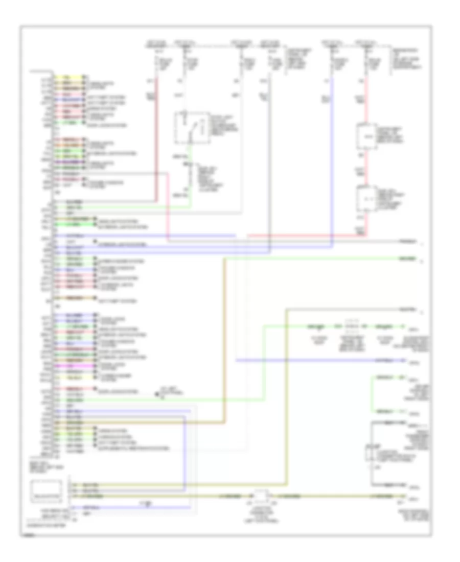
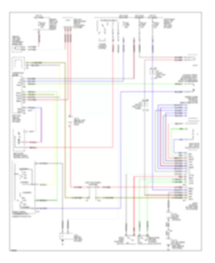
AIR CONDITIONING
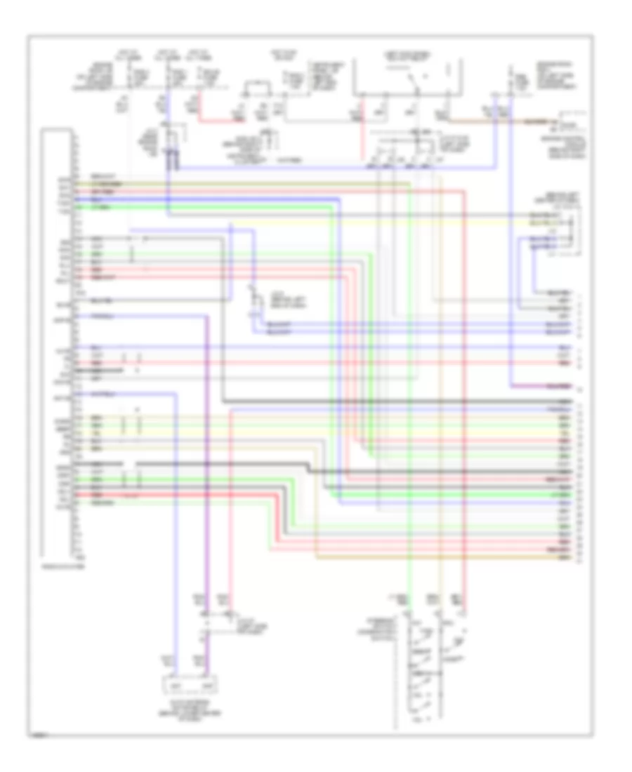
Automatic A/C Wiring Diagram (1 of 3) for Toyota Sequoia SR5 2004
 https://portal-diagnostov.com/license.html
Automotive Electricians Portal FZCO
Automotive Electricians Portal FZCO
https://portal-diagnostov.com/license.html
https://portal-diagnostov.com/license.html
Automotive Electricians Portal FZCO
Automotive Electricians Portal FZCO
List of elements for Automatic A/C Wiring Diagram (1 of 3) for Toyota Sequoia SR5 2004:
- (behind right end of dash)
- (behind right side of instrument cluster) sub j/b 4
- (on left side of engine compt) engine room j/b
- (on left side of engine compt, near engine room j/b) junction connector 3
- A/c control (rear heater control panel) (w/ rear a/c)
- A/c evaporator temperature sensor (rear) (w/ rear a/c) (on right rear of vehicle)
- A/c power transistor (w/ rear a/c) (on right rear of vehicle)
- A/c water valve (rear) (w/ rear a/c) (on right rear of vehicle)
- A/cs
- A20
- Ac1
- Acc
- Air vent mode control servo motor (rear) (w/ rear a/c) (on right rear of vehicle)
- B/l
- B/l2
- Bk (at right "b" pillar)
- Blower motor (rear) (w/ rear a/c) (on right rear of vehicle)
- Blw
- Blwc
- C10
- Cig fuse 15a
- Clk
- Clkr
- D j48
- Dpd
- E j48
- E/m1
- E10
- E20
- Engine room r/b 2 (on left side of engine compt)
- Fac2
- Face
- Foot
- Gnd
- Hot in acc or on
- Hot in on or start
- Htr fuse 10a
- I19
- I20
- I5 (in dash harness, behind right side of dash)
- Ig (at right kick panel)
- Ig+
- Illum
- Instrument panel j/b (behind left end of dash)
- Integration control & panel (behind center of dash)
- Interior lights system
- J j49
- Junction connector 16
- Junction connector 43 (right side of dash)
- Junction connector 48 & 49 (right kick panel)
- K j49
- Mch
- Mcool
- Mg clt relay
- Mhh
- Mhot
- Pnk
- Psw
- Red
- Rhr
- Sg-1
- Spd
- Stx
- Swd
- Tam
- Tec
- Tgls
- Tph
- Vmc
- W/ rear a/c
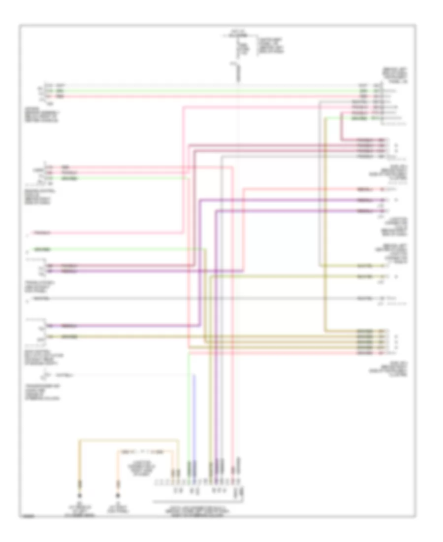
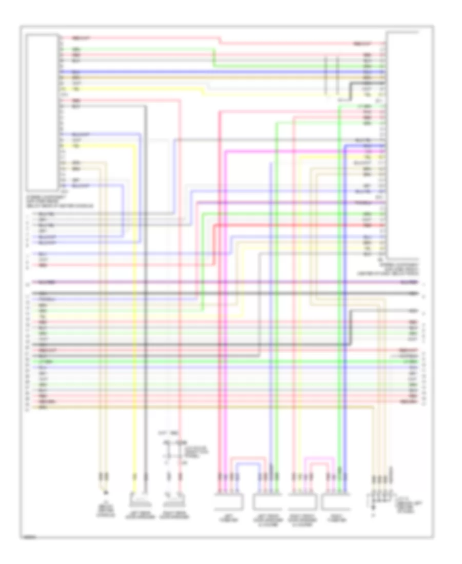
Automatic A/C Wiring Diagram (2 of 3) for Toyota Sequoia SR5 2004
List of elements for Automatic A/C Wiring Diagram (2 of 3) for Toyota Sequoia SR5 2004:
- (w/ rear a/c) rr heater relay
- A/c ambient temperature sensor (on left front of engine compt)
- A/c condenser fan motor (on center front of engine compt)
- A/c magnetic clutch & lock sensor (on left front of engine compt)
- A/c triple pressure switch (on right front of engine compt)
- Blower motor (front) (behind lower right side of dash)
- Blower motor control
- Cds fan fuse 25a
- Cds fan relay
- Dual
- Ea (at right radiator side support)
- Ec (at rear of left cylinder head)
- Engine room r/b 2 (on left side of engine compt)
- Fusible link block (in engine room j/b)
- Gnd
- Heater fuse 40a
- Heater relay
- Hot at all times
- I5 (in dash harness, behind right side of dash)
- Junction connector 18 (behind right end of dash)
- Junction connector 5 (on left side of engine compartment, near engine room j/b)
- Red
- Rr heater fuse 30a
- Single
- W/ rear a/c
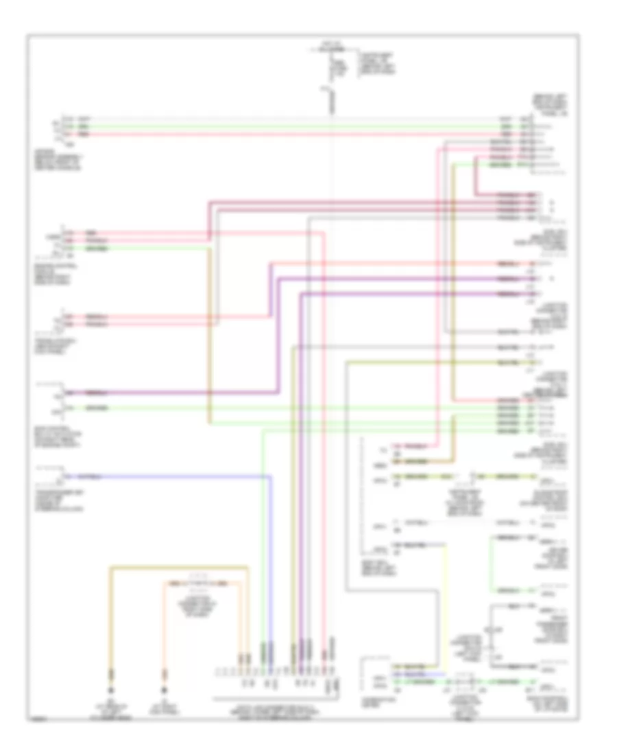
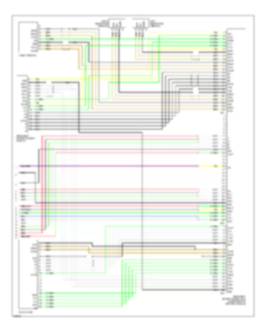
Automatic A/C Wiring Diagram (3 of 3) for Toyota Sequoia SR5 2004
List of elements for Automatic A/C Wiring Diagram (3 of 3) for Toyota Sequoia SR5 2004:
- (behind right end of dash) junction connector 17
- (behind right side of instrument cluster) sub j/b 3
- (in dash harness, behind right side of dash)
- (left end of dash) junction connector 35 & 36
- A/c evaporator temperature sensor (front) (behind right center of dash)
- A/c room temperature sensor (front) (behind lower left center of dash)
- A/c room temperature sensor (rear) (w/ rear a/c) (front of left quarterpanel)
- A/c solar sensor (on top left side of dash)
- A/cs
- A10
- Acid
- Acld
- Acmg
- Aif
- Air
- Air inlet control servo motor (behind right side of dash)
- Air mix control servo motor (front) (behind lower right side of dash)
- Air vent mode control servo motor (front) (behind lower left side of dash)
- B/l
- Combination meter
- D10
- D12
- Def
- Engine control module (ecm) (behind right side of dash)
- Engine controls system
- Engine coolant temperature sensor (on right front of engine)
- Face
- Fdef
- Foot
- Frs
- Gauge fuse 15a
- Gnd
- Hot in on or start
- I21
- I22
- Ig (at right kick panel)
- Ign
- Instrument panel j/b (behind left end of dash)
- Integration control & panel (behind center of dash)
- J29 i
- J30 b
- J35
- J36
- Junction connector 1 (on right front of engine compartment)
- Junction connector 29 & 30 (left kick panel)
- Junction connector 43 (right side of dash)
- Junction connector 8 (behind left end of dash)
- Lcki
- Rec
- Red
- S5-1
- S5-3
- Sg-2
- Sg-3
- Sg-4
- Sg-5
- The
- Thw
- Thwo
- Tp1
- Tpd
- W/ rear a/c
ANTI-LOCK BRAKES
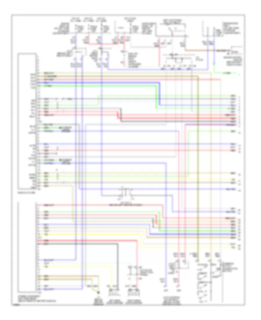
Anti-lock Brakes Wiring Diagram (1 of 2) for Toyota Sequoia SR5 2004
List of elements for Anti-lock Brakes Wiring Diagram (1 of 2) for Toyota Sequoia SR5 2004:
- (in engine harness, near brake master cylinder)
- (near engine room j/b)
- (on brake master cylinder)
- +bm
- +bo
- +bs
- A18
- A19
- Abs fuse 60a
- Active brake booster (on left rear of engine compartment)
- Bst
- Bstp
- Bsw
- Canh
- Canl
- D/g
- Data link connector (dlc) 3 (behind lower left side of dash, right of steering column)
- E4 (in engine harness, near brake master cylinder)
- Fl+
- Fl-
- Fr+
- Fr-
- Fusible link block (in engine room j/b)
- Gnd1
- Gnd2
- Gyaw
- Hot at all times
- Ig1
- Instrument panel j/b (behind left end of dash)
- J14
- J15
- J48 j
- J49 d
- Junction connector 14 & 15 (behind right end of dash)
- Junction connector 28
- Junction connector 48 & 49 (right kick panel)
- Junction connector 8 (behind left end of dash)
- K12
- Left front abs speed sensor (on left front wheel)
- Left rear abs speed sensor (on left rear wheel)
- Master cylinder pressure sensor 1
- Master cylinder pressure sensor 2
- Pedal stroke speed sensor
- Pim
- Pmc
- Pmc2
- Pnk
- Psnc
- Psno
- Red
- Right front abs speed sensor (on right front wheel)
- Right rear abs speed sensor (on right rear wheel)
- Rl+
- Rl-
- Rr+
- Rr-
- S25
- S26
- Short connector (vsc)
- Sil
- Skid control ecu (w/actuator) (on right rear of engine compartment)
- Ss1
- Ss2
- Stop fuse 15a
- Stoplight switch (on bracket above brake pedal)
- Stp
- Sts
- Sub j/b 4 (behind right side of inst- rument cluster)
- Sub j/b 4 (behind right side of instrument cluster)
- Vcm
- Vcm2
- Vcp
- Vscw
- Vys
Anti-lock Brakes Wiring Diagram (2 of 2) for Toyota Sequoia SR5 2004
List of elements for Anti-lock Brakes Wiring Diagram (2 of 2) for Toyota Sequoia SR5 2004:
- (2wd)
- (4wd)
- (behind left end of dash)
- (behind right side of dash) engine control module
- (left side of dash) junction connector 37 & 38
- 2wd
- 4wd
- 4wd control ecu (behind right center of dash)
- Abs ind
- Bat
- Brake
- Brake fluid level warning switch (on brake fluid reservoir)
- Brake inhibit relay (behind left center of dash)
- Brl
- Combination meter
- Cpu
- Csw
- D12
- Ecu-ig fuse 10a
- Eng+
- Eng-
- Ess
- Exi2
- Exterior lights system
- G pnk
- Gauge fuse 15a
- Gnd
- H red
- Hot in on or start
- I5 (behind right side of dash)
- Ig (at right kick panel)
- Ig1
- Im (below center console)
- Ind
- Ind2
- Instrument panel j/b (behind left end of dash)
- Integration control & panel (behind center of dash)
- Ipo
- J14
- J37
- J38
- Junction conn- ector 43 (right side of dash)
- Junction connector 14 & 15 (behind j15 right end of dash)
- Junction connector 17 (behind right end of dash)
- Junction connector 18 (behind right end of dash)
- Lvl2
- Neo
- Park/ neutral position switch (on transmission)
- Parking brake switch (behind left side of dash, on parking brake lever)
- Pkb2
- Pnk
- Red
- Rss
- Slip ind
- Ss1+
- Ss1-
- Steering angle sensor (inside of steering trig column)
- Sub j/b 3 (behind right side of instrument cluster)
- Sub j/b 4 (behind right side of instrument cluster)
- Trac off ind
- Transfer position detection switch 1 (on transfer case)
- Translate ecu (above right kick panel)
- Trc+
- Trc-
- Trig
- Vsc off ind
- Vsc trac
- Vsc warning buzzer
- Vsc+
- Vsc-
- Yaw rate sensor (below rear of center console)
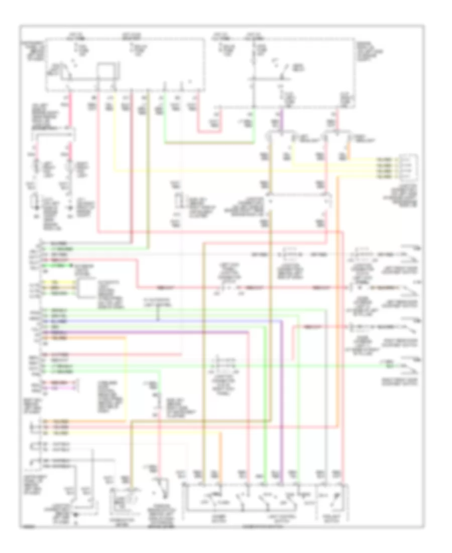
ANTI-THEFT
Forced Entry Wiring Diagram (1 of 3) for Toyota Sequoia SR5 2004
List of elements for Forced Entry Wiring Diagram (1 of 3) for Toyota Sequoia SR5 2004:
- (behind left side of dash) (w/ anti-theft) glass breakage sensor microphone
- (inside of steering column) (w/ anti-theft) glass breakage sensor ecu
- A13
- Act+
- Act-
- Actd
- B10
- Bdr
- Becu
- Body ecu (behind left end of dash)
- Bzr
- C10
- Dcty
- Diode (interior light 1) (at base of right "b" pillar)
- Diode (interior light 2) (at base of left "b" pillar)
- Door 2 fuse 30a
- Ecu-b fuse 7.5a
- Engine room j/b (on left side of engine compt)
- Exterior lights system
- Gb+b
- Gbig
- Gbs
- Gbs1
- Gnd
- Hcty
- Headlights system
- Horns system
- Hot at all times
- Hot in on or start
- Hrly
- Htr fuse 10a
- Ie (at left kick panel)
- Ig (at right kick panel)
- Ind
- Instrument panel j/b (behind left end of dash)
- J10
- J11
- J31
- J33
- J34
- J44
- J45
- Junction conn- ector 44 & 45
- Junction connector
- Junction connector (behind left end of dash)
- Junction connector 10 & 11 (behind j10
- Junction connector 31 & 32 (left kick j32 panel)
- Junction connector 33 & 34
- Junction connector 44 & 45
- Junction connector 5
- Ksw
- Left center of dash)
- Left front door courtesy switch
- Left rear door courtesy switch
- Lswl
- Lswr
- Mi+
- Mi-
- Mic+
- Mic-
- Mpx1
- Mpx2
- Nca
- Pcty
- Pnk
- Prg
- Rda
- Right front door courtesy switch
- Right rear door courtesy switch
- Rlcy
- Rrcy
- Sub j/b 4 (behind right side of instrument cluster)
- Theft deterrent horn (w/ anti- theft) (left side of engine compt)
- Trly
- Unlock warning switch
- Wireless door control receiver (w/ wireless door locks) (behind left center of dash)
- Wireless door lock control buzzer (w/ wireless door locks) (on left front of engine compt, behind headlight)
Forced Entry Wiring Diagram (2 of 3) for Toyota Sequoia SR5 2004
List of elements for Forced Entry Wiring Diagram (2 of 3) for Toyota Sequoia SR5 2004:
- Bh (at left "b" pillar)
- Bk (at right "b" pillar)
- Combination meter
- Engine hood courtesy switch (on left center of radiator support)
- F10
- Instrument cluster system
- Instrument panel j/b (behind left end of dash)
- J10
- J11
- J31
- J32
- J33
- J34
- J44
- J45
- Junction connector 1
- Junction connector 10 & 11 (behind left center of dash) j11
- Junction connector 31 & 32 (left kick j32 panel)
- Junction connector 31 & 32 (left kick panel)
- Junction connector 33 & 34
- Junction connector 44 & 45
- Junction connector 8 (behind left end of dash)
- Left front door lock motor, door key lock/unlock switch & door unlock detection switch
- Left rear door lock motor & door unlock detection switch
- Right rear door lock motor & door unlock detection switch
- Security
Forced Entry Wiring Diagram (3 of 3) for Toyota Sequoia SR5 2004
List of elements for Forced Entry Wiring Diagram (3 of 3) for Toyota Sequoia SR5 2004:
- Act+
- Act-
- B10
- B11
- Back door courtesy switch
- Back door ecu (on left side of liftgate)
- Back door key lock & unlock switch
- Back door lock motor & back door unlock detection switch
- Bdcy
- Bdr
- Becu
- Bkl
- Bkul
- Cpub
- Ctye
- Driver door ecu (in left front door)
- Ecu-ig fuse 10a
- F17
- Front passenger door ecu (in right front door)
- G11
- G15
- Gnd
- Hot at all times
- Hot in run or start
- Instrument panel j/b (behind left end of dash)
- J29
- J30
- J33
- Junction conn- ector 12
- Junction connector 19 (on left rear of cargo area,
- Junction connector 22 (on left side of liftgate)
- Junction connector 29 & 30 (left kick panel)
- Junction connector 33 & 34 (left kick j34 panel)
- Junction connector 37
- Junction connector 6 & 7 (behind left kick panel)
- Junction connector 8
- Keye
- Kul
- Lswb
- Lswd
- Lswe
- Lswp
- Mpx1
- Mpx2
- Pkl
- Pkul
- Pwr 1 fuse 25a
- Pwr 2 fuse 25a
- Pwr 5 fuse 30a
- Red
- Right front door lock motor, door key lock/unlock switch & door unlock detection switch
- Sig
Immobilizer Wiring Diagram for Toyota Sequoia SR5 2004
List of elements for Immobilizer Wiring Diagram for Toyota Sequoia SR5 2004:
- (behind lower left side of dash, right of steering column) data link connector 3
- +b2
- Agnd
- Ant1
- Ant2
- Batt
- Body ecu (behind left end of dash)
- C j33
- Code
- Combination meter
- Cty
- E17
- Ecu-b fuse 7.5a
- Efi 1 fuse 20a
- Efi relay
- Efii
- Efio
- Engine control module (behind right side of dash)
- Engine room j/b (on left side of engine compt)
- Eom
- F10
- Gnd
- Hot at all times
- Hot in run or start
- I j34
- Ig (at right kick panel)
- Ign1 fuse 10a
- Igsw
- Imi
- Imo
- Ind
- Instrument panel j/b (behind left end of dash)
- J/c 14 & 15 (behind right end of dash)
- J/c 28 (near engine room j/b)
- J/c 33 & 34
- J/c 43
- J/c 8 (behind left end of dash)
- J/c 9 (behind left end of dash)
- J14
- J15
- K12
- Ksw
- Ksw2
- Left front door courtesy switch
- Mrel
- Op3
- Rxck
- Security indicator
- Sub j/b 4 (behind right side of instrument cluster)
- Transponder key amplifier (inside of steering column)
- Transponder key coil
- Transponder key computer (inside of steering column)
- Txct
- Unlock warning switch
- Vc12
BODY CONTROL MODULES
Body Control Modules Wiring Diagram (1 of 2) for Toyota Sequoia SR5 2004
List of elements for Body Control Modules Wiring Diagram (1 of 2) for Toyota Sequoia SR5 2004:
- (at left kick panel) ie
- A13
- Acc
- Act+
- Act-
- Actd
- Anti-theft system
- B11
- Back door ecu (on left side of liftgate)
- Bdn
- Bdr
- Becu
- Body ecu (behind left end of dash)
- Bup
- Bzr
- Cltb
- Clte
- Clts
- Combination meter
- Dcty
- Dim
- Door 2 fuse 30a
- Door locks system
- Driver door ecu (in left front door)
- Ecu-b fuse 7.5a
- Ecu-ig fuse 10a
- Engine room j/b (on left side of engine compartment)
- Exterior lights system
- Ffog
- Front passenger door ecu (in right front door)
- G10
- G11
- G12
- Gbs
- Gnd
- Gsw
- H-on
- Hcty
- Head
- Headlights system
- High beam ind
- Hind
- Horn
- Horns system
- Hot at all times
- Hot in acc or on
- Hot in on or start
- Hrly
- Ile
- Ind
- Instrument panel j/b (behind left end of dash)
- Interior lights system
- J29
- J30
- J31
- J32
- Junction connector 29 & 30 (left kick panel)
- Junction connector 31 & 32 (left kick panel)
- Ksw
- Ksw2
- Lswl
- Lswr
- Mpx1
- Mpx2
- Mpx3
- Obd2
- Pcty
- Pkb
- Pnk
- Power windows system
- Prg
- Rad 2 fuse 7.5a
- Rda
- Red
- Rlcy
- Rld
- Rlu
- Roof
- Rrcy
- Rrd
- Rru
- Rwc1
- Rwls
- Rww
- Security ind
- Sliding roof control ecu (on center front of roof)
- Solid state
- Stop fuse 15a
- Stop light switch (on bracket above brake pedal)
- Stp1
- Sub j/b 4 (behind right side of instrument cluster)
- Tail
- Trly
- W/ drl
- W/ moon
- Warning system
- Wig
- Wiper/washer system
- Wsh fuse 25a
Body Control Modules Wiring Diagram (2 of 2) for Toyota Sequoia SR5 2004
List of elements for Body Control Modules Wiring Diagram (2 of 2) for Toyota Sequoia SR5 2004:
- (behind left center of dash) junction connector 10 & 11
- (behind left end of dash) instrument panel j/b
- A17
- A19
- A20
- Air bag sensor assembly (below front of center console)
- Bat
- D/g
- Data link connector (dlc) 3 (behind lower left side of dash, right of steering column)
- E14
- Ec (at rear of of left cylinder head)
- Engine control module (behind right side of dash)
- F15
- Hot at all times
- Ig (at right kick panel)
- Instrument panel j/b (behind left end of dash)
- J10
- J11
- J14
- J15
- Junction connector 14 & 15 (behind right end of dash)
- Junction connector 43 (right side of dash)
- Obd fuse 7.5a
- Op3
- Red
- Sil
- Skid control ecu with actuator (on right rear of engine compt)
- Sub j/b 4 (behind right side of instrument cluster)
- Translate ecu (above right kick panel)
- Transponder key computer (inside of steering column)
- Wsfe
COMPUTER DATA LINES
Computer Data Lines Wiring Diagram for Toyota Sequoia SR5 2004
List of elements for Computer Data Lines Wiring Diagram for Toyota Sequoia SR5 2004:
- (behind left end of dash) instrument panel j/b
- A17
- A19
- A20
- Air bag sensor assembly (below front of center console)
- B j29
- B11
- Back door ecu (on left side of liftgate)
- Bat
- Body ecu (behind left end of dash)
- Combination meter
- D/g
- Data link connector (dlc) 3 (behind lower left side of dash, right of steering column)
- Driver door ecu (in left front door)
- E14
- Ec (at rear of of left cylinder head)
- Engine control module (behind right side of dash)
- F15
- Front passenger door ecu (in right front door)
- G12
- Hot at all times
- Ig (at right kick panel)
- Instrument panel j/b (behind left end of dash)
- Instrument panel j/b (w/ moon roof) (behind left end of dash)
- J10
- J11
- J14
- J15
- J30
- J31
- J32
- Junction connector 10 & 11 (behind left center of dash)
- Junction connector 14 & 15 (behind right end of dash)
- Junction connector 29 & 30 (left kick panel)
- Junction connector 31 & 32 (left kick panel)
- Junction connector 43 (right side of dash)
- Mpx1
- Mpx2
- Mpx3
- Obd fuse 7.5a
- Obd2
- Op3
- Red
- Sil
- Skid control ecu w/ actuator (on right rear of engine compt)
- Sliding roof control ecu (on center front of roof)
- Sub j/b 4 (behind right side of instrument cluster)
- Translate ecu (above right kick panel)
- Transponder key computer (inside of steering column)
- Wsfe
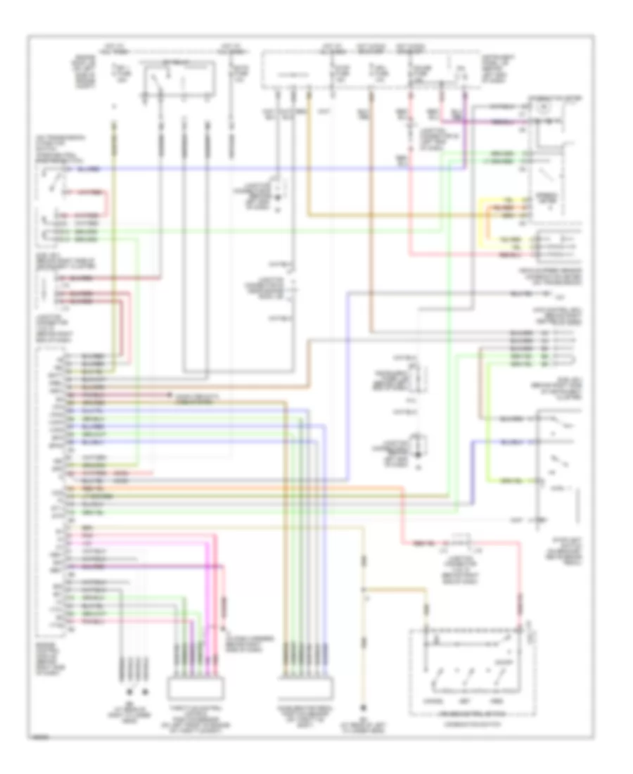
CRUISE CONTROL
Cruise Control Wiring Diagram for Toyota Sequoia SR5 2004
List of elements for Cruise Control Wiring Diagram for Toyota Sequoia SR5 2004:
- (2wd)
- (4wd)
- (on transmission) d position switch (park/neutral position switch)
- +b2
- +bm
- +res
- -set
- 4wd control ecu (behind right center of dash)
- Accelerator pedal position sensor (on throttle body)
- Batt
- C/c
- C10
- C9 ccs
- Cancel
- Ccs
- Combination meter
- Combination switch
- Computer data lines system
- Cruise control switch
- Cruise ind
- D10
- D12
- E01
- E02
- E03
- E17
- Eb (at rear of right cylinder head)
- Ec (at rear of left cylinder head)
- Ecc
- Ects fuse 10a
- Efi 1 fuse 20a
- Efi relay
- Engine control module (behind right side of dash)
- Engine room j/b (on left side of engine compt)
- Epa
- Epa2
- F10
- Gauge fuse 15a
- Ge01
- Hot at all times
- Hot in run or start
- I4 (in dash harness, behind right side of dash)
- Ign1 fuse 10a
- Igsw
- Instrument panel j/b (behind left end of dash)
- Ipo
- J14
- J15
- Junction connector 14 & 15 (behind right end of dash)
- Junction connector 28 (near engine room j/b)
- Junction connector 35 (left end of dash)
- Junction connector 8 (behind left end of dash)
- K12
- Me01
- Mrel
- On/off
- Pnk
- Spd
- Speedo- meter
- St1-
- Stop fuse 15a
- Stoplight switch (on bracket above brake pedal)
- Stp
- Sub j/b 3 (behind right side of instrument cluster)
- Sub j/b 4 (behind right side of instrument cluster)
- Throttle control motor & position sensor (on left front of engine, on throttle body)
- Vcp2
- Vcpa
- Vehicle speed sensor (combination meter) (on transmission)
- Vpa
- Vpa2
- Vta1
- Vta2
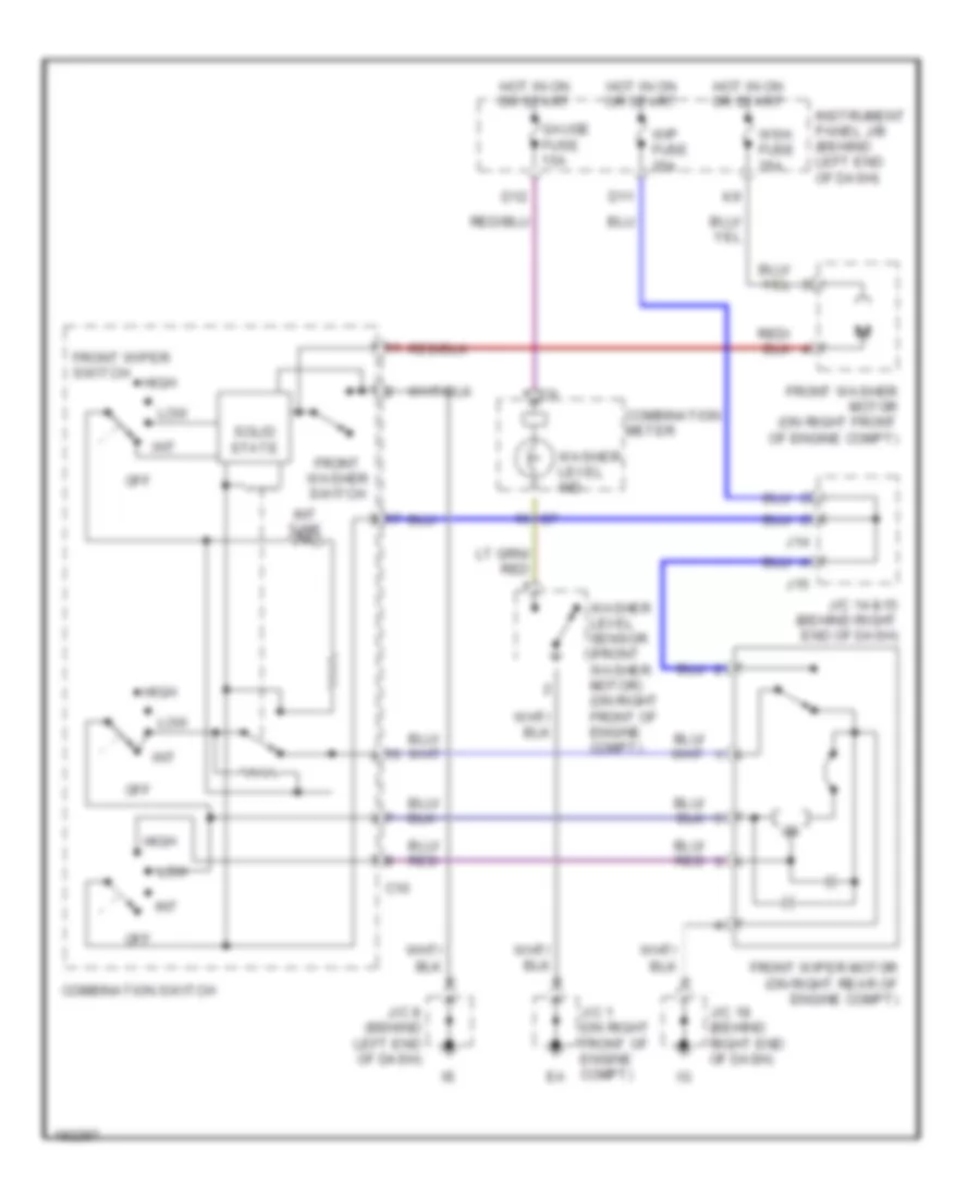
DEFOGGERS
Defoggers Wiring Diagram for Toyota Sequoia SR5 2004
List of elements for Defoggers Wiring Diagram for Toyota Sequoia SR5 2004:
- A10
- C10
- Defog fuse 40a
- Defog relay
- Engine room j/b (on left side of engine compt)
- Fusible link block (in engine room j/b)
- Hot at all times
- Hot in on or start
- Htr fuse 10a
- Instrument panel j/b (behind left end of dash)
- J35
- J36
- Junction connector 18 (behind right end of dash)
- Junction connector 19 (on left rear of cargo area, behind trim panel)
- Junction connector 28 (near engine room j/b)
- Junction connector 3 (on left side of engine compt, near engine room j/b)
- Junction connector 35 & 36 (left end j36 of dash)
- Junction connector 6 & 7 (behind left kick panel)
- Junction connector 8 (behind left end of dash)
- K12
- Left mirror heater (left remote control mirror)
- Mir htr fuse 15a
- Mirror heater relay (behind left end of dash, beside instrument panel j/b)
- R14
- R15
- Rear window defogger
- Rear window defogger switch (integration control & panel)
- Right mirror heater (right remote control mirror)
- Sub j/b 4 (behind right side of instrument cluster)
- W/ retractor
- W/o retractor
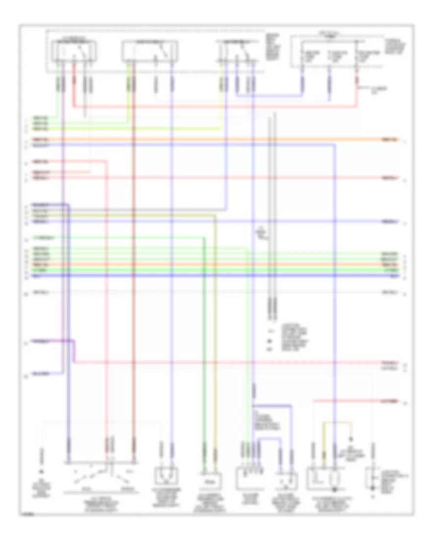
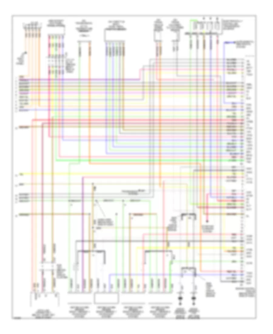
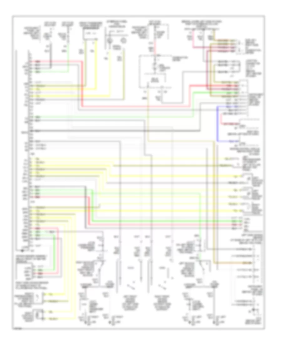
ENGINE PERFORMANCE
4.7L
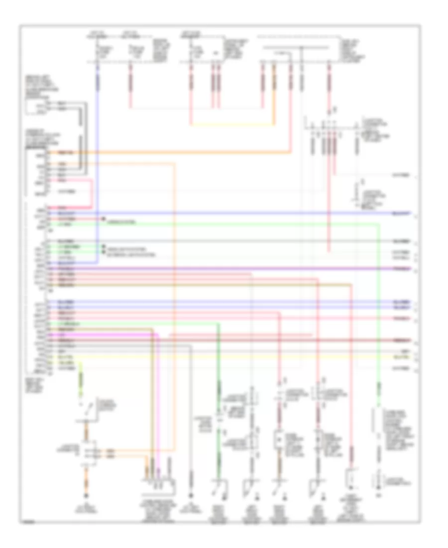
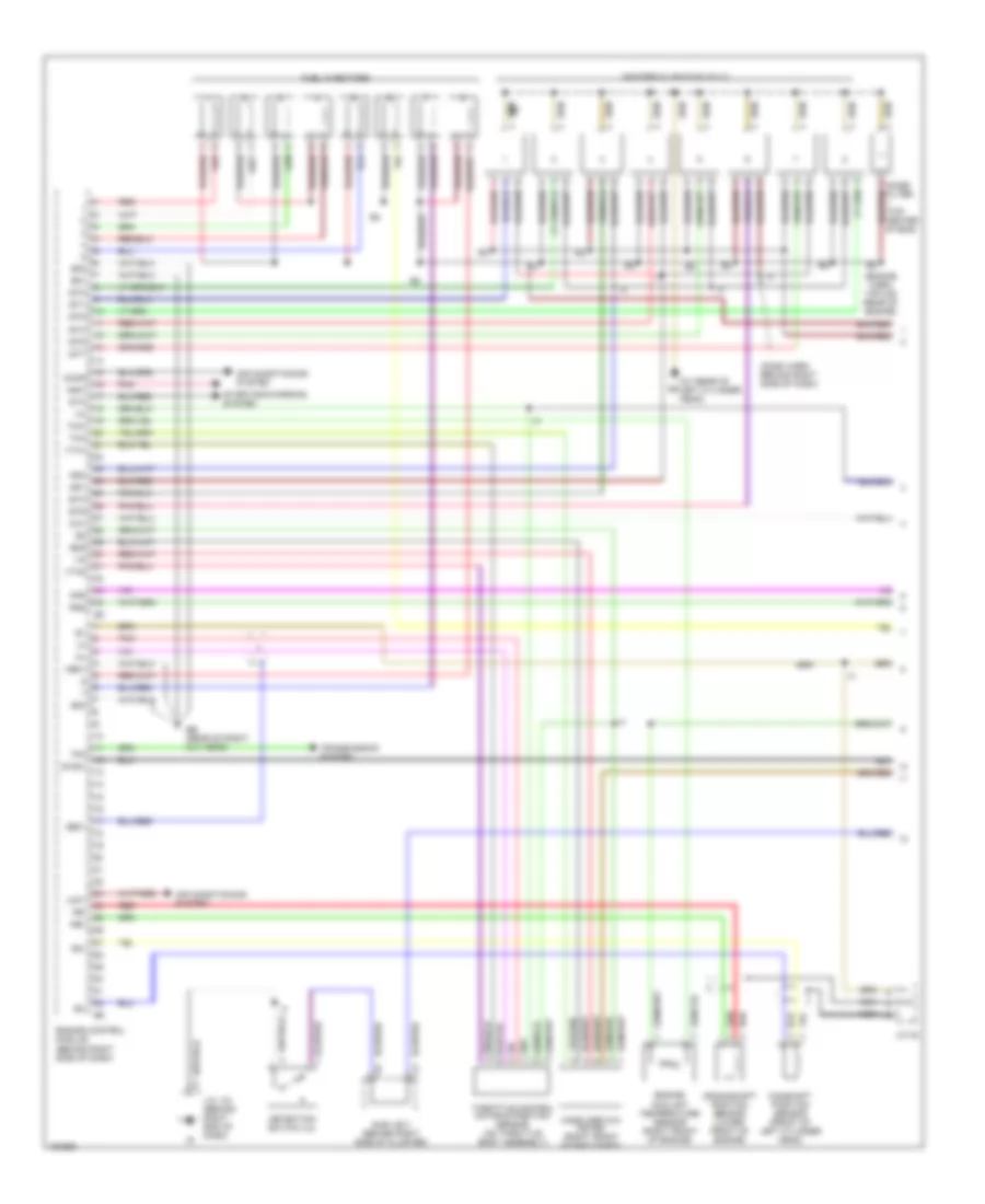
4.7L, Engine Performance Wiring Diagram (1 of 4) for Toyota Sequoia SR5 2004
List of elements for 4.7L, Engine Performance Wiring Diagram (1 of 4) for Toyota Sequoia SR5 2004:
- (at rear of left cylinder head)
- (dash harn behind right side of dash)
- (engine harn, top mid rear of engine)
- Accr
- Air conditioning system
- Camshaft position sensor (front of left cylinder head)
- Ccv
- Crankshaft position sensor (lower front of engine)
- Detection switch (l4)
- E01
- E02
- E03
- E2g
- Eb (rear of right cly head)
- Engine control module (behind right side of dash)
- Engine coolant temperature sensor (right front of engine)
- Fpr
- Fuel injectors
- G2+
- G2-
- Ge01
- Igf1
- Igf2
- Igniters & ignition coils
- Igt1
- Igt2
- Igt3
- Igt4
- Igt5
- Igt6
- Igt7
- Igt8
- J/c 42
- J/c j18 (behind right end of dash)
- Lck1
- Mass airflow meter (right front of eng compt)
- Me01
- Nca
- Ne+
- Ne-
- Nsw
- Pnk
- Prg
- Red
- Sta
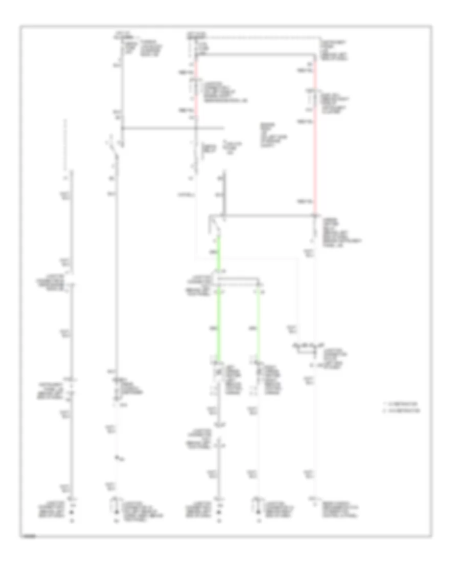
- Starting/charging system
- Stsw
- Sub j/b 3 (behind right side of cluster)
- Tfn
- Tha
- Throttle control motor & position sensor (on throttle body assembly)
- Thw
- Transmission system
- Vta1
- Vta2
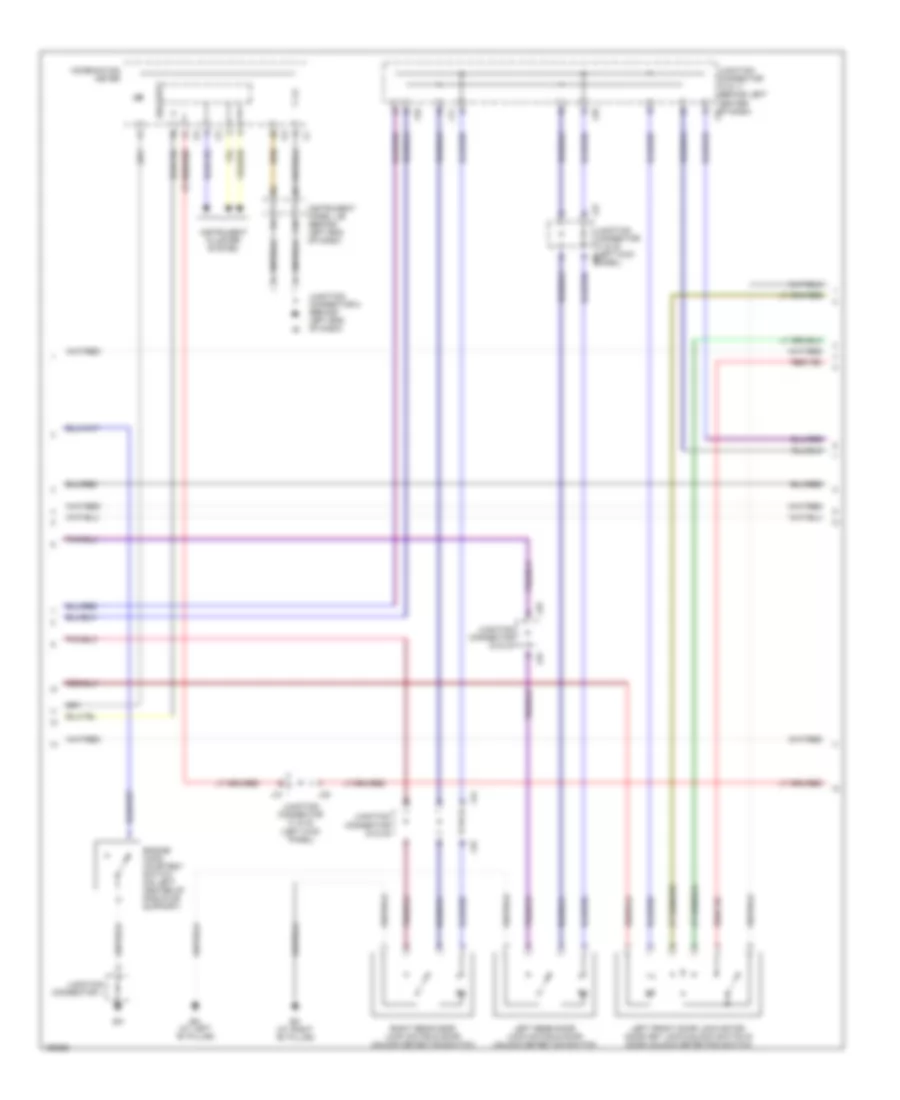
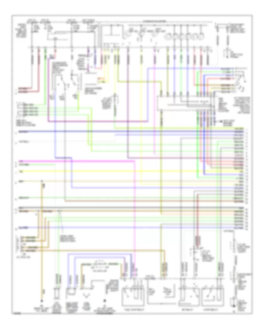
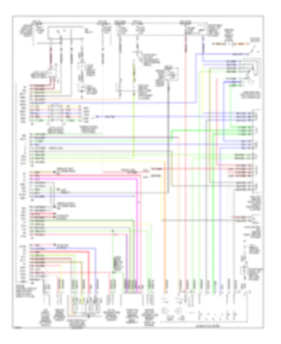
4.7L, Engine Performance Wiring Diagram (2 of 4) for Toyota Sequoia SR5 2004
List of elements for 4.7L, Engine Performance Wiring Diagram (2 of 4) for Toyota Sequoia SR5 2004:
- (dash harn behind right side of dash)
- (on bracket, above brake pedal) stoplight switch
- A/t indicator light switch (integral to park/neutral position switch) (on trans)
- A/t oil temp
- Anti-lock brakes system
- Bi (at left side of room partition crossmember)
- C/opn relay
- C10
- Combination meter
- D10
- D12
- E18
- Ec (rear of left cyl head)
- Efi 1 fuse 20a
- Efi 2 fuse 10a
- Efi relay
- Engine room j/b (left side of engine compt)
- F10
- Fuel pump (in fuel tank)
- Fuel pump relay
- Fuel pump resistor (left rear of engine compt)
- Gauge fuse 10a
- Hot at all times
- Hot in run or start
- Ie (left kick panel)
- Ign2 fuse 20a
- Instru- ment panel j/b (behind left end of dash)
- Instrument panel j/b (behind left end of dash)
- Ipo
- J/c 35 (right end of dash)
- J/c j14 & j15 (behind right end of dash)
- J/c j28 (left side of eng compt)
- J/c j28 (on left side of engine compt)
- J/c j35 & j36
- J/c j48 & j49
- J/c j8 (behind left end of dash)
- J14
- J15
- J35
- J36
- J48
- J49
- Malf ind lamp
- O/d off ind
- Stop fuse 15a
- Sub j/b 3 (behind right side of cluster)
- Sub j/b 4 (behind right side of cluster)
- Tail fuse 15a
- Vehicle speed sensor (on trans)
- Vsv (evap) (top left side of engine)
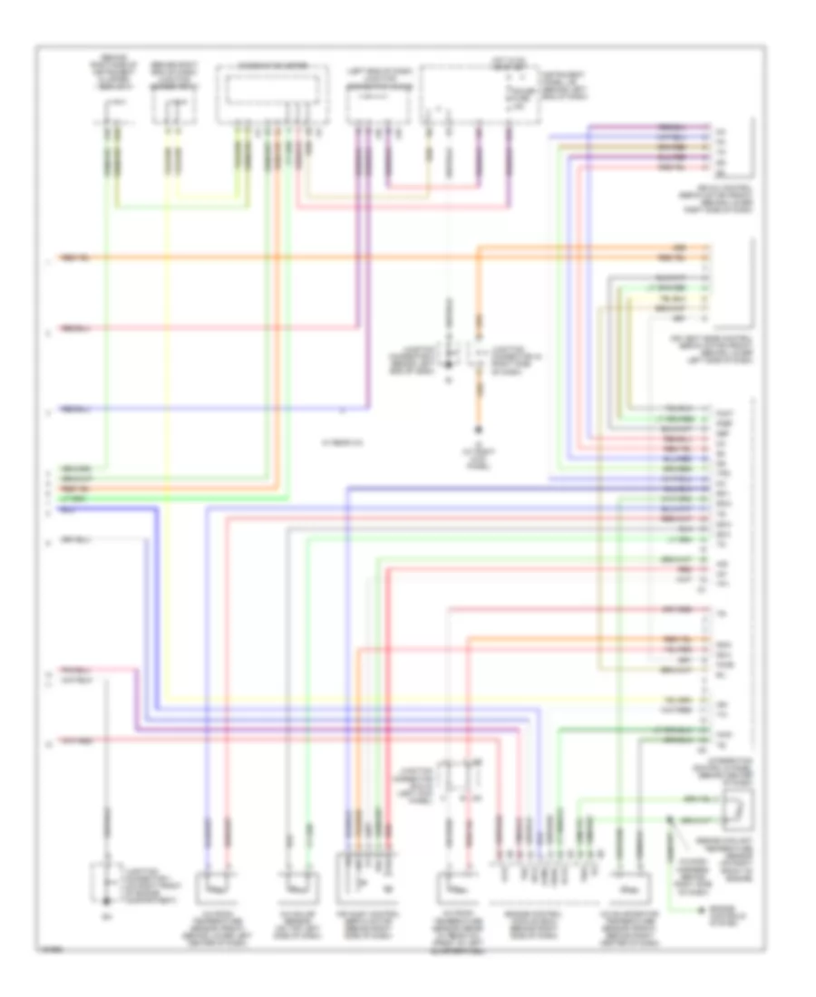
4.7L, Engine Performance Wiring Diagram (3 of 4) for Toyota Sequoia SR5 2004
List of elements for 4.7L, Engine Performance Wiring Diagram (3 of 4) for Toyota Sequoia SR5 2004:
- (dash harn behind right side of dash)
- (left rear of engine compt) vsv (canister closed valve)
- (under rear of vehicle) vapor pressure sensor
- (under rear of vehicle) vsv (pressure switching valve)
- +bm
- 2wd
- 4wd
- 4wd control ecu (behind center of dash)
- A/cs
- Acld
- Acmg
- Air conditioning system
- Ccs
- Cruise control
- E17
- Engine control module (behind right side of dash)
- Engine room j/b (left side of engine compt)
- Engine room r/b 2 (left side of engine compt)
- Etcs fuse 15a
- F11
- Hot in run or start
- Hot in start
- Ign 1 fuse 10a
- Imi
- Imo
- Instrument panel j/b (behind left end of dash)
- J/c j46 & j47
- J/c j48 & j49
- J/e j44 & j45
- J/e j48 & j49
- J44
- J45
- J46
- J47
- J48
- J49
- J49 e
- O/d main switch
- Odlp
- Oilw
- Spd
- St1-
- Sta fuse 7.5a
- Stp
- Sub j/b 4 (behind right side of cluster)
- System
- System anti-theft
- The
- Thwo
- W/ 4wd
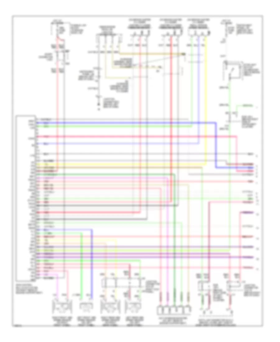
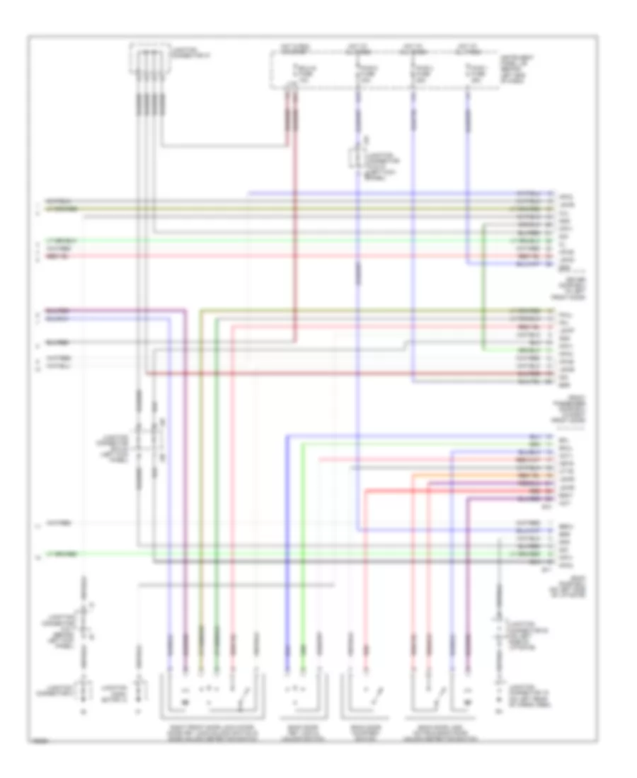
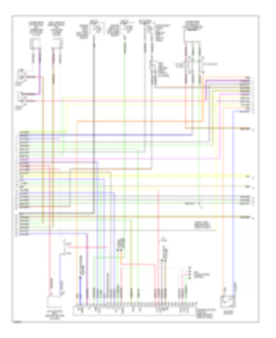
4.7L, Engine Performance Wiring Diagram (4 of 4) for Toyota Sequoia SR5 2004
List of elements for 4.7L, Engine Performance Wiring Diagram (4 of 4) for Toyota Sequoia SR5 2004:
- (above right kick panel) translate ecu
- (dash harn behind right side of dash)
- (eng harn, top middle rear of engine)
- (on throttle body) accel pedal position sensor
- (on trans) o/d direct clutch speed sensor
- (on trans) vehicle speed sensor
- (on transmission)
- +b2
- 4wd
- A/t oil temperature sensor
- A17
- Batt
- Data link connector 3 (below lower left side of dash)
- Electronically controlled transmission solenoid
- Els
- Eng+
- Eng-
- Engine control module (behind right side of dash)
- Eom
- Epa
- Epa2
- F/ps
- Heated oxygen sensor (bank 1 sensor 1) (on exhaust system)
- Heated oxygen sensor (bank 1 sensor 2) (on exhaust system)
- Heated oxygen sensor (bank 2 sensor 1) (on exhaust system)
- Heated oxygen sensor (bank 2 sensor 2) (on exhaust system)
- Ht1a
- Ht1b
- Ht2a
- Ht2b
- Ig (at right kick panel)
- Igsw
- J/c j14 & j15 (behind right end of dash)
- J/c j43
- J14
- J15
- Knk1
- Knk2
- Knock sensor 1 (top right side of engine)
- Knock sensor 2 (top left side of engine)
- Mrel
- Nca
- Nco+
- Nco-
- Neo
- Odms
- Ox1a
- Ox1b
- Ox2a
- Ox2b
- Pnk
- Ptnk
- Red
- Sil
- Slt
- Slt+
- Slt-
- Sp2+
- Sp2-
- Star
- Starting/ charging system
- Sub j/b 4 (behind right side of cluster)
- Tach
- Tbp
- Thoc
- Transmission system
- Trc+
- Trc-
- Vcp2
- Vcpa
- Vpa
- Vpa2
- Wfse
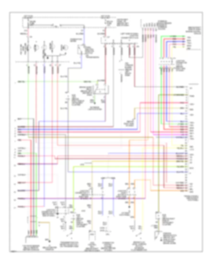
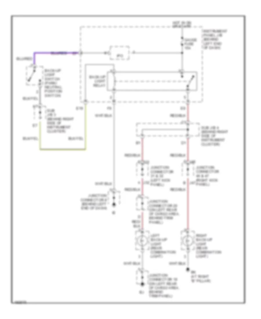
EXTERIOR LIGHTS
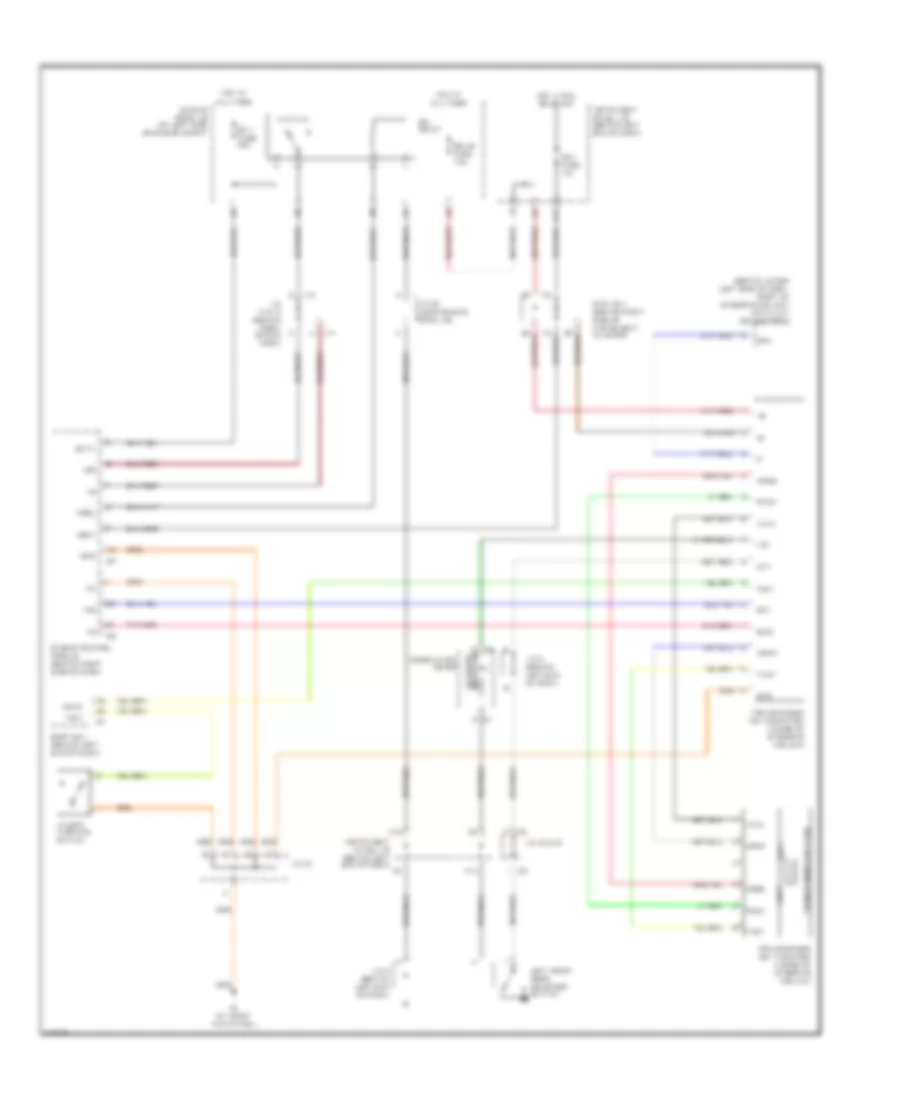
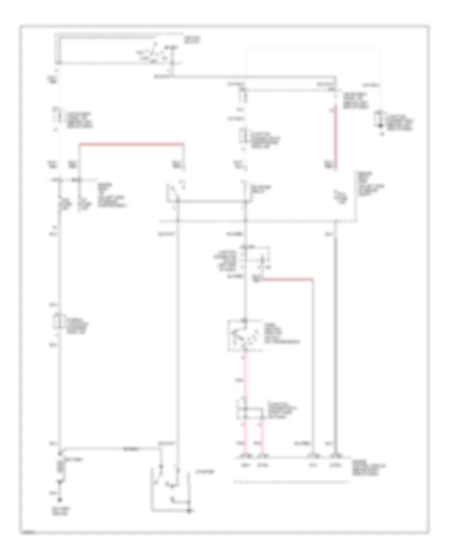
Back-up Lamps Wiring Diagram for Toyota Sequoia SR5 2004
List of elements for Back-up Lamps Wiring Diagram for Toyota Sequoia SR5 2004:
- Back-up light relay
- Back-up light switch (park/ neutral position switch)
- Bk (at right "b" pillar)
- E19
- Gauge fuse 15a
- Hot in on or start
- Instrument panel j/b (behind left end of dash)
- Ipo
- J31
- J46
- Junction connector 19 (on left rear of cargo area, behind trim panel)
- Junction connector 20 (on left rear of cargo area, behind trim panel)
- Junction connector 31 & 32 (left kick j32 panel)
- Junction connector 46 & 47 (right kick j47 panel)
- Junction connector 8 (behind left end of dash)
- Left back-up light (rear combination light)
- Right back-up light (rear combination light)
- Sub j/b 3 (behind right side of instrument cluster)
- Sub j/b 4 (behind right side of instrument cluster)
Exterior Lamps Wiring Diagram for Toyota Sequoia SR5 2004
List of elements for Exterior Lamps Wiring Diagram for Toyota Sequoia SR5 2004:
- (combi- nation switch) turn signal switch
- (left end of dash) junction connector 35 & 36
- (w/ rear spoiler)
- (w/o rear spoiler)
- A j48
- Alt fuse 140a
- Bk (at right "b" pillar)
- Body ecu (behind left end of dash)
- Brake inhibit relay (behind left center of dash)
- Combination meter
- E j30
- E11
- E18
- Ecu-ig fuse 10a
- Ehw
- Engine room j/b (on left side of engine compt)
- F10
- Fusible link block (in engine room j/b)
- Gauge fuse 15a
- Gnd
- Hazard switch (integration control & panel)
- Head
- High mounted stop light
- Hot at all times
- Hot in on or start
- Instrument panel j/b (behind left end of dash)
- J/c 29 & (left kick panel)
- J/c 8 (behind left end of dash)
- J29
- J33 j/c 33 & (left kick j34 panel)
- J35
- J36
- J37 a
- J38 a
- J44
- J44 f
- J45 m
- J49 g
- Junction connector 1 (on right front of engine compt)
- Junction connector 12 (behind left center of dash)
- Junction connector 16 (behind right end of dash)
- Junction connector 19 (on left rear of cargo area, behind trim panel)
- Junction connector 2 (on left side of engine compt, near engine room j/b)
- Junction connector 20 (on left rear of cargo area, behind trim panel)
- Junction connector 21 (on left rear of cargo area, behind trim panel)
- Junction connector 22 (on left side of liftgate)
- Junction connector 29 & 30 (left kick panel)
- Junction connector 3 (on left side of engine compt, near engine room j/b)
- Junction connector 35 & 36 (left end of dash) j36
- Junction connector 37 & 38 (left side of dash)
- Junction connector 4 (on left side of engine b compt, near engine room j/b)
- Junction connector 44 & 45 (right kick panel)
- Junction connector 48 & 49 (right kick panel)
- Junction connector 5 (on left side of engine compt, near engine room j/b)
- Junction connector 8 (behind left end of dash)
- Junction connector 9 (behind left end of dash)
- L j29
- Left front park/ turn light 1
- Left front park/ turn light 2
- Left rear combin- ation light
- Left tail- light
- License plate light
- Light control switch (combination switch)
- M j30
- Off
- Park
- Right front park/ turn light 1
- Right front park/ turn light 2
- Right rear combin- ation light
- Right tail- light
- Skid control ecu w/ actuator (on right rear of engine compt)
- Stop
- Stop fuse 15a
- Stoplight switch (on bracket, above brake pedal)
- Sub j/b 4 (behind right side of instrument cluster)
- Tail
- Tail fuse 15a
- Taillight relay
- Trly
- Turn
- Turn signal flasher relay (behind left end of dash, below instrument panel j/b)
- Turn signal indicator lights
- Turn- haz fuse 20a
Trailer Tow Wiring Diagram for Toyota Sequoia SR5 2004
List of elements for Trailer Tow Wiring Diagram for Toyota Sequoia SR5 2004:
- (trailer socket 7 pin type) back-up light relay
- (trailer socket 7 pin type) batt charge relay
- 4 pin type
- 7 pin type
- A j32
- B/up
- Back-up lamps circuit
- Batt
- Batt charge fuse 30a
- Bj (at left side of rear quarterpanel)
- Body ecu (behind left end of dash)
- Brake inhibit relay (behind left center of dash)
- Brk
- Bsw
- E18
- E19
- Ecu-ig fuse 10a
- Engine room j/b (on left side of engine compt)
- Engine room r/b 3 (on left side of engine compt)
- Gauge fuse 15a
- Gnd
- Hot at all times
- Hot in on or start
- Ig (at right kick panel)
- Instrument panel j/b (behind left end of dash)
- Ipo
- J/c 16 (behind right end of dash)
- J/c 19 (on left rear of cargo area, behind trim panel)
- J/c 20 (on left rear of cargo area, behind trim panel)
- J/c 28 (near engine room j/b)
- J/c 29 & (left kick panel)
- J/c 31 & 32 (left kick panel)
- J/c 33 & 34 (left kick panel)
- J/c 35 & 36 (left end of dash)
- J/c 37 & (left side of dash)
- J/c 43 (right side of dash)
- J/c 9 (behind left end of dash)
- J29
- J30 e
- J31
- J33
- J35
- J36 d
- J36 e
- J37
- J38
- K12
- Ltin
- Ltot
- Red
- Rtin
- Rtot
- Skid control ecu w/ actuator (on right rear of engine compartment)
- Stin
- Stop
- Stop fuse 15a
- Stoplight switch (on bracket above brake pedal)
- Sttl
- Sttr
- Sub j/b 4 (behind right side of instrument cluster)
- Tail
- Tail fuse 15a
- Towing brake controller (trailer socket 7 pin type) (at left kick panel)
- Towing brk fuse 30a
- Towing converter relay (on left side of cargo area, behind trim panel)
- Towing fuse 30a
- Towing tail fuse 30a
- Towing tail relay
- Trailer socket
- Trly
- Turn signal flasher relay (behind left end of dash, below instrument panel j/b)
- Turn- haz fuse 20a
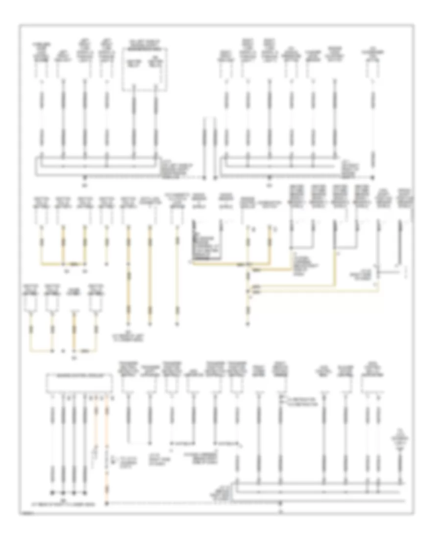
GROUND DISTRIBUTION
Ground Distribution Wiring Diagram (1 of 3) for Toyota Sequoia SR5 2004
List of elements for Ground Distribution Wiring Diagram (1 of 3) for Toyota Sequoia SR5 2004:
- (diagram
- (on left side of engine compt) engine room r/b 2
- (right side
- 2 of 3)
- 4wd control ecu
- A/c condenser fan motor
- A/c magnetic clutch & lock sensor
- A/c single pressure switch
- Add actuator
- Blower motor control
- Cam- shaft position sensor shield
- Combination switch
- Crank- shaft position sensor shield
- Data link connector
- E2 nca (in engine engine harness, at top center rear of engine)
- Eb (at rear of right cylinder head)
- Ec (at rear of left cylinder head)
- Engine control module
- Engine hood courtesy switch
- Front wiper motor
- Heated oxygen sensor (bank 1 sensor 1) shield
- Heated oxygen sensor (bank 1 sensor 2) shield
- Heated oxygen sensor (bank 2 sensor 1) shield
- Heated oxygen sensor (bank 2 sensor 2) shield
- Heater relay
- I4 (in dash harness, behind right side of dash)
- Ignition coil & igniter 1
- Ignition coil & igniter 2
- Ignition coil & igniter 3
- Ignition coil & igniter 4
- Ignition coil & igniter 5
- Ignition coil & igniter 6
- Ignition coil & igniter 7
- Ignition coil & igniter 8
- J/c 1 (on right front of engine compt)
- J/c 18 (behind right end of dash)
- J/c 42 (right side of dash)
- J/c 43
- J/c 5 (on left side of engine compt, near engine room j/b)
- Knock sensor shield
- Left front foglight
- Left front turn signal & parking light 1
- Left front turn signal & parking light 2
- Nca
- Noise filter 1
- Of dash)
- Right front foglight
- Right front turn signal & parking light 1
- Right front turn signal & parking light 2
- Right remote control mirror
- Rr heater relay
- Skid control ecu w/ actuator
- To j/c 43
- To j/c 8 (diagram 2 of 3)
- Transfer neutral detection switch
- Transfer position detection switch 1
- Transfer position detection switch 2
- Transfer position detection switch l4
- Transfer shift actuator
- W/ retractor
- W/o retractor
- Washer level sensor
- Wireless door lock control buzzer
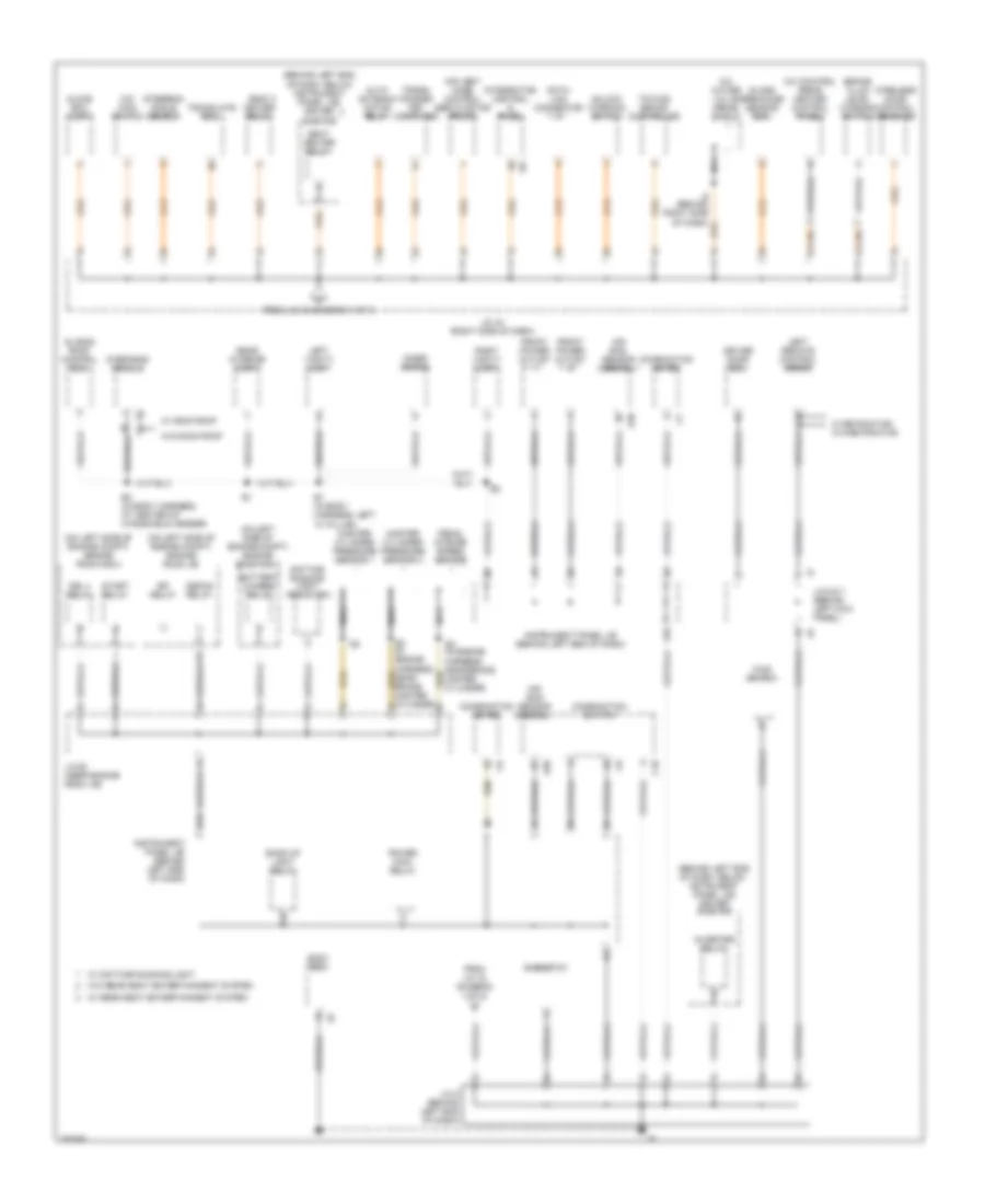
Ground Distribution Wiring Diagram (2 of 3) for Toyota Sequoia SR5 2004
List of elements for Ground Distribution Wiring Diagram (2 of 3) for Toyota Sequoia SR5 2004:
- (behind left end of dash, below nstrument panel j/b) driver side r/b
- (behind left end of dash, below instrument panel j/b) driver side r/b
- (in engine harness, near brake master cylinder)
- (on left side of engine compt) engine room j/b
- (on left side of engine compt) engine room r/b 2
- (on left side of engine compt) engine room r/b 3
- A/c control (rear heater control panel)
- A/c water valve (rear) shield
- A20
- Air bag sensor assembly
- Air vent mode control servo motor (front)
- Auto antenna motor relay
- B1 (in body harness, left "a" pillar)
- B2 (in body harness, at center of windshield header)
- Back-up light relay
- Battery charge relay
- Body ecu
- Brake fluid level warning switch
- C10
- Combination meter
- Combination switch
- Data link connector
- Daytime running light resistor
- Defog relay
- Driver door ecu
- Drl 4 relay
- Efi relay
- F10
- From j/c 18 (diagram 1 of 3)
- From j/c 43 (diagram 1 of 3)
- Front power outlet
- Glass breakage sensor ecu
- Glove box light
- I19
- Inner mirror
- Instrument panel j/b (behind left end of dash)
- Integration control & panel
- Inverter relay
- J/c 28 (near engine room j/b)
- J/c 43 (right side of dash)
- J/c 6 & 7 (behind left kick panel)
- J/c 8 (behind left end of dash)
- K12
- Left remote control mirror
- Left vanity light
- Main switch
- Master cylinder pressure sensor 1
- Master cylinder pressure sensor 2
- Nca
- O/d main switch
- Overhead module
- Pedal stroke speed sensor
- Power main relay
- Rear interior light
- Rheostat
- Right vanity light
- Seat heater relay
- Sliding roof control ecu
- Start relay
- Steering angle sensor
- Towing brake controller
- Trans- ponder key computer
- Translate ecu
- Unlock warning switch
- W/ daytime running light
- W/ moon roof
- W/ rear seat entertainment system
- W/ retractor w/o retractor
- W/o moon roof
- W/o rear seat entertainment system
- Wireless door control receiver
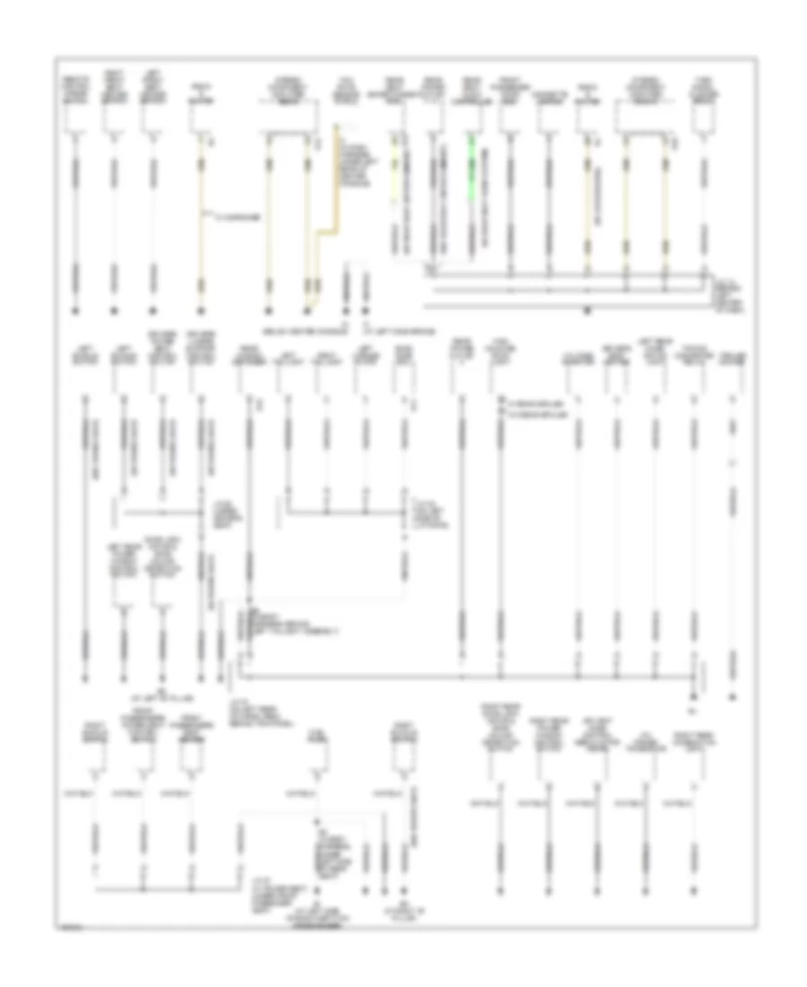
Ground Distribution Wiring Diagram (3 of 3) for Toyota Sequoia SR5 2004
List of elements for Ground Distribution Wiring Diagram (3 of 3) for Toyota Sequoia SR5 2004:
- (w/ 10 speakers)
- (w/ power seat)
- (w/ rear seat audio system)
- (w/ rear seat entertainment)
- (w/o power seat)
- (w/o rear seat entertainment)
- A/c power transistor
- Air vent mode control servo motor (rear)
- B11
- B3 (in body harness, under left side of rear seat)
- Back door ecu
- Bh (at left "b" pillar)
- Bi (at left side of room partition crossmember)
- Bk (at right "b" pillar)
- Cigarette lighter
- Door lock motor & door unlock detection switch
- Driver's lumbar support control switch
- Driver's power seat control switch
- Driver's seat heater
- Front passenger door ecu
- Front passenger's power seat control switch
- Front passenger's seat heater
- Fuel pump
- High mounted stop- light
- I3 (in dash harness, under left rear of center console)
- If (at left dash brace)
- Im (below center console)
- J/c 12 (behind left center of dash)
- J/c 19 (on left rear of cargo area, behind trim panel)
- J/c 22 (on left side of liftgate)
- J/c 25 (under driver's seat)
- J/c 27 (w/ power seat) (under front passenger seat)
- Left buckle switch
- Left front seat heater switch
- Left license plate
- Left rear combi- nation light
- Left rear power window control switch
- Left taillight
- R15
- R22
- Radio & player
- Rear power outlet
- Rear seat audio controller
- Rear seat entertainment ecu
- Rear window defogger
- Remote control mirror switch
- Right buckle switch
- Right front seat heater switch
- Right rear combination light
- Right rear door lock motor & door unlock detection switch
- Right rear power window control switch
- Right taillight
- S10
- S12
- Stereo component amplifier (front)
- Stereo component amplifier (rear)
- Towing converter relay
- Trailer socket
- Turn signal flasher relay
- Voltage inverter
- W/ 6 speaker
- W/ rear spoiler
- W/o rear spoiler
- Yaw rate sensor shield
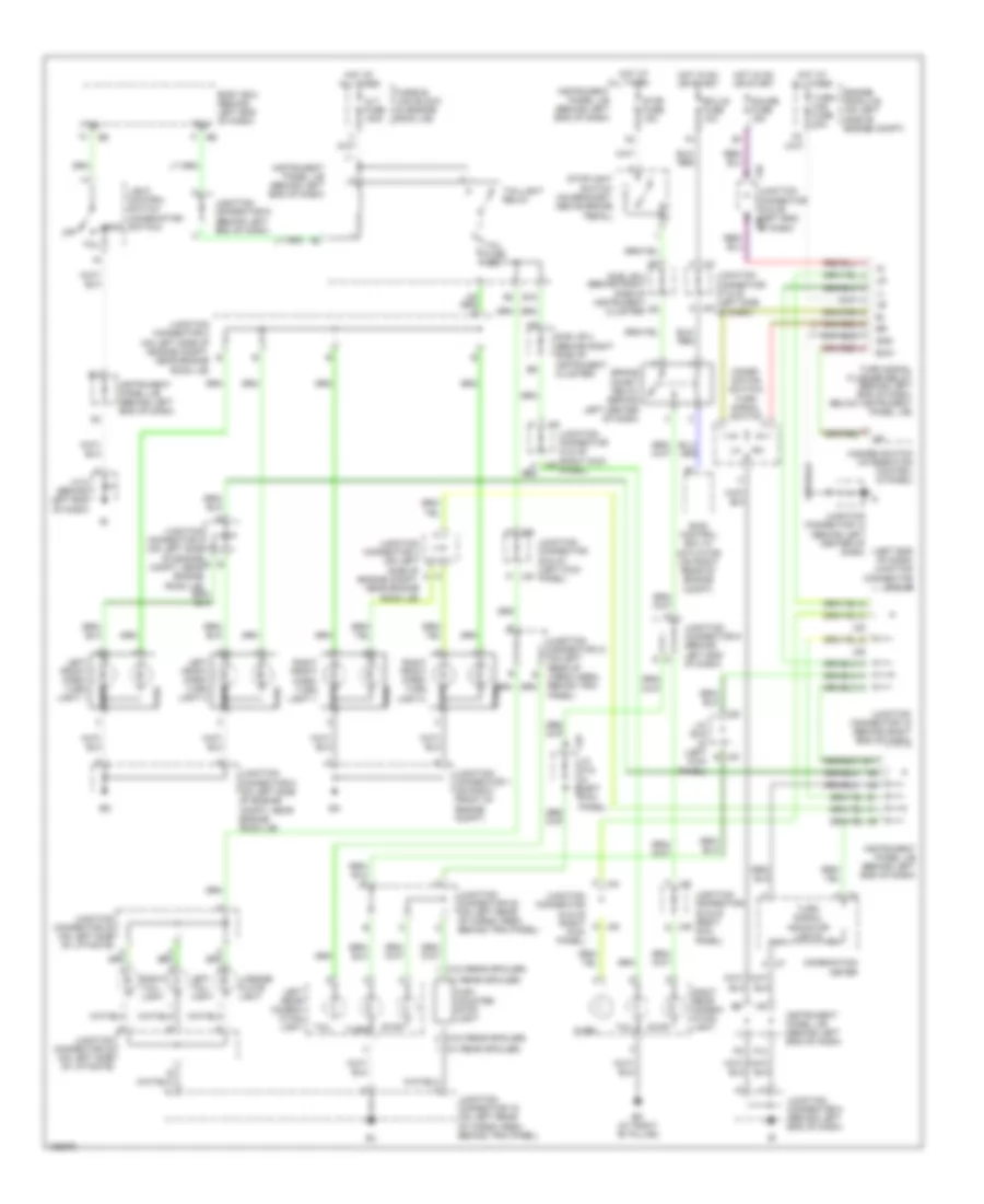
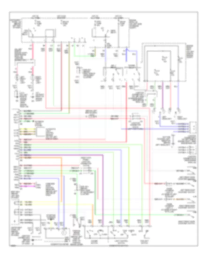
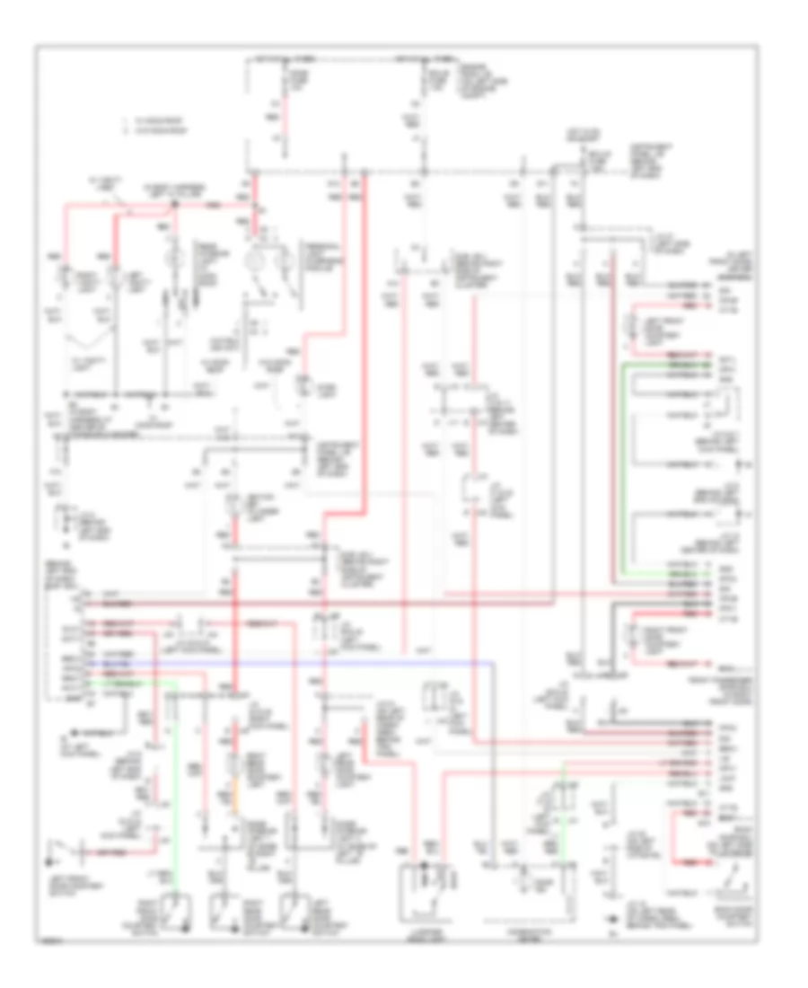
HEADLIGHTS
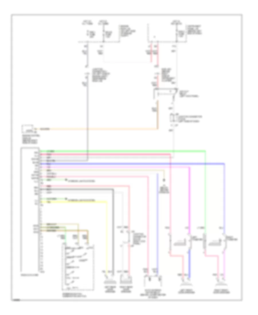
Headlights Wiring Diagram, with DRL for Toyota Sequoia SR5 2004
List of elements for Headlights Wiring Diagram, with DRL for Toyota Sequoia SR5 2004:
- (behind left end of dash) j/c 9
- (on left side of engine compt, near engine room j/b) junction connector 3
- (right kick panel) junction connector 44 & 45
- A13
- Auto
- Automatic light control sensor (on top left side of dash)
- Becu
- Body ecu (behind left end of dash)
- Cltb
- Clte
- Clts
- Combination meter
- Combination switch
- Daytime running light resistor (behind left headlight)
- Dcty
- Dim
- Dimmer relay
- Dimmer switch
- Diode (interior light 1) (at base of right "b" pillar)
- Diode (interior light 2) (at base of left "b" pillar)
- Drl 4 relay
- Drl fuse 15a
- Ecu-b fuse 7.5a
- Ecu-ig fuse 10a
- Engine room j/b (on left side of engine compt)
- Engine room r/b 2 (on left side of engine compt)
- Exterior lights system
- F10
- Ffog
- Flash
- Fog fuse 15a
- Fog light relay
- Foglight switch
- G11
- H-lp lh 10a
- H-lp ll 10a
- H-lp rh 10a
- H-lp rl 10a
- H-on
- Head
- Head relay
- High
- High beam ind
- Hind
- Hot at all times
- Hot in on or start
- Hrly
- Instrument panel j/b (behind left end of dash)
- J/c 1 (on right front of engine compt)
- J/c 5 (on left side of engine compt, near engine room j/b)
- J10
- J33
- J34
- J44
- J45
- Junction connector 2 (on left side of engine compt, near engine room j/b)
- Junction connector 28 (near engine room j/b)
- Junction connector 33 & 34 (left kick panel)
- Junction connector 4 (on left side of engine compt, near engine room j/b)
- Junction connector 8 (behind left end of dash)
- K12
- Left front door courtesy switch
- Left front fog light
- Left headlight
- Left rear door courtesy switch
- Light control switch
- Low
- Main fuse 40a
- Mpx2
- Off
- Parking brake switch (behind left side of dash, on parking brake lever)
- Pcty
- Pkb
- Pnk
- Prg
- Rda
- Red
- Right front door courtesy switch
- Right front fog light
- Right headlight
- Right rear door courtesy switch
- Rlcy
- Rrcy
- Starting/ charging system
- Sub j/b 4 (behind right side of instrument cluster)
- Tail
- Trly
- Wireless door control receiver (behind left center of dash)
Headlights Wiring Diagram, without DRL for Toyota Sequoia SR5 2004
List of elements for Headlights Wiring Diagram, without DRL for Toyota Sequoia SR5 2004:
- (left kick panel) junction connector 33 & 34
- (on left side of engine compt, near engine room j/b) junction connector 3
- A13
- Auto
- Automatic light control sensor (if equipped) (on top left side of dash)
- Becu
- Body ecu (behind left end of dash)
- Cltb
- Clte
- Clts
- Combination meter
- Combination switch
- Dcty
- Dimmer switch
- Diode (interior light 1) (at base of right "b" pillar)
- Diode (interior light 2) (at base of left "b" pillar)
- Ecu-b fuse 7.5a
- Ecu-ig fuse 10a
- Engine room j/b (on left side of engine compt)
- Exterior lights system
- F10
- Ffog
- Flash
- Fog fuse 15a
- Fog light relay
- Foglight switch
- G11
- H-lp (left) fuse 15a
- H-lp (right) fuse 15a
- Head
- Head relay
- High
- High beam ind
- Hot at all times
- Hot in on or start
- Hrly
- Instrument panel j/b (behind left end of dash)
- J/c 1 (on right front of engine compt)
- J/c 5 (on left side of engine compt, near engine room j/b)
- J10
- J33
- J34
- J44
- J45
- Junction connector 2 (on left side of engine compt, near engine room j/b)
- Junction connector 33 & 34 (left kick panel)
- Junction connector 4 (on left side of engine compt, near engine room j/b)
- Junction connector 44 & 45 (right kick panel)
- Junction connector 8 (behind left end of dash)
- Junction connector 9 (behind left end of dash)
- Left front door courtesy switch
- Left front fog light
- Left headlight
- Left rear door courtesy switch
- Light control
- Light control switch
- Low
- Main fuse 40a
- Off
- Parking brake switch (behind left side of dash, on parking brake lever)
- Pcty
- Pkb
- Pnk
- Prg
- Rda
- Right front door courtesy switch
- Right front fog light
- Right headlight
- Right rear door courtesy switch
- Rlcy
- Rrcy
- Sub j/b 4 (behind right side of instrument cluster)
- Tail
- Trly
- W/ automatic
- Wireless door control receiver (if equipped) (behind left center of dash)
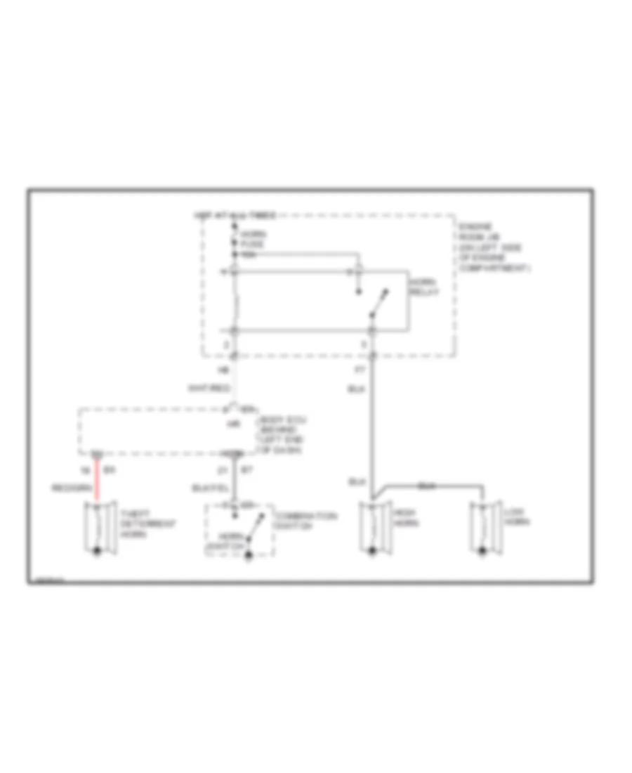
HORN
Horn Wiring Diagram for Toyota Sequoia SR5 2004
List of elements for Horn Wiring Diagram for Toyota Sequoia SR5 2004:
- Body ecu (behind left end of dash)
- Combination switch
- Engine room j/b (on left side of engine compartment)
- High horn
- Horn
- Horn fuse 10a
- Horn relay
- Horn switch
- Hot at all times
- Low horn
- Theft deterrent horn
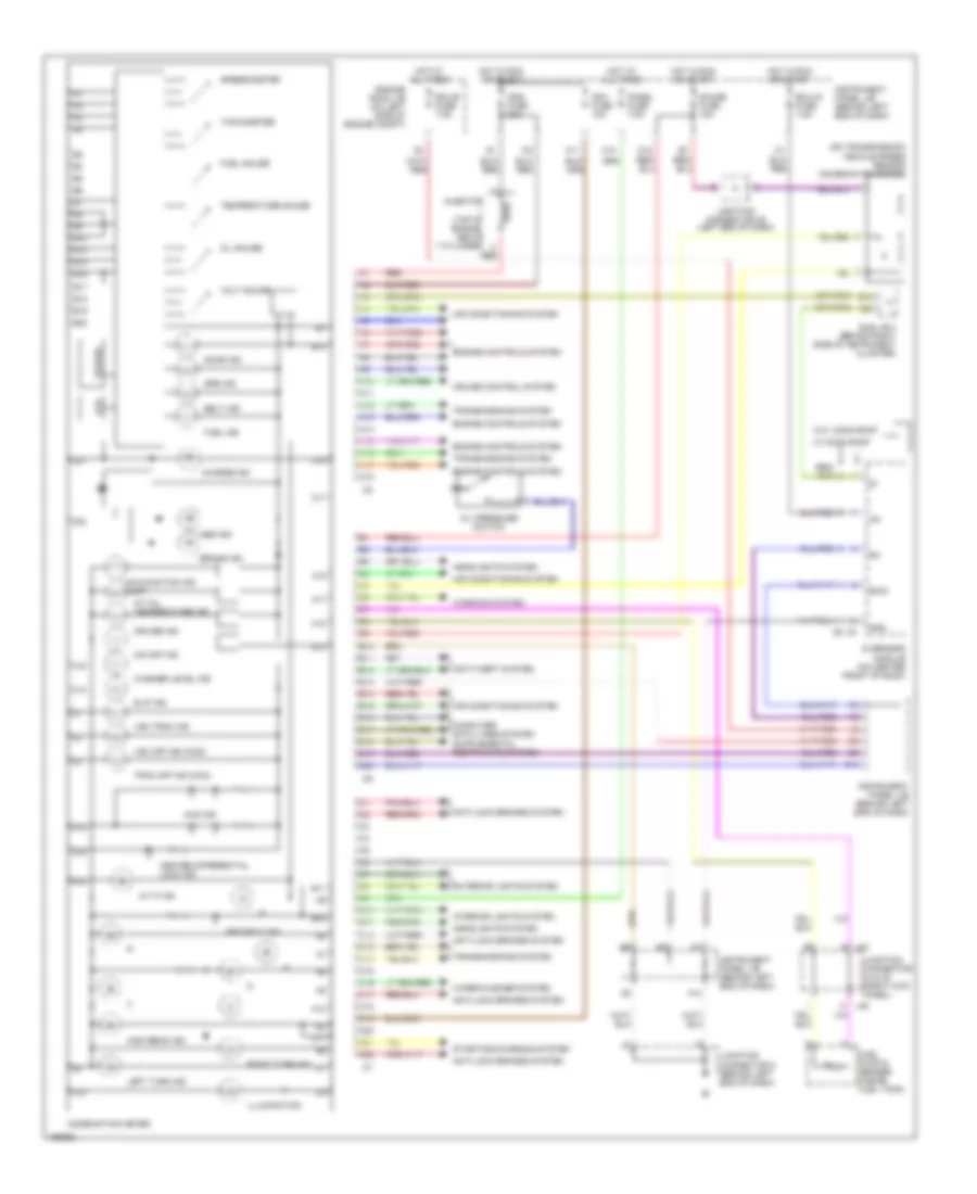
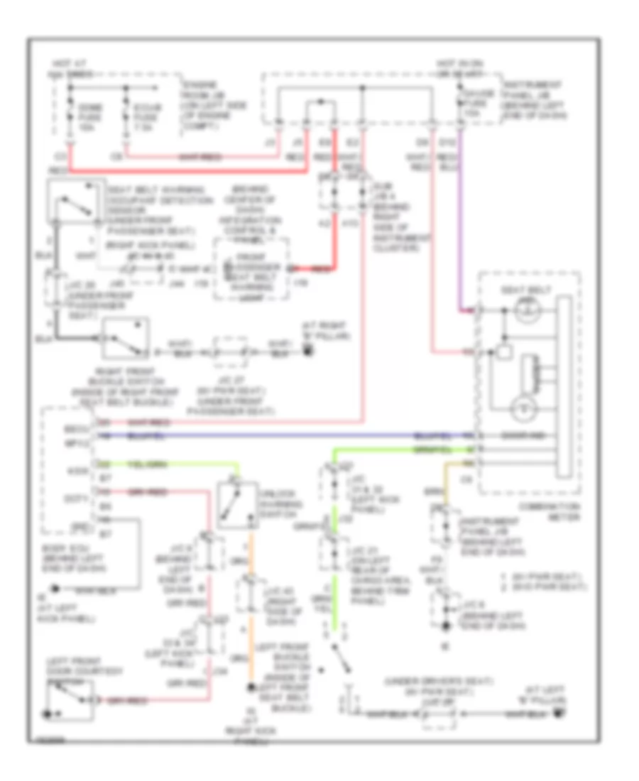
INSTRUMENT CLUSTER
Instrument Cluster Wiring Diagram for Toyota Sequoia SR5 2004
List of elements for Instrument Cluster Wiring Diagram for Toyota Sequoia SR5 2004:
- (on transmission) vehicle speed sensor (combination meter)
- 4wd ind
- A j44
- A/t oil temperature ind
- A/t p ind
- A10
- A11
- A12
- A13
- A14
- A15
- A16
- A17
- A18
- A20
- Abs ind
- Air conditioning system
- Anti-lock brakes system
- Anti-theft system
- B10
- B11
- B12
- B13
- B14
- B15
- B16
- B17
- B18
- B19
- B20
- Belt ind
- Brake ind
- Buzzer
- C10
- C11
- C12
- C13
- C14
- C15
- C16
- C17
- C18
- C19
- C20
- C21
- C22
- Center differential lock ind
- Charge ind
- Combination meter
- Computer data lines system
- Cruise control system
- Cruise ind
- D10
- D12
- Door ind
- E/mo
- Ecu-b fuse 7.5a
- Ecu-ig fuse 7.5a
- Engine controls system
- Engine room j/b (on left side of engine compt)
- Exterior lights system
- F10
- Fuel gauge
- Fuel ind
- Fuel pump & sender (inside fuel tank)
- Gauge fuse 15a
- Gnd
- H j45
- H10
- H11
- Headlights system
- High beam ind
- Hot at all times
- Hot in run or start
- Ig+
- Ign1 fuse 10a
- Ign2 fuse 20a
- Illumination
- Injector (top of engine, above 1 cylinder)
- Instrument panel j/b (behind left end of dash)
- Interior lights system
- Junction connector 44 & 45 (right kick panel)
- Junction connector 35 (left end of dash)
- Junction connector 8 (behind left end of dash)
- Lcd
- Left turn ind
- Malfunction ind lamp
- O/d off ind
- Oil gauge
- Oil pressure switch
- Overhead module (on center front of roof)
- Panel fuse 7.5a
- Red
- Right turn ind
- Security ind
- Slip ind
- Speedometer
- Srs ind
- Starting/charging system
- Sub j/b 3 (behind right side of instrument cluster)
- Tachometer
- Temperature gauge
- Trac off ind (2wd)
- Transmissions system
- Volt gauge
- Vsc off ind (4wd)
- Vsc trac ind
- W/ moon roof
- W/o moon roof
- Warning system
- Washer level ind
- Wiper/washer system
INTERIOR LIGHTS
Courtesy Lamps Wiring Diagram for Toyota Sequoia SR5 2004
List of elements for Courtesy Lamps Wiring Diagram for Toyota Sequoia SR5 2004:
- (behind left end of dash) body ecu
- (in body harness, left "a" pillar) b1
- (in left front door) driver door ecu
- A13
- B j32
- B10
- B11
- B2 (in body harness, at center of windshield header)
- Back door courtesy switch
- Back door ecu (on left side of liftgate)
- Bdcy
- Becu
- Combination meter
- Cpub
- Ctyb
- Ctye
- Dcty
- Dcyl
- Diode interior light 1 (at base of right ``b" pillar)
- Diode interior light 2 (at base of left ``b" pillar)
- Dome fuse 10a
- Door
- Door ind
- E j10
- Ecu-b fuse 7.5a
- Ecu-ig fuse 7.5a
- Engine room j/b (on left side of engine compt)
- F10
- Front passenger door ecu (in right front door)
- G11
- G13
- G14
- Gnd
- Hot at all times
- Hot in on or start
- Ie (at left kick panel)
- Ignition key cylinder light
- Ile
- Instrument panel j/b (behind left end of dash)
- J j34
- J/c 10 & 11 (behind left center of dash)
- J/c 12 (behind left center of dash)
- J/c 19 (on left rear of cargo area, behind trim panel)
- J/c 21 (on left rear of cargo area, behind trim panel)
- J/c 22 (on left side of liftgate)
- J/c 29 & 30 (left kick panel)
- J/c 31 & (left kick panel)
- J/c 31 & 32 (left kick panel)
- J/c 33 & (left kick panel)
- J/c 33 & 34 (left kick panel)
- J/c 37 (left side of dash)
- J/c 44 & 45 (right kick panel)
- J/c 6 & 7 (behind left kick panel)
- J/c 8 (behind left end of dash)
- J/c 9 (behind left end of dash)
- J10
- J11
- J29
- J30
- J30 l
- J31
- J32
- J33
- J34
- J44
- J45 b
- Left front door courtesy light
- Left front door courtesy switch
- Left rear door courtesy light
- Left rear door courtesy switch
- Left vanity light
- Lglp
- Luggage room light
- M10
- Mpx1
- Mpx2
- Off
- Pcty
- Pcyl
- Personal light (overhead module)
- Rear interior light (w/ moon roof)
- Red
- Right front door courtesy light
- Right front door courtesy switch
- Right rear door courtesy light
- Right rear door courtesy switch
- Right vanity light
- Rlcy
- Rrcy
- Sig
- Step light
- Sub j/b 4 (behind right side of instrument cluster)
- W/ moon roof
- W/ moon roof
- W/ vanity light
- W/o moon roof
Instrument Illumination Wiring Diagram for Toyota Sequoia SR5 2004
List of elements for Instrument Illumination Wiring Diagram for Toyota Sequoia SR5 2004:
- (left side of dash) j/c 39 & 40
- 10 spkr
- 6 spkr
- A j39
- A/c control (rear heater control panel)
- Alt fuse 140a
- Ashtray illum
- B j40
- Body ecu (behind left end of dash)
- Cigarette lighter illum
- Combination meter illumination (combination meter)
- E12
- E13
- Fusible link block (in engine room j/b)
- Glove box light
- H10
- Head
- Hot at all times
- Ig (at right kick panel)
- Ill-
- Instrument panel j/b (behind left end of dash)
- Integration control & panel (behind center of dash)
- J/c 39 & (left side of dash)
- J/c 43 (left side of dash)
- J/c 8 (behind left end of dash)
- J/c 9 (behind left end of dash)
- J39
- J40
- Left front seat heater switch
- Light control switch (combination switch)
- Main switch
- Off
- Overhead module (on center front of roof)
- Panel fuse 7.5a
- R19
- Radio & player
- Rheostat
- Right front seat heater switch
- Steering switch (combi- nation switch)
- Swg
- Tail
- Taillight relay
- Trly
- W/ moon roof
- W/o moon roof
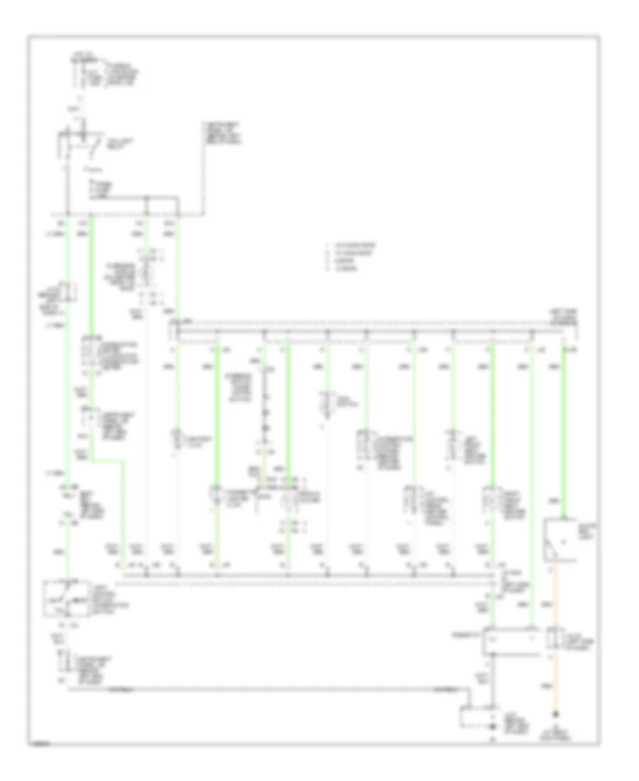
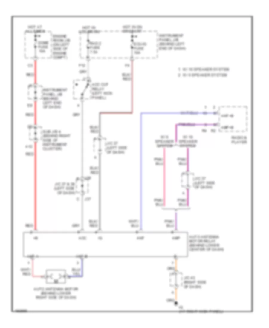
POWER ANTENNA
Power Antenna Wiring Diagram for Toyota Sequoia SR5 2004
List of elements for Power Antenna Wiring Diagram for Toyota Sequoia SR5 2004:
- A12
- Acc
- Acc cut relay (left kick panel)
- Amp
- Amp+b
- Ant
- Ant a
- Ant b
- Ant+b
- Auto antenna motor (behind lower right side of dash)
- Auto antenna motor relay (behind lower center of dash)
- Dome fuse 10a
- Ecu-ig fuse 10a
- Engine room j/b (on left side of engine compt)
- F12
- Hot at all times
- Hot in acc or on
- Hot in on or start
- Ig (at right kick panel)
- Instrument panel j/b (behind left end of dash)
- J/c 37 & 38 (left side of dash)
- J/c 37 (left side of dash)
- J/c 43 (right side of dash)
- J37
- J38
- Rad 2 fuse 7.5a
- Radio & player
- Red
- Sub j/b 4 (behind right side of instrument cluster)
- W/ 10 speaker system
- W/ 6 speaker system
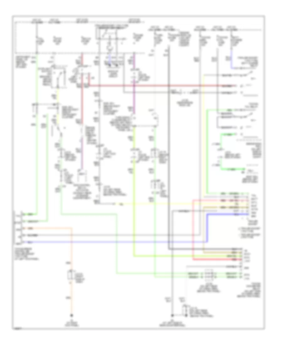
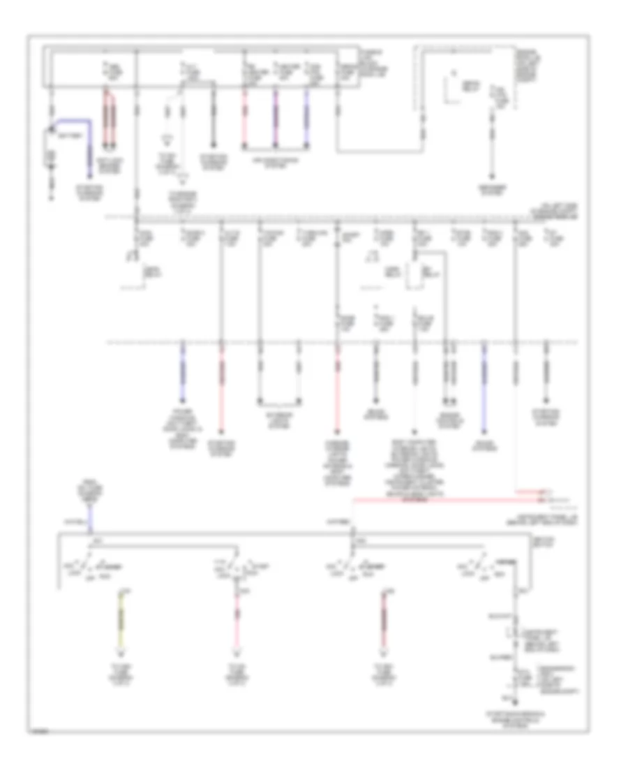
POWER DISTRIBUTION
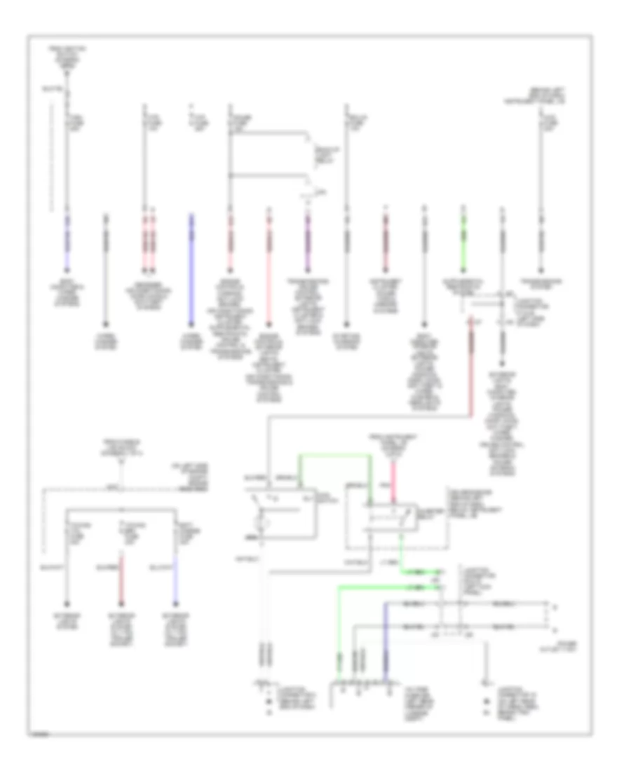
Power Distribution Wiring Diagram (1 of 3) for Toyota Sequoia SR5 2004
List of elements for Power Distribution Wiring Diagram (1 of 3) for Toyota Sequoia SR5 2004:
- (on left side of engine compt) engine room j/b
- Abs fuse 60a
- Acc
- Air conditioning system
- Alt fuse 140a
- Alt-s fuse 7.5a
- Am1
- Am2
- Am2 fuse 25a
- Anti-lock brakes system
- Battery
- Body computer, interior lights, exterior lights, power windows, warning, door locks, anti-theft, wiper/washer, instrument cluster, power antenna, sound & head lights systems
- Cds fan fuse 25a
- Defog fuse 40a
- Defog relay
- Defogger system
- Dome fuse 10a
- Door 2 fuse 30a
- Ecu-b fuse 7.5a
- Efi 1 fuse 20a
- Efi relay
- Engine controls system
- Engine room j/b (on left side of engine compt)
- Engine room r/b 2 (on left side of engine compt)
- Etcs fuse 10a
- Exterior lights system
- From am1 fuse (diagram 2 of 3)
- Fusible link block (in engine room j/b)
- Head relay
- Heater fuse 40a
- Horn fuse 10a
- Horn relay
- Ig1
- Ig2
- Ignition switch
- Instrument panel j/b (behind left end of dash)
- Lock
- Main fuse 40a
- Mir htr fuse 15a
- Nca
- Off
- Pnk
- Power windows, anti-theft, door locks, & body computer systems
- Rad 1 fuse 25a
- Rad 3 fuse 20a
- Red
- Rr heater fuse 30a
- Run
- Short pin
- Sound systems
- St fuse 30a
- St2
- Sta fuse 7.5a
- Start
- Starting/ charging system
- Starting/charging & engine controls systems
- To am1 fuse (diagram 2 of 3)
- To cig fuse (diagram 2 of 3)
- To engine room r/b 3 (diagram 3 of 3)
- To ign1 fuse (diagram 2 of 3)
- To wsh fuse (diagram 3 of 3)
- Towing fuse 30a
- Turn-haz fuse 20a
- Warning, interior lights, power antenna & body computer systems
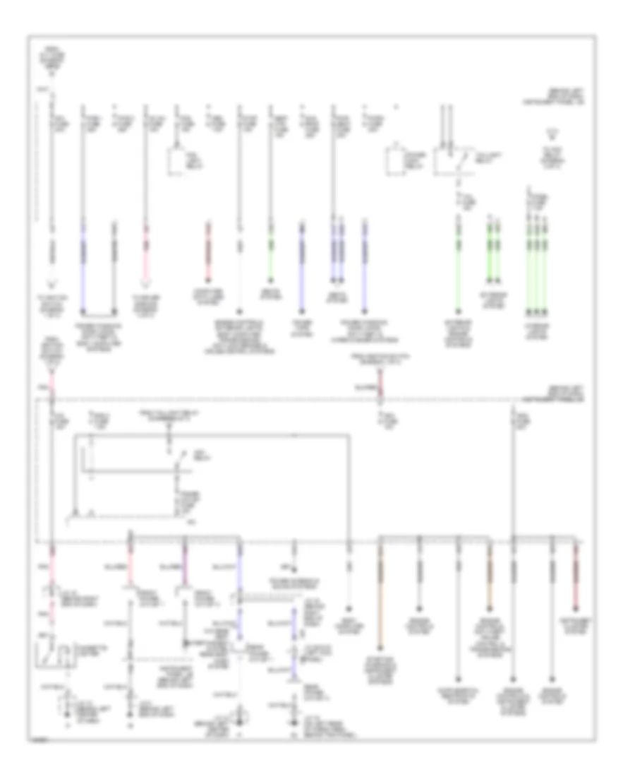
Power Distribution Wiring Diagram (2 of 3) for Toyota Sequoia SR5 2004
List of elements for Power Distribution Wiring Diagram (2 of 3) for Toyota Sequoia SR5 2004:
- (behind left end of dash) instrument panel j/b
- Ac inv fuse 15a
- Acc relay
- Am1 fuse 40a
- Body computer system
- Cig fuse 15a
- Cigarette lighter
- Computer data lines system
- E10
- E12
- E17
- E18
- E20
- Engine controls & instrument cluster systems
- Engine controls system
- Engine controls, anti-theft, cruise control & transmissions systems
- Engine controls, exterior lights, body computer, transmissions, anti-lock brakes & cruise control systems
- Exterior lights & engine controls systems
- Exterior lights system
- F10
- F11
- F12
- F13
- F17
- F18
- Fog fuse 15a
- Fog light relay
- From alt fuse (diagram 1 of 3)
- From ignition switch (diagram 1 of 3)
- From taillight relay (diagram 2 of 3)
- Front power outlet 1
- Front power outlet 2
- G15
- G16
- H10
- H11
- Ign1 fuse 10a
- Ign2 fuse 20a
- Instrument cluster system
- Instrument panel j/b (behind left end of dash)
- Interior lights system
- Ipo
- J/c 12 (behind left center of dash)
- J/c 16 (behind right end of dash)
- J/c 19 (on left rear of cargo area, behind trim panel)
- J/c 29 & 30 (left kick panel)
- J/c 8 (behind left end of dash)
- J29
- J30
- Obd fuse 7.5a
- Panel fuse 7.5a
- Pnk
- Power antenna & sound systems
- Power main relay
- Power outlet fuse 15a
- Power tops system
- Power windows, door locks, anti-theft & body computer systems
- Power windows, door locks, anti-theft & wiper/washer systems
- Pwr 1 fuse 25a
- Pwr 2 fuse 25a
- Pwr 5 fuse 30a
- Pwr seat fuse 30a
- Rad 2 fuse 7.5a
- Rear power outlet 1
- Rear power outlet 2
- Seat htr fuse 15a
- Seats system
- Starting/ charging & instrument cluster systems
- Stop fuse 15a
- Sun roof fuse 25a
- Tail fuse 15a
- Taillight relay
- To acc relay (diagram 2 of 3)
- To driver side r/b (diagram 3 of 3)
- To ignition switch (diagram 1 of 3)
- W/o rear seat entertainment system, rear seat audio system
Power Distribution Wiring Diagram (3 of 3) for Toyota Sequoia SR5 2004
List of elements for Power Distribution Wiring Diagram (3 of 3) for Toyota Sequoia SR5 2004:
- (behind left end of dash) instrument panel j/b
- (on left side of engine compt) engine room r/b 3
- 4wd fuse 20a
- A j37
- Ac1
- Ac2
- Back-up light relay
- Batt charge fuse 30a
- Body computer & wiper/ washer systems
- Body computer, interior lights, exterior lights, power windows, door locks, anti-theft & wiper/ washer & headlights systems
- D11
- D12
- Defogger, air conditioning, door locks & anti-theft systems
- Driver side r/b (behind left end of dash, below instrument panel j/b)
- Ecu-ig fuse 10a
- Engine controls, exterior lights, seats, instrument cluster, air conditioning, transmissions & cruise control systems
- Exterior lights system
- Exterior lights system (w/ 7 pin trailer socket)
- Exterior lights, body computer, interior lights, power windows, door locks, anti-theft, wiper/ washer, cruise control, anti-lock brakes & power antenna systems
- From fusible link block (diagram 1 of 3)
- From ignition switch (diagram 1 of 3)
- From instrument panel j/b (diagram 2 of 3)
- G10
- G11
- Gauge fuse 15a
- Gnd
- Htr fuse 10a
- Instrument cluster, power tops & mirrors systems
- Inverter relay
- Ipo
- J29
- J30
- J37 a
- J38 a
- Junction connector 19 (on left rear of cargo area, behind trim panel)
- Junction connector 29 & 30 (left kick panel)
- Junction connector 37 & 38 (left side of dash)
- Junction connector 8 (behind left end of dash)
- Main rly switch
- Pnk
- Power outlet (115v)
- Starting/ charging system
- Towing brk fuse 30a
- Towing tail fuse 30a
- Transmissions system
- Transmissions, cruise control, exterior lights, instrument cluster & anti-lock brakes systems
- Voltage inverter (left rear corner of luggage compt)
- Wip fuse 25a
- Wiper/ washer system
- Wsh fuse 25a
POWER MIRRORS
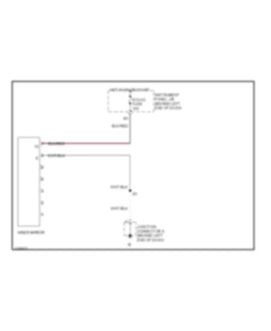
Electrochromic Mirror Wiring Diagram for Toyota Sequoia SR5 2004
List of elements for Electrochromic Mirror Wiring Diagram for Toyota Sequoia SR5 2004:
- Ecu-ig fuse 10a
- Hot in on or start
- Inner mirror
- Instrument panel j/b (behind left end of dash)
- Junction connector 8 (behind left end of dash)
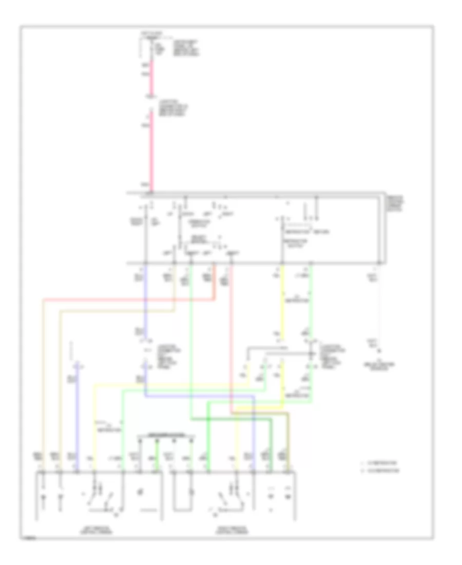
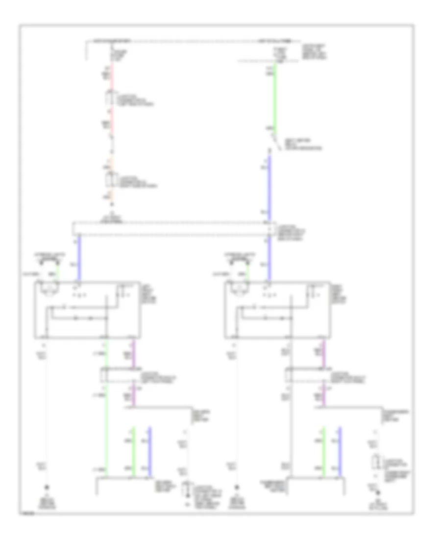
Power Mirrors Wiring Diagram for Toyota Sequoia SR5 2004
List of elements for Power Mirrors Wiring Diagram for Toyota Sequoia SR5 2004:
- A j7
- C j6
- Cig fuse 15a
- Defogger system
- Down
- Down/ right
- E20
- Hot in acc or on
- Im (below center console)
- Instrument panel j/b (behind left end of dash)
- J6 b
- J7 b
- Junction connector 16 (behind right end of dash)
- Junction connector 6 & 7 (behind left kick panel)
- Left
- Left remote control mirror
- Operation switch
- Pnk
- Remote control mirror switch
- Retraction
- Retractor switch
- Return
- Right
- Right remote control mirror
- Select switch
- Up/ left
- W/ retractor
- W/o retractor
POWER SEATS
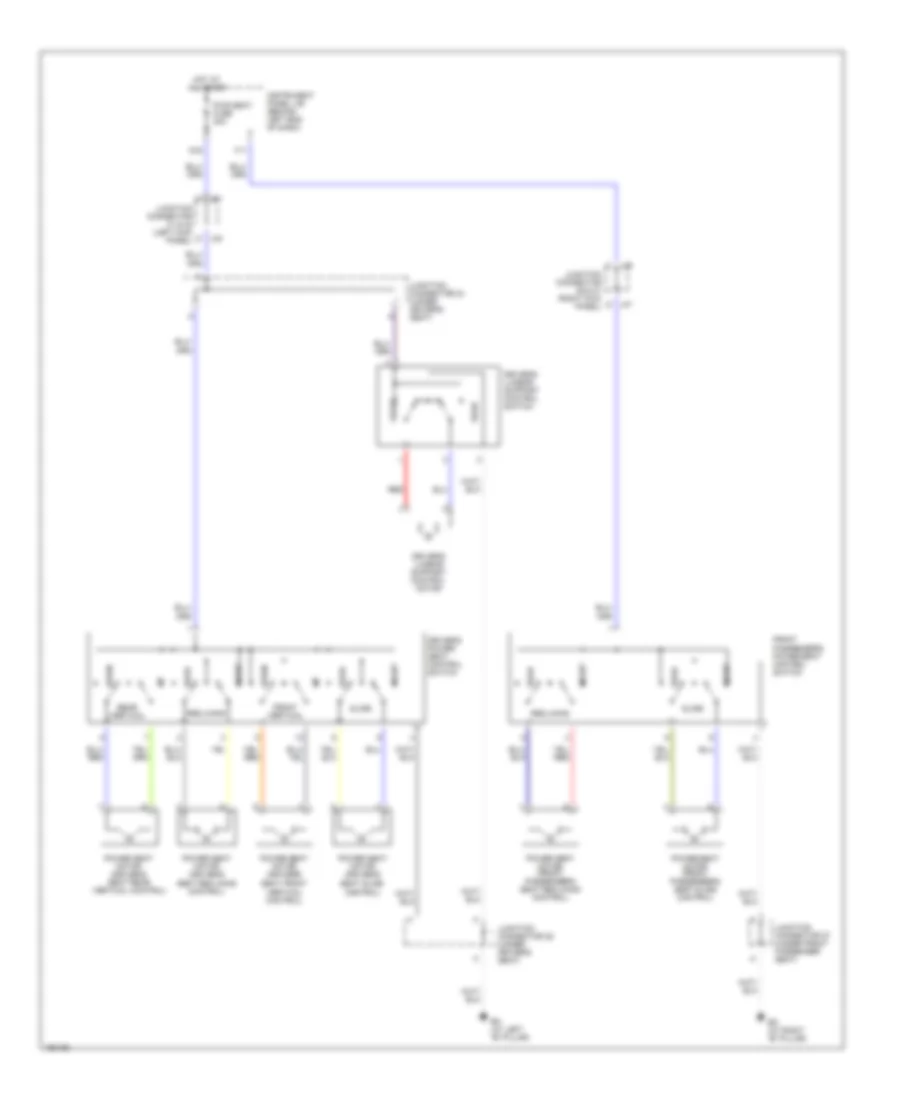
Heated Seats Wiring Diagram for Toyota Sequoia SR5 2004
List of elements for Heated Seats Wiring Diagram for Toyota Sequoia SR5 2004:
- Bk (at right "b" pillar)
- Driver's seat back heater
- Driver's seat heater
- F18
- Gauge fuse 15a
- Hot at all times
- Hot in on or start
- Ig (at right kick panel)
- Im (below center console)
- Instrument panel j/b (behind left end of dash)
- Interior lights system
- J29
- J30
- J46
- J47
- Junction connector (under front passenger seat)
- Junction connector 16 (behind right end of dash)
- Junction connector 19 (on left rear of cargo area, behind trim panel)
- Junction connector 29 & 30 (left kick panel)
- Junction connector 35 (left end of dash)
- Junction connector 43 (right side of dash)
- Junction connector 46 & 47 (right kick panel)
- Left front seat heater switch
- Passenger's seat back heater
- Passenger's seat heater
- Right front seat heater switch
- Seat heater relay (on driver side r/b)
- Seat htr fuse 15a
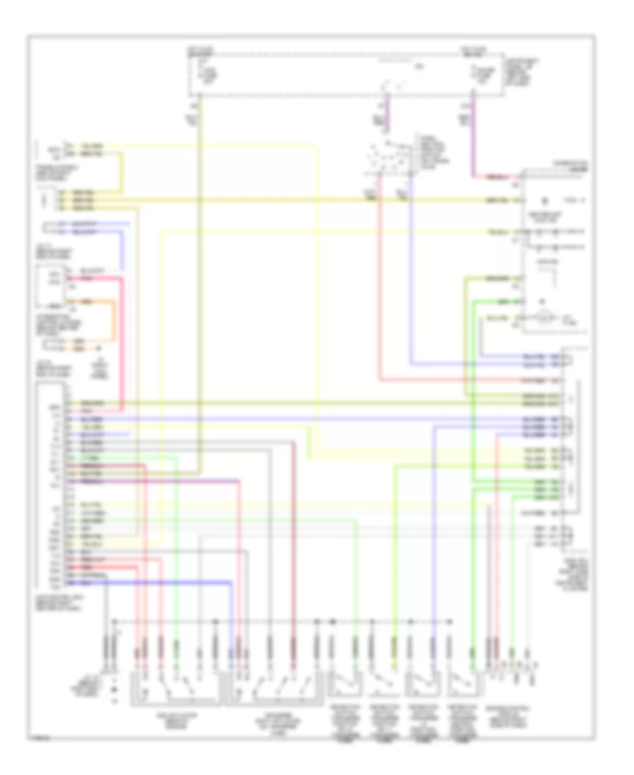
Power & Lumbar Seat Wiring Diagram for Toyota Sequoia SR5 2004
List of elements for Power & Lumbar Seat Wiring Diagram for Toyota Sequoia SR5 2004:
- Bh (at left "b" pillar)
- Bk (at right "b" pillar)
- C j31
- Down
- Driver's lumbar support control motor
- Driver's lumbar support control switch
- Driver's power seat control switch
- F11
- Front
- Front passenger's power seat control switch
- Front vertical
- G j32
- G j47
- G16
- Hot at all times
- Instrument panel j/b (behind left end of dash)
- J46 c
- Junction connector 24 (under driver's seat)
- Junction connector 25 (under driver's seat)
- Junction connector 27 (under front passenger seat)
- Junction connector 31 & 32 (left kick panel)
- Junction connector 46 & 47 (right kick panel)
- Power seat motor (driver's
- Power seat motor (driver's seat rear vertical control)
- Power seat motor (front passenger's seat reclining control)
- Power seat motor (front passenger's seat slide control)
- Pwr seat fuse 30a
- Rear
- Rear vertical
- Reclining
- Red
- Seat front vertical control)
- Seat reclining control)
- Seat slide control)
- Slide
POWER TOP/SUNROOF
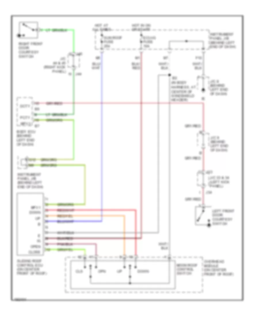
Power Top/Sunroof Wiring Diagram for Toyota Sequoia SR5 2004
List of elements for Power Top/Sunroof Wiring Diagram for Toyota Sequoia SR5 2004:
- (in body
- Body ecu (behind left end of dash)
- Close
- Cls
- Dcty
- Down
- Ecu-ig fuse 10a
- F10
- G12
- Harness, at center of windshield header)
- Hot at all times
- Hot in on or start
- Instrument panel j/b (behind left end of dash)
- J/c 33 & 34 (left kick panel)
- J/c 44 & 45 (right kick panel) n
- J/c 8 (behind left end of dash)
- J/c 9 (behind left end of dash)
- J33
- J34
- J44
- J45
- Left front door courtesy switch
- Moon roof control switch
- Mpx1
- Mpx3
- Open
- Opn
- Overhead module (on center front of roof)
- Pcty
- Right front door courtesy switch
- Sliding roof control ecu (on center front of roof)
- Sun roof fuse 25a
POWER WINDOWS
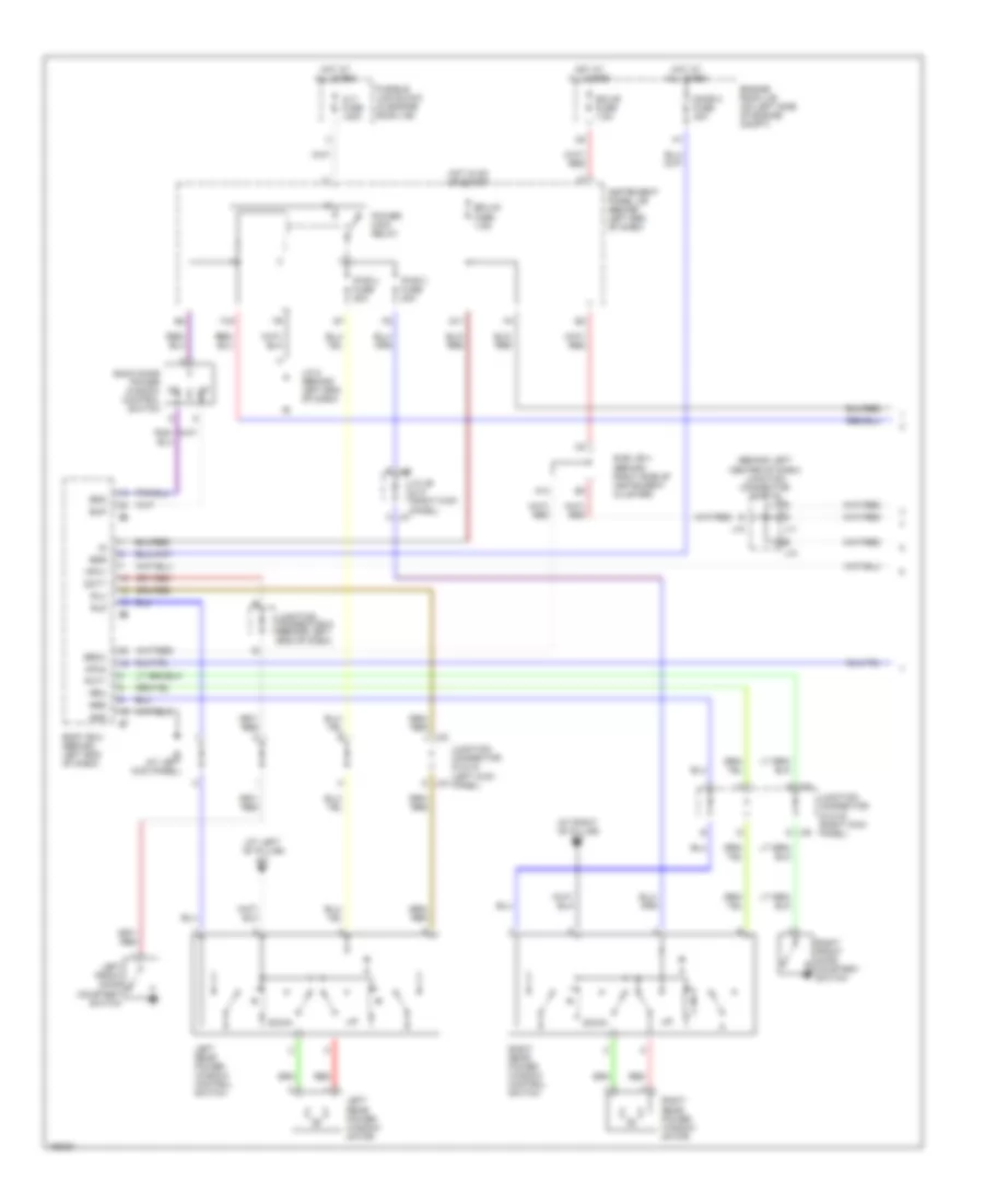
Power Windows Wiring Diagram (1 of 2) for Toyota Sequoia SR5 2004
List of elements for Power Windows Wiring Diagram (1 of 2) for Toyota Sequoia SR5 2004:
- (at left ``b" pillar) bh
- (at right ``b" pillar) bk
- (behind left center of dash) junction connector 10 & 11
- A j47
- A13
- Alt fuse 140a
- Back door power window control switch
- Bdn
- Bdr
- Becu
- Body ecu (behind left end of dash)
- Bup
- Dcty
- Door 2 fuse 30a
- Down
- E j46
- Ecu-b fuse 7.5a
- Ecu-ig fuse 7.5a
- Engine room j/b (on left side of engine compt)
- F16
- Fusible link block (in engine room j/b)
- G11
- Gnd
- Hot at all times
- Hot in on or start
- Ie (at left kick panel)
- Instrument panel j/b (behind left end of dash)
- J/c 46 & 47 (right kick panel)
- J/c 8 (behind left end of dash)
- J10
- J11
- J33 j
- J34 d
- J44 n
- J45 g
- Junction connector 33 & 34 (left kick panel)
- Junction connector 44 & 45 (right kick panel)
- Junction connector 9 (behind left end of dash)
- Left front door courtesy switch
- Left rear power window control switch
- Left rear power window motor
- Mpx1
- Mpx2
- Pcty
- Power main relay
- Pwr 3 fuse 20a
- Pwr 4 fuse 20a
- Red
- Right front door courtesy switch
- Right rear power window control switch
- Right rear power window motor
- Rld
- Rlu
- Rrd
- Rru
- Sub j/b 4 (behind right side of instrument cluster)
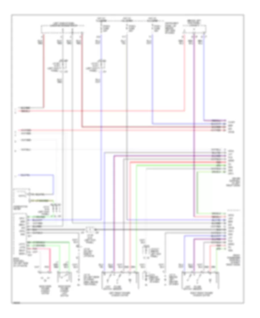
Power Windows Wiring Diagram (2 of 2) for Toyota Sequoia SR5 2004
List of elements for Power Windows Wiring Diagram (2 of 2) for Toyota Sequoia SR5 2004:
- (behind left kick panel) j/c 6 & 7
- (left side of dash) junction connector 37
- B10
- B11
- Back door ecu (on left side of liftgate)
- Back door power window limit switch
- Back door power window motor
- Bddn
- Bdr
- Bdup
- Becu
- Combination meter
- Cpub
- Data
- Ddn
- Driver door ecu (in left front door)
- F j31
- F17
- Front passenger door ecu (in right front door)
- G15
- Gnd
- Hot at all times
- Instrument panel j/b (behind left end of dash)
- J/c 12 (behind left center of dash)
- J/c 19 (on left rear of cargo area, behind trim panel)
- J/c 22 (on left side of liftgate)
- J/c 29 & 30 (left kick panel)
- J/c 31 & 32 (left kick panel)
- J/c 33 & 34 (left kick panel)
- J/c 6 & 7 (behind left kick panel)
- J/c 8 (behind left end of dash)
- J29
- J30
- J32 b
- J33
- J34
- J6 d
- J6 e
- J7 e
- J7 f
- Left front power window motor
- Limit switch
- Lmt
- Lmte
- Lmtw
- Lsw
- Mpx1
- Mpx2
- Pdn
- Pls
- Pnk
- Pulse sensor
- Pwr 1 fuse 25a
- Pwr 2 fuse 25a
- Pwr 5 fuse 30a
- Red
- Right front power window motor
- Sgnd
- Sig
- Wlsw
RADIO
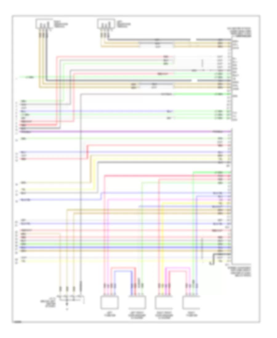
10-Speaker System Wiring Diagram, with Rear Entertainment (1 of 3) for Toyota Sequoia SR5 2004
List of elements for 10-Speaker System Wiring Diagram, with Rear Entertainment (1 of 3) for Toyota Sequoia SR5 2004:
- (behind left center of dash) j/c 10 & 11
- (left kick panel) acc cut relay
- Acc+b
- Accr e8
- Amp
- Amp+b
- Ant
- Ant+b
- Au1
- Au2
- Auto antenna motor relay (behind lower center of dash)
- Beep
- Bu+b
- Cdl+
- Cdl-
- Cdr+
- Cdr-
- Eau
- Ecu-b fuse 7.5a
- Engine control module (behind right side of dash)
- Engine room j/b (on left side of engine compartment)
- Engine room r/b 3 (on left side of engine compartment)
- F12
- Gnd
- Hot at all times
- Hot in on or acc
- Instrument panel j/b (behind left end of dash)
- J/c 3 (near engine room j/b)
- J/c 37 & 38 (left side of dash)
- J/c 37 (left side of dash)
- J/c 9 (behind left end of dash)
- J10
- J11
- J37
- J38
- Mode
- Mute
- Nca
- R-l+
- R-l-
- R-r+
- R-r-
- R19
- R20
- Rad 1 fuse 25a
- Rad 2 fuse 7.5a
- Rad 3 fuse 20a
- Radio & player
- Red
- Rmut
- Rse fuse 7.5a
- S-gnd
- Seek+
- Seek-
- Sg2
- Sgnd
- Sld
- Steering switch (combination switch)
- Sub j/b 4 (behind right side of instrument cluster)
- Sw1
- Sw2
- Swg
- Txs+
- Txs-
- Vol-
10-Speaker System Wiring Diagram, with Rear Entertainment (2 of 3) for Toyota Sequoia SR5 2004
List of elements for 10-Speaker System Wiring Diagram, with Rear Entertainment (2 of 3) for Toyota Sequoia SR5 2004:
- Im (below center console)
- J/c 12 (behind left center of dash)
- J/c 48 & 49 (right kick panel)
- J48
- J49 i
- Left front door speaker & woofer
- Left rear door speaker
- Left tweeter
- Nca
- Pnk
- Red
- Right front door speaker & woofer
- Right rear door speaker
- Right tweeter
- S10
- S11
- S12
- S13
- Stereo component amplifier (front) (center of dash, below radio)
- Stereo component amplifier (rear) (below rear of center console)
10-Speaker System Wiring Diagram, with Rear Entertainment (3 of 3) for Toyota Sequoia SR5 2004
List of elements for 10-Speaker System Wiring Diagram, with Rear Entertainment (3 of 3) for Toyota Sequoia SR5 2004:
- +b1
- +b2
- Acc
- Acc1
- Acc2
- Auxl
- Auxr
- Bu+b
- Dgnd
- Dvd player
- Gnd
- Gnd1
- Gnd3
- Hp1l
- Hp1r
- Hp2l
- Hp2r
- Hpl
- Hpl+
- Hpl-
- Hpr
- Hpr+
- Hpr-
- Left headphone terminal
- Lmut
- Mute
- Nca
- Nts2
- Nts4
- Ntsc
- Ntsi
- Open
- R-l+
- R-l-
- R-r+
- R-r-
- R21
- R22
- R23
- Rear seat entertainment display
- Rear seat entertainment ecu (under rear of center console)
- Red
- Right headphone terminal
- Rmut
- Sg1
- Sg2
- Sg3
- Sg4
- Sg5
- Sg6
- Sg9
- Sgn1
- Sgn2
- Sgn3
- Sgn4
- Sgn5
- Sgnd
- Sld
- Syn2
- Sync
- Tmut
- Tvl+
- Tvl-
- Tvr+
- Tvr-
- Tx+
- Tx-
- Tx1+
- Tx1-
- Tx2+
- Tx2-
- Vg2
- Video terminal
- Vr2
10-Speaker System Wiring Diagram, without Rear Entertainment (1 of 2) for Toyota Sequoia SR5 2004
List of elements for 10-Speaker System Wiring Diagram, without Rear Entertainment (1 of 2) for Toyota Sequoia SR5 2004:
- (behind
- (left kick panel) acc cut relay
- Acc+b
- Accr
- Amp
- Amp+b
- Ant
- Ant+b
- Au1
- Au2
- Auto antenna motor relay (behind lower center of dash)
- Beep
- Bu+b
- Cluster)
- Eau
- Ecu-b fuse 7.5a
- Engine control module (behind right side of dash)
- Engine room j/b (on left side of engine compartment)
- Engine room r/b 3 (on left side of engine compartment)
- F12
- Gnd
- Hot at all times
- Hot in acc or on
- Ill+
- Ill-
- Im (below center console)
- Instrument
- Instrument panel j/b (behind left end of dash)
- Interior lights system
- J/c 10 & 11 (behind left center of dash)
- J/c 3 (near engine room j/b)
- J/c 37 & 38
- J/c 37 (left side of dash)
- J/c 48 & 49 (right kick panel)
- J/c 9 (behind left end of dash)
- J10
- J11
- J37
- J38
- J48
- J49 i
- Left rear door speaker
- Mode
- Mute
- Nca
- R-l+
- R-l-
- R-r+
- R-r-
- R19
- Rad 1 fuse 25a
- Rad 2 fuse 7.5a
- Rad 3 fuse 20a
- Radio & player
- Red
- Right
- Right rear door speaker
- Rmut
- Rse fuse 7.5a
- S-gnd
- S12
- S13
- Seek+
- Seek-
- Sg2
- Side of
- Sld
- Steering switch (combination switch)
- Stereo component amplifier (rear) (below rear of center console)
- Sub j/b 4
- Sw1
- Sw2
- Swg
- Txs+
- Txs-
- Vol-
- Vol_
10-Speaker System Wiring Diagram, without Rear Entertainment (2 of 2) for Toyota Sequoia SR5 2004
List of elements for 10-Speaker System Wiring Diagram, without Rear Entertainment (2 of 2) for Toyota Sequoia SR5 2004:
- (on center of roof, under headliner) rear seat audio controller
- Acc
- Gnd
- Hp1l
- Hp1r
- Hp2l
- Hp2r
- Hpl
- Hpr
- J/c 12 (behind left center of dash)
- Left front door speaker & woofer
- Left headphone terminal
- Left tweeter
- Nca
- Pnk
- R-l+
- R-l-
- R-r+
- R-r-
- Red
- Right front door speaker & woofer
- Right headphone terminal
- Right tweeter
- Rmut
- S10
- S11
- Sg1
- Sgn1
- Sgn2
- Sgnd
- Stereo component amplifier (front) (center of dash, below radio)
- Tx+
- Tx-
6-Speaker System Wiring Diagram for Toyota Sequoia SR5 2004
List of elements for 6-Speaker System Wiring Diagram for Toyota Sequoia SR5 2004:
- Acc cut relay (left kick panel)
- Acc+b
- Accr
- Amp
- Amp+b
- Ant
- Ant+b
- Au1
- Au2
- Auto antenna motor relay (behind lower center of dash)
- Bu+b
- Eau
- Ecu-b fuse 7.5a
- Engine control module (behind right side of dash)
- Engine room j/b (on left side of engine compt)
- F12
- Fl+
- Fl-
- Fr+
- Fr-
- Gnd
- Hot at all times
- Hot in acc or on
- Ill+
- Ill-
- Im (below center console)
- Instrument panel j/b (behind left end of dash)
- Interior lights system
- J37
- J38
- J48
- J49
- Junction connector 3 (on left side of engine compt, near engine room j/b)
- Junction connector 37 & 38 (left side of dash)
- Junction connector 48 & 49 (right kick panel)
- Left front door speaker
- Left rear door speaker
- Left tweeter
- Mode
- Pnk
- R19
- Rad 1 fuse 25a
- Rad 2 fuse 7.5a
- Radio & player
- Red
- Right front door speaker
- Right rear door speaker
- Right tweeter
- Rl+
- Rl-
- Rr+
- Rr-
- Seek+
- Seek-
- Steering switch (combination switch)
- Sub j/b 4 (behind right side of instrument cluster)
- Sw1
- Sw2
- Swg
- Vol-
STARTING/CHARGING
Charging Wiring Diagram for Toyota Sequoia SR5 2004
List of elements for Charging Wiring Diagram for Toyota Sequoia SR5 2004:
- Alt fuse 140a
- Alt-s fuse 7.5a
- Battery
- Battery ground
- Charge warning light
- Combination meter
- Ecu-ig fuse 10a
- Engine room j/b (on left side of engine compt)
- Fusible link block (in engine room j/b)
- Generator
- H11
- Hot in on or start
- Ign1 fuse 10a
- Instrument panel j/b (behind left end of dash)
- K11
- Nca
Starting Wiring Diagram for Toyota Sequoia SR5 2004
List of elements for Starting Wiring Diagram for Toyota Sequoia SR5 2004:
- Acc
- Am2 fuse 25a
- Battery
- Battery ground
- Engine control module (behind right side of dash)
- Engine room j/b (on left side of engine compartment)
- Engine room r/b 2 (on left side of engine compt)
- Fusible link block (in engine room j/b)
- Ignition switch
- Instrument panel j/b (behind left end of dash)
- J35 a
- J36
- Junction connector 28 (near engine room j/b)
- Junction connector 35 & 36 (left end of dash)
- Junction connector 41 (right side of dash)
- Junction connector 8 (behind left end of dash)
- K12
- Lock
- Nca
- Nsw
- Off
- Park/ neutral position switch (on transmission)
- Pnk
- St fuse 30a
- Sta
- Sta fuse 7.5a
- Star
- Start
- Starter
- Starter relay
- Stsw
SUPPLEMENTAL RESTRAINTS
Supplemental Restraints Wiring Diagram for Toyota Sequoia SR5 2004
List of elements for Supplemental Restraints Wiring Diagram for Toyota Sequoia SR5 2004:
- (at left "b" pillar) bh
- (at right "b" pillar) bk
- (behind lower left side of dash, right of steering column) (partial) data link connector (dlc) 3
- (front passenger air bag assembly) air bag squib
- (steering wheel pad) air bag squib
- +sl
- +sr
- -sl
- -sr
- A10
- A19
- A20
- A21
- Air bag sensor assembly (below front of center console)
- Body ecu (behind left end of dash)
- Combination meter
- D12
- E14
- Ecu-ig fuse 10a
- Engine control module (behind right side of dash)
- Esl
- Esr
- F/ps
- F10
- F15
- Gauge fuse 15a
- Gsw
- Gsw2
- Hot in on or start
- Icl+
- Icl-
- Icr+
- Icr-
- Ig1
- Ig2
- Ign1 fuse 10a
- Instrument panel j/b (behind left end of dash)
- J/c 21 (on left rear of cargo area, behind trim panel)
- J/c 25 (under driver's seat)
- J/c 26 (under front passenger seat)
- J/c 27 (under front passenger seat)
- J/c 8 (behind left end of dash)
- J10
- J11
- Junction connector j/c 10 & j/c 11 (behind left center of dash)
- Lbe+
- Left buckle switch (inside of left front seat belt buckle)
- Left curtain air bag squib
- Left front air bag sensor (on left side of radiator support)
- Left pretensioner (at base of left "b" pillar, behind trim panel)
- Left side air bag sensor (at base of left "b" pillar behind trim panel)
- Left side air bag squib
- Pl+
- Pl-
- Pr+
- Pr-
- Rbe+
- Red
- Right buckle switch (inside of right front seat belt buckle)
- Right curtain air bag squib
- Right front air bag sensor (on right side of radiator support)
- Right pretensioner (at base of right "b" pillar, behind trim panel)
- Right side air bag sensor (at base of right "b" pillar behind trim panel)
- Right side air bag squib
- Seat
- Sfl+
- Sfl-
- Sfr+
- Sfr-
- Sil
- Solid state
- Spiral cable
- Srs warning light
- Ssl+
- Ssl-
- Ssr +
- Ssr -
- Ssr+
- Ssr-
- Sub j/b 4 (behind right side of combination meter)
- Vupl
- Vupr
- W/o power seat
- W/power
TRANSMISSION
4WD Wiring Diagram for Toyota Sequoia SR5 2004
List of elements for 4WD Wiring Diagram for Toyota Sequoia SR5 2004:
- 2-4
- 4wd
- 4wd control ecu (behind right center of dash)
- 4wd fuse 20a
- 4wd ind
- A/t p ind
- A11
- A16
- Add
- Add actuator (rear of engine)
- B10
- Center diff lock ind
- Combination meter
- Cpu
- D10
- D12
- Detection switch (transfer l4 position) (transfer case)
- Detection switch (transfer neutral position) (transfer case)
- Detection switch (transfer position sw 1) (transfer case)
- Detection switch (transfer position sw 2) (transfer case)
- Dl1
- Dl2
- Dm1
- Dm2
- Engine control module (behind right side of dash)
- Exi2
- Gauge fuse 10a
- Gnd
- Hot in on or acc
- Hot in on or start
- I19
- I22
- Ig (right kick panel)
- Ind1
- Ind2
- Instrument panel j/b (behind left end of dash)
- Integration control & panel (behind center of dash)
- Ipo
- J/c 17 (behind right end of dash)
- J/c 18 (behind right end of dash)
- J/c 43 (behind right end of dash)
- Park/ neutral position switch (on trans- axle)
- Pnk
- Red
- Spd
- Sub j/b 3 (behind right side side of instrument cluster)
- Tfm
- Tl1
- Tl2
- Tl3
- Tm1
- Tm2
- Transfer shift actuator (on transfer case)
- Translate ecu (above right kick panel)
A/T Wiring Diagram for Toyota Sequoia SR5 2004
List of elements for A/T Wiring Diagram for Toyota Sequoia SR5 2004:
- (behind right side of dash) j/c 43
- (rear of left cylinder head) ec
- (rear of right cylinder head) eb
- +b2
- +bm
- 2wd
- 4wd
- A/t oil temp
- A/t oil temperature sensor (on trans- mission)
- Awd circuit
- Batt
- C/c
- C10
- Combination meter
- D10
- D12
- E01
- E02
- E03
- E17
- Efi 1 fuse 20a
- Efi relay
- Electronically controlled transmission solenoid
- Eng+
- Eng-
- Engine control module (behind right side of dash, near "a" pillar)
- Engine coolant temperature sensor (right front of engine)
- Engine room j/b (left side of engine compt)
- Engine room r/b 2 (left side of engine compt)
- Etcs fuse 10a
- F10
- Fwd control ecu (behind right center of dash)
- Gauge fuse 10a
- Ge01
- Hot at all times
- Hot in on or start
- Hot in start sta fuse 7.5a
- Ign 1 fuse 10a
- Igsw
- Instrument panel j/b (behind left end of dash)
- Ipo
- J/c 28 (left side of engine compt)
- J/c 8 (behind left end of dash)
- J/c14, j/c 15 (behind right end of dash)
- J14
- J15
- Me01
- Mrel
- Nc0-
- Nco+
- Neo
- No 1
- No 2
- No 3
- Nsw
- O/d direct clutch speed sensor (on trans- mission)
- O/d main switch
- O/d off
- Odlp
- Odms
- Oilw
- Park/neutral position switch (on transaxle)
- Pnk
- Red
- Slt
- Slt+
- Slt-
- Sp2+
- Sp2-
- Spd
- Sta
- Star
- Starting system
- Stop fuse 15a
- Stoplight switch (on bracket, above brake pedal)
- Stp
- Stsw
- Sub j/b 3 (behind right side side of instrument cluster)
- Sub j/b 4 (behind right side side of instrument cluster)
- Tfn
- Thoc
- Throttle position sensor (throttle body assembly)
- Thw
- Translate ecu (above right kick panel)
- Trc+
- Trc-
- Vehicle speed sensor (on trans- mission)
- Vta
- Vta2
WARNING SYSTEMS
Warning Systems Wiring Diagram for Toyota Sequoia SR5 2004
List of elements for Warning Systems Wiring Diagram for Toyota Sequoia SR5 2004:
- (at left "b" pillar) bh
- (at right "b" pillar) bk
- (behind center of dash) integration control & panel
- (right kick panel) j/c 44 & 45
- (under driver's seat) (w/ pwr seat) j/c 25
- (w/ pwr seat)
- (w/o pwr seat)
- A13
- Becu
- Body ecu (behind left end of dash)
- Buzzer
- Combination meter
- D12
- Dcty
- Dome fuse 10a
- Door ind
- Ecu-b fuse 7.5a
- Engine room j/b (on left side of engine compt)
- Front passenger seat belt warning light
- Gauge fuse 15a
- Gnd
- Hot at all times
- Hot in on or start
- I j34
- I19
- Ie (at left kick panel)
- Ig (at right kick panel)
- Instrument panel j/b (behind left end of dash)
- J/c 21 (on left rear of cargo area, behind trim panel)
- J/c 26 (under front passenger seat)
- J/c 27 (w/ pwr seat) (under front passenger seat)
- J/c 31 & 32 (left kick panel)
- J/c 33 & 34 (left kick panel)
- J/c 43 (right side of dash)
- J/c 8 (behind left end of dash)
- J/c 9 (behind left end of dash)
- J31 a
- J33 c
- J44
- J45
- Ksw
- Left front buckle switch (inside of left front seat belt buckle)
- Left front door courtesy switch
- Mpx2
- Pbkl
- Red
- Right front buckle switch (inside of right front seat belt buckle)
- Seat belt ind
- Seat belt warning occupant detection sensor (under front passenger seat)
- Sub j/b 4 (behind right side of instrument cluster)
- Unlock warning switch
WIPER/WASHER
Front Wiper/Washer Wiring Diagram for Toyota Sequoia SR5 2004
List of elements for Front Wiper/Washer Wiring Diagram for Toyota Sequoia SR5 2004:
- C10
- Combination meter
- Combination switch
- D11
- D12
- Front washer motor (on right front of engine compt)
- Front washer switch
- Front wiper motor (on right rear of engine compt)
- Front wiper switch
- Gauge fuse 15a
- High
- Hot in on or start
- Instrument panel j/b (behind left end of dash)
- Int
- Int time
- J/c 1 (on right front of engine compt)
- J/c 14 &15 (behind right end of dash)
- J/c 18 (behind right end of dash)
- J/c 8 (behind left end of dash)
- J14
- J15
- Low
- Off
- Solid state
- Washer level ind
- Washer level sensor (front washer motor) (on right front of engine compt)
- Wip fuse 25a
- Wsh fuse 25a
Rear Wiper/Washer Wiring Diagram for Toyota Sequoia SR5 2004
List of elements for Rear Wiper/Washer Wiring Diagram for Toyota Sequoia SR5 2004:
- (behind left end of dash) instrument panel j/b
- (inside lower center of liftgate) rear wiper motor
- (left kick panel) j/c 31 & 32
- (on right front of engine compt, behind headlight)
- A13
- B10
- B11
- Back door courtesy switch
- Back door ecu (on left side of liftgate)
- Back door key lock & unlock switch
- Back door power window control switch
- Back door power window limit switch
- Bdcy
- Bdn
- Bdr
- Becu
- Bkl
- Bkul
- Body ecu (behind left end of dash)
- Bup
- C10
- Combination meter
- Combination switch
- Ctye
- Down
- Ecu-b fuse 7.5a
- Ecu-ig fuse 10a
- Engine room j/b (on left side of engine compt)
- F j33
- G10
- G11
- G15
- Gnd
- Hot at all times
- Hot in on or start
- Instrument panel j/b (behind left end of dash)
- Int
- J/c 10 (behind left center of dash)
- J/c 19 (on left rear of cargo area, behind trim panel)
- J/c 22 (on left side of liftgate)
- J/c 29 & 30 (left kick panel)
- J/c 33 & 34 (left kick panel)
- J/c 37
- J/c 8 (behind left end of dash)
- J29 d
- J30 k
- J31
- J32
- Keye
- L j34
- Lmte
- Lmtn
- Mpx1
- Mpx2
- Off
- Power main relay
- Power windows system
- Pwr 5 fuse 30a
- Rear washer motor
- Rear wiper & washer switch
- Red
- Rwc1
- Rwls
- Rww
- Sgnd
- Sig
- Sub j/b 4 (behind right side of instrument cluster)
- Washer 1
- Washer 2
- Wig
- Wip+
- Wip-
- Wsh fuse 25a

 Čeština
 Dansk
Dansk Deutsch
 Ελληνικά
 English
 English
 Español
 Suomi
Suomi Français
 Français
 עברית
עברית Hrvatski
 Magyar
 Italiano
 日本語
日本語 한국어
한국어 Nederlands
 Polski
 Português
 Português
 Русский
 Slovenčina
 Slovenščina
 Svenska
 Türkçe
 中文 (中国)