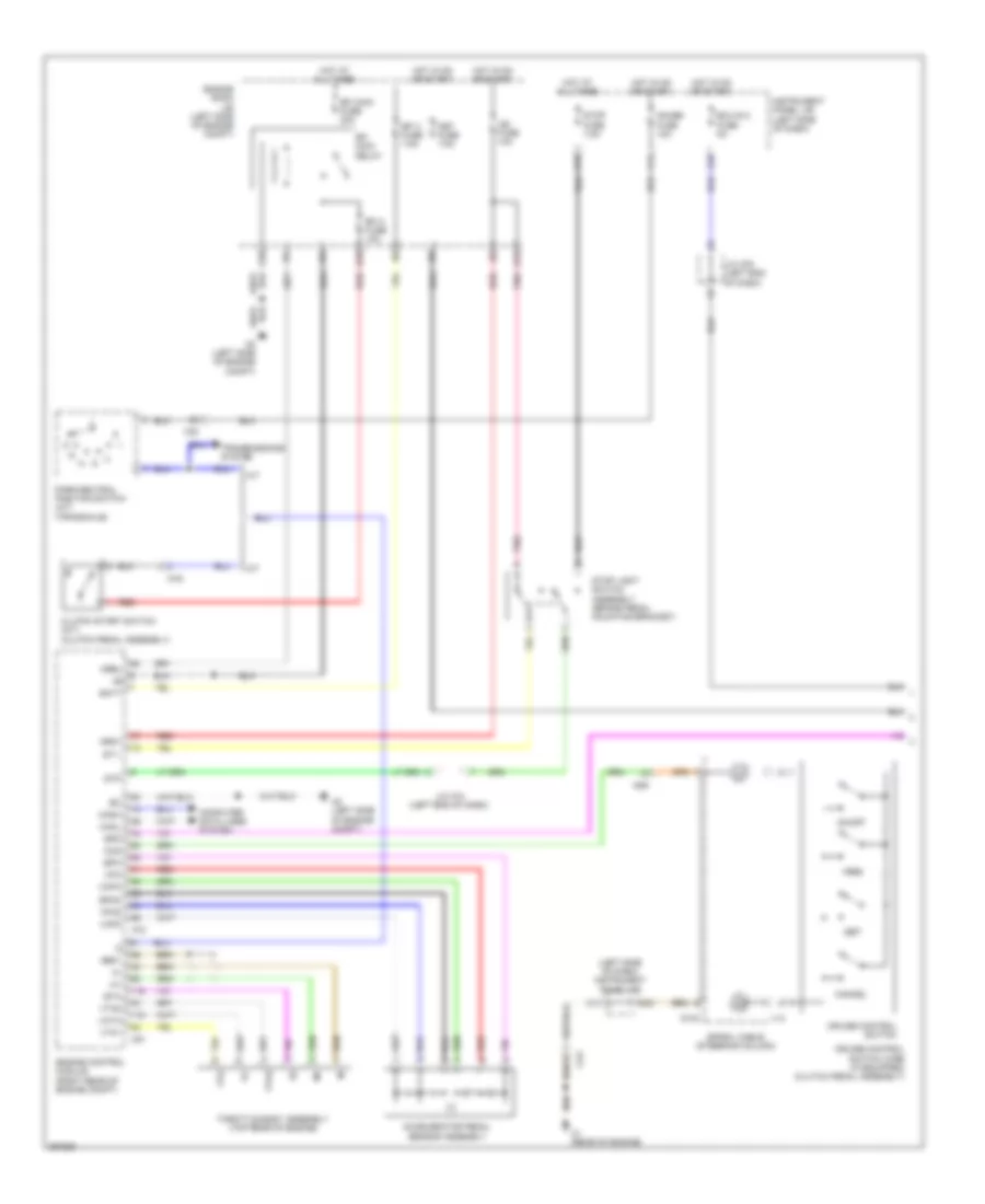
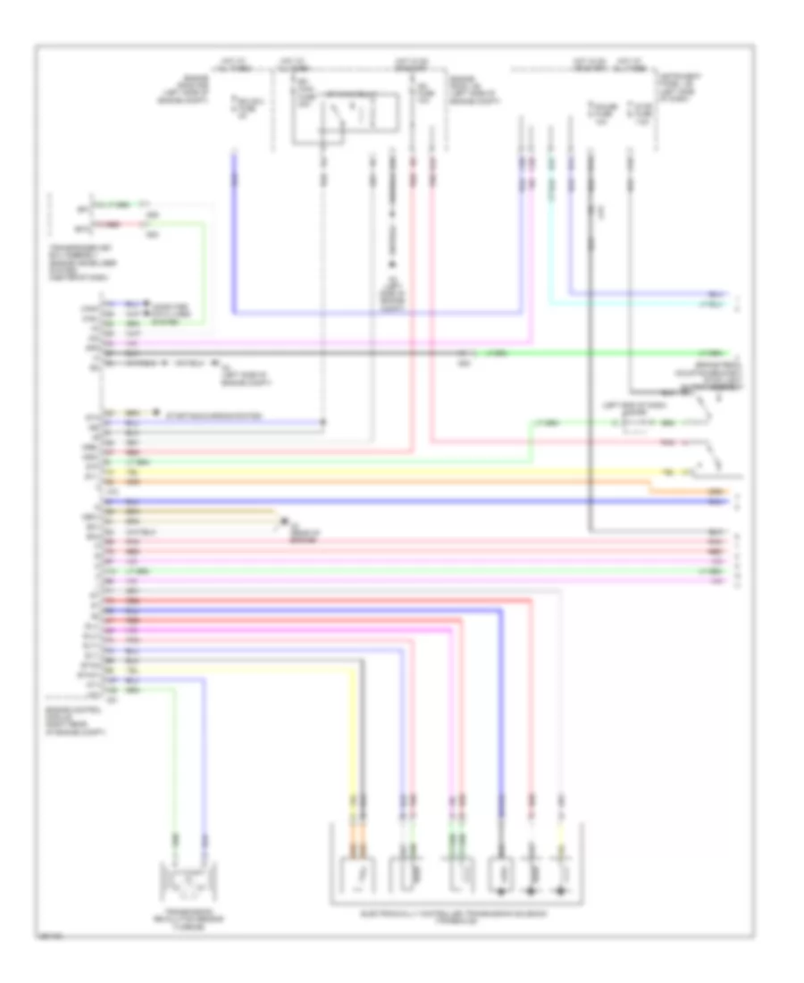
AIR CONDITIONING
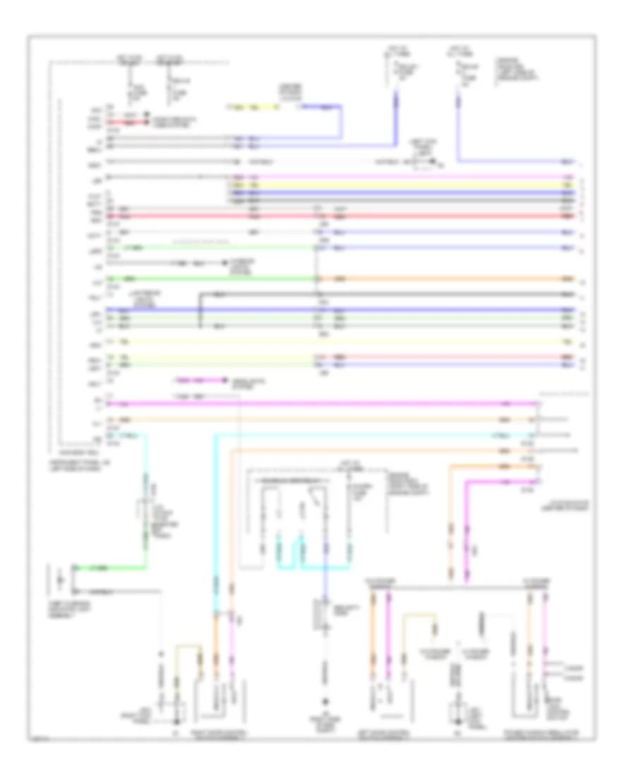
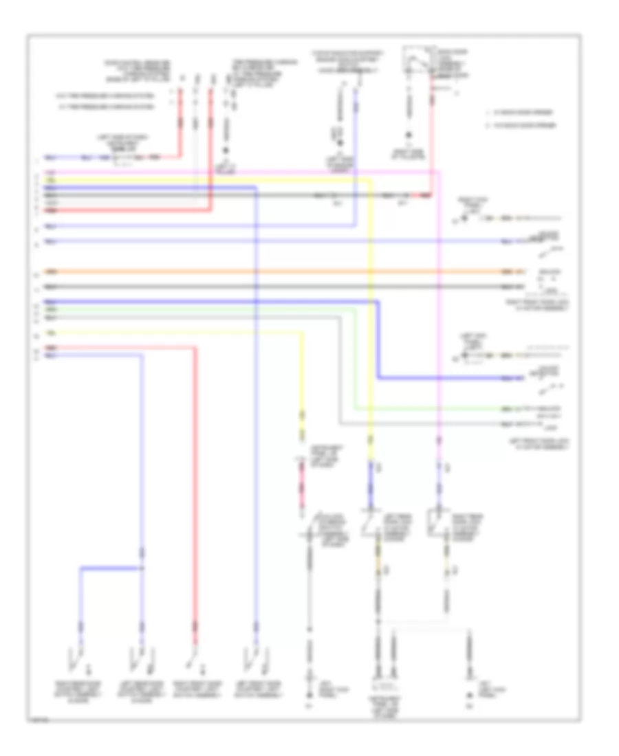
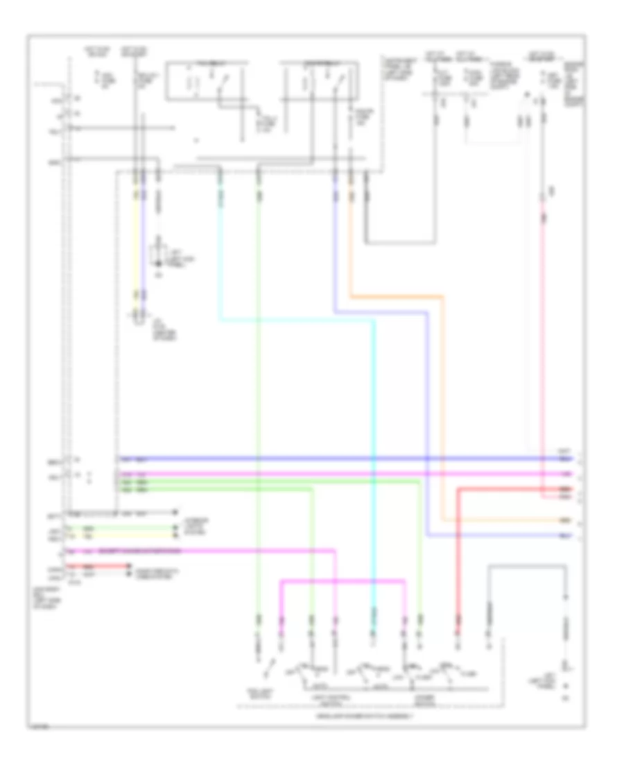
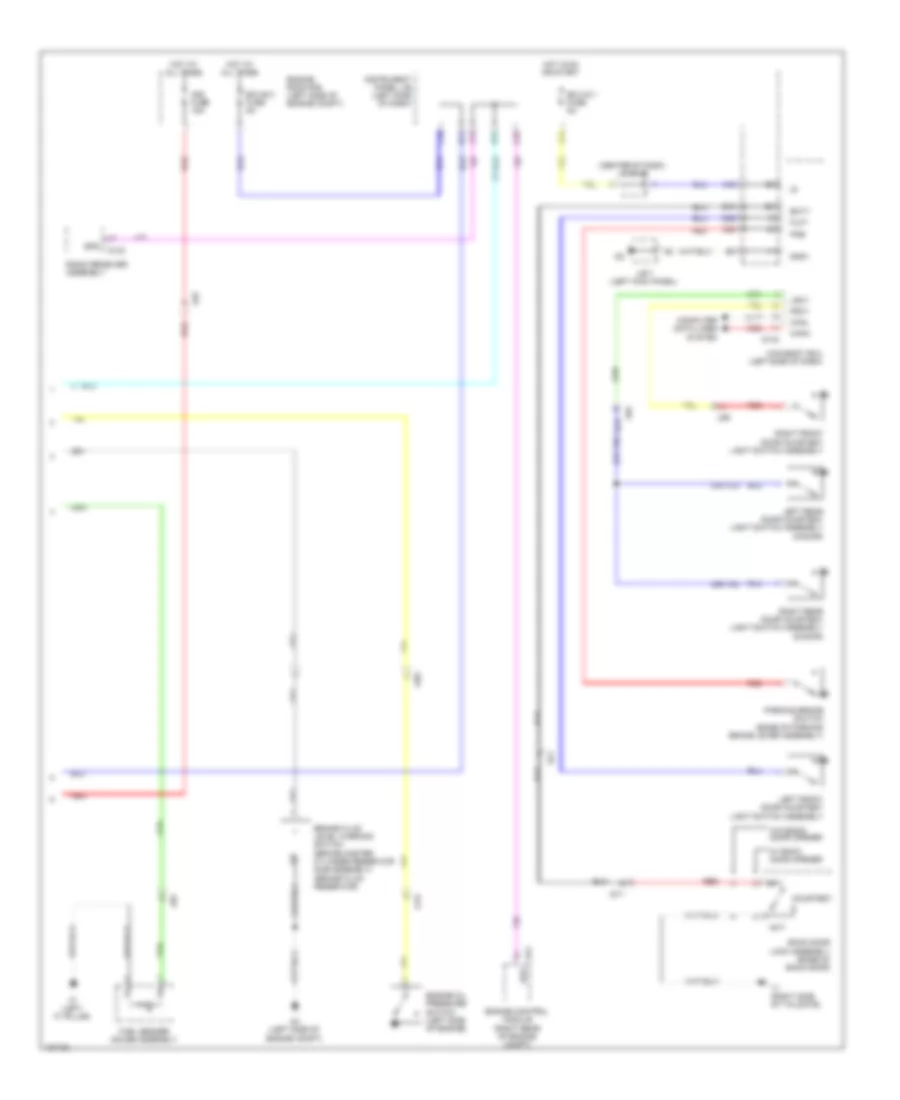
Manual A/C Wiring Diagram (1 of 2) for Toyota Yaris L 2014
 https://portal-diagnostov.com/license.html
Automotive Electricians Portal FZCO
Automotive Electricians Portal FZCO
https://portal-diagnostov.com/license.html
https://portal-diagnostov.com/license.html
Automotive Electricians Portal FZCO
Automotive Electricians Portal FZCO
List of elements for Manual A/C Wiring Diagram (1 of 2) for Toyota Yaris L 2014:
- (center of dash)
- (left kick panel)
- (left side of engine compt)
- (right side of engine compt) engine room r/b 2
- A/c
- A/c amplifier assembly
- A/c fuse 7.5a
- A/c pressure sensor (liquid tube sub-assembly) (left front of engine)
- A/c switch
- A2 (left side of engine compt)
- A22
- A5 (right side of engine compt)
- A51
- Ad7
- Ad9
- Aind
- Alt
- Blower w/ fan motor sub assembly (behind right side of dash)
- C12
- C13
- C14
- C15
- C16
- Ca3
- Computer data lines system
- Cooler thermistor 1
- Damper server motor (air inlet) (right side of dash)
- Defogger system
- Engine room j/b 2
- Engine room r/b
- Frs
- Gnd
- Gnd1
- Gnd2
- Heat
- Heater control sub- assembly
- Heater control sub-assembly 3
- Hls
- Hot at all times
- Hot in on or start
- Hrly
- Htr fuse 40a
- Htr relay
- Ig+
- Ig1
- Ill +
- Ill -
- Ill+
- Ill-
- Instrument panel j/b (left side of dash)
- Integration relay (w/ ptc heater)
- Interior lights system
- J/b 7
- J/b 8 (right kick panel)
- Led
- M m m
- Main body ecu
- Max hot switch
- Pnk
- Pre
- Ptc fuse 80a
- Ptc1
- Ptc2
- Ptc3
- Ptca
- Ptcb
- Ptcc
- Quick heater assembly
- R/b 4 (left end of dash)
- Rear window defogger switch
- Rec
- Red
- S5-3
- Sblw
- Sg-1
- Sg-2
- Sol+
- Sol-
- Timer circuit
- Tx+
- Tx-
- W/ ptc heater
- W/ pulley compressor assembly
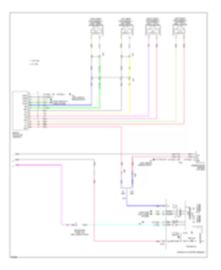
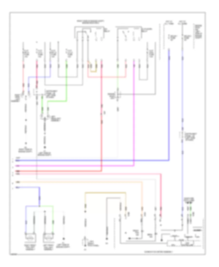
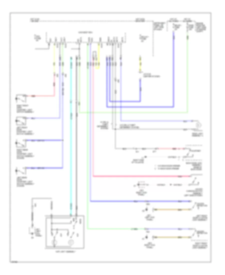
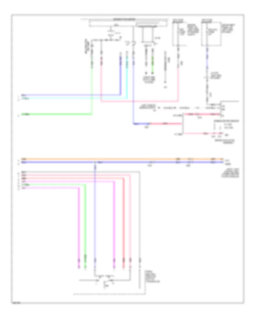
Manual A/C Wiring Diagram (2 of 2) for Toyota Yaris L 2014
List of elements for Manual A/C Wiring Diagram (2 of 2) for Toyota Yaris L 2014:
- A/c+
- A1 (left side of engine compt)
- A72
- Acid
- Air inlet control switch
- Blower assembly
- C27
- C51
- Canh
- Canl
- Computer data lines system
- Cooling fan motor (front of engine compt)
- Cooling fan resistor (left front of engine compt)
- D14
- D148
- D149
- D15
- Def-logic
- Ecu-ig 1 fuse 5a
- Engine control module (right rear of engine compt)
- Engine coolant temperature sensor (top rear of engine)
- Engine room j/b (left side of engine compt)
- Engine room r/b (left side of engine compt)
- Ethw
- F/d
- Fan relay 1
- Fan relay 2
- Fanh
- Fanl
- Free
- Frs
- Heater control sub assembly 1
- Hot at all times
- Hot in on or start
- Ill+
- Ill-
- Instrument panel j/b (left side of dash)
- Interior lights system
- J/b 8 (right kick panel)
- J/c d148 & d149 (center of dash)
- Led+
- Lock
- Rdi fan fuse 30a
- Rec
- Red
- Thw
- Tmc made
- Tmmf made
ANTI-LOCK BRAKES
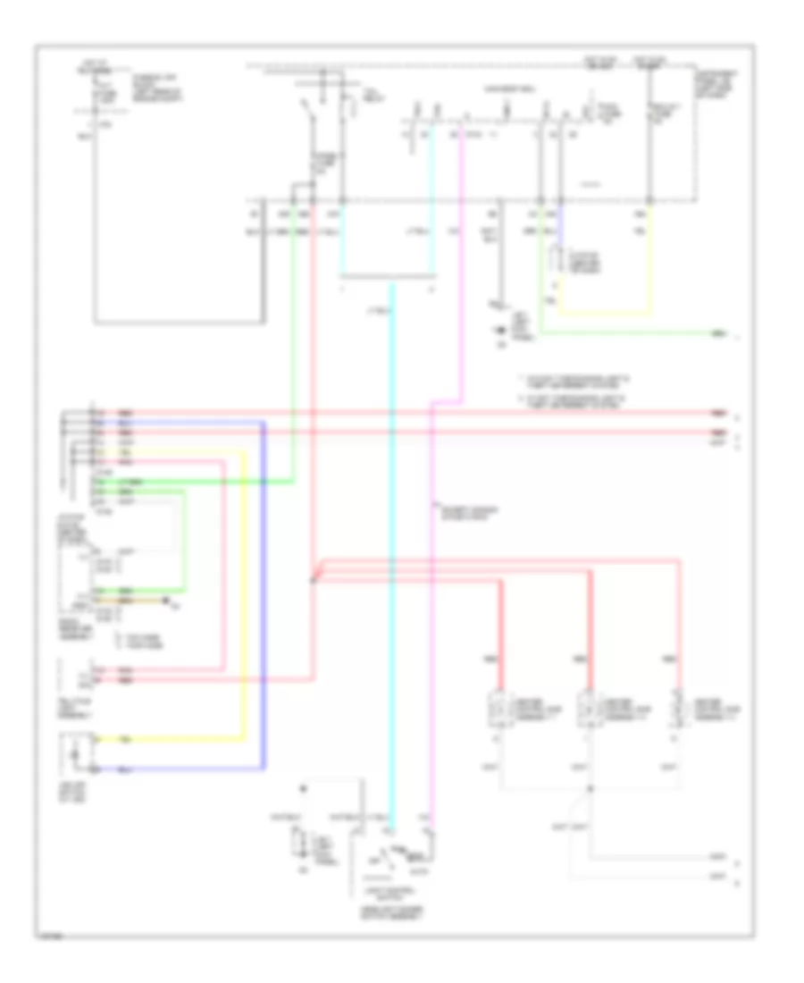
Anti-lock Brakes Wiring Diagram, with VSC (1 of 2) for Toyota Yaris L 2014
List of elements for Anti-lock Brakes Wiring Diagram, with VSC (1 of 2) for Toyota Yaris L 2014:
- (left side of engine compt) a2
- +bm
- +bs
- A2 (left side of engine compt)
- Abs 1 fuse 50a
- Abs 2 fuse 30a
- Ad9
- Aj2
- Brake actuator assembly
- C12
- C32
- Canh
- Canl
- Computer data lines system
- Cruise control system
- Csw
- Dome fuse 15a
- Ecu-ig 2 fuse 5a
- Engine room r/b (left side of engine compt)
- Fl+
- Fl-
- Fr+
- Fr-
- Gnd1
- Gnd2
- Hot at all times
- Hot in on or start
- Ig1
- Instrument panel j/b (left side of dash)
- Interior lights system
- J/b 8 (right kick panel)
- J/c a74 (left end of dash)
- J/c a76 (left end of dash)
- Left front speed sensor (left front hub assembly)
- Left rear speed sensor (left rear hub assembly)
- Pnk
- Red
- Right front speed sensor (right front hub assembly)
- Right rear speed sensor (right rear hub assembly)
- Rl+
- Rl-
- Rr+
- Rr-
- Sp1
- Stop fuse 7.5a
- Stop light switch assembly (brake pedal mounting bracket)
- Stp
- Vsc off switch
- Aj3
- Dj2
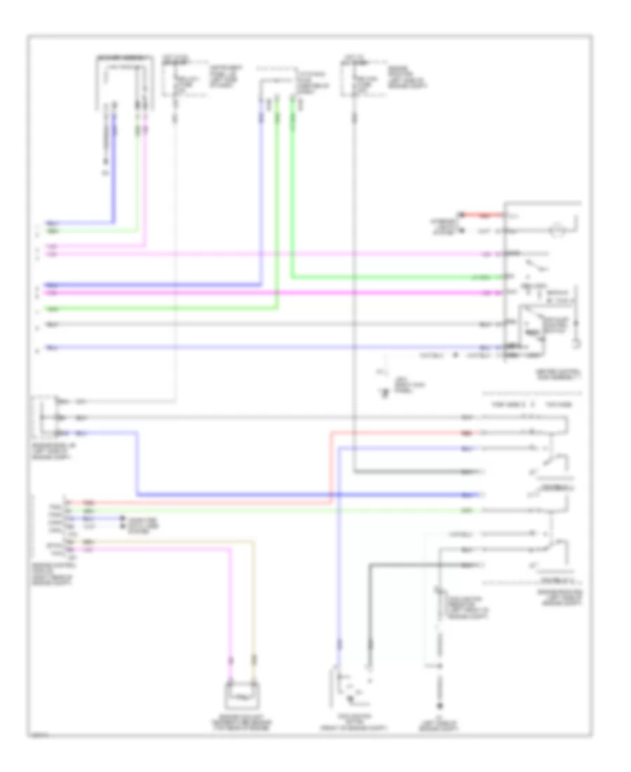
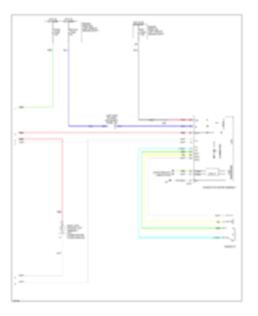
Anti-lock Brakes Wiring Diagram, with VSC (2 of 2) for Toyota Yaris L 2014
List of elements for Anti-lock Brakes Wiring Diagram, with VSC (2 of 2) for Toyota Yaris L 2014:
- (left kick panel) j/b 7
- (left side of engine compt) a2
- (right kick panel) j/b 8
- 5v +b
- 5v ic
- A28
- A54
- Abs ind
- Acc
- Acc fuse 5a
- Ad8
- Bat
- Brake fluid level warning switch (brake fluid reservoir)
- Brake ind
- Can controller
- Can i/f
- Canh
- Canl
- Combination meter assembly
- Computer data lines system
- Cpu
- D100
- D143
- D148
- D149
- Ecu-ig 1 fuse 5a
- Engine room j/b (left side of engine compt)
- Ess
- Gnd1
- Hot in on or acc
- Hot in on or start
- Ig+
- Instrument panel j/b (left side of dash)
- J/c d148 & d149 (center of dash)
- Led driver
- Main body ecu
- Met fuse 7.5a
- Parking brake switch (base of parking brake lever assembly)
- Pkb
- Pnk
- Red
- Slip ind
- Slip off ind
- Steering sensor (spiral w/ sensor cable sub-assembly)
- Trac off ind
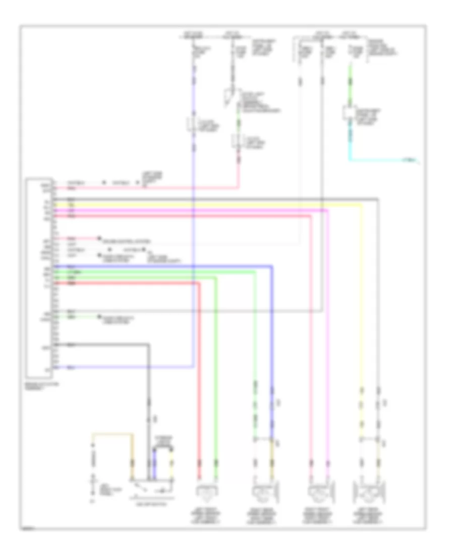
Anti-lock Brakes Wiring Diagram, without VSC for Toyota Yaris L 2014
List of elements for Anti-lock Brakes Wiring Diagram, without VSC for Toyota Yaris L 2014:
- (left side of engine compt) a2
- +bm
- +bs
- 5v +b
- 5v ic
- A2 (left side of engine compt)
- A28
- Abs 1 fuse 50a
- Abs 2 fuse 30a
- Abs ind
- Acc
- Acc fuse 5a
- Ad8
- Aj2
- Brake actuator assembly
- Brake fluid level warning switch (brake fluid reservoir)
- Brake ind
- C12
- C32
- Can controller
- Can i/f
- Canh
- Canl
- Combination meter assembly
- Computer data lines system
- Cpu
- Cruise control system
- D100
- D143
- Ecu-ig 2 fuse 5a
- Engine room j/b (left side of engine compt)
- Engine room r/b (left side of engine compt)
- Fl+
- Fl-
- Fr+
- Fr-
- Gnd1
- Gnd2
- Hot at all times
- Hot in on or acc
- Hot in on or start
- Ig+
- Ig1
- Instrument panel j/b (left side of dash)
- J/b 7 (left kick panel)
- J/c a74 (left end of dash)
- J/c a76 (left end of dash)
- Led driver
- Left front speed sensor (left front hub assembly)
- Left rear speed sensor (left rear hub assembly)
- Main body ecu
- Met fuse 7.5a
- Parking brake switch (base of parking brake lever assembly)
- Pkb
- Pnk
- Red
- Right front speed sensor (right front hub assembly)
- Right rear speed sensor (right rear hub assembly)
- Rl+
- Rl-
- Rr+
- Rr-
- Sp1
- Stop fuse 7.5a
- Stop light switch assembly (brake pedal mounting bracket)
- Stp
- Aj3
- Dj2
ANTI-THEFT
Forced Entry Wiring Diagram (1 of 2) for Toyota Yaris L 2014
List of elements for Forced Entry Wiring Diagram (1 of 2) for Toyota Yaris L 2014:
- (center of dash) j/c d148
- (left kick panel) j/b 7
- 3 door
- 5 door
- A40
- A5 (right side of eng compt)
- A54
- Acc
- Acc fuse 5a
- Ad9
- Bcty
- Becu
- C18
- C20
- C21
- Canh
- Canl
- Computer data lines system
- D143
- D144
- D148
- D149
- D24
- D25
- D35
- D36
- Door lock control switch
- Ecu-b 1 fuse 5a
- Ecu-b fuse 5a
- Ecu-ig fuse 5a
- Engine room r/b (left side of engine compt)
- Engine room r/b 2 (right side of engine compt)
- Eu-drl/s-horn relay
- Exterior lights system
- Fd3
- Flcy
- Frcy
- Gd3
- Gnd1
- Hcty
- Headlights system
- Hot at all times
- Hot in on or acc
- Hot in on or start
- Hrly
- Ile
- Ind
- Instrument panel j/b (left side of dash)
- Interior lights system
- J/b 7 (left kick panel)
- J/b 8 (right kick panel)
- J/c d148 & d149 (center d148
- J/c d148 & d149 (center of dash)
- Jd6
- Ksw
- Left door control switch assembly
- Lock
- Lrcy
- Lsfl
- Lsfr
- Lsr
- Main body ecu
- Of dash)
- Pnk
- Power window regulator master switch assembly
- Prg
- Rda
- Red
- Right door control switch assembly
- S-horn fuse 10a
- Security horn
- Theft warning indicator light assembly
- Trly
- Ul1
- Ul2
- Ul3
- Unlock
- W/ power window
- W/o power window
Forced Entry Wiring Diagram (2 of 2) for Toyota Yaris L 2014
List of elements for Forced Entry Wiring Diagram (2 of 2) for Toyota Yaris L 2014:
- (left kick panel) j/b 7
- (left side of dash) instrument panel j/b
- (right kick panel) j/b 8
- (top of radiator support) engine hood courtesy switch (hood lock assembly)
- A1 (left side of engine compt)
- A17
- A39
- Back door lock assembly (base of back door)
- C36
- D21
- D26
- Door control receiver (w/o tire pressure warning system) (base of left "d" pillar)
- Gnd
- Hj2
- Instrument panel j/b (left side of dash)
- J/b 7 (left kick panel)
- J/b 8 (right kick panel)
- J4 (left "c" pillar)
- J68
- J69
- Left front door courtesy light
- Left front door lock w/ motor assembly
- Left rear door courtesy light switch assembly (5 door)
- Left rear door lock w/ motor assembly (5 door)
- Lock
- Pnk
- Prg
- Rda
- Red
- Right front door courtesy light
- Right front door lock w/ motor assembly
- Right rear door courtesy light switch assembly (5 door)
- Right rear door lock w/ motor assembly (5 door)
- Rj1
- Sj1
- St1
- Switch assembly
- T1 (right side of tailgate)
- Tire pressure warning ecu & receiver (w/ tire pressure warning system) (left "c" pillar)
- Un-lock warning switch assembly (left side of dash)
- Unlock
- Unlock detection
- W/ back door opener
- W/ tire pressure warning system
- W/o back door opener
- W/o tire pressure warning system
Immobilizer Wiring Diagram for Toyota Yaris L 2014
List of elements for Immobilizer Wiring Diagram for Toyota Yaris L 2014:
- (center of dash) j/c d148 & d149
- (left side of dash) instrument panel j/b
- A18
- A39
- A48
- A72
- Ad8
- Ad9
- Agnd
- C31
- Code
- Computer data lines system
- Ecu-b fuse 5a
- Efii
- Efio
- Engine control module (ecm) (right rear of engine compt)
- Engine room j/b (left side of engine compt)
- Engine room r/b (left side of engine compt)
- Gnd
- Hot at all times
- Hot in on or start
- Ig2 fuse 10a
- Imi
- Imo
- Ind
- Instrument panel j/b (left side of dash)
- J/b 8 (right kick panel)
- Ksw
- Pnk
- Red
- Theft warning indicator light assembly
- Transponder key amplifier (left side of dash)
- Transponder key coil
- Transponder key ecu assembly (center of dash)
- Txct
- Unlock warning switch assembly (left side of dash)
- Vc5
- Vcs
- W/ theft deterrent system
- W/o theft deterrent system
BODY CONTROL MODULES
Body ECU Wiring Diagram (1 of 2) for Toyota Yaris L 2014
List of elements for Body ECU Wiring Diagram (1 of 2) for Toyota Yaris L 2014:
- (or red)
- A15
- A19
- A22
- A23
- A28
- A40
- A73
- Acc
- Acc fuse 5a
- Act+
- Act-
- Actd
- Altb
- Anti-lock brakes system
- Anti-theft system
- Bctl
- Bcty
- Bcyl
- Bdsu
- Becu
- C18
- C20
- C21
- C22
- C35
- Canh
- Canl
- D/l fuse 25a
- D10
- D104
- D143
- D146
- D24
- D25
- D35
- D36
- Dim
- Dome fuse 15a
- Door locks & warning systems
- Door locks system
- Drl
- Ecu-b 1 fuse 5a
- Engine room r/b (left side of engine compt)
- Exterior lights system
- Ffgo
- Ffog
- Flcy
- Frcy
- Gnd1
- Head
- Headlights system
- Hot at all times
- Hot in on or acc
- Hrly
- Ile
- Instrument panel j/b (left side of dash)
- Interior lights & exterior lights systems
- Interior lights system
- J/b 7 (left kick panel)
- J/c d146 & a73 (left end of dash)
- Koff
- Ksw
- Lrcy
- Lsfl
- Lsfr
- Lsr
- Main body ecu (left side of dash)
- Pkb
- Pnk
- Power steering ecu (left side of dash)
- Power windows system
- Prg
- Rda
- Red
- Tail
- Tlh
- Tr+
- Trly
- Trunk, tailgate, fuel doors system
- Ul1
- Ul2
- Ul3
- Warning systems
Body ECU Wiring Diagram (2 of 2) for Toyota Yaris L 2014
List of elements for Body ECU Wiring Diagram (2 of 2) for Toyota Yaris L 2014:
- A/c amplifier (center of dash)
- A54
- A72
- Air bag sensor assembly (center of dash)
- Anti-theft system
- Brake actuator assembly
- Canh
- Canl
- Combination meter assembly
- D100
- D112
- D144
- Data link connector 3 (lower left side of dash)
- Ecu-ig 1 fuse 5a
- Engine control module (right rear of engine compt)
- Hcty
- Hot in or on start
- Ind
- Instrument panel j/b (left side of dash)
- Interior lights system & anti-theft systems
- J/c d147 (center of dash)
- J/c d148 (center of dash)
- Main body ecu (left side of dash)
- Pnk
- Steering sensor (spiral w/ sensor cable sub-assembly)
- Tx+
- Tx-
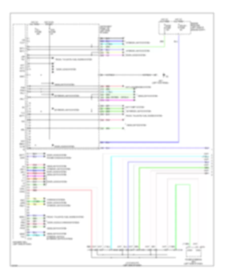
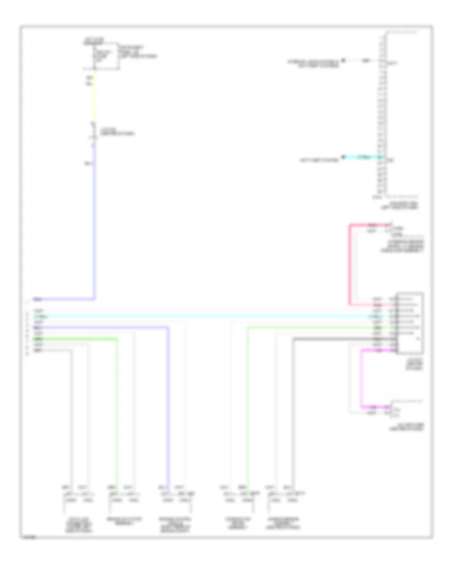
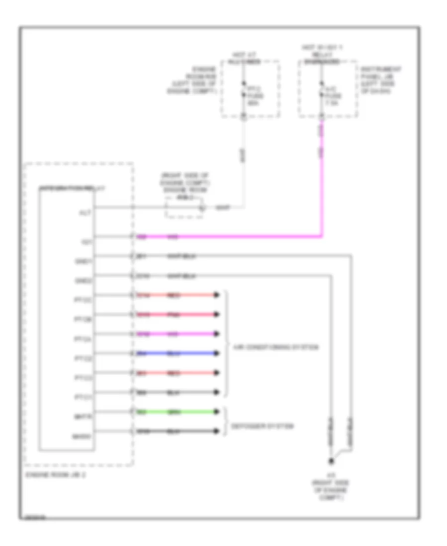
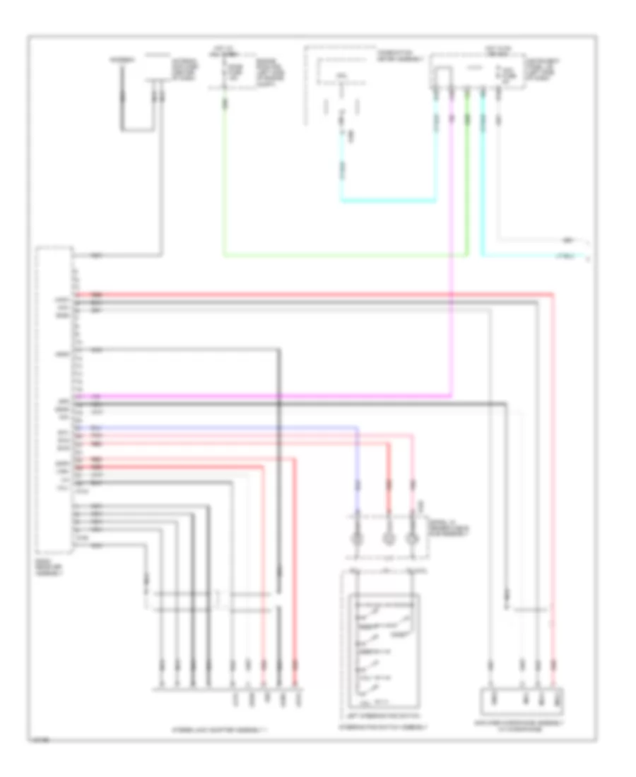
Integration Control and Panel Wiring Diagram for Toyota Yaris L 2014
List of elements for Integration Control and Panel Wiring Diagram for Toyota Yaris L 2014:
- (right side of engine compt) engine room r/b 2
- A/c fuse 7.5a
- A5 (right side of engine compt)
- Air conditioning system
- Alt
- C10
- C12
- C13
- C14
- C15
- C16
- Defogger system
- Engine room j/b 2
- Engine room r/b (left side of engine compt)
- Gnd1
- Gnd2
- Hot at all times
- Hot w/ ig1 1 relay energized
- Ig1
- Instrument panel j/b (left side of dash)
- Integration relay
- Mhsw
- Mhtr
- Pnk
- Ptc fuse 80a
- Ptc1
- Ptc2
- Ptc3
- Ptca
- Ptcb
- Ptcc
- Red
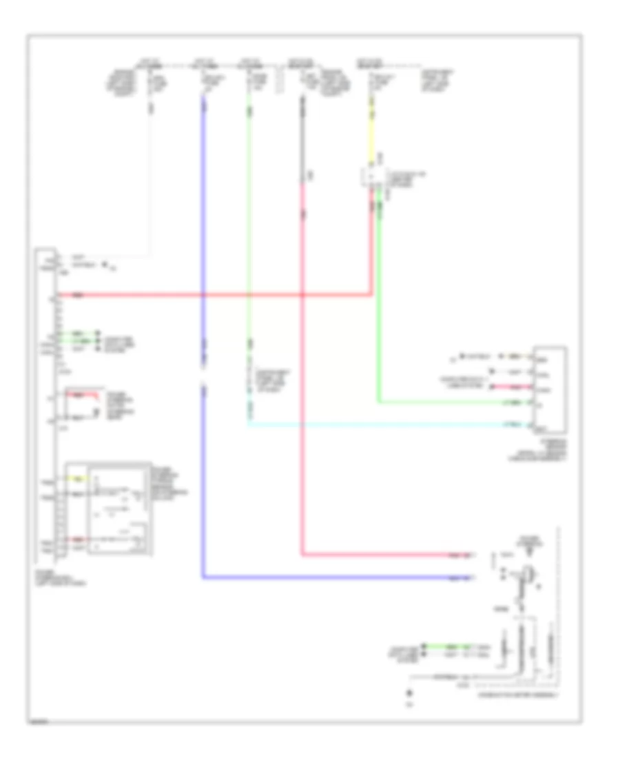
COMPUTER DATA LINES
Computer Data Lines Wiring Diagram for Toyota Yaris L 2014
List of elements for Computer Data Lines Wiring Diagram for Toyota Yaris L 2014:
- (left end of dash) j/c a73 & d146
- A/c amplifier (center of dash)
- A32
- A34
- A50
- A72
- A73
- Ad7
- Ad9
- Air bag sensor assembly
- B36
- Bat
- Brake actuator assembly
- C1 (rear of engine)
- C13
- Ca3
- Canh
- Canl
- Combination meter assembly
- D100
- D104
- D112
- D143
- D146
- D22
- Data link connector 3 (lower left side of dash)
- Engine control module (right rear of engine compt)
- Hot at all times
- Instrument panel j/b (left side of dash)
- J/b 8 (right kick panel)
- J/c d147 (center of dash)
- J4 (left "c" pillar)
- Jd6
- Jx1
- Main body ecu (left side of dash)
- Obd fuse 7.5a
- Occupant detection ecu
- Op4
- Pnk
- Power steering ecu (left side of dash)
- Red
- Right front seat inner belt assembly (right front seat)
- Sil
- Steering sensor (spiral w/ sensor cable sub-assembly) (w/ vsc)
- Tac
- Tach
- Transponder key ecu (w/ engine immobiliser system) (center of dash)
- Tx+
- Tx-
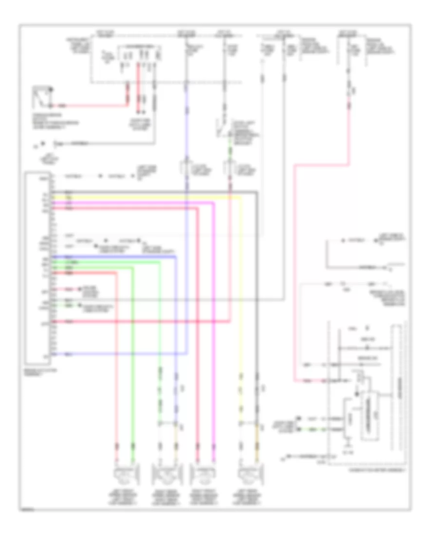
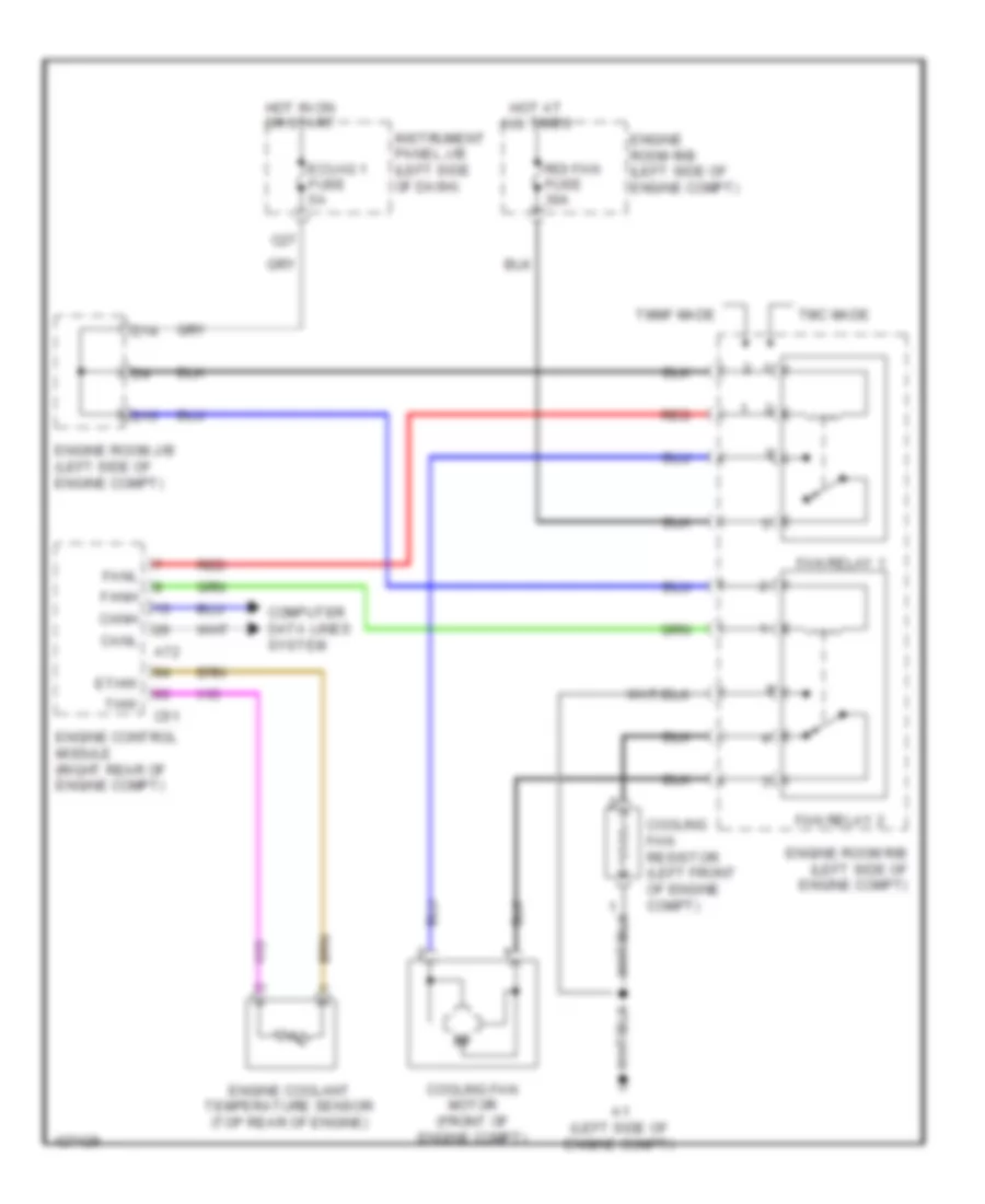
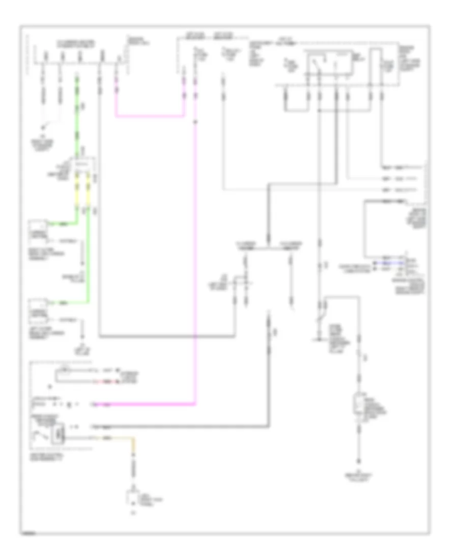
COOLING FAN
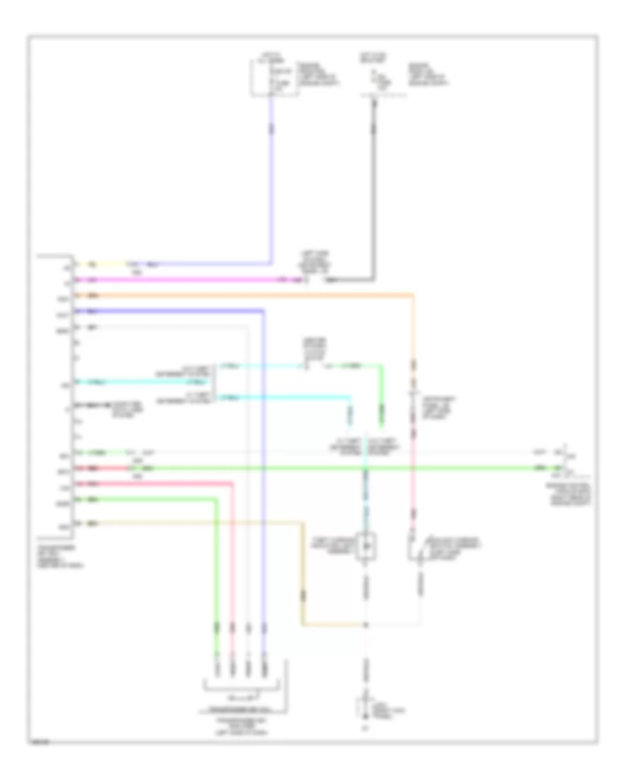
Cooling Fan Wiring Diagram for Toyota Yaris L 2014
List of elements for Cooling Fan Wiring Diagram for Toyota Yaris L 2014:
- A1 (left side of engine compt)
- A72
- C27
- C51
- Canh
- Canl
- Computer data lines system
- Cooling fan motor (front of engine compt)
- Cooling fan resistor (left front of engine compt)
- D14
- D15
- Ecu-ig 1 fuse 5a
- Engine control module (right rear of engine compt)
- Engine coolant temperature sensor (top rear of engine)
- Engine room j/b (left side of engine compt)
- Engine room r/b (left side of engine compt)
- Ethw
- Fan relay 1
- Fan relay 2
- Fanh
- Fanl
- Hot at all times
- Hot in on or start
- Instrument panel j/b (left side of dash)
- Rdi fan fuse 30a
- Red
- Thw
- Tmc made
- Tmmf made
CRUISE CONTROL
Cruise Control Wiring Diagram (1 of 2) for Toyota Yaris L 2014
List of elements for Cruise Control Wiring Diagram (1 of 2) for Toyota Yaris L 2014:
- (left side of dash) instrument panel j/b
- +res
- -set
- A/t
- A2 (left side of engine compt)
- A33
- A72
- Accelerator pedal sensor assembly
- Ad9
- Batt
- C1 (rear of engine)
- C12
- C13
- C14
- C32
- C51
- Ca3
- Cancel
- Canh
- Canl
- Ccs
- Clutch start switch (m/t) (clutch pedal assembly)
- Computer data lines system
- Cruise control switch
- Cruise control switch wire (if equipped) (clutch pedal assembly)
- D10
- D103
- D19
- E10
- Ecu-ig 2 fuse 5a
- Efi 2 fuse 10a
- Efi 3 fuse 7.5a
- Efi main fuse 20a
- Efi main relay
- Engine control module (right rear of engine compt)
- Engine room j/b (left side of engine compt)
- Epa
- Epa2
- Eta
- Gauge fuse 10a
- Ge01
- Hot at all times
- Hot in on or start
- Ig2 fuse 10a
- Igsw
- Instrument panel j/b (left side of dash)
- J/c a74 (left end of dash)
- J/c a76 (left end of dash)
- M/t
- Met fuse 7.5a
- Mrel
- On/off
- Park/neutral position switch (a/t) (transaxle)
- Pnk
- Red
- Spd
- Spiral cable (steering column)
- St1-
- Stop fuse 7.5a
- Stop light switch assembly (brake pedal mounting bracket)
- Stp
- Throttle body assembly (top rear of engine)
- Transmissions system
- V13
- Vcp2
- Vcpa
- Vcta
- Vpa
- Vpa2
- Vta
- Vta1
- Vta2
Cruise Control Wiring Diagram (2 of 2) for Toyota Yaris L 2014
List of elements for Cruise Control Wiring Diagram (2 of 2) for Toyota Yaris L 2014:
- (left front hub assembly) left front speed sensor
- (left rear hub assembly) left rear speed sensor
- (right front hub assembly) right front speed sensor
- (right rear hub assembly) right rear speed sensor
- 5v +b
- 5v ic
- A2 (left side of engine compt)
- Ad8
- Aj2
- B15
- Brake actuator assembly
- C39
- Ca3
- Can i/f
- Canh
- Canl
- Combination meter assembly
- Computer data lines system
- Controller can
- Cpu
- Cruise ind
- D100
- Driver display
- Fl+
- Fl-
- Fr+
- Fr-
- Gnd1
- Gnd2
- I/f
- Ig+
- Instrument panel j/b (left side of dash)
- Led driver
- Pnk
- Red
- Rl+
- Rl-
- Rr+
- Rr-
- Set ind
- Sp1
- Speedometer sensor (w/o abs)
- W/ abs
- W/ vsc
- W/o abs
- W/o vsc
- Aj3
- Dj2
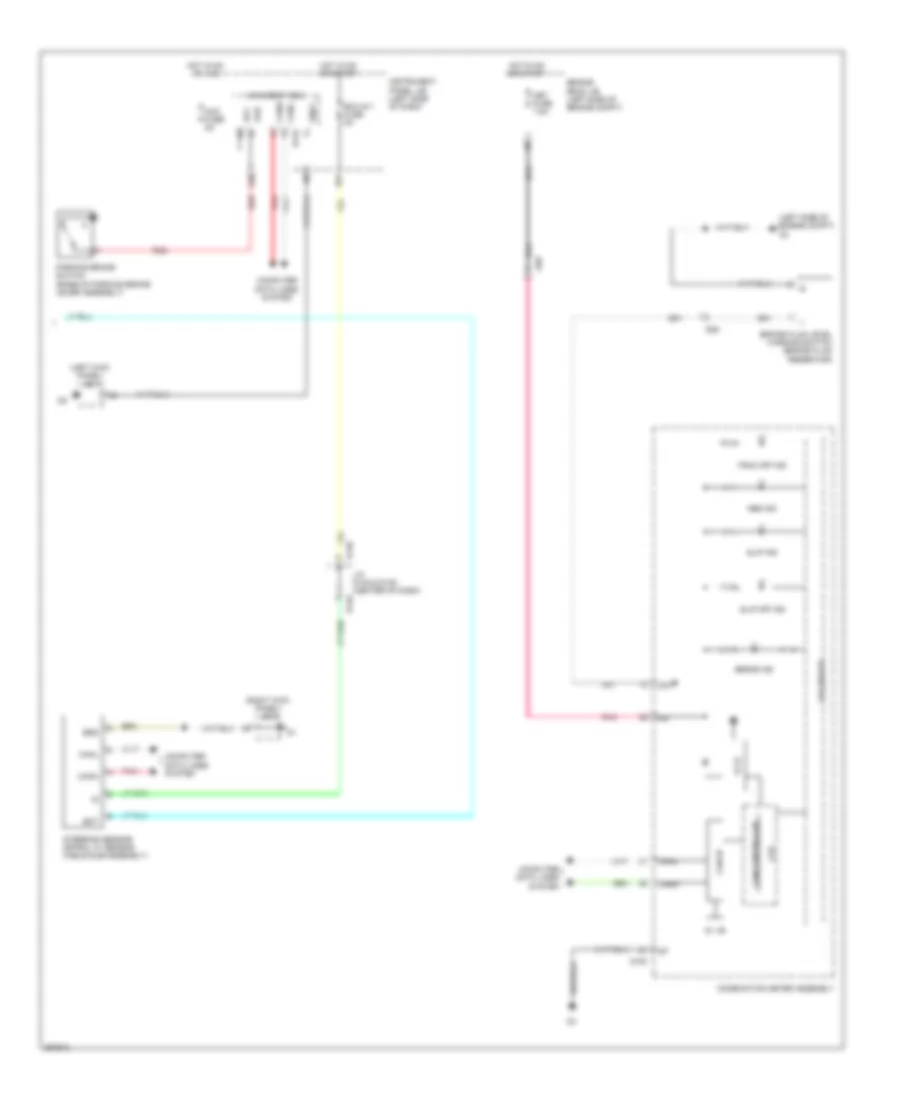
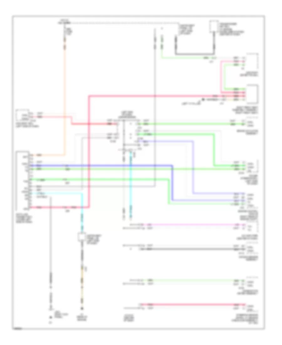
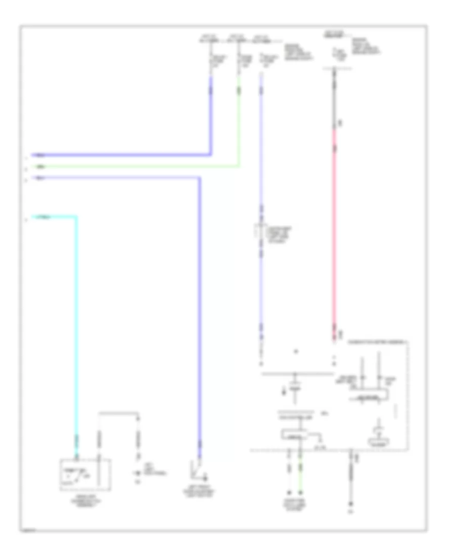
DEFOGGERS
Defoggers Wiring Diagram for Toyota Yaris L 2014
List of elements for Defoggers Wiring Diagram for Toyota Yaris L 2014:
- (left side of engine compt)
- (right side of engine compt)
- (w/ mirror heater) integration relay
- A/c fuse 7.5a
- A51
- A72
- Ad9
- Aj2
- C10
- C15
- C16
- C27
- Can h
- Can l
- Computer data lines system
- D14
- D148
- D149
- D16
- D20
- Def fuse 30a
- Def relay
- Ecu-ig 1 fuse 7.5a
- Els2
- Engine control module (right rear of engine compt)
- Engine room j/b (left side of engine compt)
- Engine room j/b 2
- Engine room r/b
- F1 (base of "c" pillar)
- Fd3
- G1 (left "b" pillar)
- Gd3
- Gnd1
- Gnd2
- Heater control sub-assembly 2
- Hot at all times
- Hot in on or start
- Id/up fuse 7.5a
- Ig1
- Instrument panel j/b (left side of dash)
- Interior lights system
- J/b 8 (right kick panel)
- J/c a76 (left end of dash)
- J/c d148 & d149 (center of dash)
- Left outer rear view mirror assembly
- Mhsw
- Mhtr
- Mirror heater
- Noise filter (rear window defogger) (left "c" pillar)
- O1 (behind right taillight)
- Rear window defogger (back door glass) o10
- Rear window defogger switch
- Red
- Right outer rear view mirror assembly
- Sj1
- Timer circuit
- W/ mirror heater
- W/o mirror heater
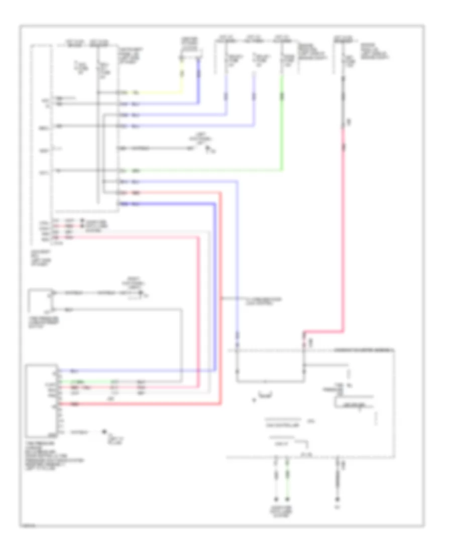
ELECTRONIC POWER STEERING
Electronic Power Steering Wiring Diagram for Toyota Yaris L 2014
List of elements for Electronic Power Steering Wiring Diagram for Toyota Yaris L 2014:
- 5v ic
- 5v+b
- A54
- A68
- Ad8
- B14
- Bat
- Buzzer
- C36
- Can controller
- Can i/f
- Canh
- Canl
- Combination meter assembly
- Computer data lines system
- Cpu
- D100
- D104
- D148
- D149
- Dome fuse 15a
- Ecu-b 2 fuse 5a
- Ecu-ig 1 fuse 5a
- Engine room j/b (left side of engine compt)
- Engine room r/b (left side of engine compt)
- Eps fuse 50a
- Ess
- Hall ic
- Hot at all times
- Hot in on or start
- I/f
- Instrument panel j/b (left side of dash)
- J/c d148 & 149 (center of dash)
- Led driver
- Met fuse 7.5a
- Pgnd
- Pig
- Pnk
- Power steering ecu (left side of dash)
- Power steering ind
- Power steering motor (steering gear)
- Power steering torque sensor (on steering column)
- Red
- Steering sensor (spiral w/ sensor cable sub-assembly)
- Trq1 c10
- Trq2
- Trqg
- Trqv
- B10
ENGINE PERFORMANCE
1.5L
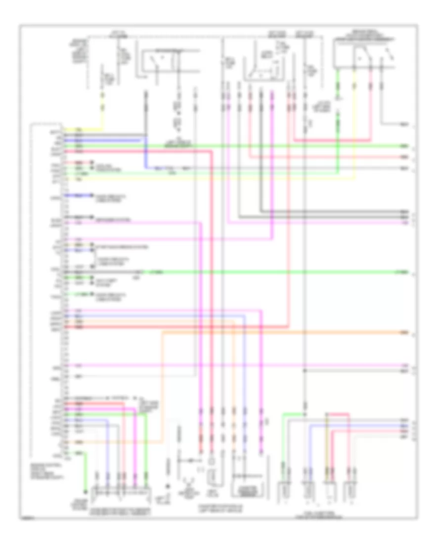
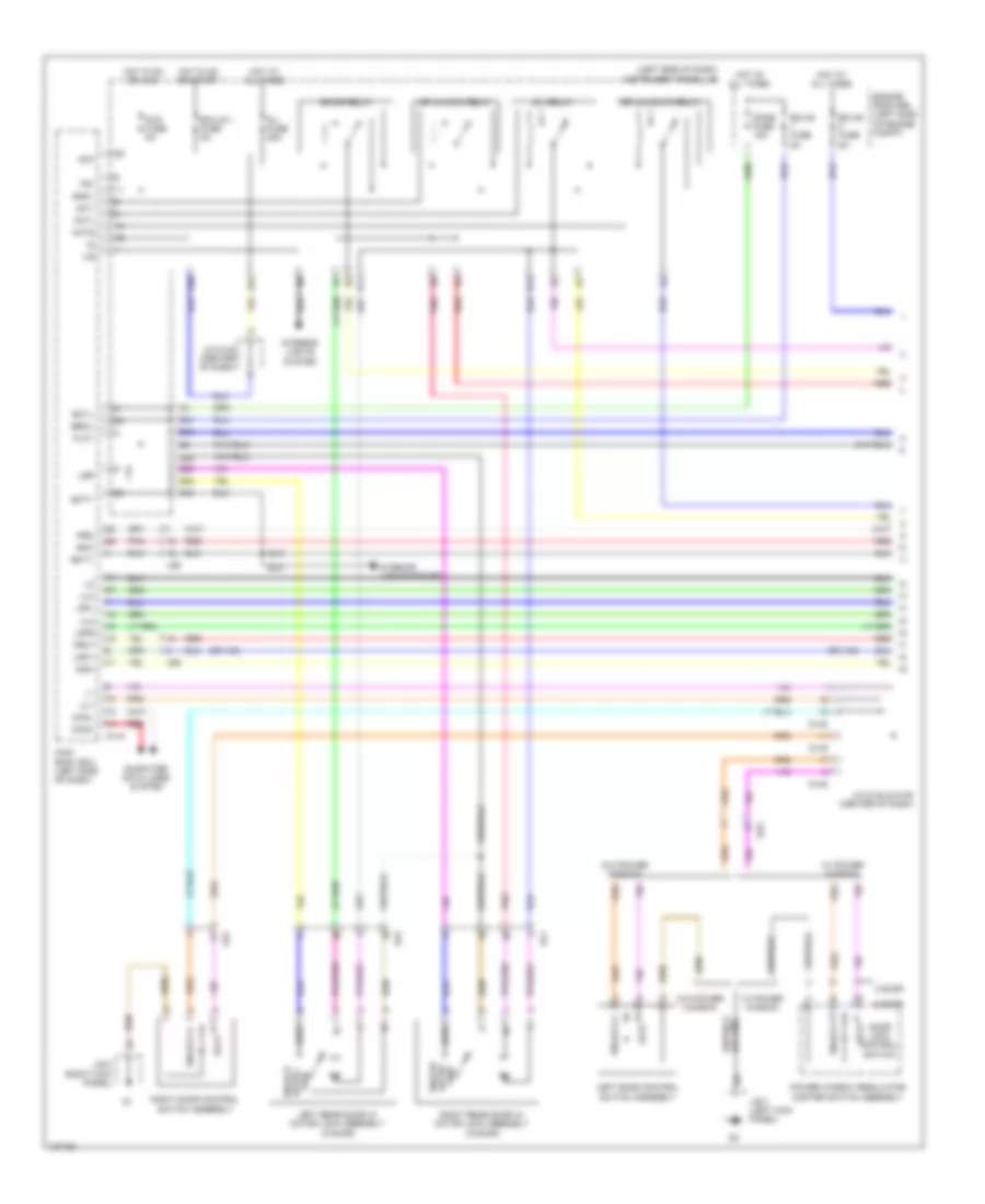
1.5L, Engine Performance Wiring Diagram (1 of 4) for Toyota Yaris L 2014
List of elements for 1.5L, Engine Performance Wiring Diagram (1 of 4) for Toyota Yaris L 2014:
- (brake pedal mounting bracket) stop light switch assembly
- +b2
- A2 (left side of engine compt)
- A72
- Accelerator position sensor (accelerator pedal assembly)
- Ad8
- Aj2
- Anti-theft system
- Batt
- C/opn relay
- Ca3
- Canh
- Canister pressure sensor
- Canister pump module (left rear of vehicle)
- Canl
- Ccs
- Computer data lines system
- Cooling fans system
- Cruise control system
- D10
- D11
- D19
- D22
- Defogger system
- E10
- E11
- Efi 2 fuse 10a
- Efi 3 fuse 7.5a
- Efi main fuse 20a
- Efi main relay
- Els1
- Els2
- Engine control module (right rear of engine compt)
- Engine room j/b (left side of engine compt)
- Epa
- Epa2
- Eppm
- Fanh
- Fanl
- Fuel injectors (top of intake manifold)
- Hot at all times
- Hot in on or start
- Ig2 fuse 10a
- Ign fuse 15a
- Igsw
- Imi
- Imo
- J/c a74 (left end of dash)
- J4 (left "c" pillar)
- Leak detection pump
- Mpmp
- Mrel
- Pnk
- Ppmp
- Red
- Spd
- St1-
- Sta
- Starting/charging system
- Stp
- Tach
- Vcp2
- Vcpa
- Vcpp
- Vent valve
- Vpa
- Vpa2
- Vpmp
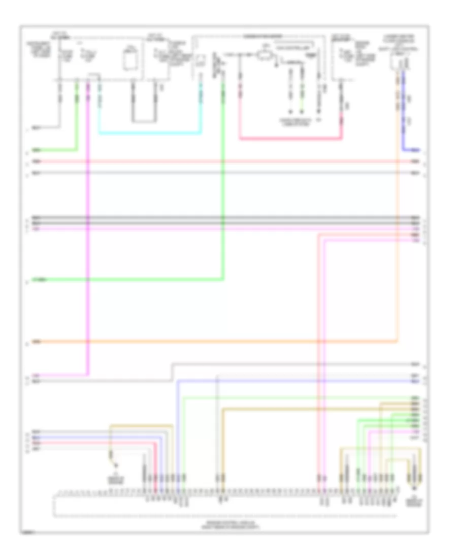
1.5L, Engine Performance Wiring Diagram (2 of 4) for Toyota Yaris L 2014
List of elements for 1.5L, Engine Performance Wiring Diagram (2 of 4) for Toyota Yaris L 2014:
- (under center floor console) (a/t) shift lock control ecu
- +bm
- 5v ic
- 5v+b
- A78
- Ad8
- Alt fuse 120a
- At3
- B15
- C1 (rear of engine)
- C12
- C2 (rear of engine)
- C39
- C51
- Ca3
- Can controller
- Can i/f
- Canh
- Canl
- Chk
- Combination meter
- Computer data lines system
- Cpu
- D100
- E01
- E02
- E04
- Engine control module (right rear of engine compt)
- Engine room j/b (left side of engine compt)
- Fusible link block (left rear of engine compt)
- Ge01
- Ha1a
- Hot at all times
- Hot in on or start
- Ht1b
- I/f
- Ig+
- Igt1
- Igt2
- Igt3
- Igt4
- Instrument panel j/b (left side of dash)
- Malfunction ind lamp
- Me01
- Met fuse 7.5a
- Nssd
- Pnk
- Red
- Slu+
- Slu-
- Stop fuse 7.5a
- Tail 2 fuse 10a
- Tail relay
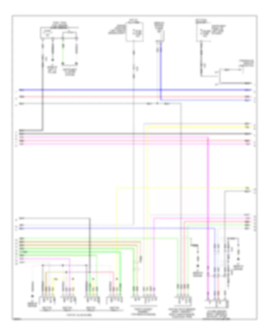
1.5L, Engine Performance Wiring Diagram (3 of 4) for Toyota Yaris L 2014
List of elements for 1.5L, Engine Performance Wiring Diagram (3 of 4) for Toyota Yaris L 2014:
- (fuel tank) fuel sender gage assembly
- (rear of engine) purge vsv
- (top of valve cover)
- (transaxle) back-up lamp switch
- A/t
- A1a+
- A1a-
- Ad10
- Air fuel ratio sensor (bank 1 sensor 1) (right side of engine, in exhaust pipe)
- Aj2
- C1 (rear of engine)
- C14
- Ca3
- Ca4
- Engine room r/b (left side of engine compt)
- Etcs fuse 10a
- Gauge fuse 10a
- Gnd
- Ha1a
- Hot at all times
- Hot in on or start
- Ht1b
- Igf
- Ignition coil 1
- Ignition coil 2
- Ignition coil 3
- Ignition coil 4
- Igt1
- Igt2
- Igt3
- Igt4
- Instrument cluster system
- Instrument panel j/b (left side of dash)
- J1 (base of left "c" pillar)
- M/t
- Nca
- Ox1b
- Oxygen sensor (bank 1 sensor 2) (exhaust, after catalytic converter)
- Pnk
- Pump
- Red
- Throttle body assembly (top rear of engine)
- Vta
- Vta2
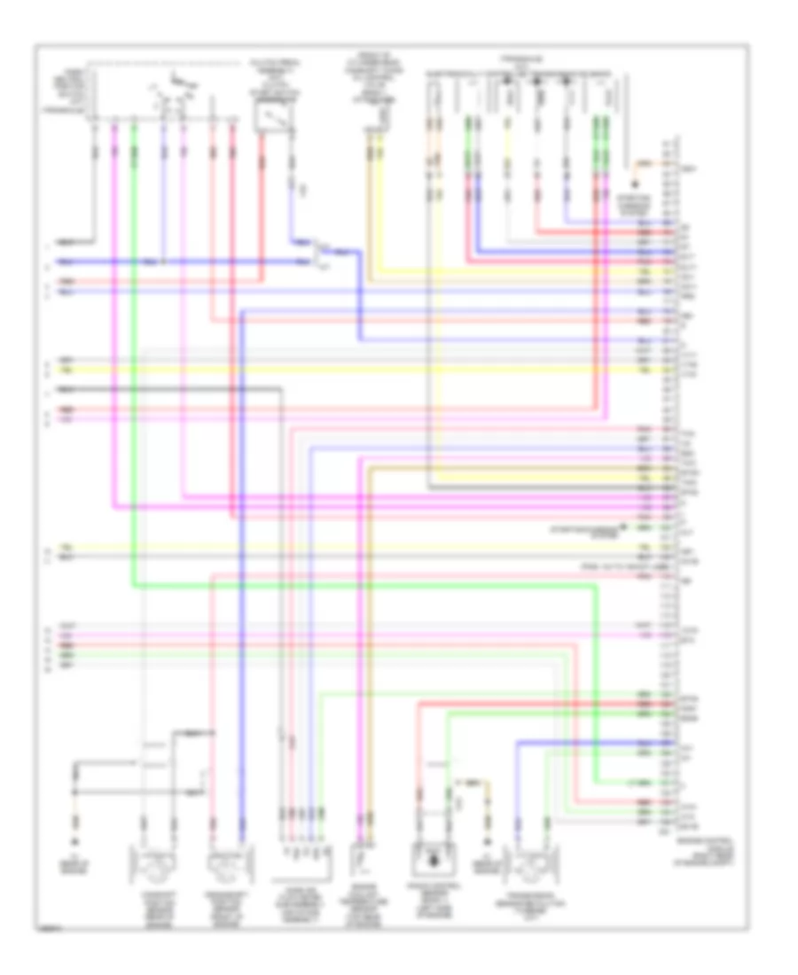
1.5L, Engine Performance Wiring Diagram (4 of 4) for Toyota Yaris L 2014
List of elements for 1.5L, Engine Performance Wiring Diagram (4 of 4) for Toyota Yaris L 2014:
- (clutch pedal assembly) (m/t) clutch start switch assembly 2
- (front of cylinder head) camshaft timing oil control valve (bank 1 intake side)
- (pins: 104 to 109 not used)
- (transaxle)
- (transaxle) (a/t)
- A/t
- A1a+
- A1a-
- Alt
- C1 (rear of engine)
- C51
- Ca3
- Camshaft position sensor (rear of engine)
- Cp2
- Crankshaft position sensor (front of engine)
- E2g
- Eknk
- Electronically controlled transmission solenoid
- Engine control module (right rear of engine compt)
- Engine coolant temperature sensor (top rear of engine)
- Eta
- Etha
- Etho
- Ethw
- Ex1b
- Igf1
- Knk1
- Knock control sensor (bank 1) (left side of engine)
- M/t
- Mass air flow meter sub-assembly (air intake assembly)
- Nca
- Ne+
- Ne-
- Nsw
- Nt+
- Nt-
- Oc1+
- Oc1-
- Ox1b
- Park/ neutral position switch (a/t)
- Pnk
- Prg
- Red
- Slt+
- Slt-
- Slu+
- Slu-
- Starting/ charging system
- Starting/charging system
- Tha
- Tho
- Tho1
- Thw
- Transmission sensor revolution (turbine) (a/t)
- Vcta
- Vta1
- Vta2
- Vv1+
EXTERIOR LIGHTS
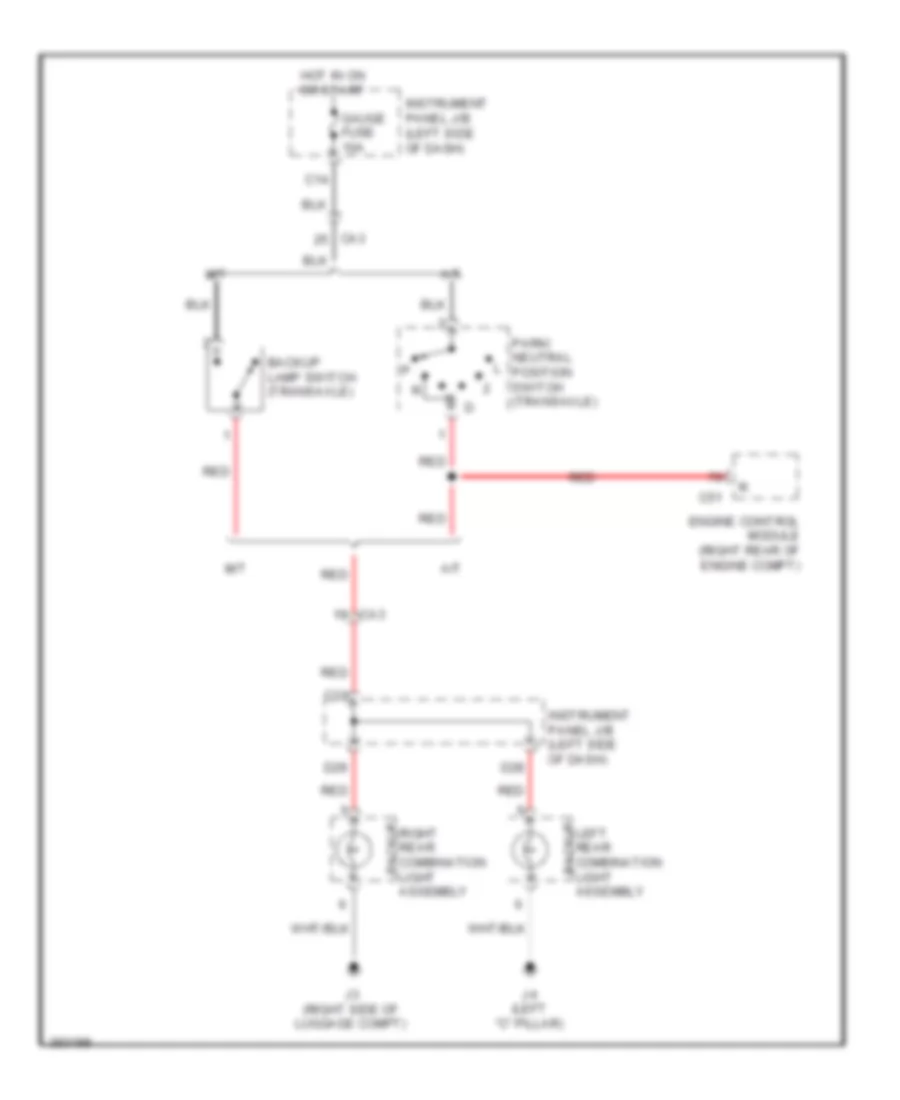
Backup Lamps Wiring Diagram for Toyota Yaris L 2014
List of elements for Backup Lamps Wiring Diagram for Toyota Yaris L 2014:
- A/t
- Assembly
- Backup lamp switch (transaxle)
- C14
- C33
- C51
- Ca3
- D28
- D29
- Engine control module (right rear of engine compt)
- Gauge fuse 10a
- Hot in on or start
- Instrument panel j/b (left side of dash)
- J3 (right side of luggage compt)
- J4 (left "c" pillar)
- Left rear combination light backup
- M/t
- Park/ neutral position switch (transaxle)
- Red
- Right rear combination light backup
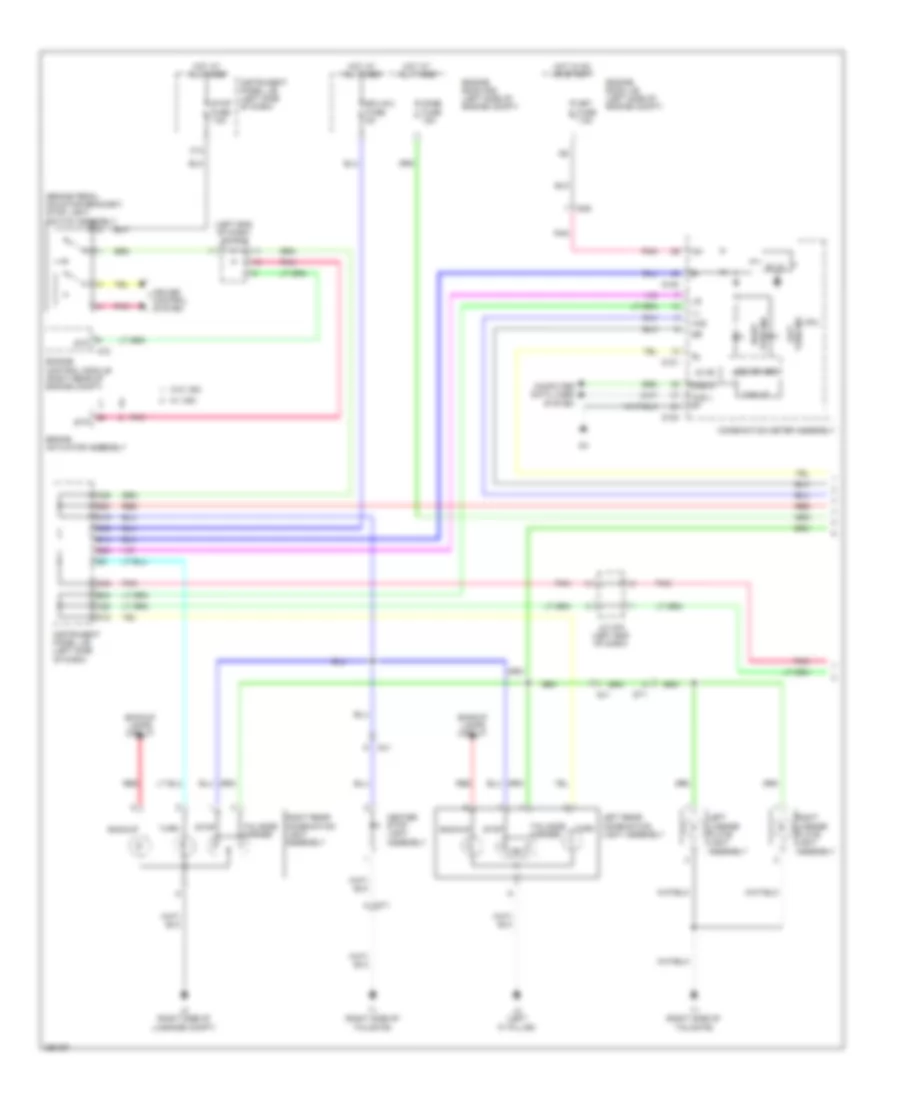
Exterior Lamps Wiring Diagram (1 of 2) for Toyota Yaris L 2014
List of elements for Exterior Lamps Wiring Diagram (1 of 2) for Toyota Yaris L 2014:
- (brake pedal mounting bracket) stop light switch assembly
- (left end of dash) j/c a74
- 5v ic
- 5v+b
- A72
- Ad8
- B14
- B24
- B25
- B30
- Backup
- Backup lamps circuit
- Brake actuator assembly
- C12
- C25
- C28
- C36
- C38
- Can h
- Can i/f
- Can l et
- Center stop light assembly
- Combination meter assembly
- Computer data lines system
- Cpu
- Cruise control system
- D100
- D101
- D18
- D19
- Dome fuse 15a
- Ecu b 2 fuse 5a
- Engine control module (right rear of engine compt)
- Engine room j/b (left side of engine compt)
- Engine room r/b (left side of engine compt)
- Haz
- Hot at all times
- Hot in on or start
- Ig+
- Instrument panel j/b (left side of dash)
- J/c a75 (left end of dash)
- J3 (right side of luggage compt)
- J4 (left "c" pillar)
- Led driver
- Left license plate light assembly
- Left rear combination light assembly
- Left turn ind
- Met fuse 7.5a
- Pnk
- Red
- Right license plate light assembly
- Right rear combination light assembly
- Right turn ind
- Sj1
- St1
- Stop
- Stop fuse 7.5a
- Stp
- T1 (right side of tailgate)
- Tail/side marker
- Turn
- W/ vsc
- W/o vsc
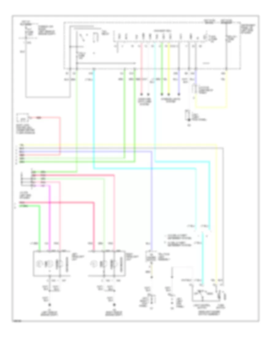
Exterior Lamps Wiring Diagram (2 of 2) for Toyota Yaris L 2014
List of elements for Exterior Lamps Wiring Diagram (2 of 2) for Toyota Yaris L 2014:
- A1 (left side of engine compt)
- A19
- A40
- A42
- A43
- A46
- A47
- A5 (right side of engine compt)
- A54
- A78
- Acc
- Acc fuse 5a
- Alt fuse 120a
- Bcyl
- Canh
- Canl
- Computer data lines system
- D10
- D143
- D36
- Deterrent system
- Ecu ig 1 fuse 5a
- Flcy
- Frcy
- Fusible link block (left rear of engine compt)
- Gnd1
- Hazard switch e
- Head
- Headlight dimmer switch assembly
- Hot at all times
- Hot in on or acc
- Hot in on or start
- Instrument panel j/b (left side of dash)
- Interior lights system
- J/b 7 (left kick panel)
- J/b 8 (right kick panel)
- J/c a76 (left end of dash)
- J/c d148 (center of dash)
- Left
- Left headlight unit
- Light control switch
- Lrcy
- Main body ecu
- Off
- Parking
- Pnk
- Red
- Right
- Right headlight unit
- Shift lock control ecu (under center floor console)
- Side marker
- Stp
- Tail
- Tail 2 fuse 10a
- Tail relay
- Telltale light assembly
- Tlh
- Trly
- Turn
- Turn switch
- W/ drl & theft deterrent system
- W/o drl & theft
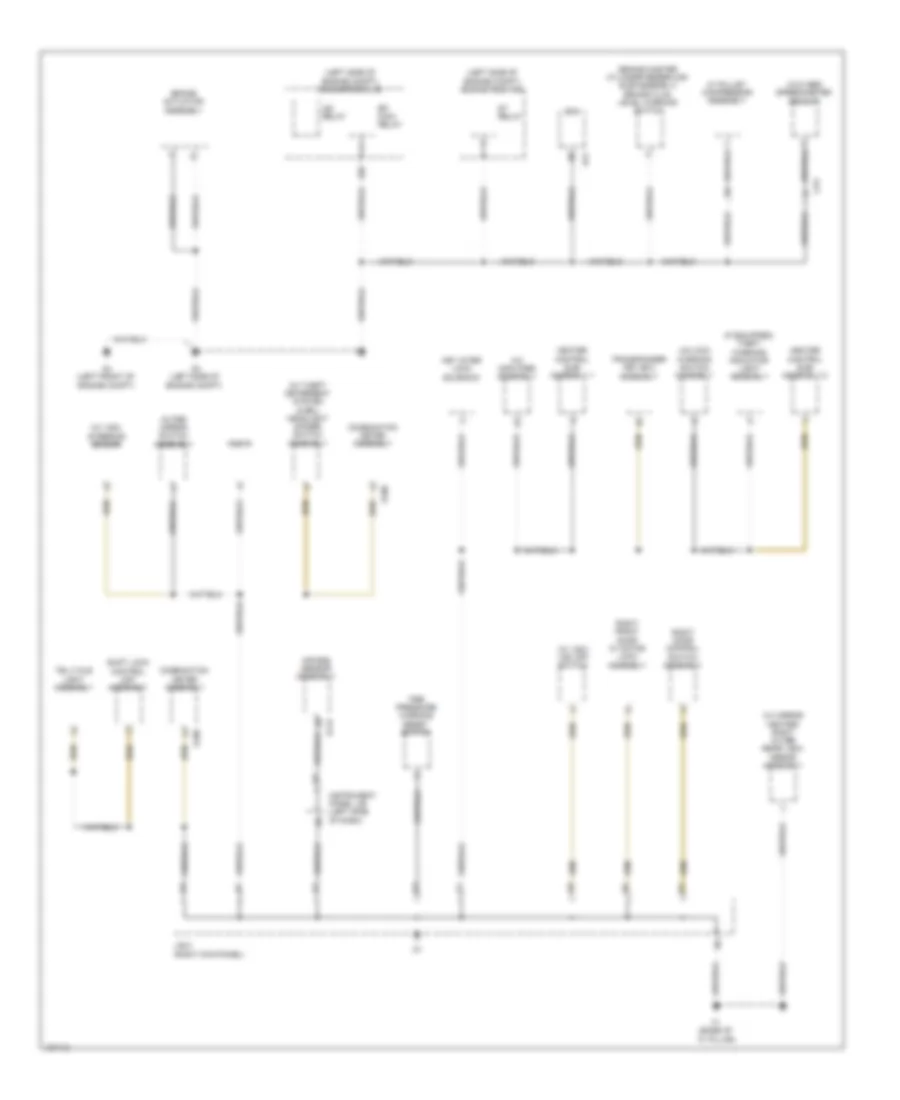
GROUND DISTRIBUTION
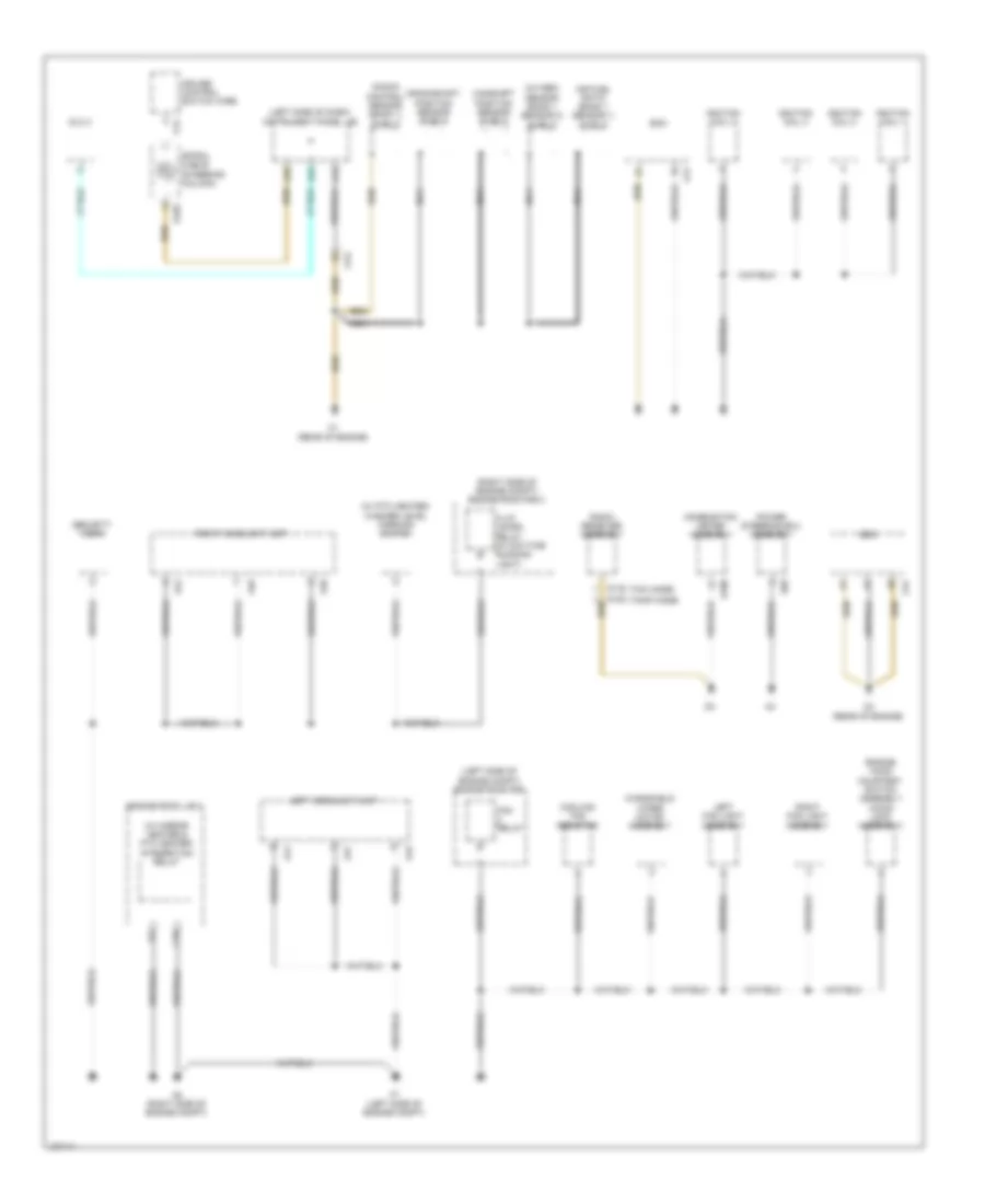
Ground Distribution Wiring Diagram (1 of 3) for Toyota Yaris L 2014
List of elements for Ground Distribution Wiring Diagram (1 of 3) for Toyota Yaris L 2014:
- (left side of dash) instrument panel j/b
- (left side of engine compt) engine room r/b
- (right side of engine compt) engine room r/b 2
- (w/ mirror heater & ptc heater) integration relay
- (w/ ptc heater) washer level warning switch
- A1 (left side of engine compt)
- A33
- A34
- A40
- A41
- A42
- A43
- A46
- A47
- A5 (right side of engine compt)
- A68
- Air fuel ratio (bank 1 sensor 1) shield
- C1 (rear of engine)
- C13
- C16
- C2 (rear of engine)
- C51
- Ca3
- Camshaft position sensor shield
- Combination meter assembly
- Cooling fan resistor
- Crankshaft position sensor shield
- Cruise control switch wire
- D100
- D103
- D132 (tmc made)
- D153 (tmmf made)
- Dlc 3
- Ecm
- Engine hood courtesy switch assembly (hood lock assembly)
- Engine room j/b 2
- Fan relay
- H-lp/ us-drl relay (w/ daytime running light)
- Ignition coil 1
- Ignition coil 2
- Ignition coil 3
- Ignition coil 4
- Knock control sensor (bank 1) shield
- Left fog light assembly
- Left headlight unit
- Nca
- Oxygen sensor (bank 1 sensor 2) shield
- Power steering ecu assembly
- Radio receiver assembly
- Right fog light assembly
- Right headlight unit
- Security horn
- Spiral cable (steering column)
- V13
- Windshield wiper motor assembly
Ground Distribution Wiring Diagram (2 of 3) for Toyota Yaris L 2014
List of elements for Ground Distribution Wiring Diagram (2 of 3) for Toyota Yaris L 2014:
- (if equipped) theft warning indicator light assembly
- (left side of engine compt) engine room j/b
- (left side of engine compt) engine room r/b
- (w/ mirror heater) right outer rear view mirror assembly
- (w/ theft deterrent system & drl) headlight dimmer switch assembly
- (w/ vsc) steering sensor
- (w/ vsc) vsc off switch
- (w/o abs) speedometer sensor
- A/c amplifier assembly
- A2 (left side of engine compt)
- A4 (left front of engine compt)
- A72
- Air bag sensor assembly
- Brake actuator assembly
- Ca3
- Combination meter assembly
- D100
- D112
- Dlc 3
- E10
- Ecm
- Efi main relay
- F1 (base of "c" pillar)
- Heater control sub- assembly 1
- Heater control sub- assembly 2
- Ig2 relay
- Instrument panel j/b (left side of dash)
- J/b 8 (right kick panel)
- Key inter lock solenoid
- Outer mirror switch assembly
- Right door control switch assembly
- Right front door w/ motor lock assembly
- Shift lock control unit assembly
- St relay
- Telltale light assembly
- Tire pressure warning reset switch
- Transponder key ecu assembly
- Un-lock warning switch assembly
- W/ pulley compressor assembly
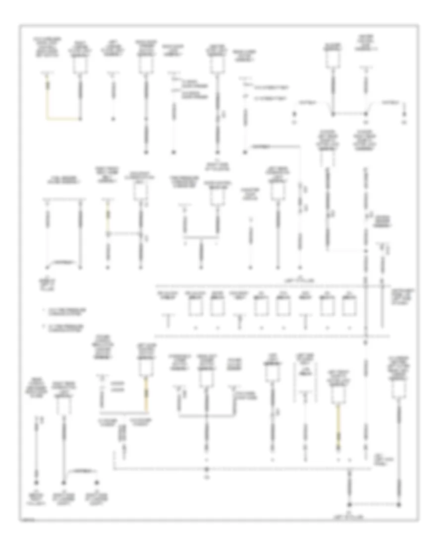
Ground Distribution Wiring Diagram (3 of 3) for Toyota Yaris L 2014
List of elements for Ground Distribution Wiring Diagram (3 of 3) for Toyota Yaris L 2014:
- (5 door) left rear door w/ motor lock assembly
- (5 door) right rear door w/ motor lock assembly
- (left end of dash) r/b 4
- (w/ mirror heater) left outer rear view mirror assembly
- (w/o wireless door lock control) back door key switch
- 3-door
- 5-door
- Acc relay
- Air bag sensor assembly
- Back door lock assembly
- Back door opener switch assembly
- Bk/dr relay
- Blower assembly
- Canister pump module
- Center stop light assembly
- D/l relay
- D107
- D112
- D26
- Door control receiver
- Dr unlock d relay
- Dr unlock relay
- Fuel sender gauge assembly
- G1 (left "b" pillar)
- Headlight dimmer switch assembly
- Heater control sub- assembly 2
- Hj2
- Htr relay
- Ig1 relay 1
- Ig1 relay 2
- Instrument panel j/b (left side of dash)
- J/b 7 (left kick panel)
- J1 (base of left "c" pillar)
- J2 (right side of luggage compt)
- J3 (right side of luggage compt)
- J4 (left "c" pillar)
- Jx1
- Kd1
- Left door control switch assembly
- Left front door w/ motor lock assembly
- Left license plate light assembly
- Left rear combination light assembly
- Main body ecu
- Map light assembly
- O1 (behind right taillight)
- O10
- Occupant classification ecu
- P/w relay
- Power outlet socket
- Power window regulator master switch assembly
- Rear window defogger (back door glass)
- Rear wiper motor assembly
- Right front seat inner belt assembly
- Right license plate light assembly
- Right rear combination light assembly
- Rj1
- Sj1
- St1
- T1 (right side of tailgate)
- Tire pressure warning ecu & receiver
- W/ back door opener
- W/ intermittent
- W/ power window
- W/ tire pressure warning system
- W/o back door opener
- W/o intermittent
- W/o power window
- W/o tire pressure warning system
- Windshield wiper switch assembly
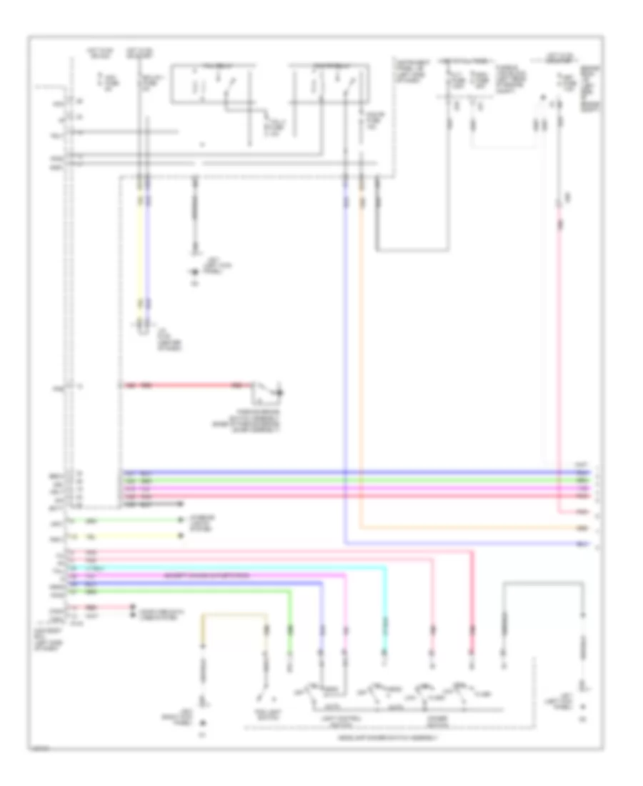
HEADLIGHTS
Headlights Wiring Diagram, with DRL (1 of 2) for Toyota Yaris L 2014
List of elements for Headlights Wiring Diagram, with DRL (1 of 2) for Toyota Yaris L 2014:
- (except canada & pueto rico)
- (left kick panel)
- A28
- A40
- A54
- A77
- A78
- Acc
- Acc fuse 5a
- Ad8
- Alt fuse 120a
- Auto
- B23
- Bcty
- Becu
- Bfg
- C18
- C21
- C22
- C35
- Canh
- Canl
- Computer data lines system
- D143
- D35
- Dim
- Dimmer switch
- Drl
- Ecu-ig 1 fuse 5a
- Engine room j/b (left side of engine compt)
- Ffgo
- Ffog
- Flash
- Fog fr fuse 15a
- Fog fr relay
- Fog light switch
- Frcy
- Fusible link block (left rear of engine compt)
- Gnd1
- Head
- Headlamp dimmer switch assembly
- High
- Hot at all times
- Hot in on or acc
- Hot in on or start
- Hrly
- Instrument panel j/b (left side of dash)
- Interior lights system
- J/b 7
- J/b 7 (left kick panel)
- J/b 8 (right kick panel)
- J/c d148 (center of dash)
- Lfg
- Light control switch
- Low
- Lrcy
- Main body ecu (left side of dash)
- Main fuse 80a
- Met fuse 7.5a
- Off
- Parking brake switch assembly (base of parking brake lever assembly)
- Pkb
- Pnk
- Red
- Tail
- Tail 2 fuse 10a
- Tail relay
- Trly
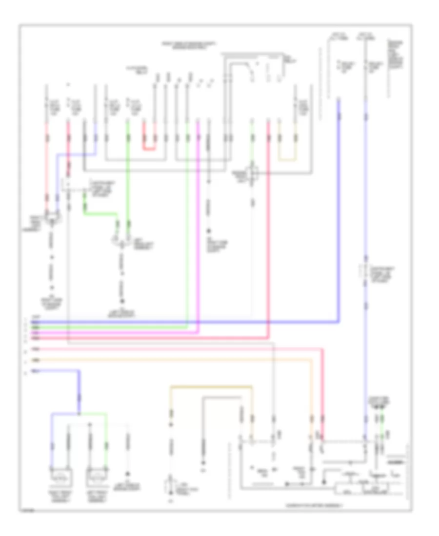
Headlights Wiring Diagram, with DRL (2 of 2) for Toyota Yaris L 2014
List of elements for Headlights Wiring Diagram, with DRL (2 of 2) for Toyota Yaris L 2014:
- (right kick panel)
- (right side of engine compt) engine room r/b 2
- 5v ic
- 5v+b
- A1 (left side of engine compt)
- A5 (right side of engine compt)
- B14
- B18
- Beam ind
- Buzzer
- C36
- Can controller
- Can i/f
- Canh
- Canl
- Combination meter assembly
- Computer data lines system
- Cpu
- D100
- D101
- Dim relay
- Drls
- Ecu-b 1 fuse 5a
- Ecu-b 2 fuse 5a
- Engine room j/b 2
- Engine room r/b (left side of engine compt)
- Fog
- Front fog ind
- H-lp lh hi fuse 10a
- H-lp lh lo fuse 10a
- H-lp main fuse 7.5a
- H-lp rh hi fuse 10a
- H-lp rh lo fuse 10a
- H-lp/us-drl relay
- Hlol
- Hlor
- Hot at all times
- I/f
- Ig+
- Instrument panel j/b (left side of dash)
- J/b 8
- Left front fog light assembly
- Left headlight assembly
- Pnk
- Red
- Right front fog light assembly
- Right head- light assembly
Headlights Wiring Diagram, without DRL (1 of 2) for Toyota Yaris L 2014
List of elements for Headlights Wiring Diagram, without DRL (1 of 2) for Toyota Yaris L 2014:
- (except canada & pueto rico)
- (left kick panel)
- A15
- A19
- A22
- A23
- A40
- A54
- A77
- A78
- Acc
- Acc fuse 5a
- Ad8
- Alt fuse 120a
- Auto
- B23
- Bcty
- Becu
- Bfg
- C18
- C21
- Canh
- Canl
- Computer data lines system
- D143
- D35
- Dimmer switch
- Ecu-ig 1 fuse 5a
- Engine room j/b (left side of engine compt)
- Flash
- Fog fr fuse 15a
- Fog fr relay
- Fog light switch
- Frcy
- Fusible link block (left rear of engine compt)
- Gnd1
- Head
- Headlamp dimmer switch assembly
- High
- Hot at all times
- Hot in on or acc
- Hot in on or start
- Hrly
- Instrument panel j/b (left side of dash)
- Interior lights system
- J/b 7
- J/b 7 (left kick panel)
- J/c d148 (center of dash)
- Lfg
- Light control switch
- Low
- Lrcy
- Main body ecu (left side of dash)
- Main fuse 80a
- Met fuse 7.5a
- Off
- Pnk
- Red
- Tail
- Tail 2 fuse 10a
- Tail relay
- Trly
Headlights Wiring Diagram, without DRL (2 of 2) for Toyota Yaris L 2014
List of elements for Headlights Wiring Diagram, without DRL (2 of 2) for Toyota Yaris L 2014:
- (right kick panel)
- (right side of engine compt) engine room r/b 2
- 5v ic
- 5v+b
- A1 (left side of engine compt)
- A5 (right side of engine compt)
- Ad7
- B14
- B18
- Beam ind
- Buzzer
- C36
- Can controller
- Can i/f
- Canh
- Canl
- Combination meter assembly
- Computer data lines system
- Cpu
- D100
- D101
- Dim relay
- Ecu-b 1 fuse 5a
- Ecu-b 2 fuse 5a
- Engine room j/b 2
- Engine room r/b (left side of engine compt)
- Fog
- Front fog ind
- H-lp lh hi fuse 10a
- H-lp lh lo fuse 10a
- H-lp main fuse 7.5a
- H-lp rh hi fuse 10a
- H-lp rh lo fuse 10a
- H-lp/us-drl relay
- Hot at all times
- I/f
- Ig+
- Instrument panel j/b (left side of dash)
- J/b 8
- Left front fog light assembly
- Left headlight assembly
- Pnk
- Red
- Right front fog light assembly
- Right head- light assembly
HORN
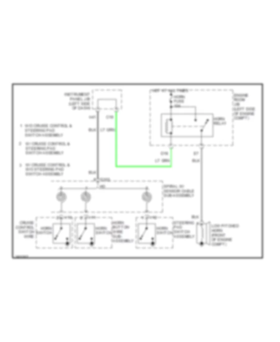
Horn Wiring Diagram for Toyota Yaris L 2014
List of elements for Horn Wiring Diagram for Toyota Yaris L 2014:
- A41
- C19
- Cruise control switch wire
- D103
- D18
- Engine room j/b (left side of engine compt)
- Horn button wire sub- assembly
- Horn fuse 10a
- Horn relay
- Horn switch
- Hot at all times
- Instrument panel j/b (left side of dash)
- Low pitched horn (front of engine compt)
- Spiral w/ sensor cable sub-assembly
- Steering pad switch assembly
- V11
- V12
- V13
- W/ cruise control & steering pad switch assembly
- W/ cruise control & w/o steering pad switch assembly
- W/o cruise control &
INSTRUMENT CLUSTER
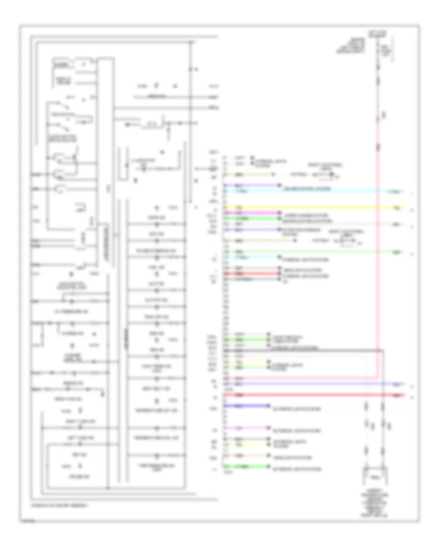
Instrument Cluster Wiring Diagram (1 of 2) for Toyota Yaris L 2014
List of elements for Instrument Cluster Wiring Diagram (1 of 2) for Toyota Yaris L 2014:
- (right kick panel) j/b 8
- 5v ic
- 5v+b
- A10
- A11
- A12
- A13
- A14
- A16
- A19
- A20
- A21
- A31
- A32
- A34
- A35
- A39
- Abs ind
- Ad8
- Ad9
- Ambient temperature sensor (thermistor assembly) (behind front grille)
- B12
- Beam ind
- Brake ind
- Buzzer
- Can controller
- Can i/f
- Canh
- Canl
- Charge ind
- Chg-
- Chk
- Clock switch drive monitor
- Combination meter assembly
- Computer data lines system
- Cpu
- Cruise control system
- Cruise ind
- D100
- D101
- Display driver
- Door ind
- Eco ind
- Engine controls system
- Engine room j/b (left side of engine compt)
- Exterior lights system
- Fog
- Front fog ind
- Fuel ind
- Haz
- Headlights system
- Hot in on or start
- I/f
- Ig+
- Ill+
- Ill-
- Ill- a40
- Illumination ind
- Interior lights system
- Led driver
- Left turn ind
- Maint reqd ind (usa)
- Malfunction indicator lamp
- Met fuse 7.5a
- Oil pressure ind
- Pnk
- Power steering ind
- Red
- Right turn ind
- Seat belt ind
- Set ind
- Slip ind
- Slip off ind
- Srs ind
- Starting/charging system
- Sw1
- Sw2
- Sw3
- Temperature cool ind
- Temperature hot ind
- Tire pressure ind (usa)
- Trac off ind
- Trip switch
- Tx1+
- Tx1-
- Washer level ind
- Wiper/washer system
- Wlvl
Instrument Cluster Wiring Diagram (2 of 2) for Toyota Yaris L 2014
List of elements for Instrument Cluster Wiring Diagram (2 of 2) for Toyota Yaris L 2014:
- (center of dash) j/c d148
- A16
- A2 (left side of engine compt)
- A28
- A40
- A54
- A72
- Act-
- Ad7
- Ad8
- B14
- B15
- Back door lock assembly (base of back door)
- Bcty
- Brake fluid level warning switch (brake master cylinder reservoir sub-assembly) (brake fluid reservoir)
- C36
- C39
- Ca3
- Canh
- Canl
- Computer data lines system
- Courtesy
- D134
- D143
- D35
- D36
- Ecu-b 2 fuse 5a
- Ecu-ig 1 fuse 5a
- Engine control module (right rear of engine compt)
- Engine oil pressure switch (left side of engine)
- Engine room r/b (left side of engine compt)
- Flcy
- Frcy
- Fuel sender gauge assembly
- Gnd1
- Haz fuse 15a
- Hot at all times
- Hot in on or start
- Instrument panel j/b (left side of dash)
- J/b 7 (left kick panel)
- J4 (left "c" pillar)
- Jd6
- Left front door courtesy light switch assembly
- Left rear door courtesy light switch assembly (5-door)
- Lrcy
- Main body ecu (left side of dash)
- Parking brake switch (base of parking brake lever assembly)
- Pkb
- Radio receiver assembly
- Red
- Right front door courtesy light switch assembly
- Right rear door courtesy light switch assembly (5-door)
- Sj1
- Spd
- St1
- T1 (right side of tailgate)
- W/ back door opener
- W/o back door opener
INTERIOR LIGHTS
Courtesy Lamps Wiring Diagram for Toyota Yaris L 2014
List of elements for Courtesy Lamps Wiring Diagram for Toyota Yaris L 2014:
- (left kick panel)
- A17
- A39
- A40
- A54
- Acc
- Acc fuse 5a
- Back door lock assembly (base of back door)
- Bctl
- Bcty
- Bcyl
- Becu
- C21
- Courtesy
- D143
- D35
- D36
- Dome fuse 15a
- Door
- Ecu-b 1 fuse 5a
- Ecu-ig 1 fuse 5a
- Engine room r/b (left side of engine compt)
- Fd3
- Flcy
- Frcy
- Gd3
- Hot at all times
- Hot in on or acc
- Hot in on or start
- Ile
- Instrument panel j/b (left side of dash)
- J/b 7
- J/b 7 (left kick panel)
- J/b 8 (right kick panel)
- J/c d148 (center of dash)
- Jd6
- Kd1
- Ksw
- Left front door courtesy light switch assembly
- Left front door w/ motor lock assembly
- Left rear door courtesy light switch assembly (5 door)
- Lrcy
- Lsfl
- Lsfr
- Main body ecu
- Map light assembly
- Off
- Pnk
- Red
- Right front door courtesy light switch assembly
- Right front door w/ motor lock assembly
- Right rear door courtesy light switch assembly (5 door)
- Room light assembly 2
- Sj1
- St1
- T1 (right side of tailgate)
- Unlock detection
- Unlock warning switch assembly (left side of dash)
- W/ back door opener
- W/ drl & theft deterrent system
- W/o back door opener
- W/o drl & theft deterrent system
Instrument Illumination Wiring Diagram (1 of 2) for Toyota Yaris L 2014
List of elements for Instrument Illumination Wiring Diagram (1 of 2) for Toyota Yaris L 2014:
- A19
- A35
- A40
- A54
- A56
- A78
- Acc
- Acc fuse 5a
- Alt fuse 120a
- Auto
- Bcyl
- D132
- D133
- D143
- D148
- D149
- D153
- D154
- Dim
- Ecu-ig 1 fuse 5a
- Except canada & pueto rico
- Fusible link block (left rear of engine compt)
- Gnd 1
- Gnd1
- Head
- Headlight dimmer switch assembly
- Heater control sub assembly 1
- Heater control sub assembly 2
- Heater control sub assembly 3
- Hot at all times
- Hot in on or acc
- Hot in on start
- Ill+
- Ill-
- Instrument panel j/b (left side of dash)
- J/b 7 (left kick panel)
- J/c d148 & d149 (center of dash)
- J/c d148 (center of dash)
- Light control switch
- Main body ecu
- Off
- Panel fuse 5a
- Pnk
- Radio receiver assembly
- Red
- Tail
- Tail relay
- Telltale light assembly
- Tmc made
- Tmmf made
- Trly
- Vsc off switch (w/ vsc)
- W/ day time running light & theft deterrent system
- W/o day time running light & theft deterrent system
Instrument Illumination Wiring Diagram (2 of 2) for Toyota Yaris L 2014
List of elements for Instrument Illumination Wiring Diagram (2 of 2) for Toyota Yaris L 2014:
- (left side of dash) instrument panel j/b
- 5v ic
- Ad8
- B14
- C36
- Can controller
- Can i/f
- Canh
- Canl
- Combination meter assembly
- Computer data lines system
- Cpu
- D100
- Dome fuse 15a
- Ecu-b 2 fuse 5a
- Engine room j/b (left side of engine compt)
- Engine room r/b (left side of engine compt)
- Hot at all times
- Hot in on or start
- Ig+
- Ill+
- Ill-
- Illumination
- Met fuse 7.5a
- Pnk
- Red
- Rheostat
- Shift lock control unit assembly (a/t) (under center floor console)
- Sw1
- Sw2
- Sw3
POWER DISTRIBUTION
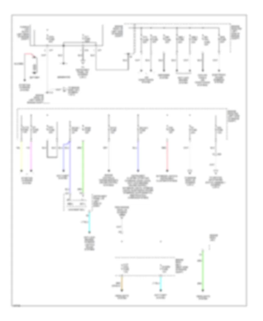
Power Distribution Wiring Diagram (1 of 3) for Toyota Yaris L 2014
List of elements for Power Distribution Wiring Diagram (1 of 3) for Toyota Yaris L 2014:
- A77
- A78
- Abs 1 fuse 50a
- Abs 2 fuse 30a
- Ad8
- Air conditioning system
- Alt fuse 120a
- Alt-s fuse 7.5a
- Am2 fuse 7.5a
- Anti-lock brakes system
- Anti-lock brakes, interior lights & sound systems
- Anti-theft system
- Battery
- Bcyl
- Becu
- C21
- Cooling fans & air conditioning systems
- Dcc fuse 30a
- Def fuse 30a
- Defogger system
- Dome fuse 15a
- Ecu-b 1 fuse 5a
- Ecu-b 2 fuse 5a
- Electronic power steering system
- Engine controls, transmissions & cruise control systems
- Engine room j/b (left side of engine compt)
- Engine room j/b 2
- Engine room r/b (left side of engine compt)
- Engine room r/b 2 (right side of engine compt)
- Eps fuse 50a
- Etcs fuse 10a
- Exterior lights & instrument cluster systems
- From engine room j/b (diagram 1 of 3)
- Fusible link block (left rear of engine compt)
- Generator
- H-lp main fuse 7.5a
- Haz fuse 15a
- Headlights system
- Htr fuse 40a
- Instrument panel j/b (left side of dash)
- Main body ecu
- Main fuse 80a
- Ptc fuse 80a
- R/i fuse 50a
- Rdi fan fuse 30a
- Red
- S-horn fuse 10a
- St fuse 30a
- Starting/ charging system
- To engine room j/b (diagram 3 of 3)
- To engine room j/b 2 (diagram 1 of 3)
- To ignition or starter switch assembly (diagram 2 of 3)
- To instrument panel j/b (diagram 3 of 3)
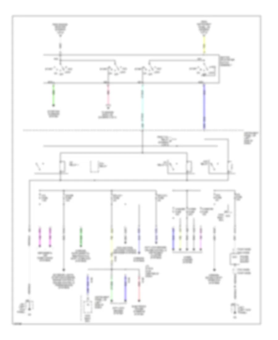
Power Distribution Wiring Diagram (2 of 3) for Toyota Yaris L 2014
List of elements for Power Distribution Wiring Diagram (2 of 3) for Toyota Yaris L 2014:
- (tmc made)
- (tmmf made)
- A/c fuse 7.5a
- A11
- A29
- A40
- A49
- A51
- A54
- Acc
- Acc fuse 5a
- Acc relay
- Am1
- Am2
- Anti-lock brakes system
- Anti-lock brakes, cruise control & instrument cluster systems
- B13
- B37
- C14
- C15
- C27
- C32
- Cig fuse 15a
- Cooling fans, air conditioning & defogger systems
- D148
- D149
- D16
- D32
- Defogger & air conditioning systems
- Ecu-ig 1 fuse 5a
- Ecu-ig 2 fuse 5a
- Electronic power steering system
- Exterior lights, starting/charging, engine controls, cruise control & transmissions systems
- From engine room r/b (diagram 1 of 3)
- From instrument panel j/b (diagram 3 of 3)
- From tail relay g (diagram 3 of 3)
- Gauge fuse 10a
- Ig1
- Ig1 relay 1
- Ig1 relay 2
- Ig2
- Ignition or starter switch assembly
- Instrument panel j/b (left side of dash)
- J/b 7 (left kick panel)
- J/c d148 & d149 (center of dash)
- Lock
- Main body ecu
- Mirrors, sound & shift interlock systems
- Off
- On off
- P/w relay
- Pnk
- Power outlet socket
- Red
- St2
- Start
- Starting/ charging system
- To engine room j/b (diagram 3 of 3)
- Warning systems
- Washer fuse 15a
- Wiper fuse 20a
- Wiper rr fuse 15a
- Wiper/ washer system
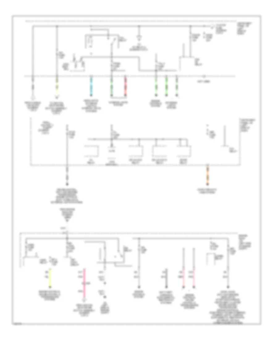
Power Distribution Wiring Diagram (3 of 3) for Toyota Yaris L 2014
List of elements for Power Distribution Wiring Diagram (3 of 3) for Toyota Yaris L 2014:
- (not used)
- A19
- A2 (left side of engine compt)
- A35
- A50
- A56
- Ad8
- Altb
- Am1 fuse 7.5a
- B40
- Bk/dr relay
- C/open relay
- C12
- Computer data lines system
- Cruise control, anti-lock brakes, transmissions, engine controls, shift interlock & exterior lights systems
- D/l fuse 25a
- D/l relay
- D10
- D17
- D19
- Door fuse 20a
- Dr unlock d relay
- Dr unlock relay
- E10
- Efi 3 fuse 7.5a
- Efi main fuse 20a
- Efi main relay
- Engine controls system
- Engine controls, cruise control & transmissions systems
- Engine room j/b (left side of engine compt)
- Exterior lights system
- Fog fr fuse 15a
- Fog fr relay
- From engine room r/b (diagram 1 of 3)
- From fog fr h fuse (diagram 3 of 3)
- From fusible link block (diagram 1 of 3)
- From ignition or starter switch assembly (diagram 2 of 3)
- Headlights, exterior lights & interior lights systems
- Horn fuse 10a
- Horn relay
- Ig2 fuse 10a
- Ig2 relay
- Ign fuse 15a
- Instrument panel j/b (left side of dash)
- Interior lights system
- Main body ecu
- Met fuse 7.5a
- Obd fuse 7.5a
- P/w relay
- Panel fuse 5a
- Pnk
- Red
- Stop fuse 7.5a
- Tail 2 fuse 10a
- Tail relay
- Tlh
- To ig1 relay 2 (diagram 2 of 3)
- To ignition or starter switch assembly (diagram 2 of 3)
- To stop fuse (diagram 3 of 3)
- Trly
POWER DOOR LOCKS
Power Door Locks Wiring Diagram (1 of 2) for Toyota Yaris L 2014
List of elements for Power Door Locks Wiring Diagram (1 of 2) for Toyota Yaris L 2014:
- (left side of dash) instrument panel j/b
- 3 door
- 5 door
- A40
- A54
- Acc
- Acc fuse 5a
- Act+
- Act-
- Actd
- Bcty
- Bcyl
- Becu
- Bk/dr relay
- C21
- Canh
- Canl
- Computer data lines system
- D/l fuse 25a
- D/l relay
- D11
- D12
- D143
- D148
- D149
- D24
- D25
- D26
- D35
- D36
- Dome fuse 15a
- Door lock control switch
- Dr unlock d relay
- Dr unlock relay
- Ecu-b fuse 5a
- Ecu-ig 1 fuse 5a
- Engine room r/b (left side of engine compt)
- Fd3
- Flcy
- Frcy
- Gd3
- Gnd1
- Hj2
- Hot at all times
- Hot in on or acc
- Hot in on or start
- Ile
- Interior lights system
- J/b 7 (left kick panel)
- J/b 8 (right kick panel)
- J/c d148 & d149 (center of dash)
- J/c d148 (center of dash)
- Jd6
- Ksw
- Left door control switch assembly
- Left rear door w/ motor lock assembly (5 door)
- Lock
- Lrcy
- Lsfl
- Lsfr
- Lsr
- Lssr
- Main body ecu (left side of dash)
- Pnk
- Power window regulator master switch assembly
- Prg
- Rda
- Red
- Right door control switch assembly
- Right rear door w/ motor lock assembly (5 door)
- Rj1
- Tion detec- unlock
- Tr+
- Ul1
- Ul2
- Ul3
- Unlock
- W/ power window
- W/o power window
Power Door Locks Wiring Diagram (2 of 2) for Toyota Yaris L 2014
List of elements for Power Door Locks Wiring Diagram (2 of 2) for Toyota Yaris L 2014:
- (left side of dash) instrument panel j/b
- A17
- A39
- Back door key switch (w/o wireless door lock control)
- Back door lock assembly (base of back door)
- C36
- D21
- Detection unlock
- Door control receiver (w/o tire pressure warning system) (base of left "d" pillar)
- Fd3
- Gd3
- Gnd
- Instrument panel j/b (left side of dash)
- J/b 7 (left kick panel)
- J/b 8 (right kick panel)
- J4 (left "c" pillar)
- J68
- J69
- Jd6
- Left front door courtesy light
- Left front door w/ motor lock assembly
- Left rear door courtesy light switch assembly (5 door)
- Lock key
- Lssr
- Pnk
- Prg
- Rda
- Red
- Right front door courtesy light switch assembly
- Right front door w/ motor lock assembly
- Right rear door courtesy light switch assembly (5 door)
- Sj1
- St1
- Switch assembly
- T1 (right side of tailgate)
- Tire pressure warning ecu & receiver (w/ tire pressure warning system) (left "c" pillar)
- Un-lock warning switch assembly (left side of dash)
- Unlock key
- W/ back door opener
- W/ tire pressure warning system
- W/o back door opener
- W/o tire pressure warning system
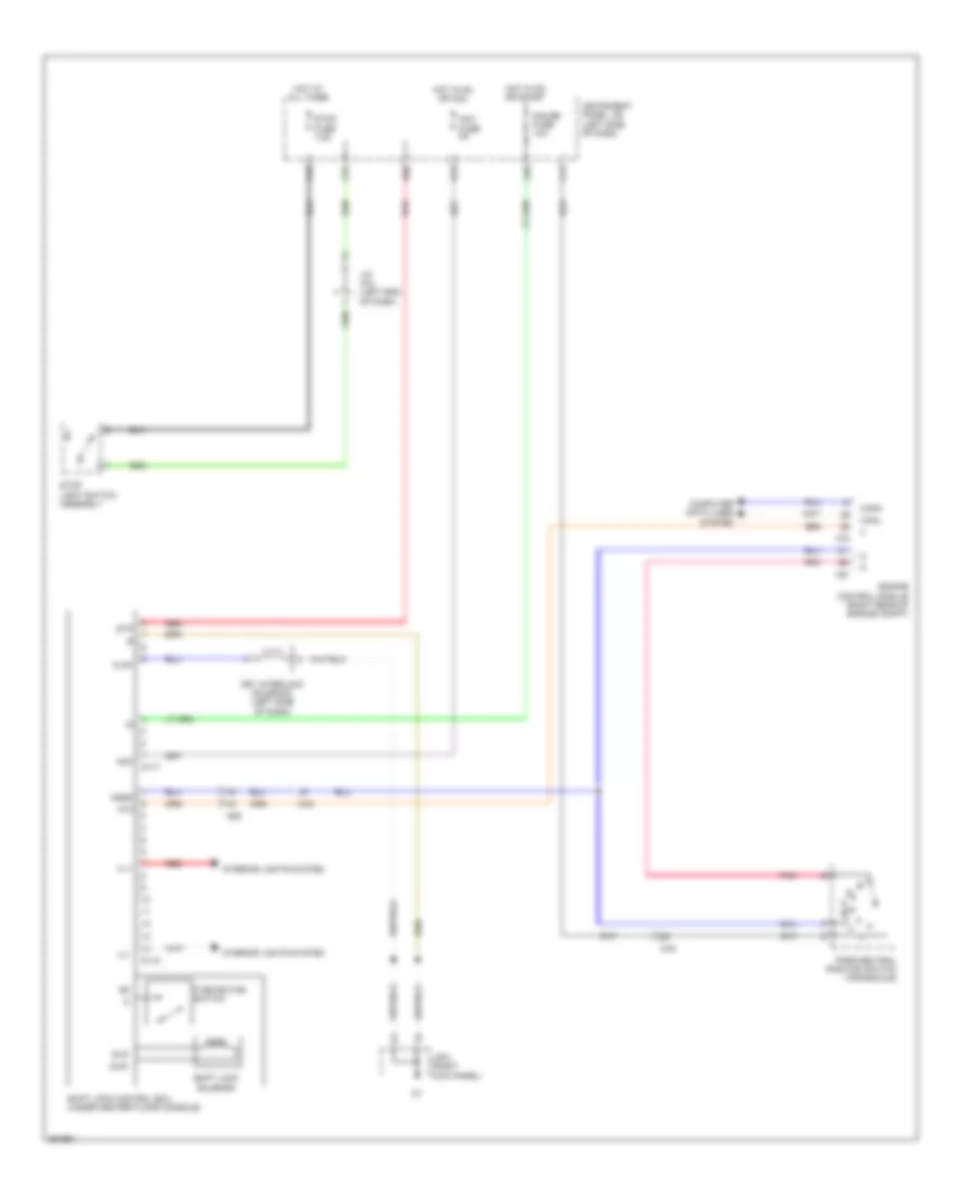
POWER MIRRORS
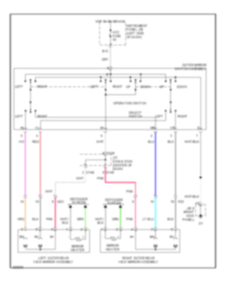
Power Mirrors Wiring Diagram for Toyota Yaris L 2014
List of elements for Power Mirrors Wiring Diagram for Toyota Yaris L 2014:
- Acc fuse 5a
- B13
- D148
- D149
- Defogger system
- Down
- Fd3
- Gd3
- Hot in on or acc
- Instrument panel j/b (left side of dash)
- J/b 8 (right kick panel)
- J/c d148 & d149 (center of dash)
- Left
- Left outer rear view mirror assembly
- Mirror heater
- Operation switch
- Outer mirror switch assembly
- Pnk
- Red
- Right
- Right outer rear view mirror assembly
- Select switch
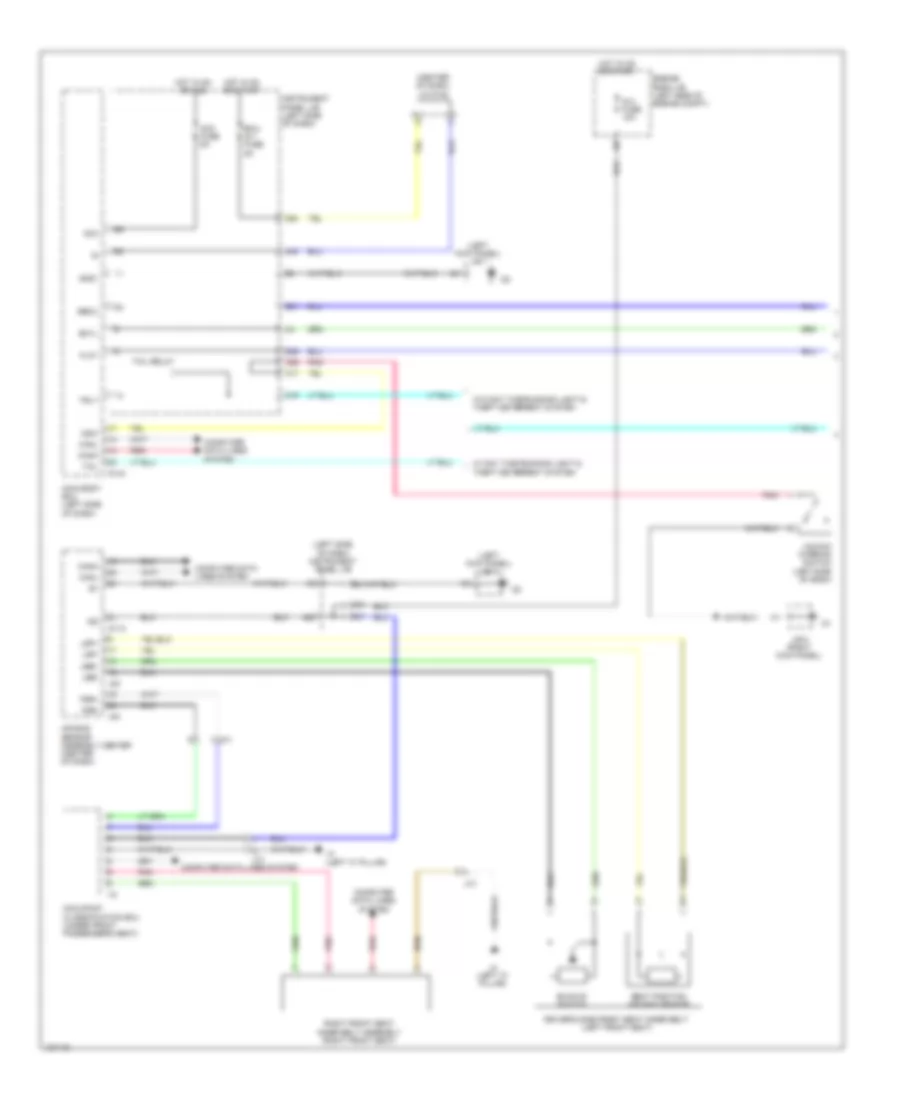
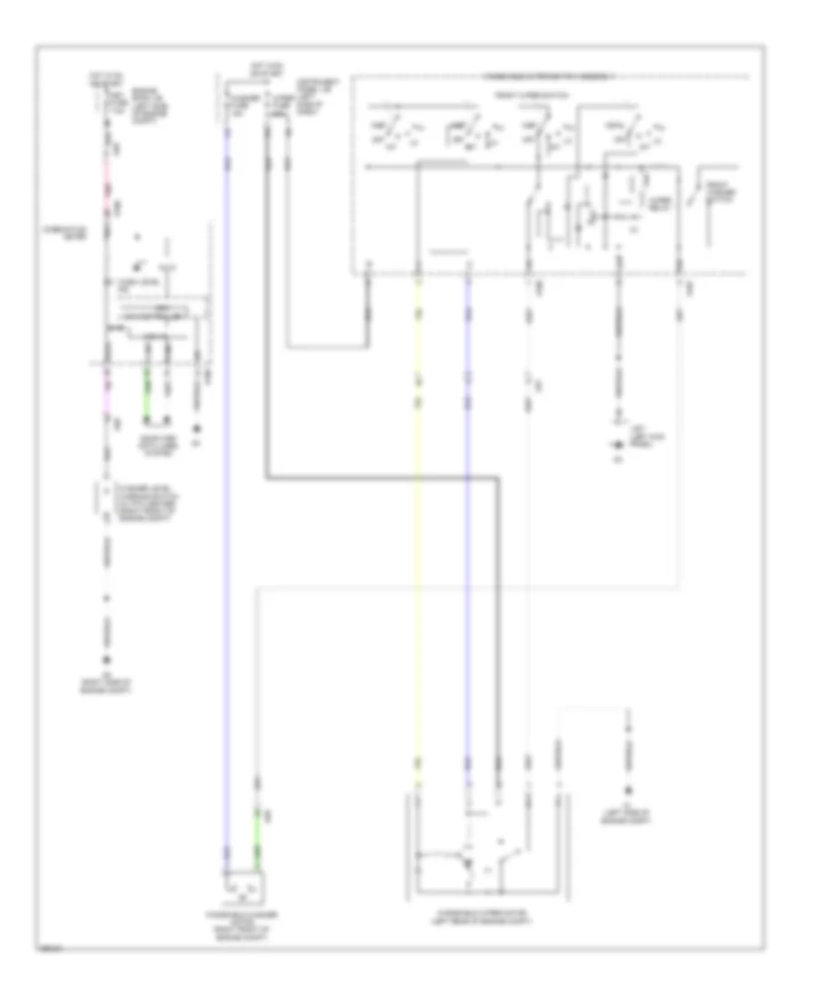
POWER WINDOWS
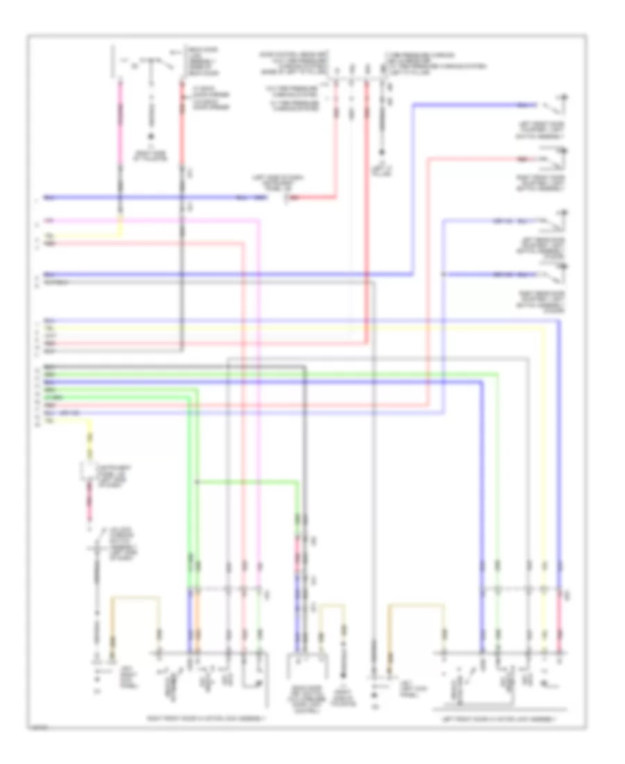
Power Windows Wiring Diagram, with Rear Power Windows for Toyota Yaris L 2014
List of elements for Power Windows Wiring Diagram, with Rear Power Windows for Toyota Yaris L 2014:
- A13
- A14
- A31
- A40
- A54
- A78
- Acc
- Acc fuse 5a
- Alt fuse 120a
- Bcyl
- Becu
- C21
- D143
- D36
- Dome fuse 15a
- Door locks system
- Door p fuse 20a
- Door r/l fuse 20a
- Door r/r fuse 20a
- Down
- Ecu-b fuse 5a
- Ecu-ig 1 fuse 5a
- Engine room r/b (left side of engine compt)
- Fd3
- Flcy
- Fusible link block assembly (left rear of engine compt)
- Gd3
- Gd4
- Gnd1
- Hj2
- Hot at all times
- Hot in on or acc
- Hot in on or start
- Instrument panel j/b (left side of dash)
- J/b 7 (left kick panel)
- J/c d148 (center of dash)
- Jd5
- Jd7
- Koff
- Left front door courtesy light switch assembly
- Left front power window regulator motor assembly
- Left rear power window regulator motor assembly
- Left rear power window regulator switch assembly
- Main body ecu
- P/w fuse 30a
- P/w relay
- Pnk
- Power window regulator master switch assembly
- Red
- Right front power window regulator motor assembly
- Right front power window regulator switch down assembly
- Right rear power window regulator motor assembly
- Right rear power window regulator switch assembly
- Rj1
Power Windows Wiring Diagram, without Rear Power Windows for Toyota Yaris L 2014
List of elements for Power Windows Wiring Diagram, without Rear Power Windows for Toyota Yaris L 2014:
- A13
- A14
- A31
- A40
- A54
- A78
- Acc
- Acc fuse 5a
- Alt fuse 120a
- Bcyl
- Becu
- C21
- D143
- D36
- Dome fuse 15a
- Door locks system
- Door p fuse 20a
- Down
- Ecu-b fuse 5a
- Ecu-ig fuse 5a
- Engine room r/b (left side of engine compt)
- Fd3
- Flcy
- Fusible link block assembly (left rear of engine compt)
- Gd3
- Gnd1
- Hot at all times
- Hot in on or acc
- Hot in on or start
- Instrument panel j/b (left side of dash)
- J/b 7 (left kick panel)
- J/c d148 (center of dash)
- Koff
- Left front door courtesy light switch assembly
- Left front power window regulator motor assembly
- Main body ecu
- P/w fuse 30a
- P/w relay
- Pnk
- Power window regulator master switch assembly
- Right front power window regulator motor assembly
- Right front power window regulator switch assembly
RADIO
Radio Wiring Diagram (1 of 2) for Toyota Yaris L 2014
List of elements for Radio Wiring Diagram (1 of 2) for Toyota Yaris L 2014:
- A16
- Acc fuse 5a
- Adpg
- Agnd
- Alto
- Amplifier microphone assembly (w/ microphone)
- Antenna
- Antenna amplifier (center of dash)
- Ar0
- Asgn
- Au1
- Au2
- Auxo
- B13
- B15
- Combination meter assembly
- Cpu
- D100
- D103
- D134
- D150
- Dome fuse 15a
- Eau
- Engine room r/b (left side of engine compt)
- Hot at all times
- Hot in on or acc
- I/f
- Instrument panel j/b (left side of dash)
- Left steering pad switch
- Macc
- Mco+
- Mco-
- Min+
- Min-
- Mode
- Nca
- Pnk
- Radio receiver assembly
- Red
- Seek+
- Seek-
- Sgnd
- Sns2
- Spd
- Spiral w/ sensor cable sub-assembly
- Steering pad switch assembly
- Stereo jack adapter assembly 1
- Sw1
- Sw2
- Swg
- V12
- Va-
- Val+
- Var+
- Vol+
- Vol-
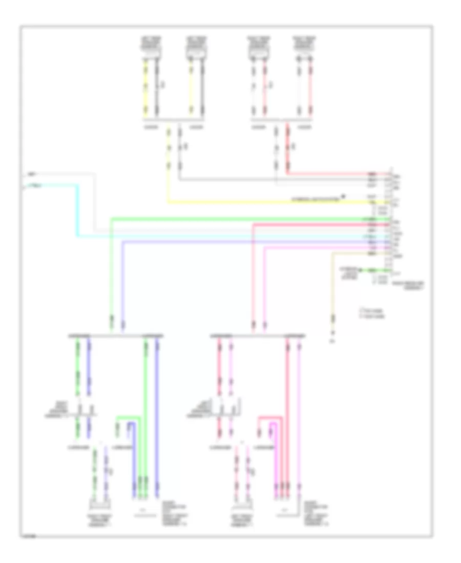
Radio Wiring Diagram (2 of 2) for Toyota Yaris L 2014
List of elements for Radio Wiring Diagram (2 of 2) for Toyota Yaris L 2014:
- +b1
- 3-door
- 4 speaker
- 5-door
- 6 speaker
- Acc1
- D132
- D133
- D153
- D154
- Fd3
- Fl+
- Fl-
- Fr+
- Fr-
- Gd3
- Gnd1
- Hj2
- Ill+
- Ill-
- Interior lights system
- Jd5
- Jd6
- Left front speaker assembly 1
- Left front speaker assembly 2
- Left rear speaker assembly
- Pnk
- Radio receiver assembly
- Red
- Right front speaker assembly 1
- Right front speaker assembly 2
- Right rear speaker assembly
- Rj1
- Rl+
- Rl-
- Rr+
- Rr-
- Short connector d151 (right front speaker assembly 2)
- Short connector d152 (left front speaker assembly 2)
- Tmc made
- Tmmf made
- Twl+
- Twl-
- Twr+
- Twr-
SHIFT INTERLOCK
Shift Interlock Wiring Diagram for Toyota Yaris L 2014
List of elements for Shift Interlock Wiring Diagram for Toyota Yaris L 2014:
- A49
- A72
- Acc
- Acc fuse 5a
- Ad8
- At3
- B13
- B30
- C12
- C14
- C25
- C51
- Ca3
- Canh
- Canl
- Computer data lines system
- D117
- D118
- Engine control module (right rear of engine compt)
- Gauge fuse 10a
- Hot at all times
- Hot in on or acc
- Hot in on or start
- Ill+
- Ill-
- Instrument panel j/b (left side of dash)
- Interior lights system
- J/b 8 (right kick panel)
- J/c a74 (left end of dash)
- Key interlock solenoid (left side of dash)
- Kls+
- N d
- Nssd
- P detection switch
- Park/neutral position switch (transaxle)
- Pnk
- Red
- Shift lock control ecu (under center floor console)
- Shift lock solenoid
- Sls+
- Sls-
- Stop fuse 7.5a
- Stop light switch assembly
- Stp
STARTING/CHARGING
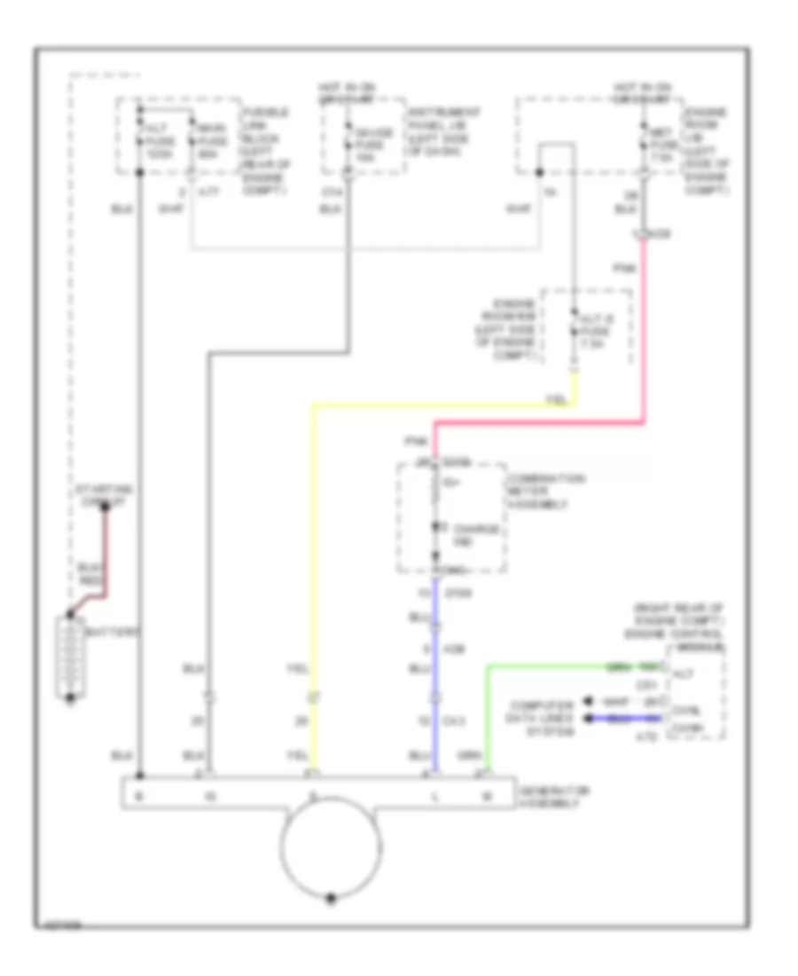
Charging Wiring Diagram for Toyota Yaris L 2014
List of elements for Charging Wiring Diagram for Toyota Yaris L 2014:
- (right rear of engine compt) engine control module
- A72
- A77
- Ad8
- Alt
- Alt fuse 120a
- Alt-s fuse 7.5a
- Battery
- C14
- C51
- Ca3
- Canh
- Canl
- Charge ind
- Chg-
- Combination meter assembly
- Computer data lines system
- D100
- Engine room j/b (left side of engine compt)
- Engine room r/b (left side of engine compt)
- Fusible link block (left rear of engine compt)
- Gauge fuse 10a
- Generator assembly
- Hot in on or start
- Ig+
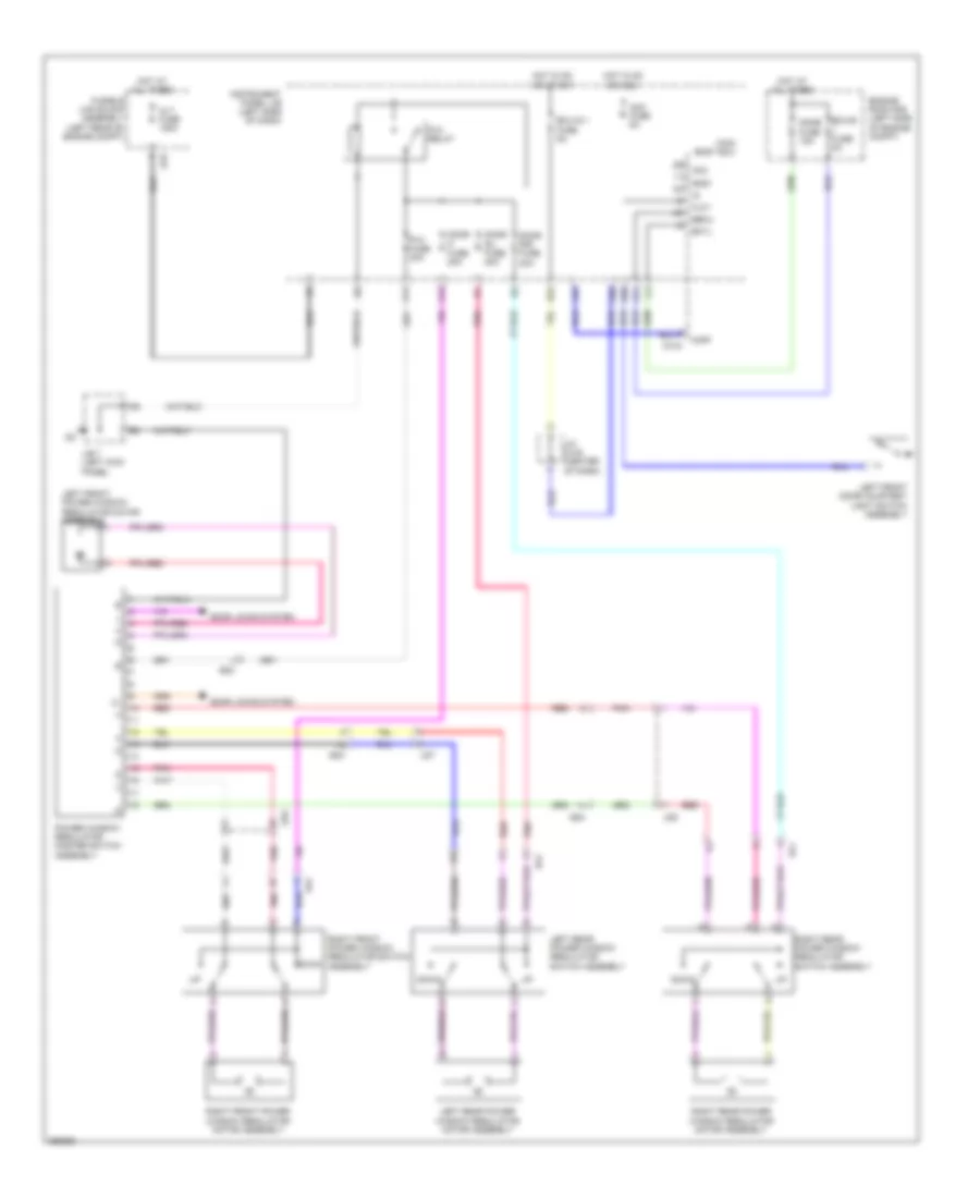
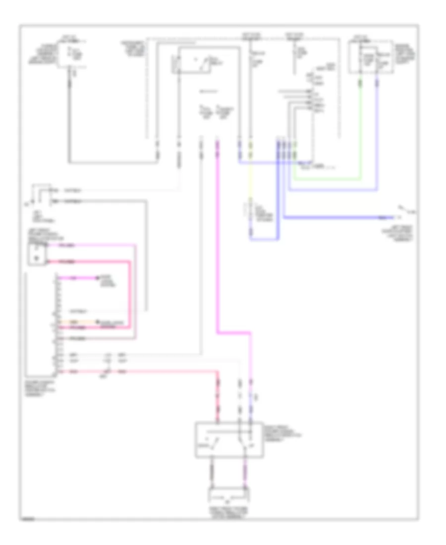
- Instrument panel j/b (left side of dash)
- Main fuse 80a
- Met fuse 7.5a
- Pnk
- Starting circuit
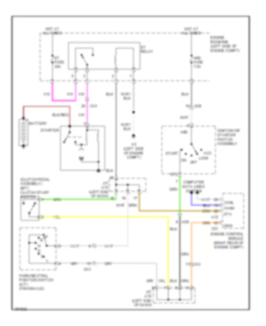
Starting Wiring Diagram for Toyota Yaris L 2014
List of elements for Starting Wiring Diagram for Toyota Yaris L 2014:
- (clutch pedal assembly) (m/t) clutch start switch
- A2 (left side of engine compt)
- A72
- Acc
- Ad8
- Am2
- Am2 fuse 7.5a
- Battery
- C51
- Ca3
- Canh
- Canl
- Computer data lines system
- Engine control module (right rear of engine compt)
- Engine room r/b (left side of engine compt)
- Hot at all times
- Ignition or starter switch assembly
- J/c a74 (left end of dash)
- J/c a76 (left end of dash)
- Lock
- Nsw
- On off
- Park/neutral position switch (a/t) (transaxle)
- St fuse 30a
- St relay
- St2
- Sta
- Start
- Starter
SUPPLEMENTAL RESTRAINTS
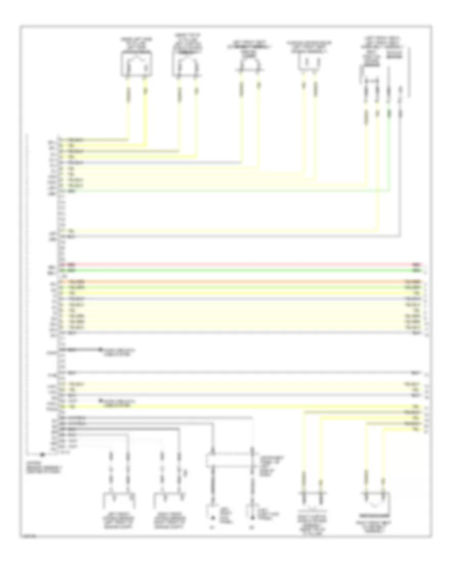
Supplemental Restraints Wiring Diagram (1 of 3) for Toyota Yaris L 2014
List of elements for Supplemental Restraints Wiring Diagram (1 of 3) for Toyota Yaris L 2014:
- (left front seat) left front seat inner belt assembly
- (near left side "b" pillar) left side air bag squib
- (near top of "c" pillar) left curtain shield air bag assembly
- +sl
- +sr
- -sl
- -sr
- Ad6
- Air bag sensor assembly (center of dash)
- Bbl+
- Bbl-
- Buckle switch
- Canh
- Canl
- Computer data lines system
- Cushion air bag squib (left front seat air bag assembly)
- D112
- D2+
- D2-
- Dk+
- Dk-
- Fcd+
- Fcd-
- Icl+
- Icl-
- Icr+
- Icr-
- Ig2
- Instrument panel j/b (left side of dash)
- J/b 7 (left kick panel)
- J/b 8 (right kick panel)
- J83
- Lbe+
- Lbe-
- Left front air bag sensor (left front of engine compt)
- Left front seat outer belt assembly
- Lsp+
- Lsp-
- P-ab
- P2+
- P2-
- Paon
- Pl+
- Pl-
- Preten- sioner
- Pretensioner
- Red
- Right curtain shield air bag assembly (near top of "c" pillar)
- Right front air bag sensor (right front of engine compt)
- Right front seat outer belt assembly
- Seat position air bag sensor
- Sfl+
- Sfl-
- Vhp+
- Vhp-
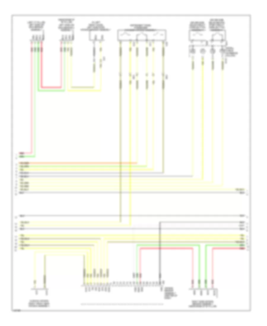
Supplemental Restraints Wiring Diagram (2 of 3) for Toyota Yaris L 2014
List of elements for Supplemental Restraints Wiring Diagram (2 of 3) for Toyota Yaris L 2014:
- (in left front door) left side door air bag sensor assembly
- (left "c" pillar) left side air bag sensor assembly
- (near base of "b" pillar)
- Air bag sensor assembly (center of dash)
- Bbl+
- Bbl-
- Bbr+
- Bbr-
- Bcl+
- Bcl-
- Bcr+
- Bcr-
- Bdl+
- Bdl-
- Cushion air bag (right front seat air bag assembly)
- D113
- Dq3
- Dq4
- Driver side squib circuit (horn button assembly)
- Driver side squib second step circuit (horn button assembly)
- Fcp+
- Fcp-
- Fsr+
- Fsr-
- Gj1
- Icr+
- Icr-
- Instrument panel passenger w/0 door air bag assembly
- J84
- Left side air bag sensor 2 assembly
- Pr+
- Pr-
- Q10
- Q11
- Q12
- Red
- Right side air bag sensor assembly (near base of 'b" pillar)
- Sfr+
- Sfr-
- Spiral cable (steering column)
- W10
- W11
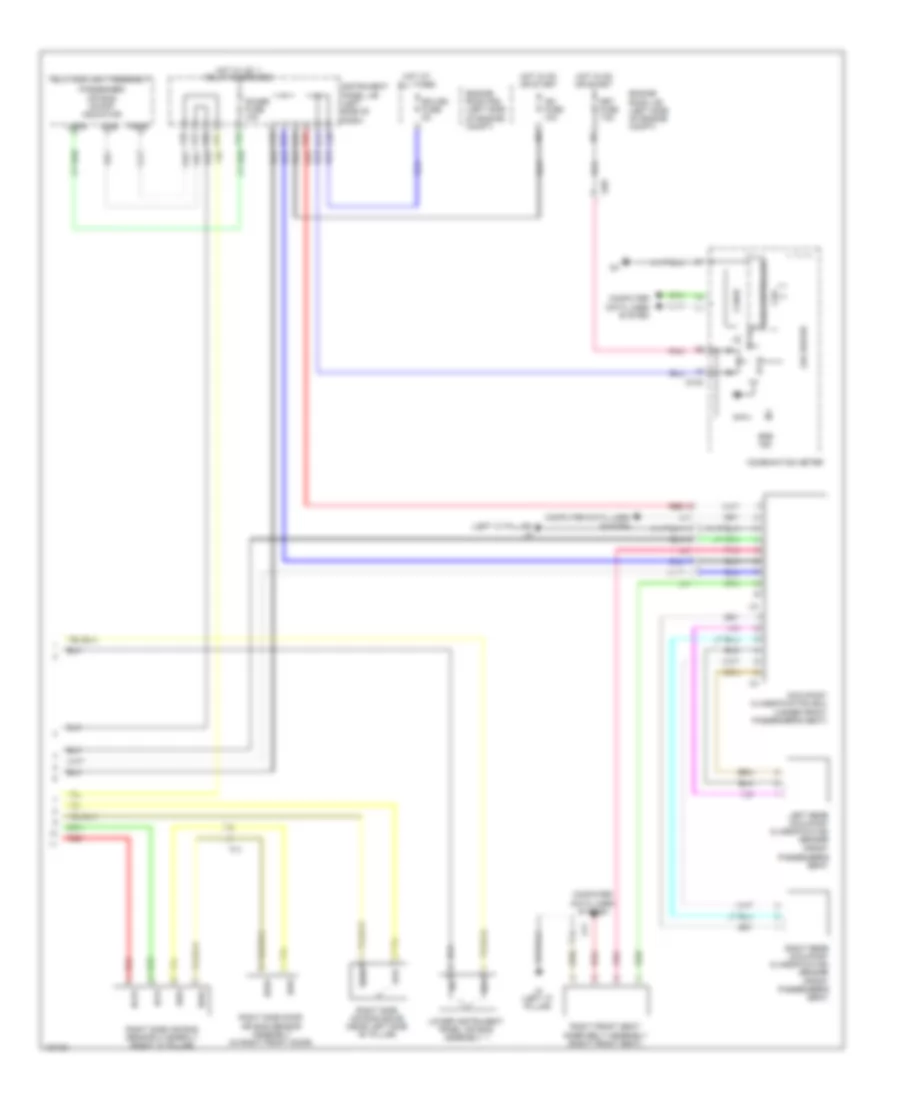
Supplemental Restraints Wiring Diagram (3 of 3) for Toyota Yaris L 2014
List of elements for Supplemental Restraints Wiring Diagram (3 of 3) for Toyota Yaris L 2014:
- (left "c" pillar) j4
- 5v ic
- 5v+b
- A21
- A24
- A26
- A30
- A45
- A49
- Ad8
- B14
- Bcr+
- Bcr-
- Bdr+
- Bdr-
- C31
- C36
- Can controller
- Can i/f
- Combination meter
- Computer data lines system
- Cpu
- D100
- D30
- D31
- Dk+
- Dk-
- Ecu-b2 fuse 5a
- Engine room j/b (left side of engine compt)
- Engine room r/b (left side of engine compt)
- Fj1
- Gauge fuse 10a
- Hot at all times
- Hot in on or start
- Hot w/ ig1 1 relay energized
- Ig2 fuse 10a
- Instrument panel j/b (left side of dash)
- J4 (left "c" pillar)
- Jx1
- Lapb
- Led driver
- Left rear occupant classification sensor (front
- Lower instrument panel air bag assembly 1
- Met fuse 7.5a
- Occupant classification ecu (under front passenger's seat)
- P-ab
- Paon
- Passenger air bag on/off indicator
- Passenger's seat)
- Pnk
- Red
- Right front seat inner belt assembly (right front seat)
- Right rear occupant classification sensor (front passenger's seat)
- Right side air bag sensor 2 assemly (right "c" pillar)
- Right side air bag squib (near left side "b" pillar)
- Right side door air bag sensor assembly (in right front door)
- Sfr+
- Sfr-
- Srs ind
- Telltale light assembly
TRANSMISSION
Transmission Wiring Diagram (1 of 2) for Toyota Yaris L 2014
List of elements for Transmission Wiring Diagram (1 of 2) for Toyota Yaris L 2014:
- (brake pedal mounting bracket) stop light switch assembly
- (left end of dash) j/c a74
- +b2
- A2 (left side of engine compt)
- A72
- Ad8
- Ad9
- B14
- B15
- C12
- C14
- C2 (rear of engine)
- C36
- C39
- C51
- Ca3
- Canh
- Canl
- Computer data lines system
- D19
- E10
- Ecu-b 2 fuse 5a
- Efi main fuse 20a
- Efi main relay
- Efii
- Efio
- Electronically controlled transmission solenoid (transaxle)
- Engine control module (right rear of engine compt)
- Engine room j/b (left side of engine compt)
- Engine room r/b (left side of engine compt)
- Eo1
- Eo4
- Etho
- Etho1
- Gauge fuse 10a
- Hot at all times
- Hot in on or start
- Ig2 fuse 10a
- Igsw
- Imi
- Imo
- Instrument panel j/b (left side of dash)
- Meo1
- Mrel
- Nt+
- Nt-
- Pnk
- Red
- Slt+
- Slt-
- Slu+
- Slu-
- Spd
- St1-
- Sta
- Starting/charging system
- Stop fuse 7.5a
- Stp
- Transmission revolution sensor (turbine)
- Transponder key ecu assembly (engine immobiliser system) (center of dash)
Transmission Wiring Diagram (2 of 2) for Toyota Yaris L 2014
List of elements for Transmission Wiring Diagram (2 of 2) for Toyota Yaris L 2014:
- (left end of dash)
- (left side of engine compt) a2
- 5v ic
- 5v+b
- A70
- A71
- Ad8
- At3
- Brake actuator assembly
- C32
- Ca3
- Can controller
- Can i/f
- Canh
- Canl
- Chk
- Combination meter
- Computer data lines system
- Cpu
- D100
- Ecu-ig 2 fuse 5a
- Engine room j/b (left side of engine compt)
- Hot in on or start
- I/f
- Ig+
- Instrument panel j/b (left side of dash)
- J/c a76
- Malfunction ind lamp
- Met fuse 7.5a
- Nssd
- Park/ neutral position switch (transaxle)
- Pnk
- Red
- Shift lock control ecu (under center floor console)
- Sp1
- Speedometer sensor
- W/ abs
- W/ vsc
- W/o abs
- W/o vsc
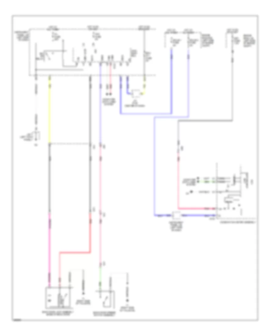
TRUNK, TAILGATE, FUEL DOOR
Back Door Opener Wiring Diagram for Toyota Yaris L 2014
List of elements for Back Door Opener Wiring Diagram for Toyota Yaris L 2014:
- 5v ic
- A40
- A54
- Acc
- Acc fuse 5a
- Ad8
- Altb
- B14
- Back door lock assembly (base of back door)
- Back door opener switch assembly
- Bcty
- Bdsu
- Becu
- Bk/ dr relay
- C21
- C36
- Can controller
- Can i/f
- Canh
- Canl
- Combination meter assembly
- Computer data lines system
- Cpu
- D/l fuse 25a
- D100
- D143
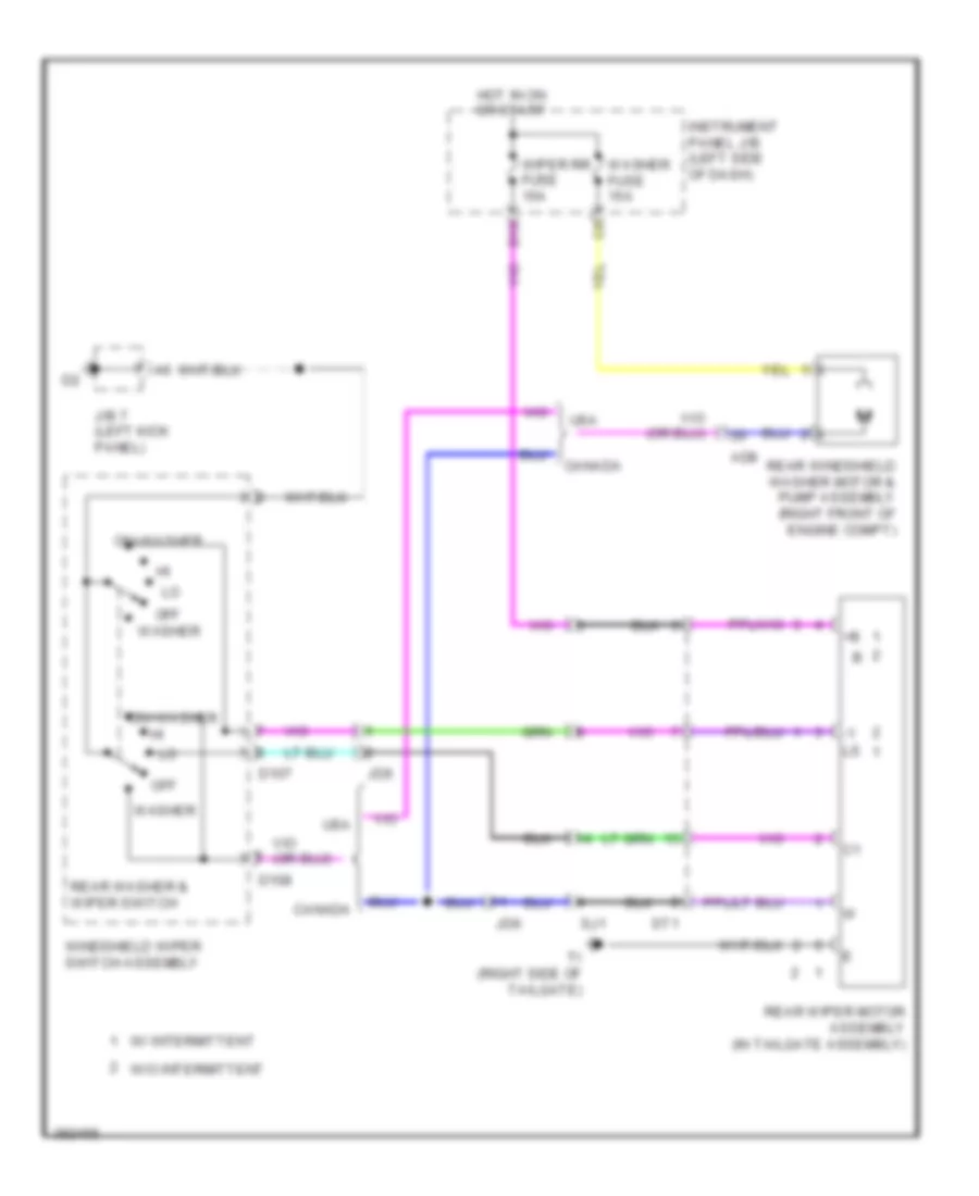
- D35
- Ecu- ig 1 fuse 5a
- Ecu-b 1 fuse 5a
- Ecu-b 2 fuse 5a
- Engine room j/b (left side of engine compt)
- Engine room r/b (left side of engine compt)
- Gnd1
- Hot at all times
- Hot in on or acc
- Hot in on or start
- Ig+
- Instrument panel j/b (left side of dash)
- J/b 7 (left kick panel)
- J/c d148 (center of dash)
- Jd6
- Main body ecu
- Met fuse 7.5a
- Pnk
- Red
- Sj1
- St1
- Switch courtesy
- T1 (right side of tailgate)
- Tr+
WARNING SYSTEMS
Key Reminder & Seat Belt Warning Wiring Diagram (1 of 2) for Toyota Yaris L 2014
List of elements for Key Reminder & Seat Belt Warning Wiring Diagram (1 of 2) for Toyota Yaris L 2014:
- (center of dash) j/c d148
- (left kick panel) j/b 7
- (left side of dash) instrument panel j/b
- A17
- A19
- A39
- A40
- A45
- A54
- Acc
- Acc fuse 5a
- Air bag sensor assembly center (center of dash)
- Bcyl
- Becu
- Buckle switch
- C21
- C31
- Canh
- Canl
- Computer data lines system
- D112
- D143
- D31
- D36
- Driver's side front seat inner belt (left front seat)
- Ecu- ig 1 fuse 5a
- Engine room j/b (left side of engine compt)
- Flcy
- Fsr+
- Fsr-
- Gnd1
- Hot in on or acc
- Hot in on or start
- Ig 2 fuse 10a
- Ig2
- Instrument panel j/b (left side of dash)
- J/b 8 (right kick panel)
- J4 (left "c" pillar)
- J83
- J84
- Jx1
- Ksw
- Lbe+
- Lbe-
- Lsp+
- Lsp-
- Main body ecu (left side of dash)
- Occupant classification ecu (under front passenger's seat)
- Pnk
- Red
- Right front seat inner belt assembly (right front seat)
- Seat position air bag sensor
- Tail
- Tail relay
- Trly
- Unlock warning switch (left side of dash)
- W/ day time running light & theft deterrent system
- W/o day time running light & theft deterrent system
Key Reminder & Seat Belt Warning Wiring Diagram (2 of 2) for Toyota Yaris L 2014
List of elements for Key Reminder & Seat Belt Warning Wiring Diagram (2 of 2) for Toyota Yaris L 2014:
- 5v +b
- 5v ic
- Ad8
- Auto
- B14
- Buzzer
- C36
- Can controller
- Can i/f
- Combination meter assembly
- Computer data lines system
- Cpu
- D100
- Dome fuse 15a
- Door
- Driver's seat belt ind
- Ecu-b 1 fuse 5a
- Ecu-b 2 fuse 5a
- Engine room j/b (left side of engine compt)
- Engine room r/b (left side of engine compt)
- Head
- Headlight dimmer switch assembly
- Hot at all times
- Hot in on or start
- I/f
- Ind
- Instrument panel j/b (left side of dash)
- J/b 7 (left kick panel)
- Led driver
- Left front door courtesy light switch
- Met fuse 7.5a
- Off
- Pnk
- Tail
Tire Pressure Monitoring Wiring Diagram for Toyota Yaris L 2014
List of elements for Tire Pressure Monitoring Wiring Diagram for Toyota Yaris L 2014:
- (center of dash) j/c d148
- (left kick panel) j/b 7
- (right kick panel) j/b 8
- 5v +b
- 5v ic
- A40
- A54
- Acc
- Acc fuse 5a
- Ad8
- B14
- Becu
- C21
- C36
- Can controller
- Can i/f
- Canh
- Canl
- Clsw
- Combination meter assembly
- Computer data lines system
- Cpu
- D100
- D143
- D21
- D32
- Dcyl
- Dome fuse 15a
- Ecu- ig 1 fuse 5a
- Ecu-b 1 fuse 5a
- Ecu-b 2 fuse 5a
- Engine room j/b (left side of engine compt)
- Engine room r/b (left side of engine compt)
- Gnd
- Gnd1
- Hot at all times
- Hot in on or acc
- Hot in on or start
- Instrument panel j/b (left side of dash)
- Int
- J4 (left "c" pillar)
- Jd6
- Led driver
- Main body ecu (left side of dash)
- Met fuse 7.5a
- Pnk
- Prg
- Rda
- Red
- Tire pressure ind
- Tire pressure warning ecu & receiver (door control & tire pressure monitoring system receiver assembly) (left "c" pillar)
- Tire pressure warning reset switch
- W/ wireless door lock control
WIPER/WASHER
Front Wiper/Washer Wiring Diagram for Toyota Yaris L 2014
List of elements for Front Wiper/Washer Wiring Diagram for Toyota Yaris L 2014:
- 5v ic
- 5v+b
- A1 (left side of engine compt)
- A5 (right side of engine compt)
- Ad7
- Ad8
- Can controller
- Can i/f
- Canh
- Canl
- Combination meter
- Computer data lines system
- Cpu
- D100
- D107
- D108
- Engine room j/b (left side of engine compt)
- Front washer switch
- Front wiper switch
- Hot in on or start
- Ig+
- Instrument panel j/b (left side of dash)
- Int
- J/b 7 (left kick panel)
- Met fuse 7.5a
- Mist
- Off
- Pnk
- Wash level ind
- Washer fuse 15a
- Washer level warning switch (w/ ptc heater) (right front of engine compt)
- Windshield washer motor (right front of engine compt)
- Windshield wiper motor (left rear of engine compt)
- Windshield wiper switch assembly
- Wiper fuse 20a
- Wiper relay
- Wlvl
Rear Wiper/Washer Wiring Diagram for Toyota Yaris L 2014
List of elements for Rear Wiper/Washer Wiring Diagram for Toyota Yaris L 2014:
- Ad8
- Canada
- D107
- D108
- D16
- Hot in on or start
- Instrument panel j/b (left side of dash)
- J/b 7 (left kick panel)
- Jd6
- Off
- On+washer
- Rear washer & wiper switch
- Rear windshield washer motor & pump assembly (right front of engine compt)
- Rear wiper motor assembly (in tailgate assembly)
- Sj1
- St1
- Ti (right side of tailgate)
- Usa
- W/ intermittent
- W/o intermittent
- Washer
- Washer fuse 15a
- Windshield wiper switch assembly
- Wiper rr fuse 15a

 Čeština
 Dansk
Dansk Deutsch
 Ελληνικά
 English
 English
 Español
 Suomi
Suomi Français
 Français
 עברית
עברית Hrvatski
 Magyar
 Italiano
 日本語
日本語 한국어
한국어 Nederlands
 Polski
 Português
 Português
 Русский
 Slovenčina
 Slovenščina
 Svenska
 Türkçe
 中文 (中国)