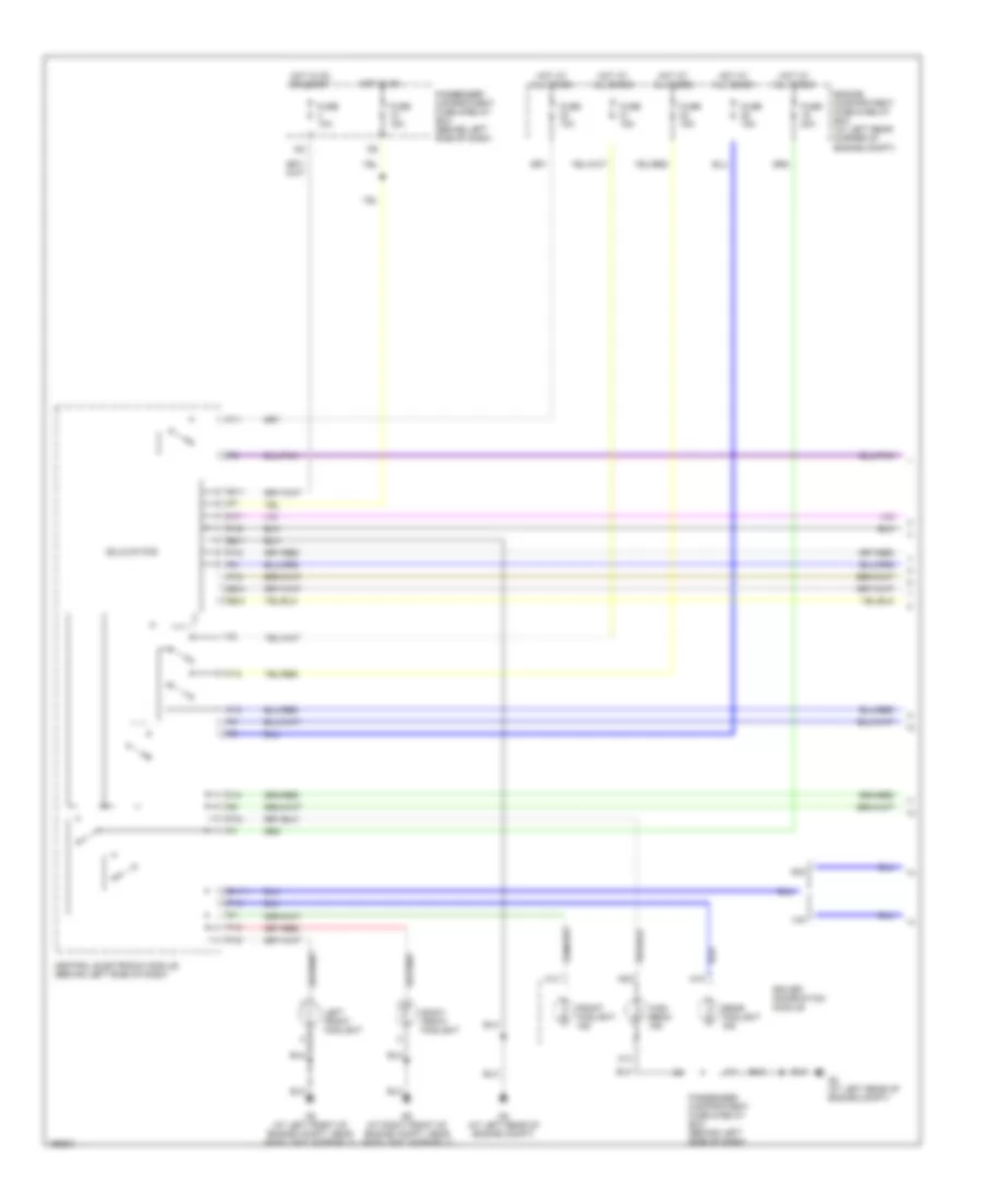
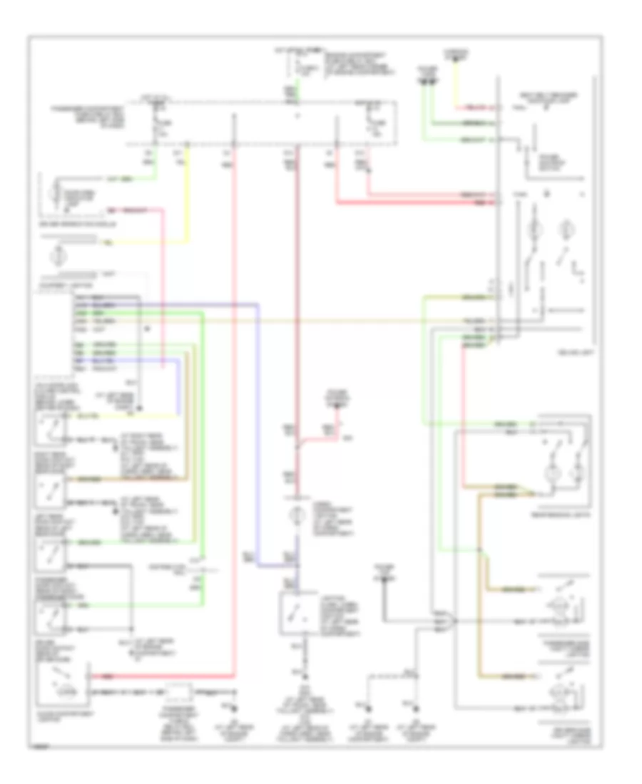
AIR CONDITIONING
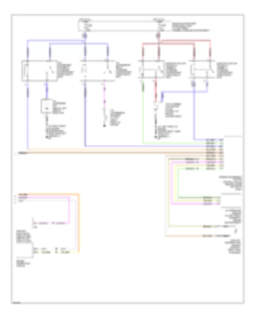
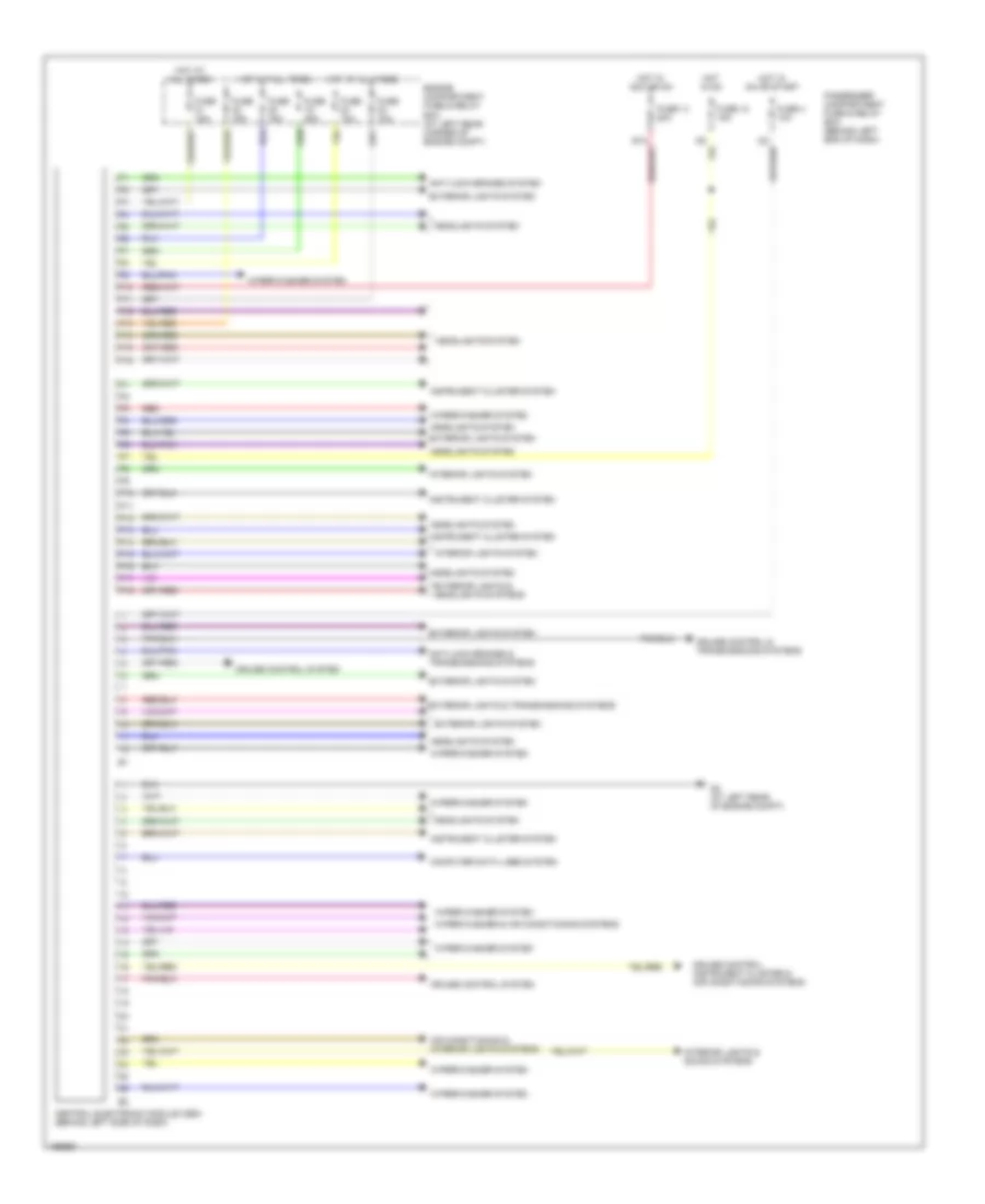
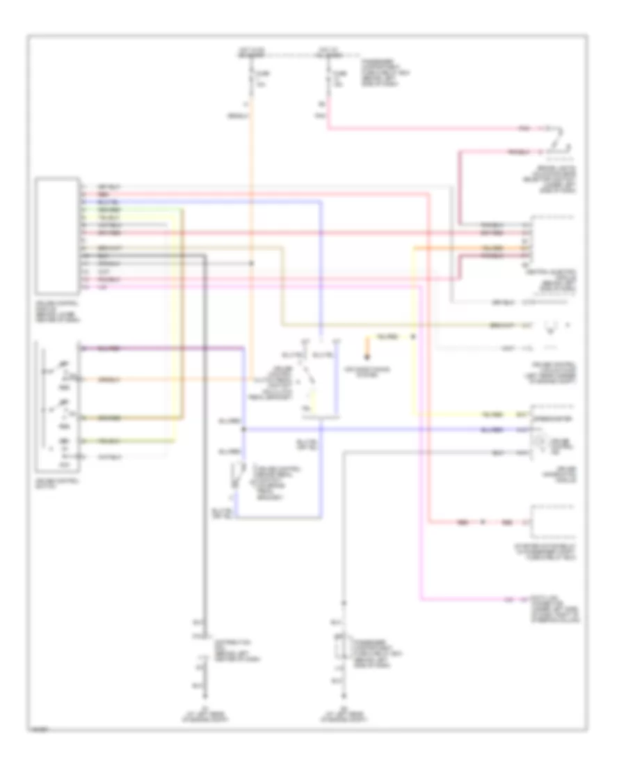
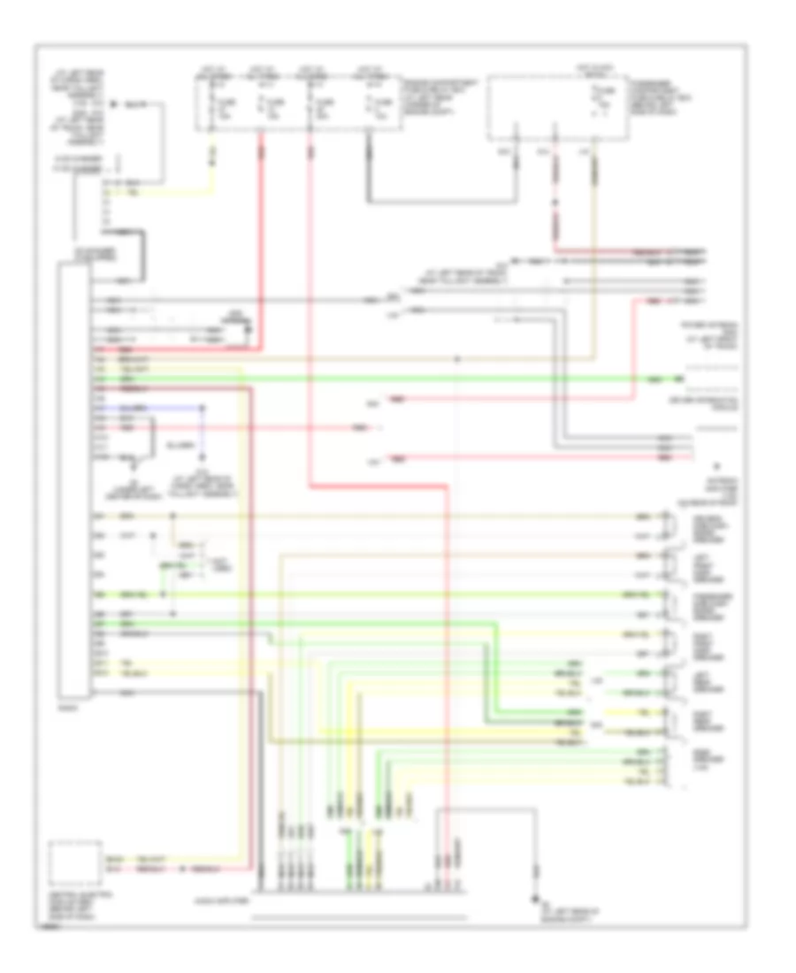
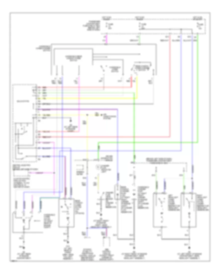
Automatic A/C Wiring Diagram (1 of 2) for Volvo S40 2004
 https://portal-diagnostov.com/license.html
Automotive Electricians Portal FZCO
Automotive Electricians Portal FZCO
https://portal-diagnostov.com/license.html
https://portal-diagnostov.com/license.html
Automotive Electricians Portal FZCO
Automotive Electricians Portal FZCO
List of elements for Automatic A/C Wiring Diagram (1 of 2) for Volvo S40 2004:
- (at left rear of engine compartment) g2
- (at left rear of engine compt) g1
- (under left side of dash, right of steering column) data link connector
- A/c evaporator & a/c outside temperature sensors (behind right side of dash)
- Anti-lock brakes system
- Climate control module (integral to a/c controls, in center of dash)
- Climate control temperature damper (behind center of dash, on left side of hvac assembly)
- Coolant temperature ecc sensor (behind upper right side of dash)
- Defogger system
- Distribution rail (behind left center of dash)
- E10
- Engine compartment fuse & relay box (at left rear corner of engine compartment)
- Fuse 10a
- Fuse 15a
- Fuse 25a
- G1 (at left rear of engine compt)
- Hot at all times
- Hot in on
- Interior lights system
- J14
- Passenger compartment fan max speed relay (behind lower right side of dash)
- Passenger compartment fan motor (under right side of dash, on hvac assembly)
- Passenger compartment fan relay
- Passenger compartment fan speed control module (behind right side of dash, on bottom of hvac assembly)
- Passenger compartment fuse & relay box (behind left side of dash)
- Pnk
- Recirculation damper motor (behind right side of dash, on bottom right of hvac assembly)
- Red
- Seats system
- Solar sensor
- Solid state
- Ventilation/floor/defroster damper motor (behind center of dash, on left side of hvac assembly)
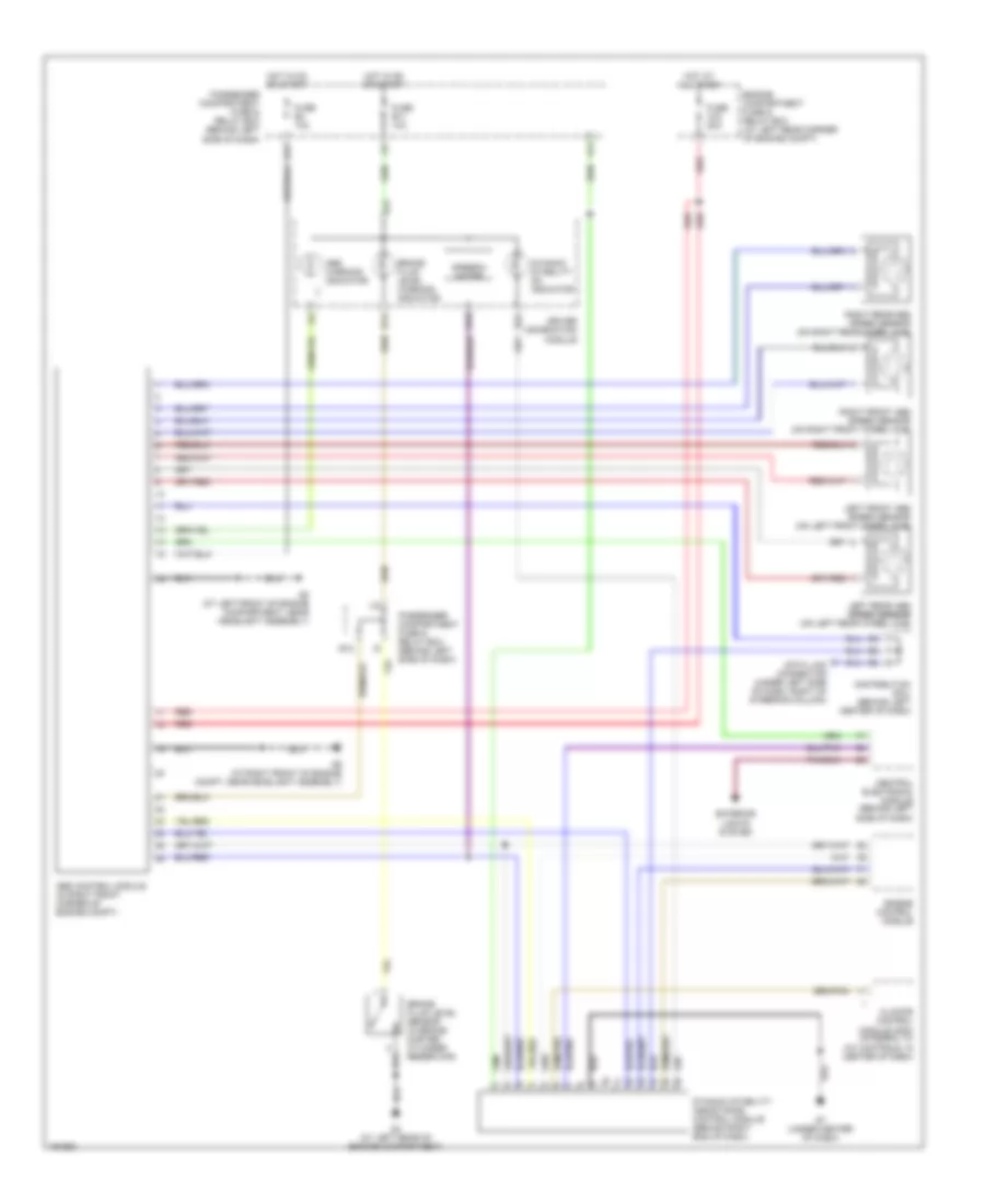
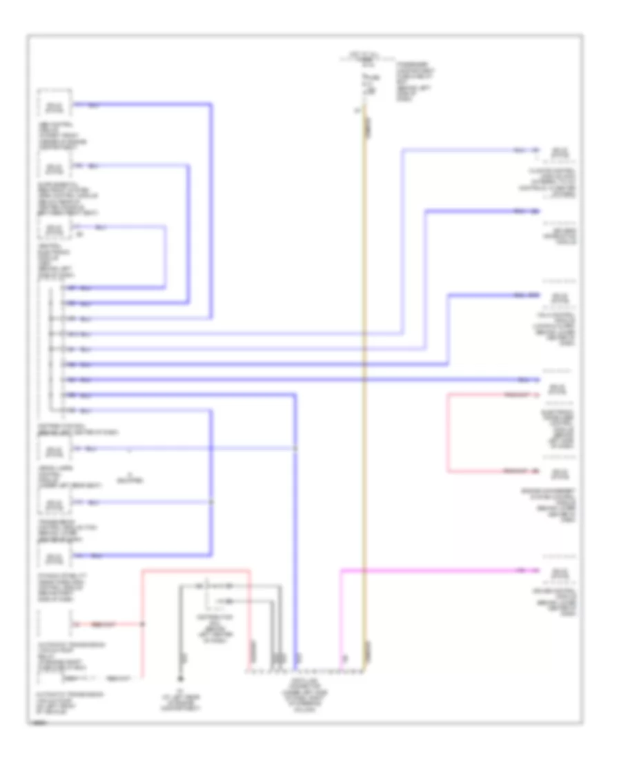
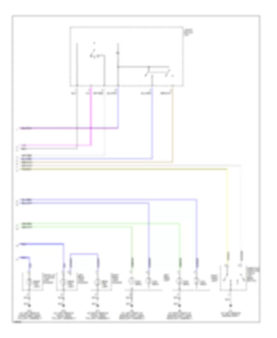
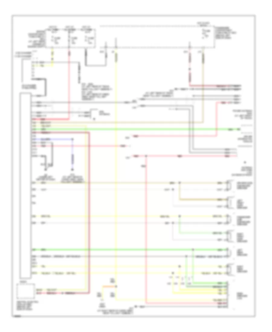
Automatic A/C Wiring Diagram (2 of 2) for Volvo S40 2004
List of elements for Automatic A/C Wiring Diagram (2 of 2) for Volvo S40 2004:
- (at left front of engine compartment, near headlight assembly) g8
- (at right front of engine compartment, near headlight assembly) g9
- A/c compressor relay (in engine compartment fuse & relay box)
- A/c compressor solenoid clutch (right front of engine)
- A/c condenser fan (behind left side of radiator)
- A/c condenser fan relay (in engine compartment fuse & relay box)
- A/c pressure sensor (in left front corner of engine compartment)
- B13
- B15
- Central electronic module (cem) (behind left side of dash)
- Coolant temperature sensor (on right front side of engine)
- Driver information module
- Electric cooling fan relay (speed 1) (in engine compartment fuse & relay box)
- Electric cooling fan relay (speed 2) (in engine compartment fuse & relay box)
- Engine compartment fuse & relay box (at left rear corner of engine compartment)
- Engine management system control module (behind lower center of dash)
- Fuse 20a
- Fuse 30a
- Hot at all times
- Nca
- Red
- Two (2) speed cooling fan motor (in front of engine compartment)
ANTI-LOCK BRAKES
Anti-lock Brakes Wiring Diagram for Volvo S40 2004
List of elements for Anti-lock Brakes Wiring Diagram for Volvo S40 2004:
- A17
- Abs control module (in right front corner of engine compt)
- Abs warning indicator
- B14
- B16
- B22
- Brake fluid level sensor (in brake master cylinder reservoir)
- Brake fluid level warning indicator
- Central electronic module (behind left side of dash)
- Climate control module (ccm) (integral to a/c controls, in center of dash)
- Data link connector (under left side of dash, right of steering column)
- Distribution rail (behind left center of dash)
- Driver information module
- Dynamic stability assistance control module (behind right end of dash)
- Dynamic stability on indicator
- E11
- E12
- Engine compartment fuse & relay box (at left rear corner of engine compt)
- Engine control module
- Exterior lights system
- Fuse a15 50a
- Fuse b11 10a
- Fuse b4 10a
- G4 (at left rear of engine compartment)
- G7 (under center of dash)
- G8 (at left front of engine compartment, near headlight assembly)
- G9 (at right front of engine compt, near headlight assembly)
- Hot at all times
- Hot in on or start
- I10
- I14
- Left front abs speed sensor (on left front wheel hub)
- Left rear abs speed sensor speed sensor (on left rear wheel hub)
- Passenger compartment fuse & relay box (behind left side of dash)
- Red
- Right front abs speed sensor (on right front wheel hub)
- Right rear abs speed sensor (on right rear wheel hub)
- Speedo- meter
ANTI-THEFT
Forced Entry Wiring Diagram for Volvo S40 2004
List of elements for Forced Entry Wiring Diagram for Volvo S40 2004:
- (at front center of engine compt, integral to hood latch)
- (at left front of engine compt, near headlight assembly) g8
- (at left rear of engine compartment) g1
- (at left rear of trunk, near taillight assembly) (s40) g10 (at left rear of cargo area, near taillight assembly) (v40) g12
- (at right rear of trunk, near taillight assembly) (s40) g11 (at left rear of cargo area, near taillight assembly)
- (v40) g12
- A10
- A12
- A13
- A16
- A18
- A19
- A20
- A22
- A23
- A24
- A25
- A26
- Alarm siren (front of engine compt)
- B10
- B11
- B14
- B15
- B16
- B19
- C10
- Cargo compartment lighting/ alarm contact (at left rear of cargo compt)
- Computer data lines system
- Distribution rail (behind left center of dash)
- Driver door contact (rear of driver door)
- Driver's door central locking switch
- Driver's door lock switch
- Driver's door power windows/ mirrors control module
- E10
- Engine compartment fuse & relay box (at left rear corner of engine compt)
- Exterior lights system
- F10
- Fuse 10a
- Fuse 15a
- Fuse 20a
- G1 (at left rear of engine compartment)
- G15
- G9 (at right front of engine compartment, near headlight assembly)
- Glass breakage sensor (on roof, at center of windshield header)
- Hood alarm contact
- Hot at all times
- Hot in on
- Hot in on or start
- Interior lights system
- Key- inserted warning contact
- Left rear door contact (rear of left rear door)
- Passenger compartment fuse & relay box (behind left side of dash)
- Passenger door central locking switch
- Passenger door contact (rear of front passenger door)
- Pnk
- Red
- Right rear door contact (rear of right rear door)
- Ultrasonic glass breakage sensor (below right side of dash)
- Vgla control module (behind lower center of dash)
- Vgla receiver (in rear of engine compt)
Immobilizer Wiring Diagram for Volvo S40 2004
List of elements for Immobilizer Wiring Diagram for Volvo S40 2004:
- (at left rear of engine compt)
- (at left rear of engine compt) g1
- A/t
- A11
- A17
- Acc
- Automatic transmission
- B24
- Data link connector (under left side of dash, right of steering column)
- Distribution rail (behind left center of dash)
- Driver information module
- Electronic immobilizer antenna ring
- Electronic immobilizer control module (behind left side of dash)
- Engine compartment fuse & relay box (at left rear corner of engine compartment)
- Engine control module
- Fuse 10a
- Fuse 20a
- Fuse 40a
- Hot at all times
- Hot in on or start
- I15
- Ignition switch
- Immobilizer indicator
- Lock
- M/t
- Nca
- Off
- Passenger compartment fuse & relay box (behind left side of dash)
- Red
- Solar sensor/ electronic immobilizer alarm indicator
- Start
- Starter motor
- Starter motor relay (in passenger compt fuse & relay box)
- Vgla control module (behind lower center of dash)
BODY CONTROL MODULES
Body Control Modules Wiring Diagram for Volvo S40 2004
List of elements for Body Control Modules Wiring Diagram for Volvo S40 2004:
- Air conditioning & interior lights systems
- Anti-lock brakes & transmissions systems
- Anti-lock brakes system
- Central electronic module (cem) (behind left side of dash)
- Computer data lines system
- Cruise control & transmissions systems
- Cruise control system
- Cruise control, instrument cluster & air conditioning systems
- E13
- Engine compartment fuse & relay box (at left rear corner of engine compt)
- Exterior lights & headlights systems
- Exterior lights & transmissions systems
- Exterior lights system
- F10
- F11
- F12
- F13
- F14
- F15
- F16
- Fuse 10a
- Fuse 12 15a
- Fuse 14 20a
- Fuse 15a
- Fuse 20a
- Fuse 4 10a
- G2 (at left rear of engine compt)
- Headlights system
- Hot at all times
- Hot in acc or on
- Hot in on
- Hot in on or start
- I22
- Instrument cluster system
- Interior lights & sound systems
- Interior lights system
- P10
- P11
- P12
- P13
- P14
- P15
- P16
- P17
- P18
- Passenger compartment fuse & relay box (behind left end of dash)
- Red
- Wiper/washer & air conditioning systems
- Wiper/washer system
COMPUTER DATA LINES
Computer Data Lines Wiring Diagram for Volvo S40 2004
List of elements for Computer Data Lines Wiring Diagram for Volvo S40 2004:
- Abs control module (in right front corner of engine compartment)
- Automatic transmission vacuum pump (on left front of vehicle)
- Automatic transmission vacuum pump relay (in engine compt fuse & relay box)
- B19
- Central electronic module (cem) (behind left side of dash)
- Climate control module (ccm) (integral to a/c controls, in center of dash)
- Cruise control module (behind lower center of dash)
- Data link connector (under left side of dash, right of steering column)
- Distribution rail (behind left center of dash)
- Driver's information module
- Dynamic stability assistance (dsa) control module (behind right side of dash)
- E10
- Electronic immobilizer control module (behind left side of dash)
- Engine management system control module (behind lower center of dash)
- Fuse 15a
- G1 (at left rear of engine compartment)
- Hot at all times
- If equipped
- Nca
- Passenger compartment fuse & relay box (behind left side of dash)
- Solid state
- Transmission control module (tcm) (behind lower center of dash)
- Vgla control module (locks & alarm) (behind lower center of dash)
- Xenon lamps control module (under left rear seat)
COOLING FAN
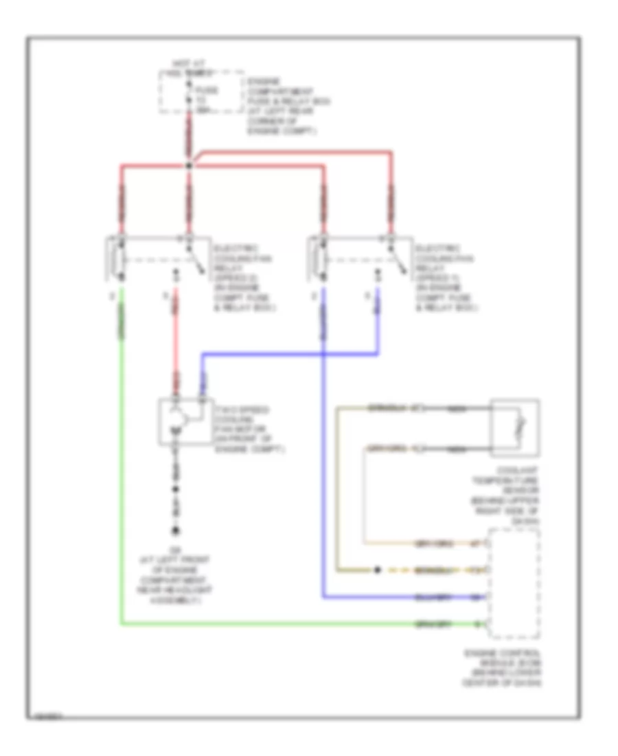
Cooling Fan Wiring Diagram for Volvo S40 2004
List of elements for Cooling Fan Wiring Diagram for Volvo S40 2004:
- Coolant temperature sensor (behind upper right side of dash)
- Electric cooling fan relay (speed 1) (in engine compt fuse & relay box)
- Electric cooling fan relay (speed 2) (in engine compt fuse & relay box)
- Engine compartment fuse & relay box (at left rear corner of engine compt)
- Engine control module (ecm) (behind lower center of dash)
- Fuse 30a
- G8 (at left front of engine compartment, near headlight assembly)
- Hot at all times
- Nca
- Red
- Two speed cooling fan motor (in front of engine compt)
CRUISE CONTROL
Cruise Control Wiring Diagram for Volvo S40 2004
List of elements for Cruise Control Wiring Diagram for Volvo S40 2004:
- A/t
- A13
- A18
- Acc
- Air conditioning system
- B15
- Brake lights/ unlocking gear selector contact (under left side of dash)
- Central electric module (behind left side of dash)
- Connector (under left side of dash, right of steering column)
- Cruise control brake pedal contact (on brake pedal bracket)
- Cruise control clutch pedal contact (on clutch pedal bracket)
- Cruise control ind
- Cruise control module (behind lower center of dash)
- Cruise control switch
- Cruise control vacuum pump (left rear corner of engine compt)
- D10
- Data link
- Dec
- Distribution rail (behind left center of dash)
- Driver information module
- Fuse 10a
- Fuse 15a
- G1 (at left rear of engine compt)
- G2 (at left rear of engine compt)
- Hot at all times
- Hot in on or start
- J14
- M/t
- Off
- Passenger compartment fuse & relay box (behind left side of dash)
- Pnk
- Red
- Res
- Speedometer
- Starter motor relay (in passenger compt, fuse & relay box)
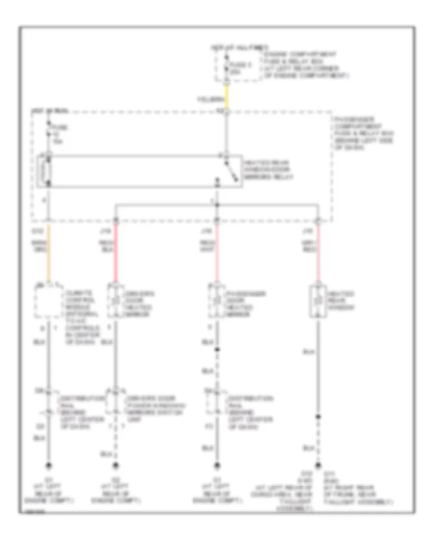
DEFOGGERS
Defoggers Wiring Diagram for Volvo S40 2004
List of elements for Defoggers Wiring Diagram for Volvo S40 2004:
- Climate control module (integral to a/c controls, in center of dash)
- Distribution rail (behind left center of dash)
- Driver's door heated mirror
- Driver's door power windows/ mirrors switch unit
- Engine compartment fuse & relay box (at left rear corner of engine compartment)
- Fuse 15a
- Fuse 5 25a
- G1 (at left rear of engine compt)
- G11 (s40) (at right rear of trunk, near taillight assembly)
- G12
- G12 (v40) (at left rear of cargo area, near taillight assembly)
- G2 (at left rear of engine compt)
- Heated rear window
- Heated rear window/door mirrors relay
- Hot at all times
- Hot in run
- J15
- J16
- J18
- Passenger compartment fuse & relay box (behind left side of dash)
- Passenger door heated mirror
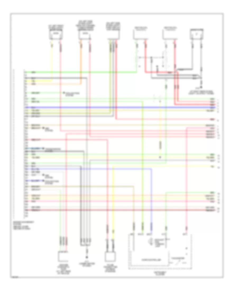
ENGINE PERFORMANCE
1.9L TURBO
1.9L Turbo, Engine Performance Wiring Diagram (1 of 3) for Volvo S40 2004
List of elements for 1.9L Turbo, Engine Performance Wiring Diagram (1 of 3) for Volvo S40 2004:
- (at left front of eng compt) evap valve
- (at right rear of eng compt, on strut tower)
- (on left side of eng compt) mass airflow (maf) sensor
- (on left side of eng compt, near air cleaner) turbocharger control valve
- + nca
- - nca
- 31/6
- 31/7 (under center of dash)
- A17
- Abs system
- B10
- B23
- Cooling fans system
- Engine management system (behind lower center of dash)
- Exhaust gas warning lamp
- Ignition coil (1 & 4 cyl)
- Ignition coil (2 & 3 cyl)
- Instrument cluster
- Leakage diagnostic pump (at left rear of vehicle)
- Micro-controller
- Nca
- Noise filter
- Pnk
- Pulse transmitter (on rear of engine)
- Red
- Tachometer
- Transmissions system
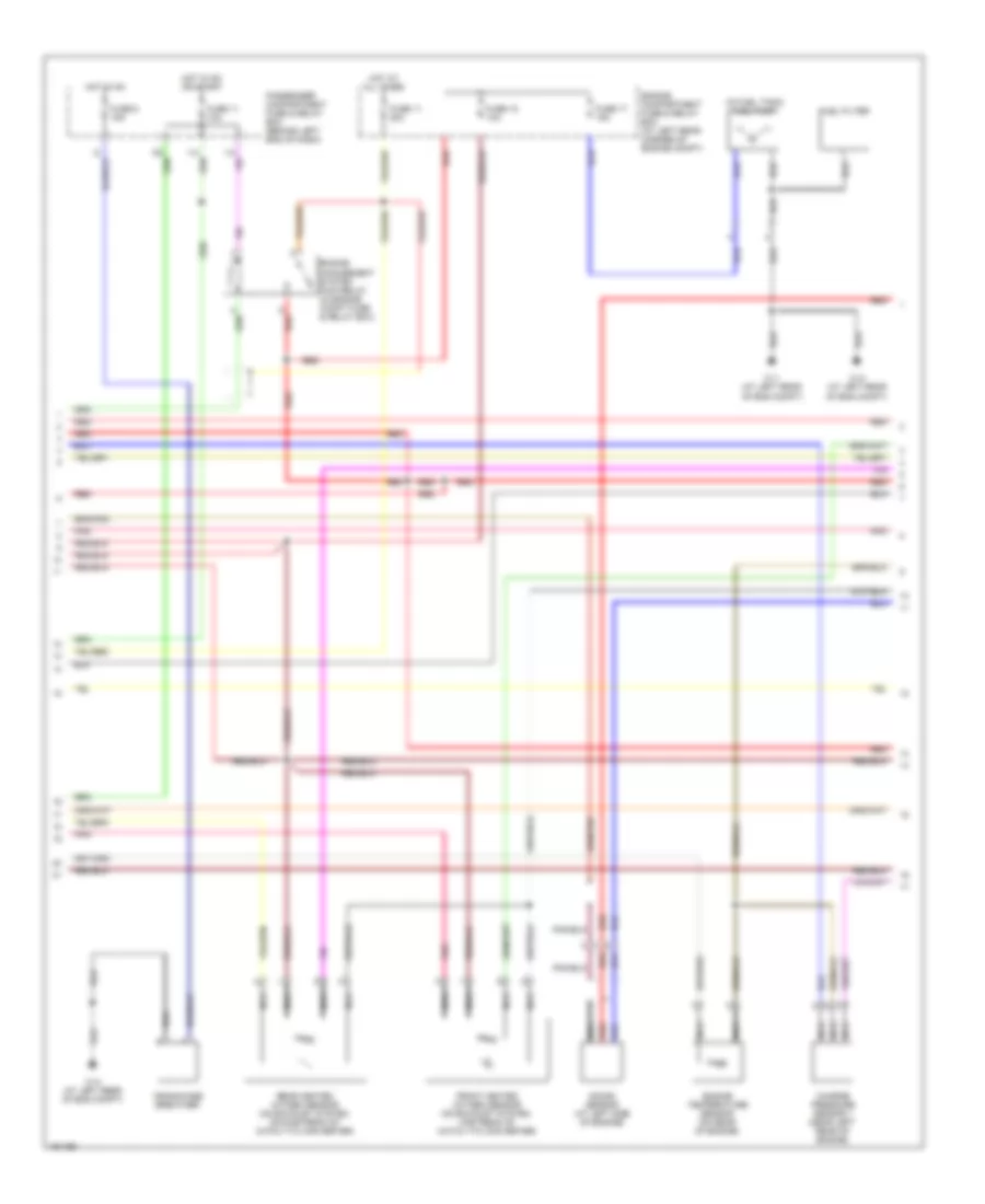
1.9L Turbo, Engine Performance Wiring Diagram (2 of 3) for Volvo S40 2004
List of elements for 1.9L Turbo, Engine Performance Wiring Diagram (2 of 3) for Volvo S40 2004:
- (in fuel tank) fuel pump
- 31/1 (at left rear of eng compt)
- 31/2 (at left rear of eng compt)
- 31/4 (at left rear of eng compt)
- Charge pressure sensor 1 (near left rear of engine)
- Crankcase breather
- Engine compartment fuse & relay box (at left rear corner of engine compt)
- Engine management system main relay (in engine compt fuse & relay box)
- Engine temperature sensor (on rear of engine)
- Front heated oxygen sensor (on exhaust system, upstream of catalytic converter)
- Fuel filter
- Fuse 11 10a
- Fuse 11 20a
- Fuse 17 15a
- Fuse 18 10a
- Fuse 6 15a
- Hot at all times
- Hot in on
- Hot in on or start
- I13
- I14
- Knock sensor (at left side of engine)
- Nca
- Passenger compartment fuse & relay box (behind left end of dash)
- Pnk
- Rear heated oxygen sensor (on exhaust system, downstream of catalytic converter)
- Red
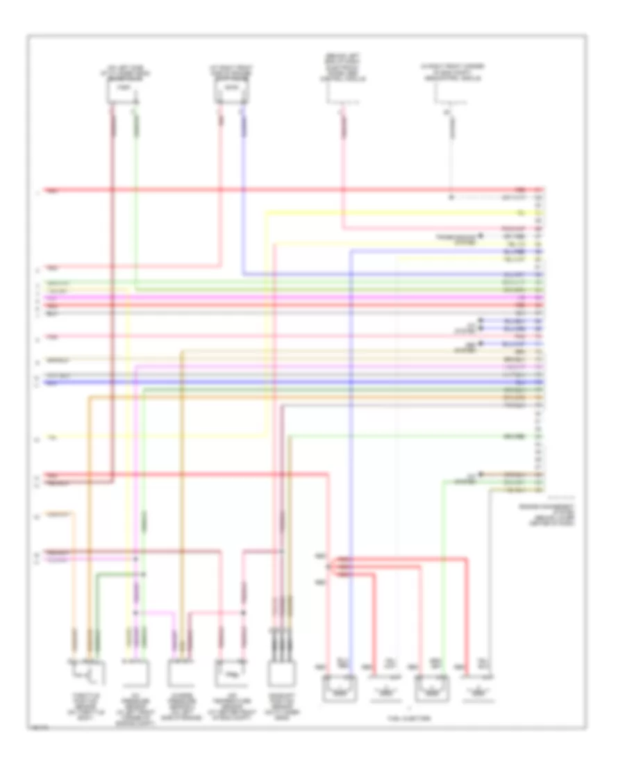
1.9L Turbo, Engine Performance Wiring Diagram (3 of 3) for Volvo S40 2004
List of elements for 1.9L Turbo, Engine Performance Wiring Diagram (3 of 3) for Volvo S40 2004:
- (at right front side of engine) cvvt valve
- (behind left end of dash) electronic immobilizer control module
- (in right front corner of eng compt) abs control module
- (on left side of cylinder head) idling valve
- A/c pressure sensor (in left front corner of engine compt)
- A/c system
- Abs system
- Air temperature sensor (at center front of eng compt)
- Camshaft position sensor (on cylinder head)
- Charge pressure sensor 2 (on left side of engine)
- Engine management system (behind lower center of dash)
- Fuel injectors
- Nca
- Pnk
- Red
- Throttle position sensor (on throttle body)
- Transmissions system
EXTERIOR LIGHTS
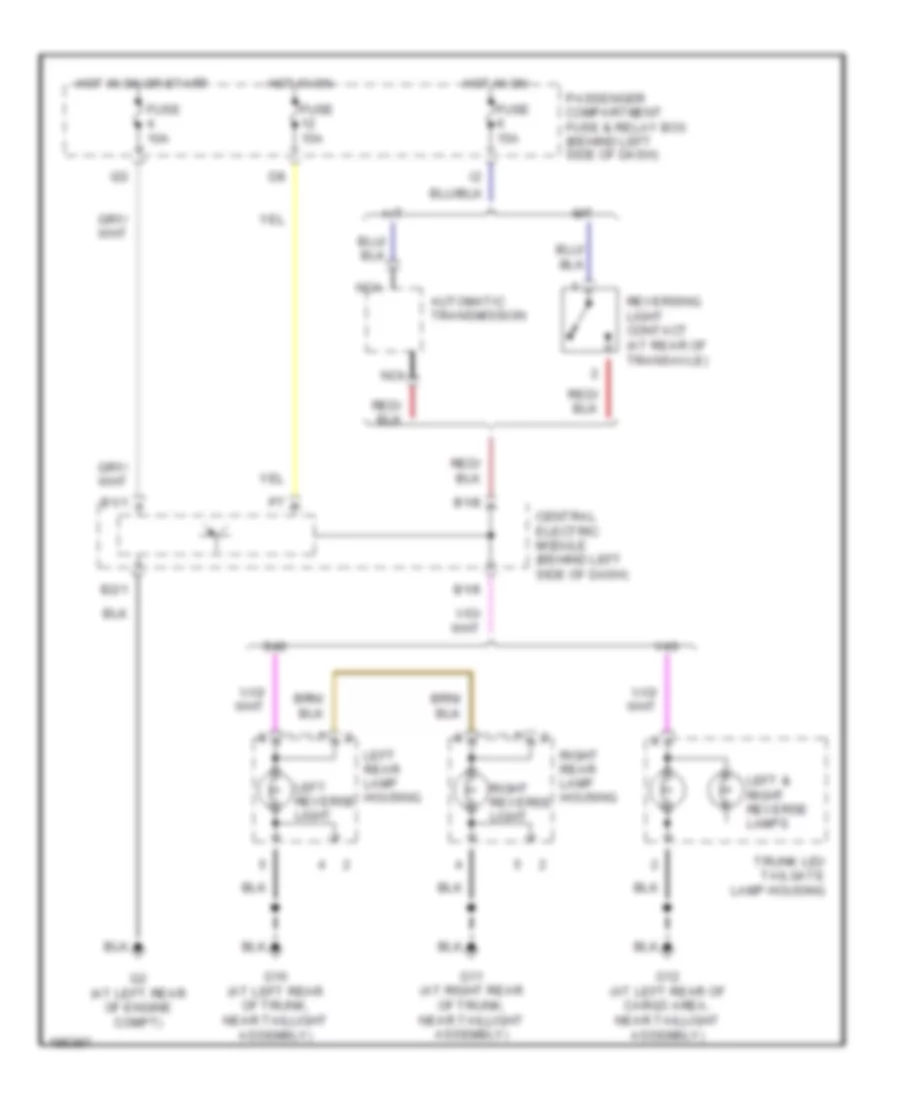
Back-up Lamps Wiring Diagram for Volvo S40 2004
List of elements for Back-up Lamps Wiring Diagram for Volvo S40 2004:
- A/t
- Automatic transmission
- B1/1
- B1/8
- B1/9
- B2/1
- Central electric module (behind left side of dash)
- Fuse 10a
- Fuse 15a
- G10 (at left rear of trunk, near taillight assembly)
- G11 (at right rear of trunk, near taillight assembly)
- G12 (at left rear of cargo area, near taillight assembly)
- G2 (at left rear of engine compt)
- Hot in on
- Hot in on or start
- I22
- Left & right reverse lamps
- Left rear lamp housing
- Left reverse light
- M/t
- Nca
- Passenger compartment fuse & relay box (behind left side of dash)
- Reversing light contact (at rear of transaxle)
- Right rear lamp housing
- Right reverse light
- S40
- Trunk lid/ tailgate lamp housing
- V40
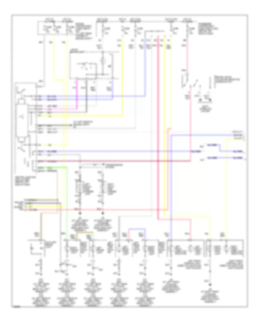
Exterior Lamps Wiring Diagram (1 of 2) for Volvo S40 2004
List of elements for Exterior Lamps Wiring Diagram (1 of 2) for Volvo S40 2004:
- (at left rear of engine compt) g2
- Auxiliary brake light
- B1/1
- B1/10
- B1/2
- B1/3
- B1/6
- B2/1
- B2/5
- Brake lights/ unlocking selector lever switch
- C12
- Central electric module (cem) (behind left side of dash)
- Engine compartment fuse & relay box (at left rear corner of engine compt)
- F11
- Fuse 10a
- Fuse 15a
- G10
- G10 (s40) (at left rear of trunk, near taillight assembly) g12 (v40) (at left rear of cargo area, near taillight assembly)
- G11 (s40) (at right rear of trunk, near taillight assembly) g13 (v40) (at right rear of cargo area, near taillight assembly)
- G6 g6
- G8 (at left front of engine compartment, near headlight assembly)
- G9 (at right front of engine compartment, near headlight assembly)
- Hot at all times
- Hot in acc or on
- Hot in on
- Hot in on or start
- I22
- Left brake light
- Left front direction indicator
- Left front park light
- Left front parking light/ direction indicator lamp housing
- Left front side marker lamp
- Left rear lamp hous- ing
- Left rear park light
- Lights switch unit
- Nca
- P16
- P17
- P18
- Passenger compartment fuse & relay box (behind left side of dash)
- Pnk
- Right brake light
- Right front direction indicator
- Right front park light
- Right front parking light/ direction indicator lamp housing
- Right front side marker lamp
- Right rear lamp hous- ing
- Right rear park light
- S40
- Shift interlock system
- Trailer tow connec- tor
- Transmissions system
- V40
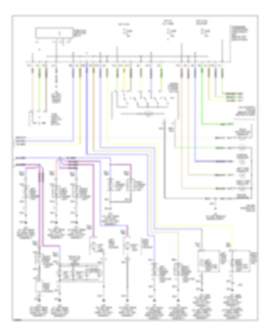
Exterior Lamps Wiring Diagram (2 of 2) for Volvo S40 2004
List of elements for Exterior Lamps Wiring Diagram (2 of 2) for Volvo S40 2004:
- (s40)
- (v40)
- A12
- A13
- A15
- A17
- A22
- A26
- B18
- Bulb malfunction indicator
- C12
- C14
- C15
- C16
- C17
- Direction indicator relay
- Driver information module
- E20
- Fuse 10a
- Fuse 15a
- G10 (at left rear of trunk, near taillight assembly)
- G10 (at left rear of trunk, near taillight assembly) g12 (at left rear of cargo area, near taillight assembly)
- G11 (at right rear of trunk, near taillight assembly)
- G11 (at right rear of trunk, near taillight assembly) g13 (at right rear of cargo area, near taillight assembly)
- G12 (at left rear of cargo area, near taillight assembly)
- G13 (at right rear of cargo area, near taillight assembly)
- G17
- G18
- G19
- G2 (at left rear of engine compt)
- G8 (at left front of engine compartment, near headlight assembly)
- G9 (at right front of engine compartment, near headlight assembly)
- Hazard warning flasher switch
- Hot at all times
- Hot in on
- Hot in on or start
- I19
- I20
- I21
- J14
- Left front fender direc- tion indicator lamp
- Left license plate lamp
- Left rear direction indicator lamp
- Left rear lamp hous -ing
- Left rear lamp housing
- Left rear side marker light
- Left tail light
- Left turn indicator
- License lights
- Nca
- Passenger compartment fuse & relay box (behind left side of dash)
- Pnk
- Right front fender direc- tion indicator lamp
- Right license plate lamp
- Right rear direction indicator lamp
- Right rear lamp hous -ing
- Right rear lamp housing
- Right rear side marker light
- Right tail light
- Right turn indicator
- S40
- Trailer indicator
- Trunk lid/ tailgate lamp housing
- Turn signal/ high-low beam switch
- Vgla control module (behind lower center of dash)
- Warning indicator
GROUND DISTRIBUTION
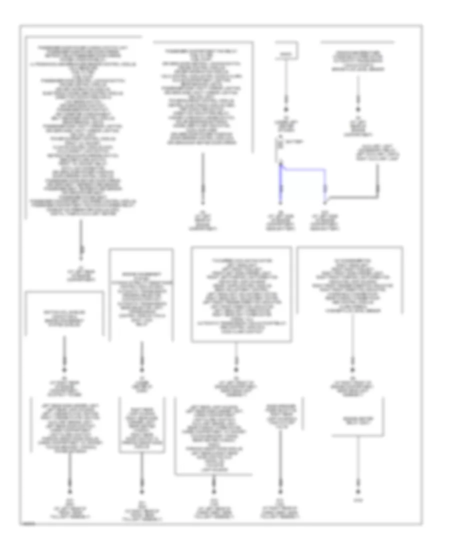
Ground Distribution Wiring Diagram for Volvo S40 2004
List of elements for Ground Distribution Wiring Diagram for Volvo S40 2004:
- Ac condenser fan, right headlight, front right foglight, right front side marker light, right front parking light/direction indicator lamp housing, right front fender direction indicator, right front direction indicator, windshield washer pump, rear window washer pump, abs control module, alarm siren & washer fluid level sensor
- Auxiliary light (accessory) relay, left auxiliary lamp & right auxiliary lamp
- Bass speaker passive/active, right rear lamp housing & tank cut-off valve
- Battery
- Crankcase breather, windshield wiper motor, automatic transmission vacuum pump & brake fluid level sensor
- Engine heater relay (230v)
- Engine management system, dynamic stability assistance control module (dsa), automatic transmission program selector, kick-down contact, automatic transmission gear selector light, transmission control module (tcm) & shift lock relay
- G1 (at left rear of engine compartment)
- G10 (s40) (at left rear of trunk, near taillight assembly)
- G102
- G11 (s40) (at right rear of trunk, near taillight assembly)
- G12 (v40) (at left rear of cargo area, near taillight assembly)
- G13 (v40) (at right rear of cargo area, near taillight assembly)
- G15 (at left side of engine compartment, near battery)
- G2 (at left rear of engine compartment)
- G3 (under left center of dash)
- G4 (at left rear of engine compartment)
- G5 (at left side of engine compartment, near battery)
- G6 (at right rear of engine compartment, on strut tower)
- G7 (under center of dash)
- G8 (at left front of engine compartment, near headlight assembly)
- G9 (at right front of engine compartment, near headlight assembly)
- Ignition coil shields, capacitor & engine management system shields
- Left rear lamp housing, left rear side marker light, cargo compartment light/alarm contact, auxiliary brake light, rear window wiper motor, cargo compartment 12v socket, towing bracket wiring, rear heated window, radio, parking assistance module, left rear & right rear door contacts & trunk lid/ tailgate lamp housing
- Left rear side marker light, left rear lamp housing, left license plate lighting, right license plate lighting, auxiliary brake light, left rear door contact, cargo compartment light/alarm contact, parking assistance module, cargo compartment 12v socket, towing bracket wiring & power antenna
- Passenger compartment fan relay, fuel filter, fuel pump, driver's door central locking switch, cruise control module, driver information module, vgla control module for locks & alarm, glove compartment lighting, rear reading lights, passenger side vanity mirror lighting, driver's side vanity mirror lighting, ceiling light, power sunroof control module, central electronic module (cem), trip computer switch, direction indicators relay, hazard warning flasher switch, solar sensor/electronic immobilizer alarm indication, audio amplifier, driver's door power windows/ door mirrors control module & driver's door heated door mirror
- Passenger door power window switch unit, passenger side power door mirror, retractable passenger door mirror, power windows relay, ultrasonicglass breakage sensor control module, vgla receiver, fuel filter, fuel pump, passenger door central locking switch, cruise control module, driver information module, electronic immobilizer control module, direction indicators/high & low beams switch, driver's door contact, passenger door contact, key-inserted warning/seat belt reminder control module, rear reading lights, passenger side vanity mirror lighting, driver's side vanity mirror lighting, ceiling light, power sunroof control module, front 12v socket, climate control module (ccm), child safety lock switch, retractable door mirrors switch, reduced alarm switch, front 12v socket relay, data link connector, driver's door power windows/ door mirrors control module, passenger door heated door mirror, driver's seat temperature sensor, passenger seat temperature sensor, driver's power seat, passenger power seat, passenger compartment fan speed control module, passenger compartment fan maximum speed relay, combustion preheater module (cpm), digital timer & auxiliary heater
- Radio
- Right rear lamp housing, right rear side marker light, rear heated window, right rear door contact & parking assistance module
- Two-speed cooling fan motor, left headlight, left front foglight, front left side marker light, front left parking light/direction indicator lamp housing, xenon lamps control module, beam adjustment control, left headlight adjustment motor, right headlight adjustment motor, left front fender direction indicator, left front direction indicator, left headlight wiper motor, right headlight wiper motor, horns 1 & 2, automatic transmission vacuum pump relay, abs control module & hood alarm contact
HEADLIGHTS
Headlights Wiring Diagram (1 of 2) for Volvo S40 2004
List of elements for Headlights Wiring Diagram (1 of 2) for Volvo S40 2004:
- A13
- B1/1
- B1/11
- B2/1
- B2/3
- B2/4
- Central electronic module (behind left side of dash)
- Driver information module
- Engine compartment fuse & relay box (at left rear corner of engine compt)
- F11
- F12
- F13
- F14
- F15
- F16
- Front foglight ind
- Fuse 10a
- Fuse 15a
- Fuse 20a
- G2 (at left rear of engine compt)
- G8 (at left front of engine compt, near headlight assembly)
- G9 (at right front of engine compt, near headlight assembly)
- High beam ind
- Hot at all times
- Hot in on
- Hot in on or start
- I22
- J14
- Left front foglight
- P10
- P12
- P13
- P16
- P17
- P18
- Passenger compartment fuse & relay box (behind left side of dash)
- Rear foglight ind
- Right front foglight
- S40
- Solid state
- V40
Headlights Wiring Diagram (2 of 2) for Volvo S40 2004
List of elements for Headlights Wiring Diagram (2 of 2) for Volvo S40 2004:
- Direction indicator high & low beam switch
- G1 (at left rear of engine compt)
- G10 (at left rear of trunk, near taillight assembly)
- G11 (at right rear of trunk, near taillight assembly)
- G12 (at left rear of cargo area, near taillight assembly)
- G8 (at left front of engine compt, near headlight assembly)
- G9 (at right front of engine compt, near headlight assembly)
- High beam
- Left head- light
- Left rear lamp housing
- Lights switch unit
- Low beam
- Rear fog- light
- Right head- light
- Right rear lamp housing
- Trunk lid tailgate lamp housing
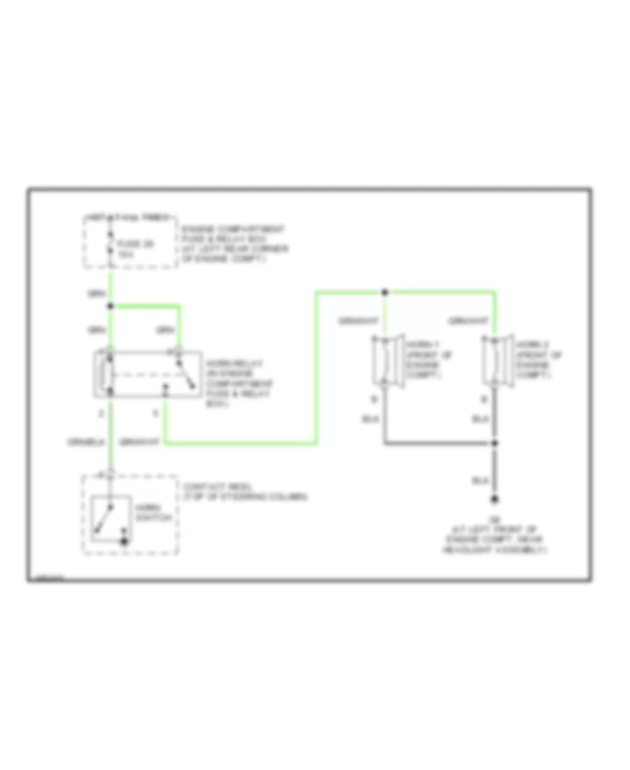
HORN
Horn Wiring Diagram for Volvo S40 2004
List of elements for Horn Wiring Diagram for Volvo S40 2004:
- Contact reel (top of steering column)
- Engine compartment fuse & relay box (at left rear corner of engine compt)
- Fuse 29 15a
- G8 (at left front of engine compt, near headlight assembly)
- Horn 1 (front of engine compt)
- Horn 2 (front of engine compt)
- Horn relay (in engine compartment fuse & relay box)
- Horn switch
- Hot at all times
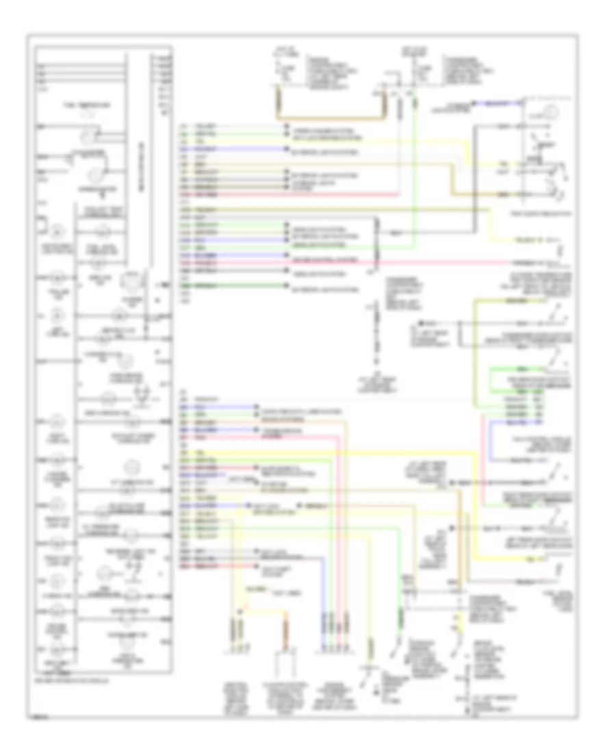
INSTRUMENT CLUSTER
Instrument Cluster Wiring Diagram for Volvo S40 2004
List of elements for Instrument Cluster Wiring Diagram for Volvo S40 2004:
- (at left rear of cargo area, near taillight assembly) g12
- (at left rear of engine compartment) g4
- (not used)
- A/t warning ind
- A10
- A11
- A12
- A13
- A14
- A15
- A16
- A17
- A18
- A19
- A20
- A21
- A22
- A23
- A24
- Abs warning ind
- Anti-lock brakes system
- Anti-theft system
- B10
- B11
- B12
- B13
- B14
- B15
- B16
- B17
- B18
- B19
- B20
- B21
- B22
- B23
- B24
- Brake fluid ind
- Brake fluid level sensor (on brake master cylinder reservoir)
- Bulb failure warning ind
- Central electric module (behind left side of dash)
- Charge ind
- Climate control module (ccm) (integral to a/c controls, in center of dash)
- Computer data lines system
- Coolant temp warning light
- Cruise control ind
- Cruise control system
- Door open ind
- Driver information module
- Driver's door contact (rear of driver door)
- E12
- Engine compartment fuse & relay box (at left rear corner of engine compt)
- Engine management system (behind lower center of dash)
- Exhaust gases warning ind
- Exterior lights system
- Front fog lamp ind
- Fuel level sensor (in fuel tank)
- Fuel level warning ind
- Fuel temp gauge
- Fuse a8 10a
- Fuse b11 10a
- G1 (at left rear of engine compartment)
- G10 (at left rear of trunk, near taillight assembly)
- G2 (at left rear of engine compartment)
- Hazard flashers ind
- Headlights system
- Hi beam ind
- Hot at all times
- Hot in on or start
- I10
- Illum
- Immobilizer ind
- Instrument lighting ind
- Interior lights system
- J14
- Left rear door contact (rear of left rear door)
- Left turn ind
- Micro-controller
- Oil pressure sensor (near oil filter)
- Oil pressure warning ind
- Osa & preheater ind
- Outside temperature trip computer sensor (on left front of vehicle, below headlight)
- Park brake warning ind
- Parking brake contact (at base of parking brake lever assembly)
- Passenger compartment fuse & relay box (behind left end of dash)
- Passenger compartment fuse & relay box (behind left side of dash)
- Passenger door contact (rear of front passenger door)
- Pnk
- Rear fog lamp ind
- Reset
- Reverse light ind (not used)
- Right rear door contact (rear of right rear door)
- Right turn ind
- Seat belt ind (not used)
- Service ind
- Sound systems
- Speedometer
- Srs warning ind
- Starting/ charging system
- Tachometer
- Trailer ind
- Transmissions system
- Trip computer switch
- Vgla control module (behind lower center of dash)
- Washer fluid ind
- Wiper/washer system
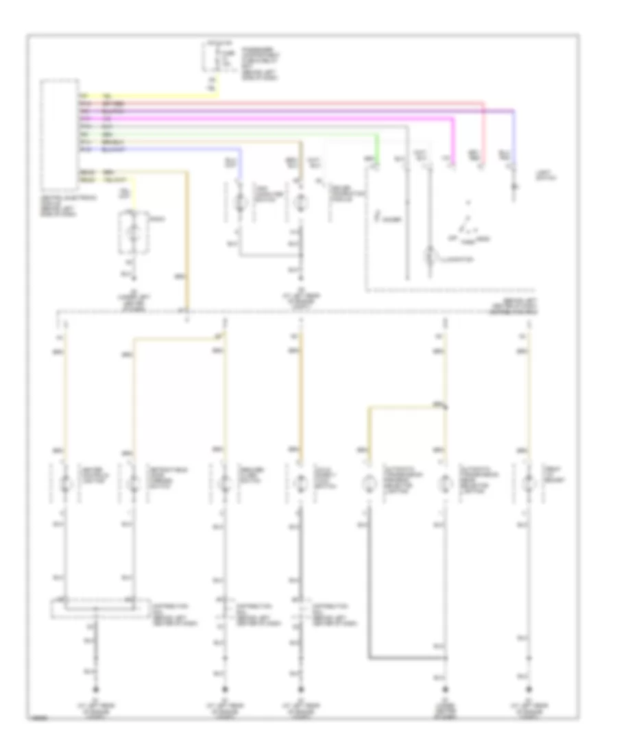
INTERIOR LIGHTS
Courtesy Lamps Wiring Diagram for Volvo S40 2004
List of elements for Courtesy Lamps Wiring Diagram for Volvo S40 2004:
- (at left rear of engine compt) g2
- (at left rear of trunk, near taillight assembly) g10 g12 (at left rear of cargo area, near taillight assembly)
- (at right rear of trunk, near taillight assembly) g11 g12 (at left rear of cargo area, near taillight assembly)
- (s40) (v40)
- A17
- A19
- A23
- A24
- A25
- B21
- C10
- Cargo compartment lighting (at left rear of cargo compartment)
- Ceiling light
- Courtesy lighting
- Distribution rail
- Door open indicator lamp
- Driver door contact (rear of driver door)
- Driver information module
- Driver's side vanity mirror lighting
- E10
- Engine compartment fuse & relay box (at left rear corner of engine compartment)
- Fuse 10a
- Fuse 15a
- Fuse 8 10a
- G1 (at left rear of engine compartment)
- G10 (s40) (at left rear of trunk, near taillight assembly) g12 (v40) (at left rear of cargo area, near taillight assembly)
- G11
- G13
- G14
- G2 (at left rear of engine compt)
- Glove compartment lighting
- Hot at all times
- Hot in on
- Left rear door contact (rear of left rear door)
- Lighting/ alarm, cargo compartment contact (at left rear of cargo compartment)
- Of engine compartment) g1
- Passenger compartment fuse & relay box (behind left side of dash)
- Passenger door contact (rear of front passenger door)
- Passenger side vanity mirror lighting
- Power antenna system
- Power sun roof switch
- Power top system
- Power tops system
- Rear reading lights
- Red
- Right rear door contact (rear of right rear door)
- S40
- Seat belt reminder indicator lamp
- Vgla door lock & alarm control module (behind lower center of dash)
- Warning system
Instrument Illumination Wiring Diagram for Volvo S40 2004
List of elements for Instrument Illumination Wiring Diagram for Volvo S40 2004:
- (behind left center of dash) distribution rail
- A13
- Automatic transmission gear selector lighting
- Automatic transmission program selector lighting
- B2/22
- B2/23
- Central electronic module (behind left side of dash)
- Child safety lock switch
- Dimmer
- Distribution rail (behind left center of dash)
- Driver information module
- Front 12v socket
- Fuse 10a
- G1 (at left rear of engine compt)
- G2 (at left rear of engine compt)
- G3 (under left center of dash)
- G7 (under center of dash)
- Head
- Heater controls lighting
- Hot in on
- Illumination
- Light switch
- Off
- P14
- P15
- P16
- P17
- P18
- Park
- Passenger compartment fuse & relay box (behind left side of dash)
- Radio
- Reduced alarm switch
- Retractable door mirrors switch
- Trip computer switch
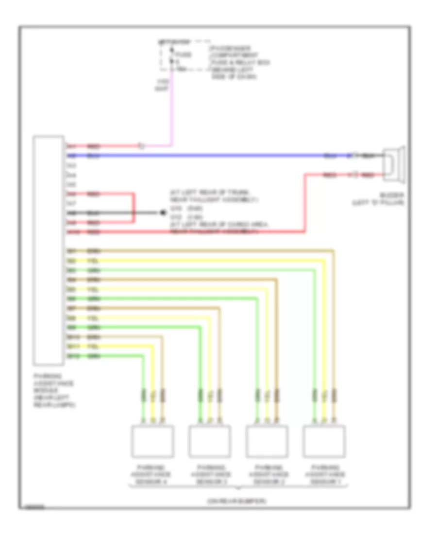
NAVIGATION
Navigation Wiring Diagram for Volvo S40 2004
List of elements for Navigation Wiring Diagram for Volvo S40 2004:
- (at left rear of trunk, near taillight assembly)
- (on rear bumper)
- (s40)
- (v40)
- A10
- B10
- B11
- B12
- Buzzer (left "d" pillar)
- Fuse 15a
- G10
- G12 (at left rear of cargo area, near taillight assembly)
- Hot in on
- Parking assistance module (near left rear lamps)
- Parking assistance sensor 1
- Parking assistance sensor 2
- Parking assistance sensor 3
- Parking assistance sensor 4
- Passenger compartment fuse & relay box (behind left side of dash)
- Red
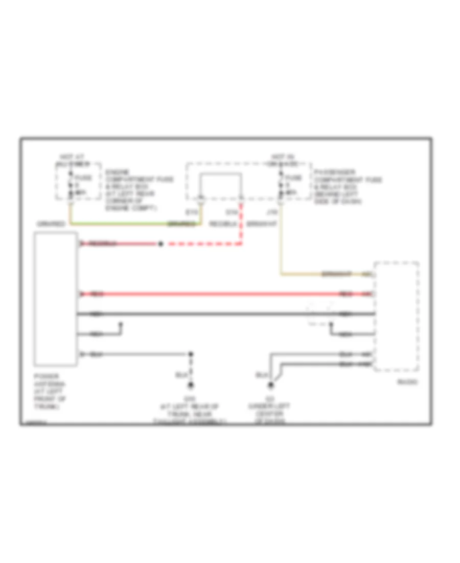
POWER ANTENNA
Power Antenna Wiring Diagram for Volvo S40 2004
List of elements for Power Antenna Wiring Diagram for Volvo S40 2004:
- A12
- E10
- Engine compartment fuse & relay box (at left rear corner of engine compt)
- Fuse 10a
- Fuse 15a
- G10 (at left rear of trunk, near taillight assembly)
- G14
- G3 (under left center of dash)
- Hot at all times
- Hot in on & acc
- J10
- Nca
- Passenger compartment fuse & relay box (behind left side of dash)
- Power antenna (at left front of trunk)
- Radio
- Red
POWER DISTRIBUTION
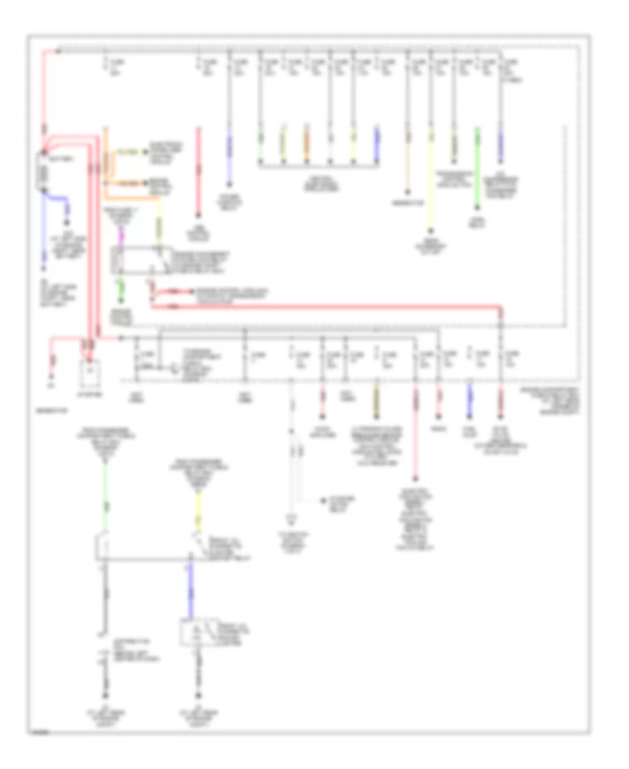
Power Distribution Wiring Diagram (1 of 3) for Volvo S40 2004
List of elements for Power Distribution Wiring Diagram (1 of 3) for Volvo S40 2004:
- (not used)
- (turbo)
- A/c compressor relay & a/c condenser fan relay
- Abs control module
- Audio amplifier
- Battery
- Central electronic module (cem)
- Distribution rail (behind left center of dash)
- Electric cooling fan speed 2 relay & electric cooling fan a/c relay
- Electric cooling fan speed 1 relay,
- Electronic immobilizer control module
- Engine compartment fuse & relay box (at left rear corner of engine compt)
- Engine control module
- Engine control module & automatic transmission vacuum pump
- Engine management system main relay (in engine compt fuse & relay box)
- Evap valve, heated oxygen sensors & idling valve
- From fuse 11 (diagram 3 of 3)
- From passenger compartment fuse & relay box (diagram 2 of 3)
- From passenger compartment fuse & relay box (diagram 3 of 3)
- Front 12v cigarette lighter socket relay
- Front 12v cigarette socket lighter
- Fuel pump
- Fuse
- Fuse 10a
- Fuse 120a
- Fuse 15a
- Fuse 20a
- Fuse 30a
- Fuse 40a
- Fuse 50a
- G1 (at left rear of engine compt)
- G15 (at left side of engine compt, near battery)
- G5 (at left side of engine compt, near battery)
- Generator
- Horn relay
- Power windows relay
- Radio
- Rear accessory outlet
- Red
- Starter
- Starter motor relay
- To engine compartment fuse & relay box (diagram 2 of 3)
- To ignition switch (diagram 3 of 3)
- Transmission control module (tcm)
- Ultrasonic glass breakage sensor control module, vgla control module for locks & alarm, vgla receiver
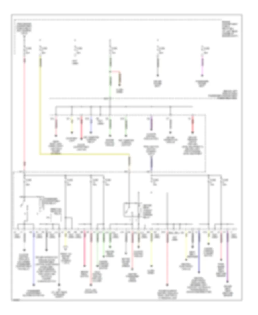
Power Distribution Wiring Diagram (2 of 3) for Volvo S40 2004
List of elements for Power Distribution Wiring Diagram (2 of 3) for Volvo S40 2004:
- (behind left side of dash) passenger compartment fuse & relay box
- (not
- (not used)
- Alarm siren
- Brake pedal switch
- C11
- C12
- C17
- Ceiling reading lights for high level equipment & ceiling light for standard level equipment
- Central electronic module
- Central electronic module (cem), reverse light contact, automatic transmission & crankcase breather
- Climate control module
- Climate control module & max speed passenger compartment fan relay
- Climate control module (ccm)
- Courtesy light
- Data link connector
- Direction indicator relay
- Driver information module
- Driver information module, glove compartment lighting, electronic immobilizer/ solar sensor alarm indication, trip computer switch & hazard warning switch
- Driver power seat
- Driver seat temp- erature sensor
- E10
- E14
- Engine compartment fuse & relay box (at left rear corner of engine compt)
- Engine control module
- From engine compartment fuse & relay box (diagram 1 of 3)
- From ignition switch (diagram 3 of 3)
- Front 12v socket relay (diagram 1 of 3)
- Fuse 10a
- Fuse 15a
- Fuse 20a
- Fuse 25a
- Fuse 30a
- Fuse 40a
- G11
- G13
- G14
- G15
- G16
- G2 (at left rear of engine compt)
- G6 pnk
- Glove compartment lighting
- Hazard warning flasher switch
- Heated driver door mirror
- Heated passenger door mirror
- Heated rear window
- Heated rear window & door mirrors relay
- I17
- I18
- J13
- J14
- J15
- J18
- Key inserted warning contact
- Key inserted warning relay
- Not used
- Pass- enger seat temp- erature sensor
- Passenger compartment blower motor fan
- Passenger compartment fan relay
- Passenger power seat
- Power sunroof control module & roof lamp for hl w/ reading lamp
- Rear roof lamp, cargo compt lighting & power antenna
- Red
- Seat belt reminder
- Used)
- Vgla control module for lock & alarm
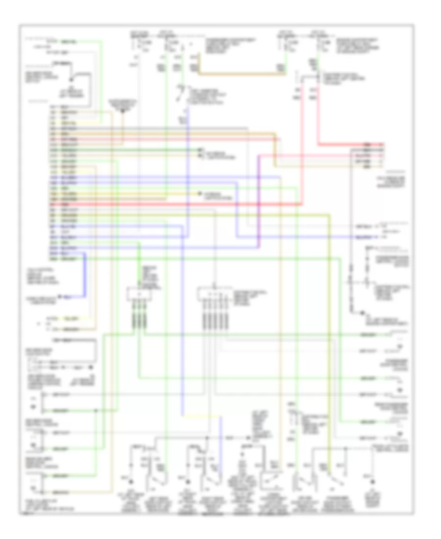
Power Distribution Wiring Diagram (3 of 3) for Volvo S40 2004
List of elements for Power Distribution Wiring Diagram (3 of 3) for Volvo S40 2004:
- (behind left side of dash) passenger compartment fuse & relay box
- (not used)
- +30
- +50
- Abs control module
- Acc
- Bass speaker
- Brake pedal switch
- C18
- Cargo compartment 12v socket
- Central electronic module
- Cruise control switches & cruise control module
- Driver information module
- E11
- E13
- E15
- Electronic immobilizer control module
- From fuse 14 (diagram 1 of 3)
- Fuel injection/ combustion relay & fuel pump relay
- Fuse 10a
- Fuse 15a
- Fuse 20a
- I12
- I13
- I14
- I15
- I16
- I22
- Ig1
- Ig2
- Ignition switch
- J10
- J11
- J12
- Lock
- Not used
- Off
- Radio & audio amplifier
- Rear windshield/ wiper switch
- Red
- Right headlamp wiper motor & left headlamp wiper motor
- Srs control module
- Start
- Starter motor relay
- To engine management system main relay (diagram 1 of 3)
- To front 12v cigarette socket relay lighter relay (diagram 1 of 3)
- To passenger compartment fuse & relay box (diagram 2 of 3)
- Transmission control module, engine control module & dynamic stability assistance control module
- Vgla control module for lock & alarm
- Vgla control module for locks & alarm, passenger power seat, power windows relay, driver door adjustable mirror, adjustable door mirror switch & passenger door adjustable mirror
- Windshield/ wiper motor
- Windshield/wiper switch, rear window & washer/ wiper switch
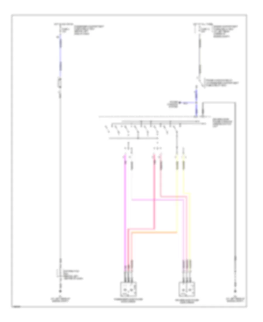
POWER DOOR LOCKS
Power Door Locks Wiring Diagram for Volvo S40 2004
List of elements for Power Door Locks Wiring Diagram for Volvo S40 2004:
- (at left rear of cargo area, near taillight assembly) g12
- (behind left center of dash)
- (v40: at left rear of cargo area, near taillight assembly)
- A10
- A12
- A13
- A15
- A16
- A18
- A19
- A20
- A23
- A24
- A26
- B10
- B12
- B16
- B19
- B22
- C10
- Cargo compartment lighting/ alarm contact (at left rear of cargo compt)
- Center of dash)
- Computer data lines system
- Distrib- ution rail
- Distribution rail (behind left center of dash)
- Driver door contact (rear of driver door)
- Driver's door central locking
- Driver's door central locking switch
- Driver's door lock switch
- Driver's door power windows/ mirrors control module
- E10
- Engine compartment fuse & relay box (at left rear corner of engine compt)
- Exterior lights system
- F10
- Fuel filler flap lock motor (at left rear of vehicle)
- Fuse 10a
- Fuse 20a
- G1 (at left rear of engine compartment)
- G1 (at left rear of engine compt)
- G10 (at left rear of trunk, near taillight assembly)
- G10 (s40)
- G11 (at right rear of trunk, near taillight assembly)
- G12 (v40) (s40: at left rear of trunk, near taillight assembly)
- G15
- G2 (at rear of left fender)
- Hot at all times
- Hot in on or start
- Interior lights system
- Key inserted warning contact (integral to ignition switch)
- Left rear door contact (rear of left rear door)
- Passenger compartment fuse & relay box (behind left side dash)
- Passenger door central locking
- Passenger door central locking switch
- Passenger door contact (rear of front passenger door)
- Rear driver's side door central locking
- Rear passenger door central locking
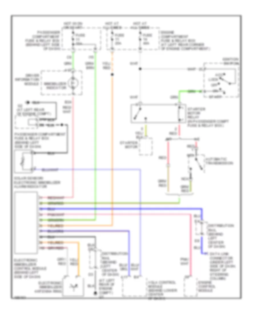
- Red
- Right rear door contact (rear of right rear door)
- S40
- Trunk lid/tailgate central locking
- V40
- Vgla control module (behind lower
- Vgla receiver (in rear of engine compt)
POWER MIRRORS
Power Mirrors Wiring Diagram for Volvo S40 2004
List of elements for Power Mirrors Wiring Diagram for Volvo S40 2004:
- Distribution rail (behind left center of dash)
- Driver's door power windows/ mirrors switch unit
- Driver's side power door mirror
- Engine compartment fuse & relay box (at left rear corner of engine compt)
- F11
- Fuse 12 30a
- Fuse 3 10a
- G1 (at left rear of engine compt)
- G2 (at left rear of engine compt)
- Hot at all times
- Hot in acc or on
- Nca
- Passenger compartment fuse & relay box (behind left side of dash)
- Passenger's side power door mirror
- Pnk
- Power windows relay (in passenger compartment fuse & relay box)
- Power windows system
POWER SEATS
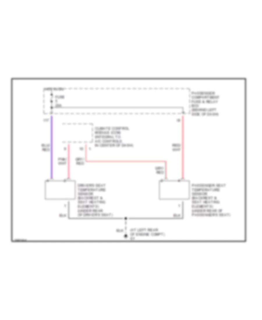
Heated Seats Wiring Diagram for Volvo S40 2004
List of elements for Heated Seats Wiring Diagram for Volvo S40 2004:
- (at left rear of engine compt) g1
- Climate control module (ccm) (integral to a/c controls, in center of dash)
- Driver's seat temperature sensor (backrest & seat heating elements) (under rear of driver's seat)
- Fuse 20a
- Hot in on
- I17
- Passenger compartment fuse & relay box (behind left side of dash)
- Passenger seat temperature sensor (backrest & seat heating elements) (under rear of passenger's seat)
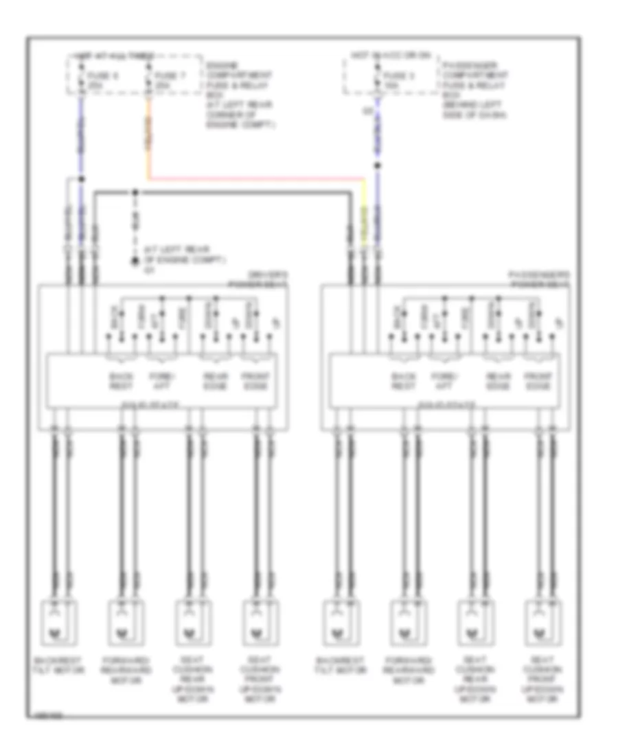
Power Seats Wiring Diagram for Volvo S40 2004
List of elements for Power Seats Wiring Diagram for Volvo S40 2004:
- (at left rear of engine compt) g1
- Aft
- Back
- Back rest
- Backrest tilt motor
- Down
- Driver's power seat
- Engine compartment fuse & relay box (at left rear corner of engine compt)
- Fore
- Fore/ aft
- Forw
- Forward/ rearward motor
- Front edge
- Fuse 3 10a
- Fuse 6 25a
- Fuse 7 25a
- Hot at all times
- Hot in acc or on
- Nca
- Passenger compartment fuse & relay box (behind left side of dash)
- Passenger's power seat
- Rear edge
- Seat cushion front up/down motor
- Seat cushion rear up/down motor
- Solid state
POWER TOP/SUNROOF
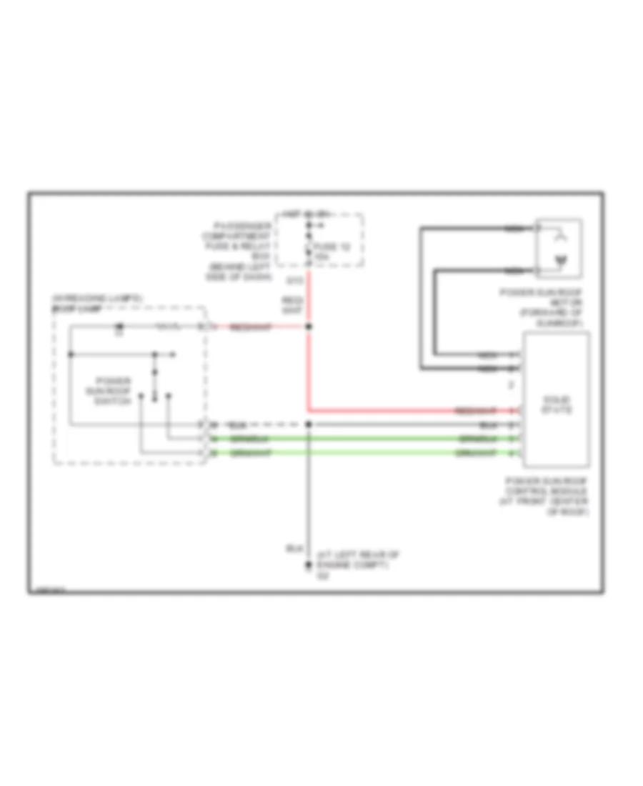
Sunroof Wiring Diagram for Volvo S40 2004
List of elements for Sunroof Wiring Diagram for Volvo S40 2004:
- (at left rear of engine compt) g2
- (w/reading lamps) roof lamp
- Fuse 12 15a
- G13
- Hot in on
- Nca
- Passenger compartment fuse & relay box (behind left side of dash)
- Power sun roof control module (at front center of roof)
- Power sun roof motor (forward of sunroof)
- Power sun roof switch
- Solid state
POWER WINDOWS
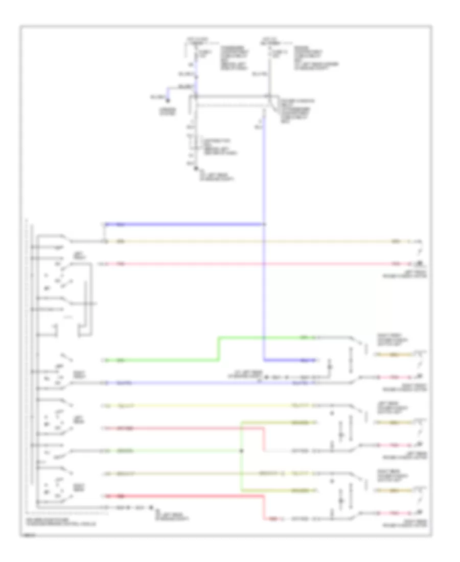
Power Windows Wiring Diagram for Volvo S40 2004
List of elements for Power Windows Wiring Diagram for Volvo S40 2004:
- (at left rear of engine compt) g1
- Distribution rail (behind left center of dash)
- Driver's door power windows/mirrors control module
- Engine compartment fuse & relay box (at left rear corner of engine compt)
- F11
- Fuse 12 30a
- Fuse 3 10a
- G1 (at left rear of engine compt)
- G2 (at left rear of engine compt)
- Hot at all times
- Hot in acc or on
- Left front
- Left front power window motor
- Left rear
- Left rear power window motor
- Left rear power window switch unit
- Mirrors system
- Off
- Passenger compartment fuse & relay box (behind left side of dash)
- Pnk
- Power windows relay (in passenger compartment fuse & relay box)
- Red
- Right front
- Right front power window motor
- Right front power window switch unit
- Right rear
- Right rear power window motor
- Right rear power window switch unit
RADIO
Radio Wiring Diagram, with Amplifier for Volvo S40 2004
List of elements for Radio Wiring Diagram, with Amplifier for Volvo S40 2004:
- (at left rear of cargo area, near taillight assembly)
- (not used)
- (s40)
- (v40)
- 10 cd changer
- 6 cd changer
- A10
- A11
- A12
- Amplifier (v40) (on rear of roof)
- Antenna
- Audio amplifier
- B1-8
- B10
- B11
- B12
- B2-23
- Bass speaker (v40)
- Cd changer (if equipped)
- Central electric module (cem) (behind left side of dash)
- Driver information module
- Driver's side dash- board speaker
- E10 nca
- Engine compartment fuse & relay box (at left rear corner of engine compt)
- Fuse 10a
- Fuse 15a
- Fuse 20a
- G10 (at left rear of trunk, near taillight assembly)
- G12
- G12 (at left rear of cargo area, near taillight assembly)
- G2 (at left rear of engine compt)
- G3 (under left center of dash)
- Gps antenna
- Hot at all times
- Hot in acc or on
- Left front door speaker
- Left rear speaker
- Nca
- Passenger compartment fuse & relay box (behind left side of dash)
- Passenger side dash- board speaker
- Power antenna (s40) (at left front of trunk)
- Radio
- Red
- Right front door speaker
- Right rear speaker
- S40
- V40
Radio Wiring Diagram, without Amplifier for Volvo S40 2004
List of elements for Radio Wiring Diagram, without Amplifier for Volvo S40 2004:
- (not used)
- (s40)
- (v40)
- 10 cd changer
- 6 cd changer
- A10
- A11
- A12
- Amplifier (v40) (on rear of roof)
- Antenna
- B1-8
- B10
- B11
- B12
- B2-23
- Bass speaker (v40)
- Cd changer (if equipped)
- Central electric module (cem) (behind left side of dash)
- Driver information module
- Driver's side dashboard speaker
- E10 nca
- Engine compartment fuse & relay box (at left rear corner of engine compt)
- Fuse 10a
- Fuse 15a
- G10 (at left rear of trunk, near taillight assembly)
- G12 (at left rear of cargo area, near taillight assembly)
- G13 (at right rear of cargo area, near taillight assembly)
- G3 (under left center of dash)
- Gps antenna
- Hot at all times
- Hot in acc or on
- Left front door speaker
- Left rear speaker
- Nca
- Passenger compartment fuse & relay box (behind left side of dash)
- Passenger side dashboard speaker
- Power antenna (s40) (at left front of trunk)
- Radio
- Red
- Right front door speaker
- Right rear speaker
- S40
- V40
SHIFT INTERLOCK
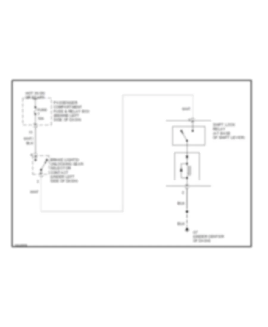
Shift Interlock Wiring Diagram for Volvo S40 2004
List of elements for Shift Interlock Wiring Diagram for Volvo S40 2004:
- Brake lights/ unlocking gear selector contact (under left side of dash)
- Fuse 10a
- G7 (under center of dash)
- Hot in on or start
- Passenger compartment fuse & relay box (behind left side of dash)
- Shift lock relay (at base of shift lever)
STARTING/CHARGING
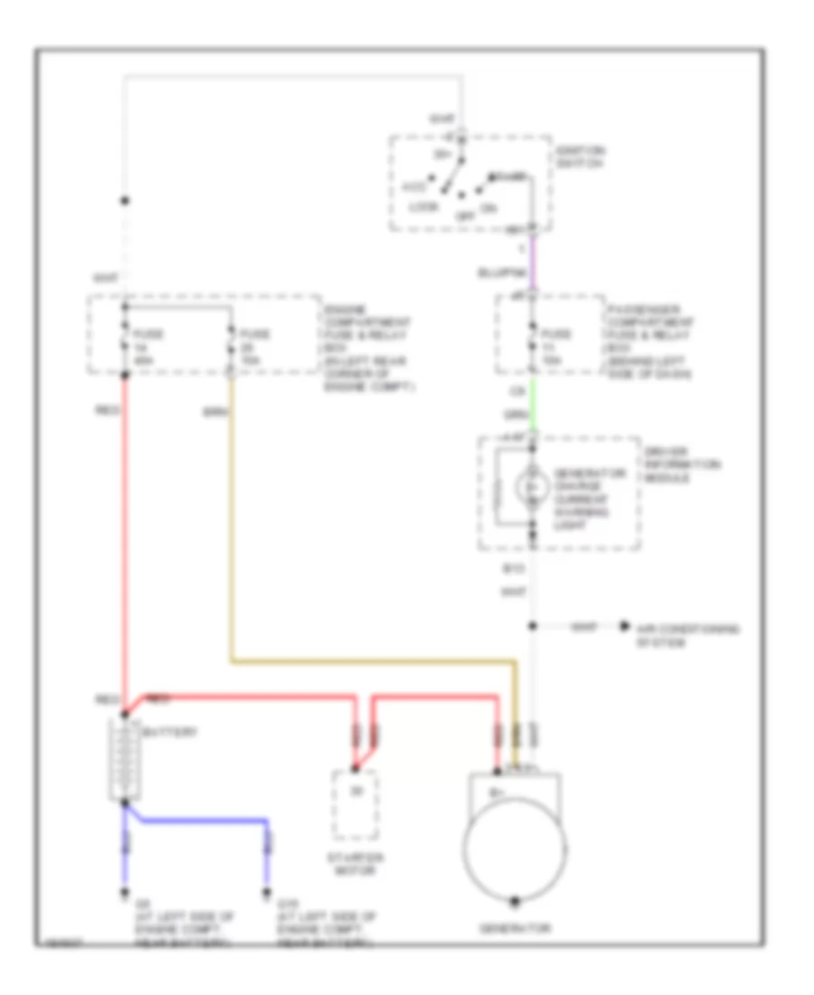
Charging Wiring Diagram for Volvo S40 2004
List of elements for Charging Wiring Diagram for Volvo S40 2004:
- 30+
- A17
- Acc
- Air conditioning system
- B13
- Battery
- Driver information module
- Engine compartment fuse & relay box (in left rear corner of engine compt)
- Fuse 10a
- Fuse 40a
- G15 (at left side of engine compt, near battery)
- G5 (at left side of engine compt, near battery)
- Generator
- Generator charge current warning light
- Ig1
- Ignition switch
- Lock
- Off
- Passenger compartment fuse & relay box (behind left side of dash)
- Red
- Start
- Starter motor
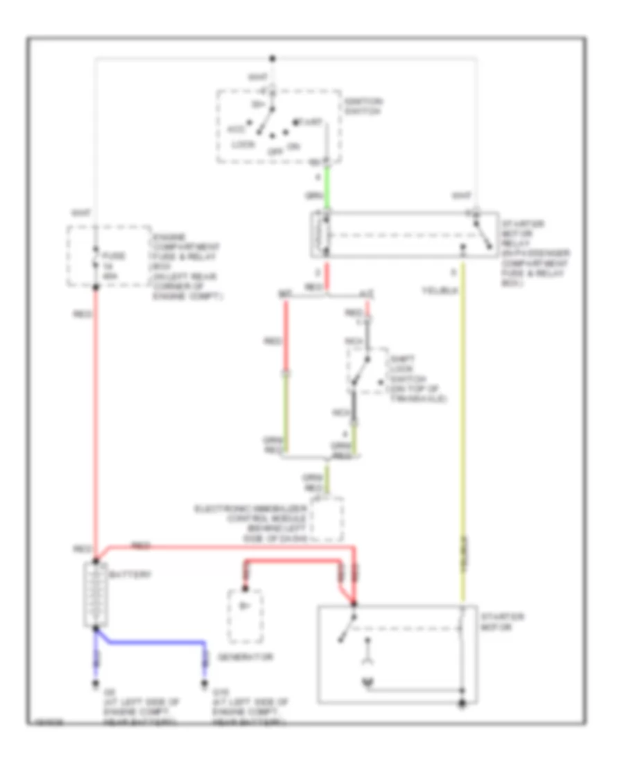
Starting Wiring Diagram for Volvo S40 2004
List of elements for Starting Wiring Diagram for Volvo S40 2004:
- 30+
- A/t
- Acc
- Battery
- Electronic immobilizer control module (behind left side of dash)
- Engine compartment fuse & relay box (in left rear corner of engine compt)
- Fuse 40a
- G15 (at left side of engine compt, near battery)
- G5 (at left side of engine compt, near battery)
- Generator
- Ignition switch
- Lock
- M/t
- Nca
- Off
- Red
- Shift lock switch (on top of transaxle)
- Start
- Starter motor
- Starter motor relay (in passenger compartment fuse & relay box)
SUPPLEMENTAL RESTRAINTS
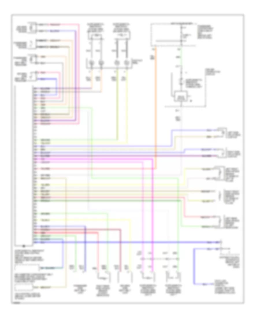
Supplemental Restraints Wiring Diagram for Volvo S40 2004
List of elements for Supplemental Restraints Wiring Diagram for Volvo S40 2004:
- A10
- A17
- B11
- Contact reel
- Data link connector (partial) (under left side of dash, right of steering column)
- Distribution rail (diagnostic) (behind left center of dash)
- Driver information module
- Driver's side seat belt lock
- Driver's side seat belt tensioner
- Driver's side side air bag
- Fuse 11 10a
- Hot in on or start
- I16
- Key-inserted warning/seat belt reminder control module (in passenger compartment fuse & relay box)
- Left front side air bag sensor (at base of left "b" pillar)
- Left rear side air bag sensor (in left rear door)
- Left side inflatable curtain
- Nca
- Passenger compartment fuse & relay box (behind left end of dash)
- Passenger side seat belt lock
- Passenger side seat belt tensioner
- Passenger side side air bag
- Pnk
- Red
- Right front side air bag sensor (at base of right "b" pillar)
- Right rear side air bag sensor (in right rear door)
- Right side inflatable curtain
- Solid state
- Vgla control module (behind lower center of dash)
TRANSMISSION
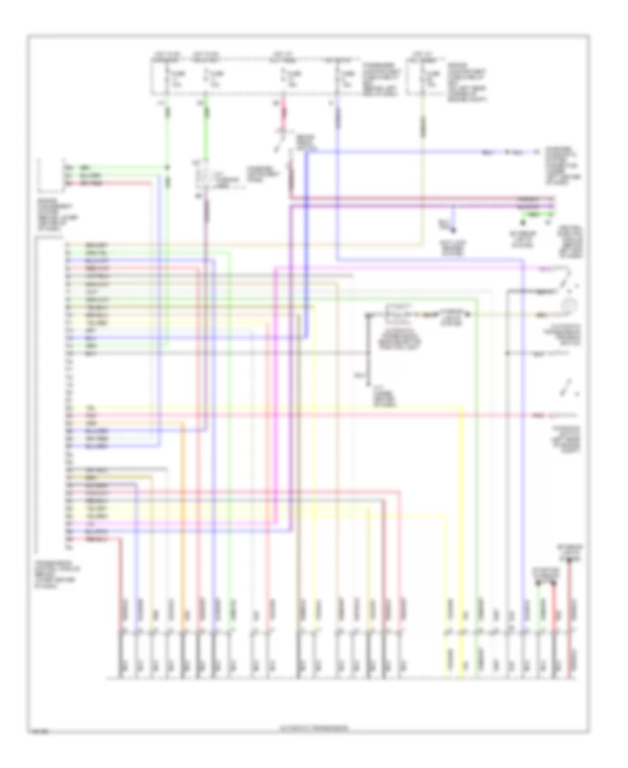
Transmission Wiring Diagram for Volvo S40 2004
List of elements for Transmission Wiring Diagram for Volvo S40 2004:
- 31/7 (under center of dash)
- A/t warning lamp
- A17
- Anti-lock brakes system
- Automatic transmission
- Automatic transmission gear selector position light
- Automatic transmission program switch
- Brake pedal switch
- Central electric module (behind left end of dash)
- Combined instrument panel
- Engine compartment fuse & relay box (on left rear corner of engine compt)
- Engine management system (behind lower center of of dash)
- Exterior lights system
- Fuse 10a
- Fuse 15a
- Hot at all times
- Hot in on
- Hot in on or start
- I14
- Interior lights system
- Kickdown switch (left rear of engine compt)
- Nca
- On-board diagnostic system connector (under left center of dash)
- Passenger compartment fuse & relay box (behind left end of dash)
- Pnk
- Red
- Starting/ charging system
- Transmission control module (behind lower center of dash)
WARNING SYSTEMS
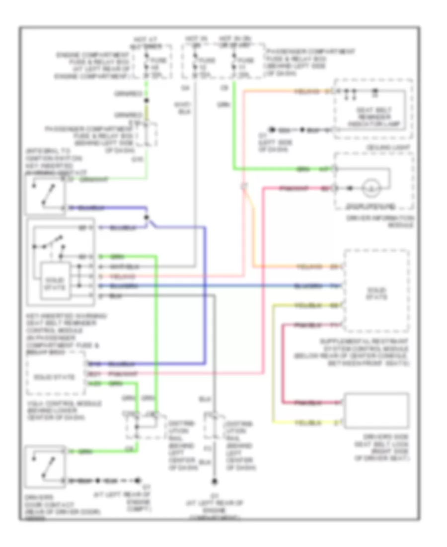
Warning Systems Wiring Diagram for Volvo S40 2004
List of elements for Warning Systems Wiring Diagram for Volvo S40 2004:
- (integral to ignition switch) key inserted warning contact
- A23
- Ai7
- B10
- B21
- C10
- Ceiling light
- Distrib- ution rail (behind left center of dash)
- Door open ind
- Driver information module
- Driver's door contact (rear of driver door)
- Driver's side seat belt lock (right side of driver seat)
- Engine compartment fuse & relay box (at left rear of engine compartment)
- Fuse 10a
- Fuse 15a
- Fuse a8 10a
- G1 (at left rear of engine compartment)
- G1 (at left rear of engine compt)
- G1 (left side of dash)
- G15
- Hot at all times
- Hot in on
- Hot in on or start
- Key-inserted warning/ seat belt reminder control module (in passenger compartment fuse & relay box)
- Passenger compartment fuse & relay box (behind left side of dash)
- Seat belt reminder indicator lamp
- Solid state
- Vgla control module (behind lower center of dash)
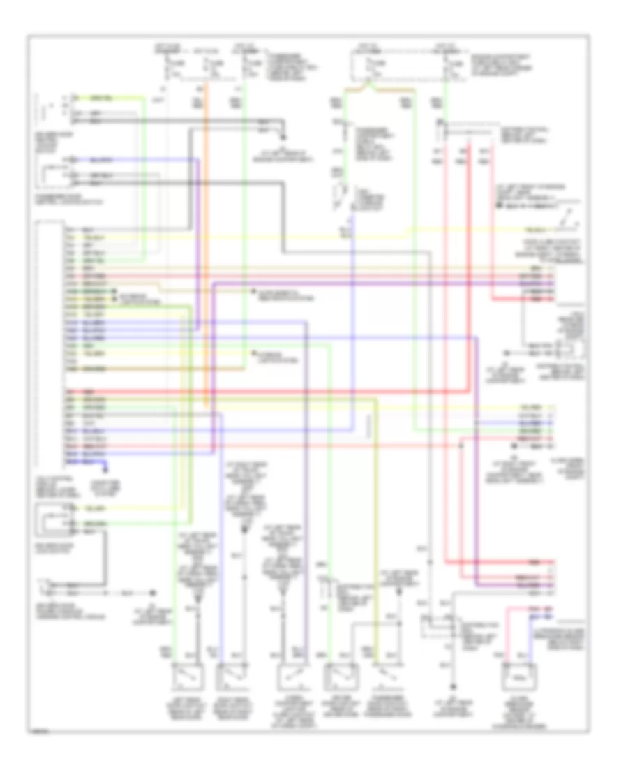
WIPER/WASHER
Wiper/Washer Wiring Diagram for Volvo S40 2004
List of elements for Wiper/Washer Wiring Diagram for Volvo S40 2004:
- (behind left side of dash) passenger compartment fuse & relay box
- A17
- Abs control module (in right front corner of engine compt)
- Air conditioning system
- B15
- B16
- Central electric module (behind left side of dash)
- Climate control module (ccm) (integral to a/c controls, in center of dash)
- Driver information module
- Dynamic stability assistance control module (behind right side of dash)
- E13
- E15
- E16
- E17
- E19
- Fuse 10a
- Fuse 20a
- G12 (at left rear of cargo area, near taillight assembly)
- G2 (at left rear of engine compt)
- G4 (at left rear of engine compartment)
- G8 (at left front of engine compartment, near headlight assembly)
- G9 (at right front of engine compartment, near headlight assembly)
- G9 (at right front of engine compt, near headlight assembly)
- Hot in on or acc
- Hot in on or start
- I12
- Left headlight wiper motor (under respective headlight assemblies)
- Passenger compartment fuse & relay box (behind left side of dash)
- Rear window washer pump (v40) (at right front corner of engine compt, on washer fluid reservoir)
- Rear window wiper motor (v40) (on liftgate)
- Rear window wiper/washer switch
- Red
- Right headlight wiper motor (under respective headlight assemblies)
- Solid state
- Speedo- meter
- Washer fluid indicator light
- Washer fluid level sensor (on washer fluid reservoir)
- Windshield rear window wiper switch
- Windshield washer pump (at right front corner of engine compt, on washer fluid reservoir)
- Windshield wiper motor (at right rear of engine compt)
- Windshield wiper switch
- Windshield wiper/washer switch

 Čeština
 Dansk
Dansk Deutsch
 Ελληνικά
 English
 English
 Español
 Suomi
Suomi Français
 Français
 עברית
עברית Hrvatski
 Magyar
 Italiano
 日本語
日本語 한국어
한국어 Nederlands
 Polski
 Português
 Português
 Русский
 Slovenčina
 Slovenščina
 Svenska
 Türkçe
 中文 (中国)