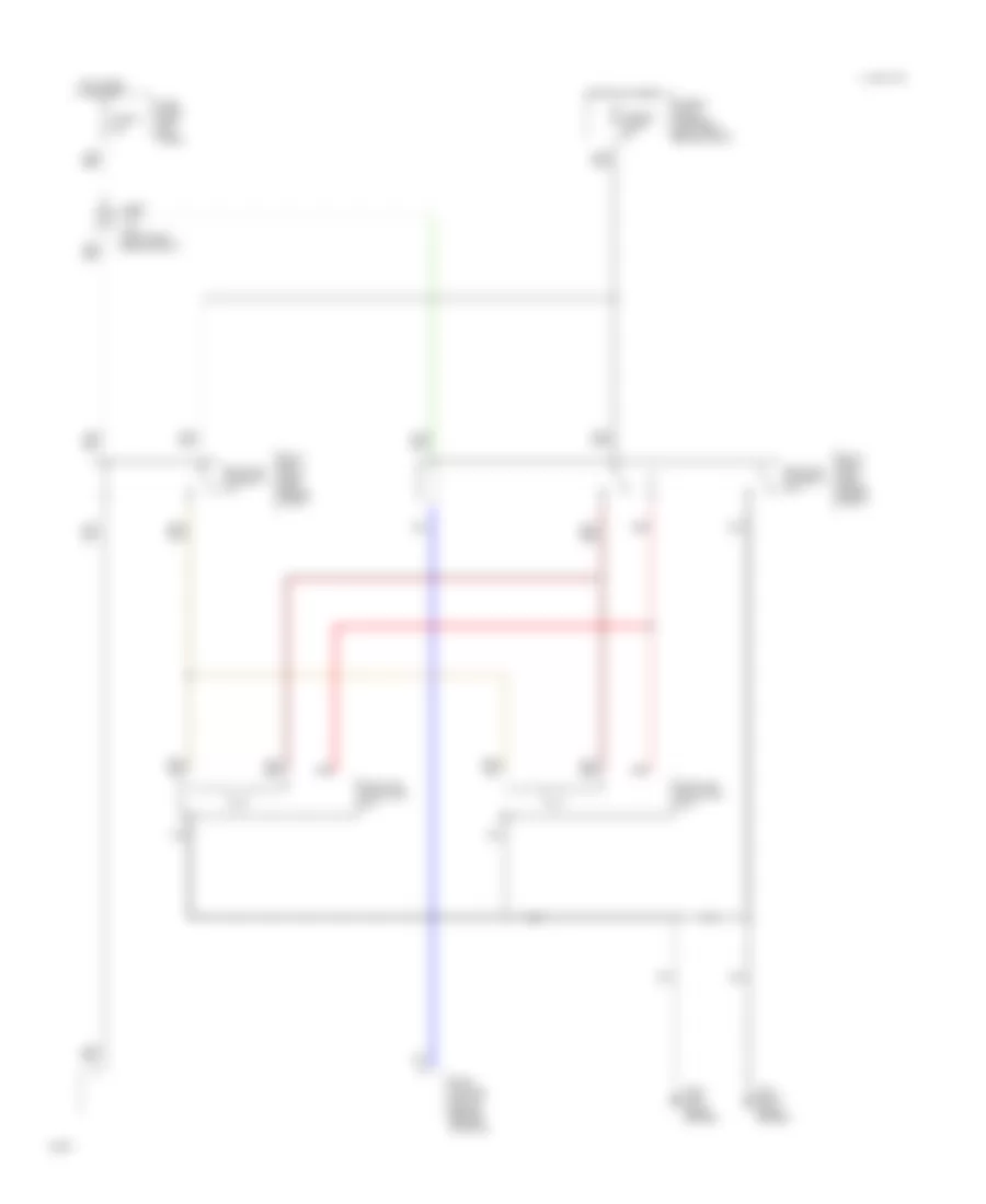
COOLING FAN
Cooling Fan Wiring Diagram, A/T for Infiniti G20 1994
 https://portal-diagnostov.com/license.html
Automotive Electricians Portal FZCO
Automotive Electricians Portal FZCO
https://portal-diagnostov.com/license.html
https://portal-diagnostov.com/license.html
Automotive Electricians Portal FZCO
Automotive Electricians Portal FZCO
List of elements for Cooling Fan Wiring Diagram, A/T for Infiniti G20 1994:
- 10a
- 1994 vftc c
- Eccs control module (behind center console)
- Fuse block (left kick panel)
- Fuse g
- Fusible link & fuse box (left front engine compt)
- Fusible link b 30a
- Fusible link c 30a
- G100 (left front fender)
- G101 (right front fender)
- Hot at all times
- Hot in run
- J/c-4 (left front engine compt)
- Or start
- Radiator fan motor no.1
- Radiator fan motor no.2
- Radiator fan relay no.1
- Radiator fan relay no.2
- Radiator fan relay no.3
- Red
- Relay box-1 (right side engine compt)
- Relay box-2 (left front engine compt)
Cooling Fan Wiring Diagram, M/T for Infiniti G20 1994
List of elements for Cooling Fan Wiring Diagram, M/T for Infiniti G20 1994:
- 10a
- 1994 vftc c
- Eccs control module (behind center console)
- Fuse block (left kick panel)
- Fuse g
- Fusible link & fuse box (left front engine compt)
- Fusible link b 30a
- G100 (left front fender)
- G101 (right front fender)
- Hot at all times
- Hot in run
- J/c-4 (left front engine compt)
- Or start
- Radiator fan motor no.1
- Radiator fan motor no.2
- Radiator fan relay no.1
- Radiator fan relay no.2
- Red
- Relay box-1 (right side engine compt)
- Relay box-2 (left front engine compt)

 Čeština
 Dansk
Dansk Deutsch
 Ελληνικά
 English
 English
 Español
 Suomi
Suomi Français
 Français
 עברית
עברית Hrvatski
 Magyar
 Italiano
 日本語
日本語 한국어
한국어 Nederlands
 Polski
 Português
 Português
 Română
 Slovenčina
 Slovenščina
 Svenska
 Türkçe
 中文 (中国)