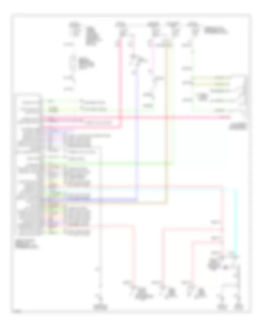
БЛОК УПРАВЛЕНИЯ КУЗОВОМ
Электросхема блока управления кузовом для Infiniti G20 2002
Электросхема блока управления кузовом для Infiniti G20 2002 - Список элементов:
- 10b
- 11b
- Accessory
- Anti-theft system
- B24 (left "b" pillar)
- B7 (right "b" pillar)
- Batt saver output
- Battery (c/b)
- Battery (fuse)
- Central lock sw
- Central unlck sw
- Circuit breaker 1 (behind dash, left of fuse block)
- Computer data lines system
- Condition switch
- Defogger system
- Diode
- Door lock output
- Door locks system
- Door switch
- Door unlk output
- Dr door switch
- Dr door unlck
- Exterior lights system
- Front door switch (driver side)
- Front door switch (passenger side)
- Fuse & fusible link box (left front of engine compartment, next to battery)
- Fuse 10a
- Fuse 7.5a
- Fuse block (j/b) (behind dash, left of steering column)
- Fuse d 30a
- Ground
- Hazard output
- Hood switch
- Horn chirp
- Horns system
- Hot at all times
- Hot in accy or on
- Hot in on or start
- Ignition
- Interior lights system
- Key cyl sw lock
- Key cyl sw unlck
- Key switch
- Left rear door switch
- Light switch
- M15 (behind left kick panel)
- Multi-remote control relay (on fuse block)
- Panic alarm out
- Pass door switch
- Pnk
- Rap output
- Red
- Right rear door switch
- Room lamp output
- Rr def output
- Rr defggr switch
- Seat belt switch
- Security indicator
- Smart entrance control unit (behind dash, left of steering column)
- Trunk key switch
- Trunk output
- Trunk switch
- Trunk, tailgate, fuel doors system
- Warning system
 Русский