AUTOMOTIVE ELECTRICIANS

Электросхемы СИСТЕМА ПЕРЕДАЧИ ДАННЫХ Hyundai Elantra GLS 2001

СИСТЕМА ПЕРЕДАЧИ ДАННЫХ

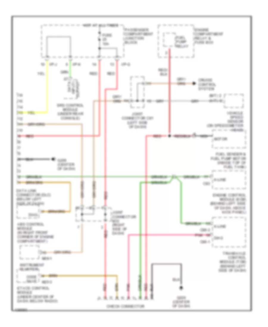
Электросхема компьютерной линии передачи данных CAN для Hyundai Elantra GLS 2001

Электросхема компьютерной линии передачи данных CAN для Hyundai Elantra GLS 2001 - Список элементов:

37
  • (a/t)
  • (m/t)
  • Abs control module (in right front corner of engine compartment)
  • C83
  • C86-1
  • C86-3
  • Check connector
  • Code save
  • Cruise control system
  • Data input/ output
  • Data link connector (dlc) (below left side of dash)
  • Diag
  • Engine compartment relay & fuse box
  • Engine control module (ecm) (behind left side of dash, above kick panel)
  • Etacs control module (under center of dash, below radio)
  • Fuel pump relay
  • Fuel sender & fuel pump motor (inside top of fuel tank)
  • Fuse 10a
  • G206 (center of dash)
  • Hot at all times
  • I/p-g
  • I/p-j
  • I/p-k
  • Instrument cluster
  • Joint connector c91 (left side of dash)
  • Joint connector m33 (right side of dash)
  • K-line
  • M09-1
  • M25-3
  • Motor
  • Nca
  • Passenger compartment junction block
  • Pnk
  • Red
  • Srs control module (under rear console)
  • Transaxle control module (tcm) (behind left side of dash)
  • Vehicle speed sensor (on speedometer head)

Не нашел свой автомобиль? смотри здесь -> DiagnostData.com!