СИСТЕМА ПЕРЕДАЧИ ДАННЫХ
Электросхема компьютерной линии передачи данных CAN для Infiniti Q45 1997
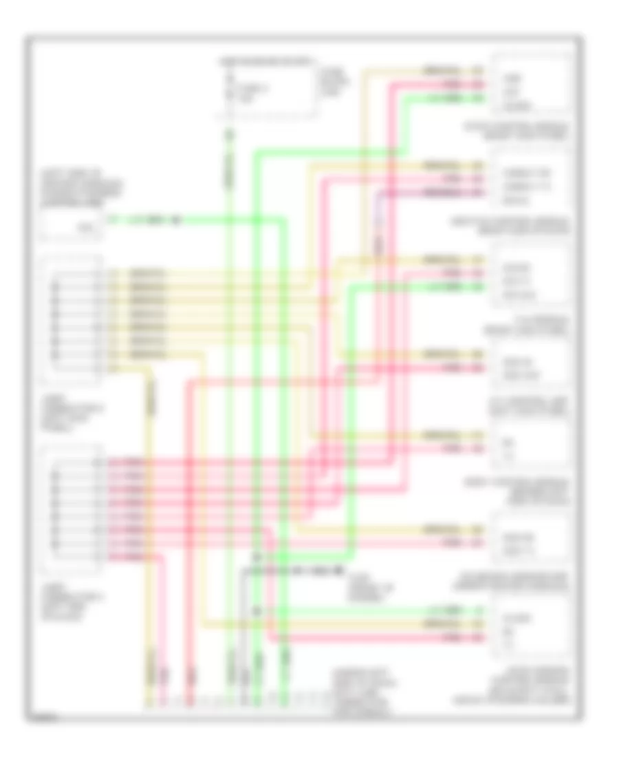
Электросхема компьютерной линии передачи данных CAN для Infiniti Q45 1997 - Список элементов:
- (left side of center console) power steering control unit
- (under left side of dash) data link connector for consult
- A/t control unit (left kick panel)
- Abs/tcs control module (right end of dash)
- Ascd (cruise) control module (on safety wall, above steering column)
- Body control module (behind left side of dash)
- Clock
- Conslt rx
- Conslt tx
- Csr
- Cst
- Diag-l
- Diagnosis sensor unit (under center console)
- Eccs control module (right kick panel)
- Fuse 2 10a
- Fuse block (j/b)
- G125 (front of engine)
- Hot in on or start
- Joint connector 2 (left end of dash)
- Joint connector 8 (left kick panel)
- Pnk
- Red
- Sci clk
- Sci rx
- Sci tx
- Sol
- Sss in
- Sss out
- Sss rx
- Sss tx
- Tac module (right kick panel)
 Čeština
 Dansk
Dansk Deutsch
 Ελληνικά
 English
 English
 Español
 Suomi
Suomi Français
 Français
 עברית
עברית Hrvatski
 Magyar
 Italiano
 日本語
日本語 한국어
한국어 Nederlands
 Polski
 Português
 Português
 Română
 Slovenčina
 Slovenščina
 Svenska
 Türkçe
 中文 (中国)
 Русский