СИСТЕМА УПРАВЛЕНИЯ ДВИГАТЕЛЯ
4.5L
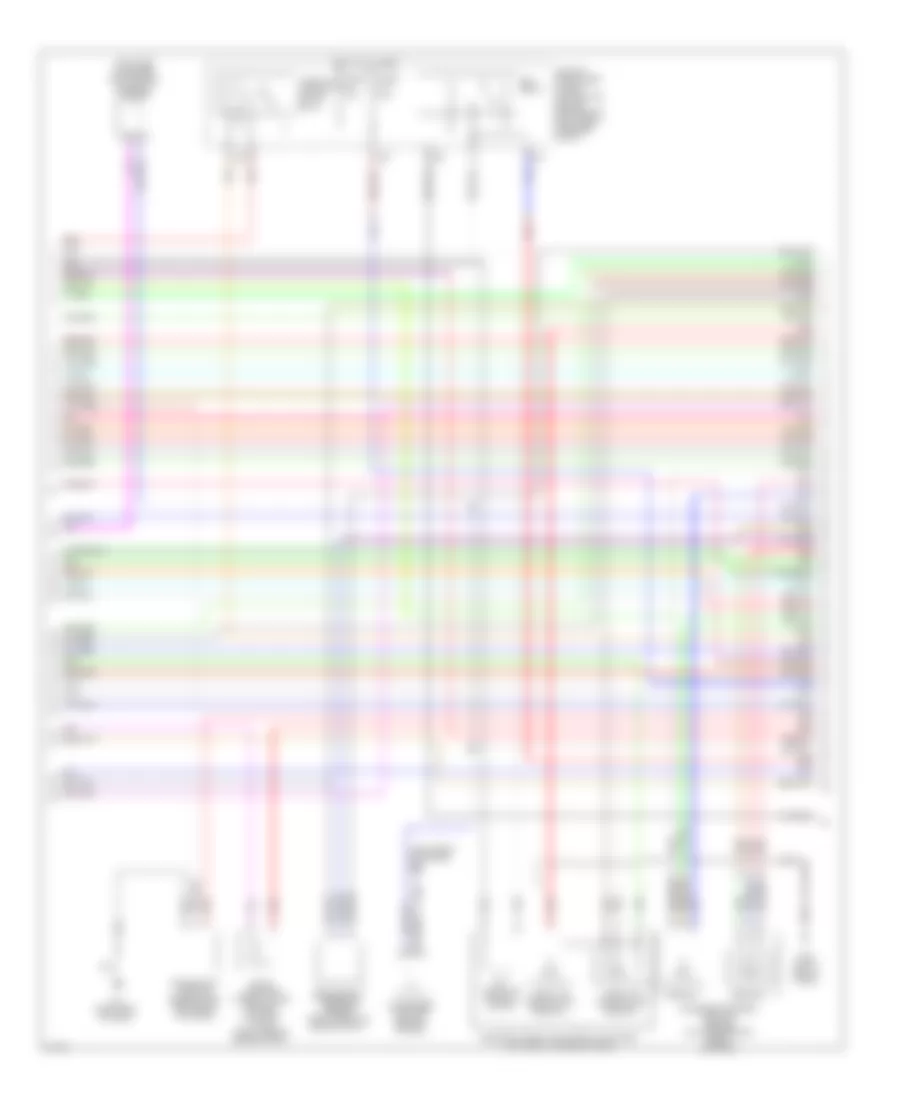
4.5L, Электросхема системы управления двигателя (1 из 5) для Infiniti M45 x 2010

4.5L, Электросхема системы управления двигателя (1 из 5) для Infiniti M45 x 2010 - Список элементов:
- (inj 1, 3, 5, 7: top left of of engine) (inj 2, 4, 6, 8: top right of of engine) fuel injectors
- (right end of dash) m70
- (top left of engine)
- (top right of engine)
- 15a
- A/f-ip1
- Af-h1
- Af-h2
- Af-un1
- Af-vm1
- Af-vm2
- Avcc
- Avcc2
- C-ivc (l)
- C-ivc (r)
- E101
- Ecm (engine control module) (behind right side of dash)
- Evap
- F108
- F22 (left side of engine)
- Fpcm
- Fpcmck
- Ftprs
- Fuse 10a
- Fuse 15a
- Fuse block (j/b) (behind left kick panel)
- Gnd
- Hot at all times
- Hot in on or start
- Ign 7
- Ignition coil 1 (w/ power transistor)
- Ignition coil 2 (w/ power transistor)
- Ignition coil 3 (w/ power transistor)
- Ignition coil 4 (w/ power transistor)
- Ignition coil 5 (w/ power transistor)
- Ignition coil 6 (w/ power transistor)
- Ignition coil 7 (w/ power transistor) (top left of engine)
- Ignition coil 8 (w/ power transistor)
- Inj 1
- Inj 2
- Inj 3
- Inj 4
- Inj 5
- Inj 6
- Inj 7
- Ivc pus (r)
- Knk1
- Knk2
- Knock sensor (bank 1) (top center front of engine)
- Knock sensor (bank 2) (top center front of engine)
- M70 (right end of dash)
- Motor1
- Motor2
- Nca
- O2hrl
- O2hrr
- O2srl
- Pdpres
- Phase
- Plug spark
- Pnk
- Pos
- Ps pres
- Qa+
- Red
- Spark plug
- Tps1
- V mot
- Vias
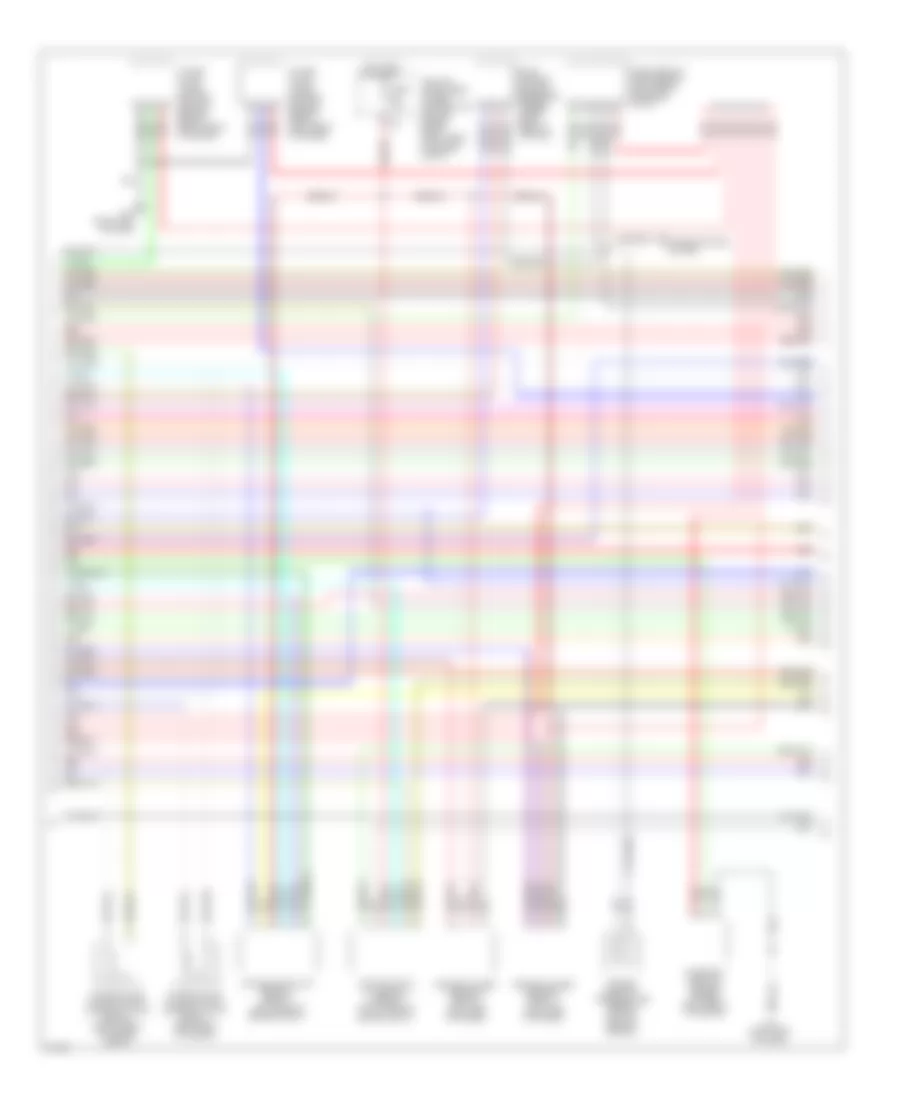
4.5L, Электросхема системы управления двигателя (2 из 5) для Infiniti M45 x 2010
4.5L, Электросхема системы управления двигателя (2 из 5) для Infiniti M45 x 2010 - Список элементов:
- (left front of engine) f44
- (left side of engine) vias control solenoid valve
- Accelerator pedal position sensor (on accelerator pedal bracket)
- Condenser (top left rear of engine)
- Crankshaft position sensor (pos) (left front of engine)
- Ecm relay
- Electric throttle control actuator (left front of engine compt)
- Evap canister purge volume control solenoid valve (right side of engine compt)
- Fuse 15a
- Fuse 20a
- Hot at all times
- Ipdm e/r (intelligent power distribution module engine room) (right rear of engine compt)
- M70 (right end of dash)
- Nca
- Pnk
- Red
- Refrigerant pressure sensor (right front of engine compt)
- Sensor 1
- Sensor 2
- Throttle control motor
- Throttle control motor relay
- Throttle position (tp) sensor 1
- Throttle position (tp) sensor 2
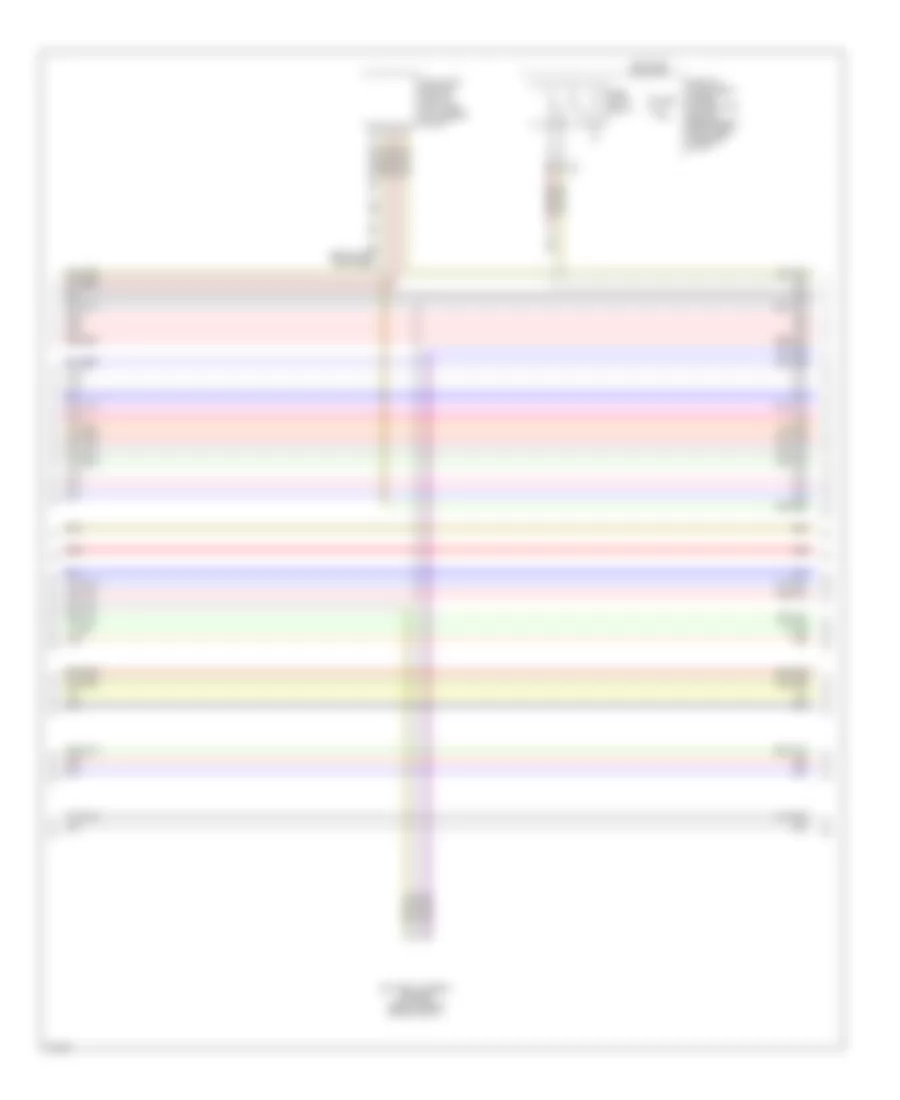
4.5L, Электросхема системы управления двигателя (3 из 5) для Infiniti M45 x 2010
4.5L, Электросхема системы управления двигателя (3 из 5) для Infiniti M45 x 2010 - Список элементов:
- Air fuel ratio (a/f) sensor 1 (bank 1) (left rear of engine compt)
- Air fuel ratio a/f sensor 1 (bank 2) (right rear of engine compt)
- Camshaft position sensor (phase) (left front of engine)
- Cruise control system
- Engine coolant temperature sensor (on top rear of engine)
- Evap control system pressure sensor (under right rear of vehicle)
- Fuse 15a
- Heated oxygen sensor 2 (bank 1) (left side of engine)
- Heated oxygen sensor 2 (bank 2) (left side of engine)
- Hot in on or start
- Intake valve timing control position sensor (bank 1) (left front of engine)
- Intake valve timing control position sensor (bank 2) (right front of engine)
- Intake valve timing control solenoid valve (bank 1) (left front of engine)
- Intake valve timing control solenoid valve (bank 2) (right front of engine compt)
- Ipdm e/r (intelligent power distribution module engine room) (right rear of engine compt)
- M70 (right end of dash)
- Mass airflow (maf) sensor (left front of engine compt)
- Pnk
- Red
4.5L, Электросхема системы управления двигателя (4 из 5) для Infiniti M45 x 2010
4.5L, Электросхема системы управления двигателя (4 из 5) для Infiniti M45 x 2010 - Список элементов:
- B5 (behind left kick panel)
- Battery current sensor (right side of engine compt)
- Fuel pump control module (left side of luggage compt)
- Fuel pump relay
- Fuse 15a
- Hot in on or start
- Ipdm e/r (intelligent power distribution module engine room) (right rear of engine compt)
- Pnk
- Red
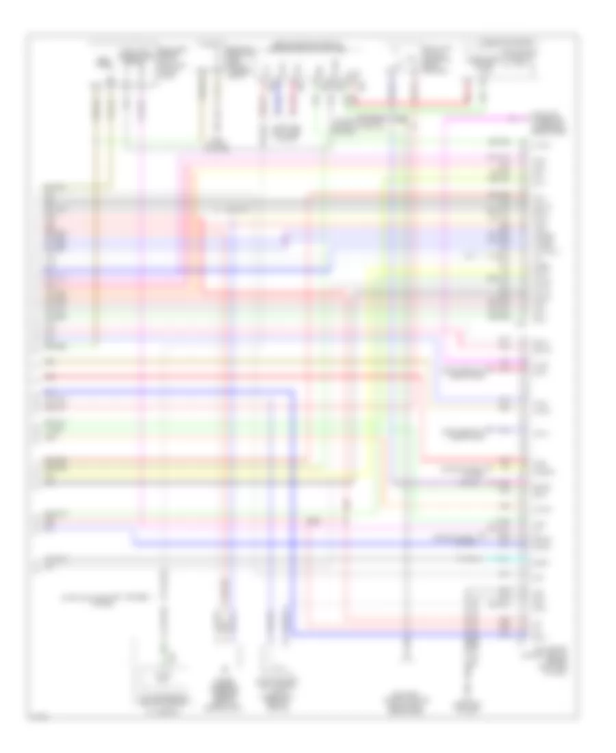
4.5L, Электросхема системы управления двигателя (5 из 5) для Infiniti M45 x 2010
4.5L, Электросхема системы управления двигателя (5 из 5) для Infiniti M45 x 2010 - Список элементов:
- (behind center console) unified meter & a/c amplifier
- A/f-ia1
- A/f-ia2
- A/f-ip2
- A/t assembly
- Af-un2
- Aps1
- Aps2
- Ascdsw
- At-p
- Avcc
- Avcc2
- B40 (at left "c" pillar)
- Batt
- Bcm (body control module) (behind right side of dash)
- Bncsw
- Brake
- Can h
- Can l
- Can-h
- Cdcv
- Combination meter
- Computer data lines system
- Cruise control system
- Cursen
- Data link connector (lower left side of dash)
- Dropping resistor (left side of luggage compt)
- Ecm
- Ecm (engine control module) (behind right side of dash)
- Evap canister vent control valve (under right rear of vehicle)
- F108
- F502
- Fpr
- Fs gnd
- Fuel level sensor unit & fuel pump (in fuel tank)
- Fuel pump
- Fuel tank temperature sensor
- Gnd
- Gnd 02
- Gnd a
- Gnd a2
- Ign 1
- Ign 2
- Ign 3
- Ign 4
- Ign 5
- Ign 6
- Ign 8
- Ign sw
- Inj 8
- Ivc pus (l)
- Kline
- M64
- M65
- M70 (right end of dash)
- M71
- Malfunction indicator
- Motrly
- Nca
- Neut
- O2srr
- Pdpres
- Pnk
- Power steering pressure sensor (front of engine compt)
- Red
- Ssoff
- Start rly
- Starting/charging system
- Stop lamp switch (on brake pedal bracket)
- Tcm (transmission control module)
- Tps2
- Unified meter control unit