СИСТЕМА КОНДИЦИОНЕРА
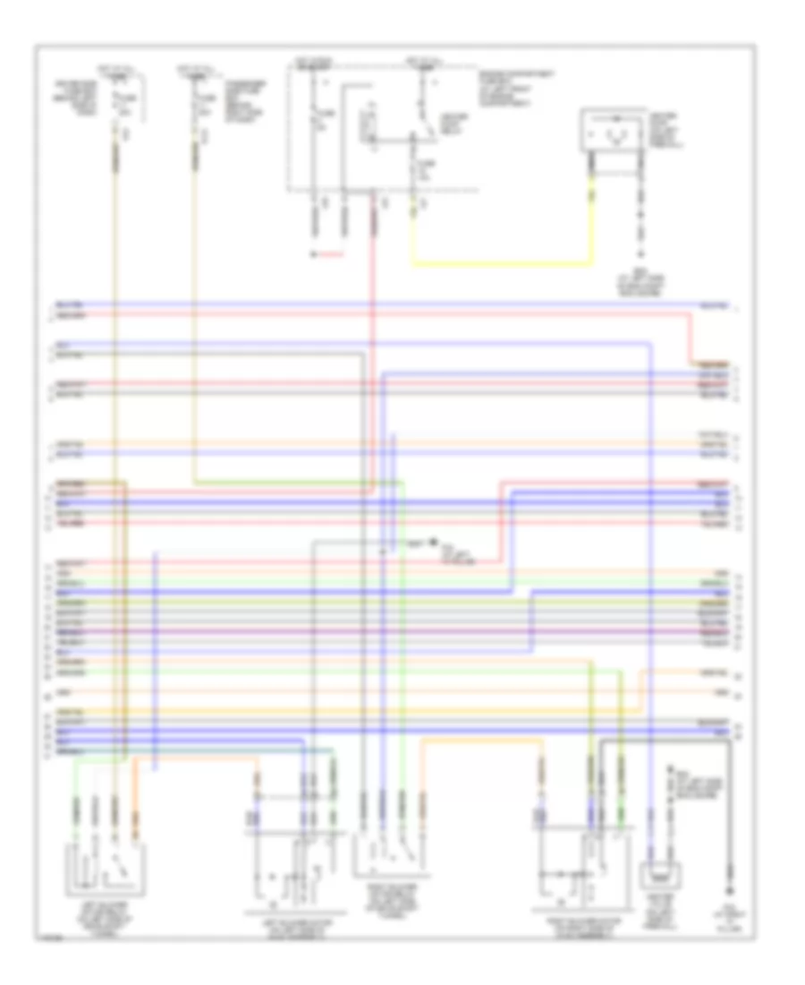
Электросхема кондиционера (1 из 3) для Jaguar XK8 2005
 https://portal-diagnostov.com/license.html
Automotive Electricians Portal FZCO
Automotive Electricians Portal FZCO
https://portal-diagnostov.com/license.html
https://portal-diagnostov.com/license.html
Automotive Electricians Portal FZCO
Automotive Electricians Portal FZCO
Электросхема кондиционера (1 из 3) для Jaguar XK8 2005 - Список элементов:
- (a left front of eng compt) lf2
- 80a
- Ac1
- Ac2
- Air conditioning compressor clutch
- Air conditioning compressor clutch relay (at left rear of engine compartment)
- Air conditioning control module (on right side of hvac assembly)
- Air conditioning pressure sensor (on high pressure refrigerant line)
- Cooling fan module
- Cooling fans fuse box
- Defogger system
- Em19
- Em80
- Engine control module (at right rear of engine compartment, in control module enclosure)
- Engine management fuse box (at right rear of engine compartment, in control module enclosure)
- Fc25
- Fc26
- Fuse 10a
- Hot at all times
- Hot w/ems control relay energized
- Input
- Left blower air intake (at left side of hvac unit)
- Left cooling fan
- Lf15
- Lf35
- Lf36
- Major instrument pack
- Nca
- Output
- Output output
- Red
- Right blower air intake (at right side of hvac unit)
- Right cooling fan
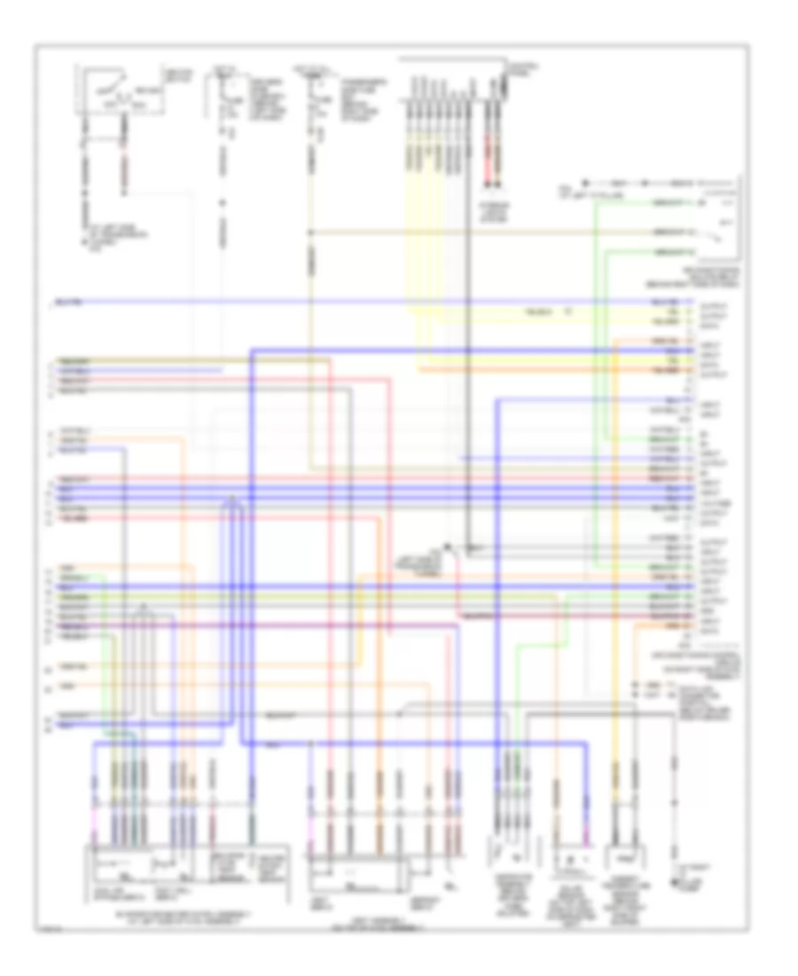
Электросхема кондиционера (2 из 3) для Jaguar XK8 2005
Электросхема кондиционера (2 из 3) для Jaguar XK8 2005 - Список элементов:
- Driver side fuse box (behind left side of dash)
- Em2 (at left side of eng compt enclosure)
- Engine compartment fuse box (at left front of engine compartment)
- Fc2 (at right "a" pillar)
- Fc21
- Fc4 (at left "a" pillar)
- Fc6
- Fuse 10a
- Fuse 20a
- Fuse 5a
- Heater pump (on left side of firewall)
- Heater pump relay
- Heater valve (on left side of firewall)
- Hot at all times
- Hot in run or start
- Left blower motor (on left side of hvac assembly)
- Left blower motor relay (on left side of drive shaft tunnel)
- Lf5
- Lf7
- Lf8
- Nca
- Passenger side fuse box (behind right side of dash)
- Right blower motor (on right side of hvac assembly)
- Right blower motor relay (on left side of drive shaft tunnel)
Электросхема кондиционера (3 из 3) для Jaguar XK8 2005
Электросхема кондиционера (3 из 3) для Jaguar XK8 2005 - Список элементов:
- (at left side of transmission tunnel) fc3
- (at right "a" pillar) fc2br
- Ac3
- Ac4
- Acc
- Air conditioning control module (on right side of hvac assembly)
- Air conditioning isolate relay (behind right side of dash)
- Ambient temperature sensor (behind right front side of bumper)
- Aspirator assembly (behind driver's knee bolster)
- Clock
- Control panel
- Cool air bypass servo
- Data
- Data link connector (partial) (below driver side fuse box)
- Defrost servo
- Dimmer
- Driver's side fuse box (behind left side of dash)
- Evapor- ator temp sensor
- Evaporator/heater matrix assembly (at left side of hvac assembly)
- Fc20
- Fc3 (left side of transmission tunnel)
- Fc4 (at left "a" pillar)
- Fc6
- Foot well servo
- Fuse 10a
- Gnd
- Heater matrix temp sensor
- Hot at all times
- Hot in run
- Ignition switch
- Illum
- Input
- Interior lights system
- Nca
- Off
- Output
- Passenger's side fuse box (behind right side of dash)
- Red
- Run
- Solar sensor (on top left side of dash on defroster vent)
- Start
- Vent assembly (on top of hvac assembly)
- Vent servo
- Voltage

 Čeština
 Dansk
Dansk Deutsch
 Ελληνικά
 English
 English
 Español
 Suomi
Suomi Français
 Français
 עברית
עברית Hrvatski
 Magyar
 Italiano
 日本語
日本語 한국어
한국어 Nederlands
 Polski
 Português
 Português
 Română
 Slovenčina
 Slovenščina
 Svenska
 Türkçe
 中文 (中国)