СИСТЕМА ПЕРЕДАЧИ ДАННЫХ
Электросхема компьютерной линии передачи данных CAN для Jaguar XJR 1997
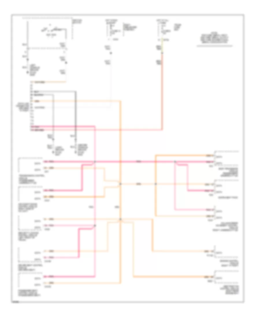
Электросхема компьютерной линии передачи данных CAN для Jaguar XJR 1997 - Список элементов:
- (center console ground stud) g302
- (left console ground stud) g206
- (logic ground stud) g401
- Abs/traction control module (right rear engine bay)
- Acc i
- Air conditioning control module (right side of a/c unit)
- Body processor module (passenger's underscuttle)
- Bt35
- Ca106
- Ca108
- Ca20
- Ca44
- Cc31
- Cc7
- Column/mirror movement control module (right underscuttle)
- Connector (driver's "a" post)
- Data
- Data link
- Driver seat control module (driver's seat)
- Engine control module (right "a" post)
- Fc3
- Fc47
- Fc9
- Fuse 10 5a
- Fuse 6 5a
- Hot at all times
- Hot in run & start
- Ignition switch
- Iii start
- Instrument pack
- Off
- P1105
- Passenger seat control module (passenger's seat)
- Pnk
- Right heelboard fuse box
- Rs27
- Run ii
- Security/locking control module (left front of trunk)
- Transmission control module (passenger's underscuttle)
- Trunk fuse box
 Русский