COOLING FAN
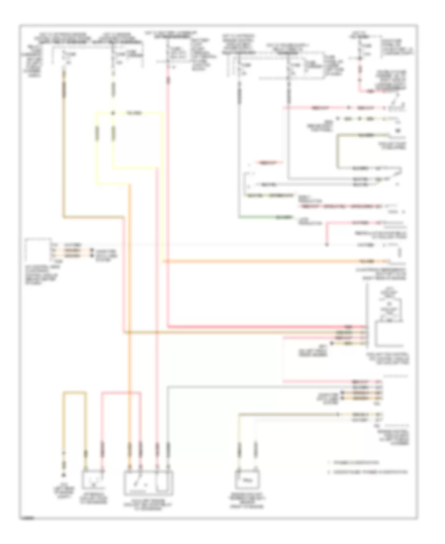
Cooling Fan Wiring Diagram for Audi A5 Quattro 2009
List of elements for Cooling Fan Wiring Diagram for Audi A5 Quattro 2009:
- (a/t) coolant fan 2
- (m/t) (a/t)
- (on relay/fuse carrier - sf, at right side of luggage compt) sockets relay
- 11a
- A/c control head climatronic control module (behind center of dash)
- After-run coolant pump (w/ 8z4/8z6/8z9)
- Auxiliary engine coolant (ec) pump relay (w/ 8z4/8z6/8z9)
- Battery jump start terminal (on terminal 30 wire junction block)
- Climatronic refrigerant shut-off valve (right rear of engine)
- Computer data lines system
- Coolant fan
- Coolant fan control (fc) control module (on coolant fan)
- Coolant pump (if equipped)
- Discontinued, phased in modification
- Early production
- Engine control module (ecm) (in left plenum chamber)
- Engine coolant temperature (ect) sensor (front of engine)
- Fuse 1 40a 60a
- Fuse 110a
- Fuse 15a
- Fuse 5a
- Fuse carrier
- Fuse panel sc (under left side of dash)
- G12 (left rear of engine compt)
- G638 (behind right kick panel)
- G671 (on left front cross member)
- Hot at all times
- Hot w/ battery interrupt igniter energized
- Late production
- Main fuse panel sa (on battery, in luggage compt)
- Phased in modification
- Recirculation pump relay (w/ coolant pump)
- Red
- Relay/ fuse carrier e box sb (in left plenum chamber e-box)
- T20e
- T60
- T94
 Čeština
 Dansk
Dansk Deutsch
 Ελληνικά
 English
 English
 Español
 Suomi
Suomi Français
 Français
 עברית
עברית Hrvatski
 Magyar
 Italiano
 日本語
日本語 한국어
한국어 Nederlands
 Polski
 Português
 Português
 Română
 Slovenčina
 Slovenščina
 Svenska
 Türkçe
 中文 (中国)
 Русский