БЛОК ПРЕДОХРАНИТЕЛЕЙ И РЕЛЕ
2.0L ТУРБО
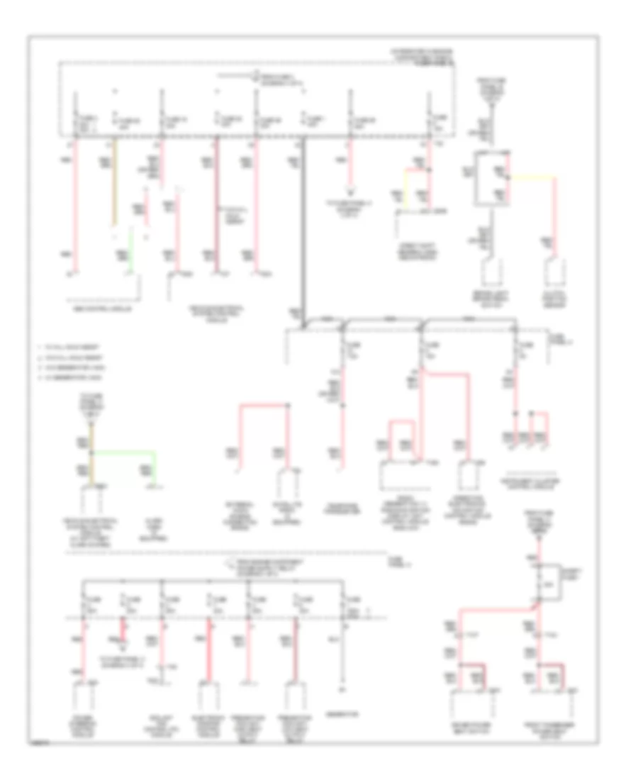
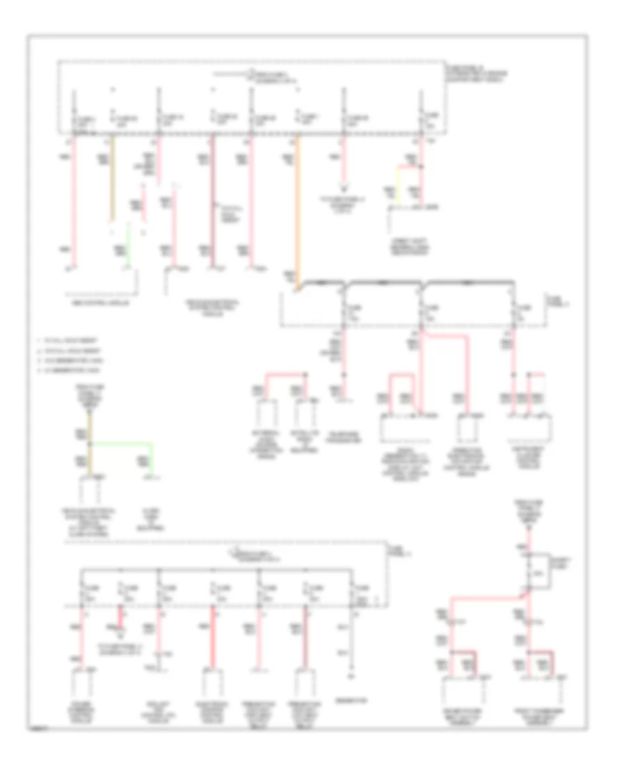
2.0L турбо, Электросхема блока предохранителей и реле (1 из 4) для Audi A3 2.0 TDI 2011

2.0L турбо, Электросхема блока предохранителей и реле (1 из 4) для Audi A3 2.0 TDI 2011 - Список элементов:
- 18a
- 19a
- 20a
- 40a
- 41a
- 47a
- A/c control module (air conditioning w/ manual regulation)
- Abs control module
- Air bag control module
- Air quality sensor
- All- wheel drive control module
- Asr/esp button
- Automatic day/night interior mirror
- Backup light switch (m/t)
- Brake light switch (w/o hill hold assist)
- Cbfa
- Ccta
- Climatronic control module (w/ a/c display control head)
- Data bus on board diagnostic interface
- Data link connector
- Direct shift gearbox (dsg) mechatronic
- Driver seat heater control module
- Electronic damping control module
- Engine control module (ecm)
- Engine control module (ecm) (cbfa)
- From fuse panel b (diagram 4 of 4)
- Front passenger seat heater control module
- Front passenger's air bag disabled indicator lamp
- Fuel pump (fp) control module
- Fuse 10a
- Fuse 15a
- Fuse 18 5a
- Fuse 19 10a
- Fuse 20 5a
- Fuse 40a
- Fuse 47 5a
- Fuse 5 5a
- Fuse 5a
- Fuse 6 5a
- Fuse panel c
- G44 (behind left kick panel)
- Garage door opener control head
- Garage door opener control module
- Generator
- Headlamp range control module
- Heater control module (heater w/ manual regulation)
- High pressure sensor
- Left headlamp assembly
- Left headlamp power output stage
- Left washer nozzle heater (if equipped)
- Light switch
- Mass air flow (maf) sensor & intake air temperature (iat) sensor 2 (ccta) mass air flow (maf) sensor (cbfa)
- Nca
- Oil level thermal sensor
- Parking aid control module
- Positive crankcase ventilation (pcv) heating element (if equipped)
- Power steering control module
- Rear window wiper motor
- Red
- Right headlamp assembly
- Right headlamp power output stage
- Right washer nozzle heater (if equipped)
- Seat occupied recognition control module (if equipped)
- Selector lever sensor system control module
- T10e
- T10k
- T10t
- T10u
- T14c
- T14d
- T16d
- T16f
- T20c
- T20e
- T26a
- T3w
- T52b
- T52c
- T5g
- T6q
- T8b
- T94
- Telephone amplifier (w/o cellular telephone 9zx)
- Tire pressure monitoring button (if equipped)
- Vehicle electrical system control module
- Vehicle electrical system control module (cbfa)
- W/ hill hold assist
- W/o hill hold assist
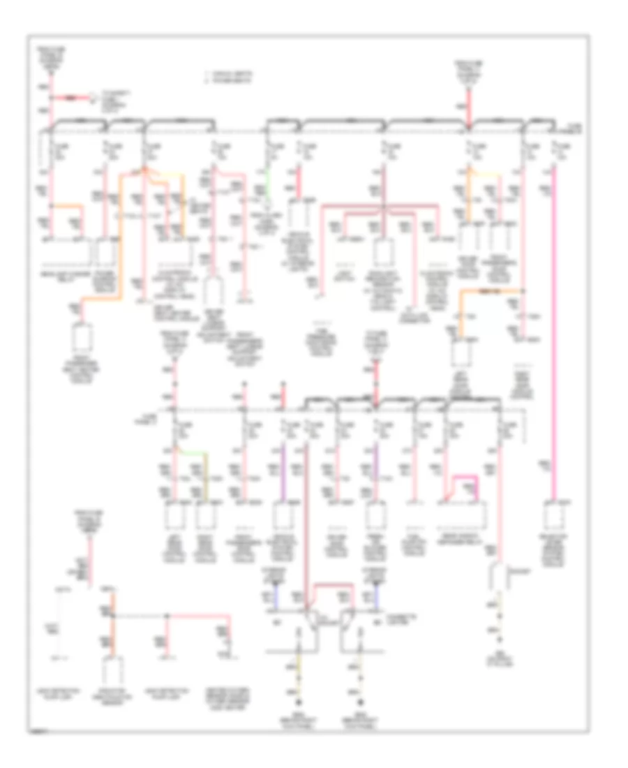
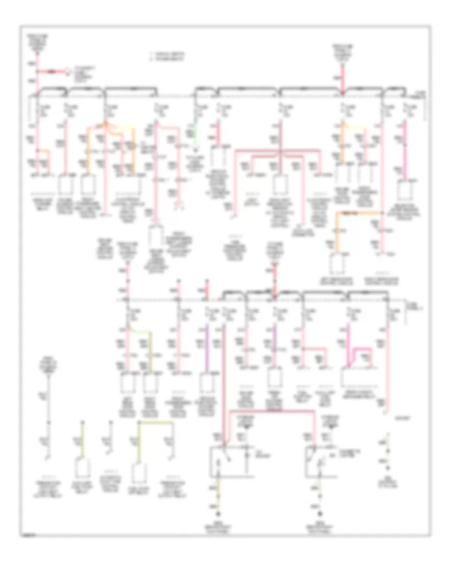
2.0L турбо, Электросхема блока предохранителей и реле (2 из 4) для Audi A3 2.0 TDI 2011
2.0L турбо, Электросхема блока предохранителей и реле (2 из 4) для Audi A3 2.0 TDI 2011 - Список элементов:
- (integrated in engine compartment e-box) fuse panel b
- (rns-e)
- 10a
- 30a
- A/t
- Abs control module
- Alarm horn (if equipped)
- Brake light/ brake pedal switch
- Clutch position sensor
- Coolant fan control (fc) module
- Direct shift gearbox (dsg) mechatronic
- Driver power seat switch
- Electronic damping control module
- External audio source connection (rns-e)
- From fuse 3 (diagram 4 of 4)
- From fuse panel b (diagram 4 of 4)
- From fuse panel c (diagram 3 of 4)
- Front passenger power seat switch
- Fuse 1 40a
- Fuse 150a 200a
- Fuse 15a
- Fuse 16 30a
- Fuse 25 40a
- Fuse 26 30a
- Fuse 28 40a
- Fuse 29 50a
- Fuse 30a
- Fuse 4 20a 30a
- Fuse 40a
- Fuse 50a
- Fuse 5a
- Fuse 7.5a
- Fuse 80a
- Fuse panel a
- Fuse panel c
- Generator
- Instrument cluster control module
- M/t
- Nca
- Operating electronics, navigation control module
- Power steering control module
- Preheating coolant, high heat output relay
- Preheating coolant, low heat output relay
- Radio (generation 11) radio/navigation display unit control module (rns-low)
- Red
- Safety fuse 1
- Satellite radio (if equipped)
- T10t
- T10u
- T16g
- T20e
- T2a
- T2t
- T40
- T4d
- T4w
- T4x
- T52a
- T52c
- T8u
- Telephone transceiver
- To fuse panel c (diagram 3 of 4)
- Vehicle electrical system control module
- Vehicle electrical system control module (w/ anti-theft alarm system)
- W/ generator (140a)
- W/ hill hold assist
- W/o generator (140a)
- W/o hill hold assist
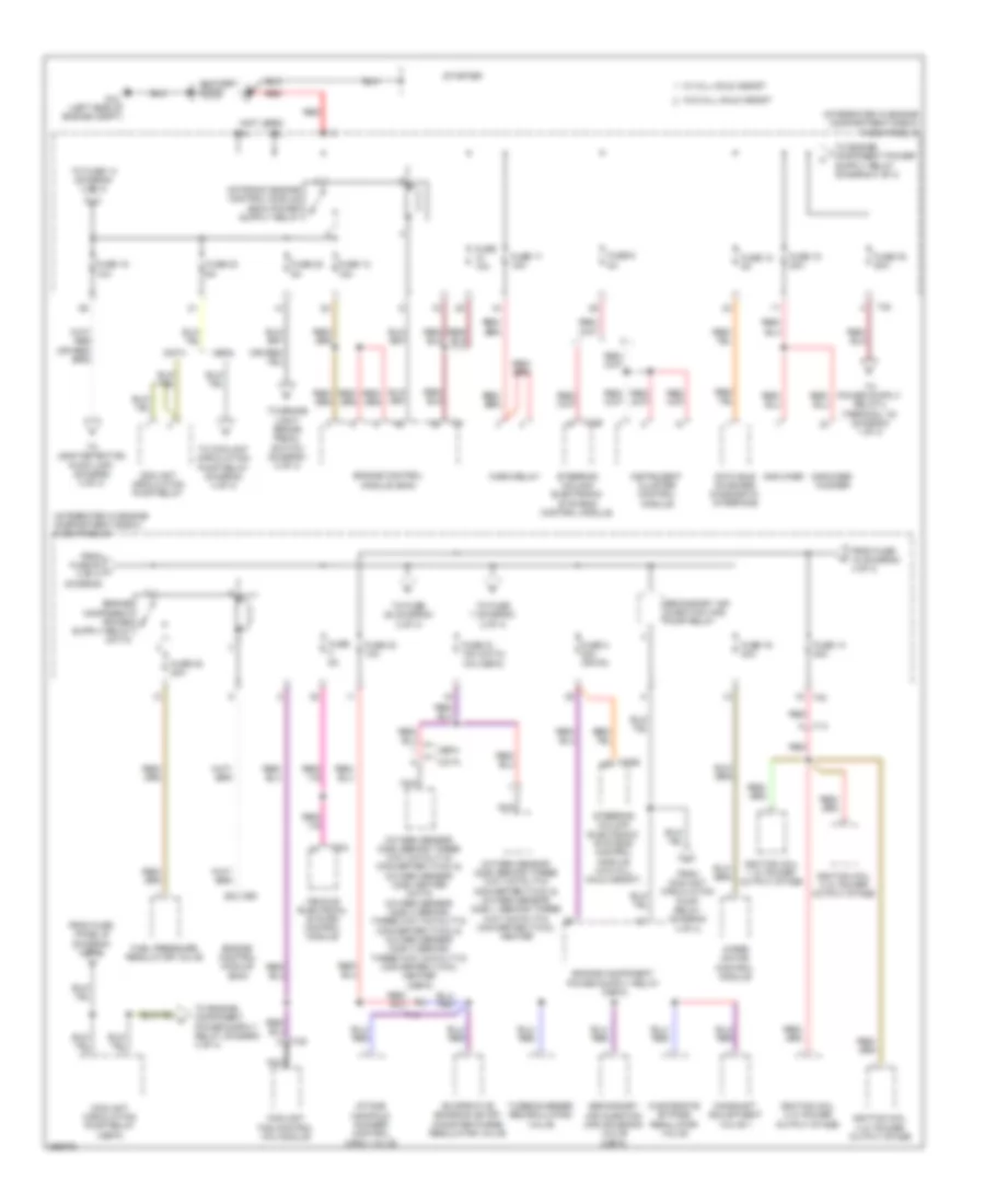
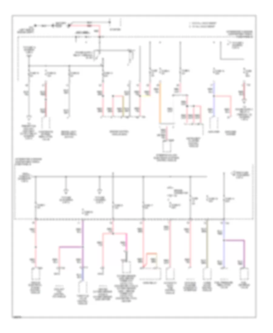
2.0L турбо, Электросхема блока предохранителей и реле (3 из 4) для Audi A3 2.0 TDI 2011
2.0L турбо, Электросхема блока предохранителей и реле (3 из 4) для Audi A3 2.0 TDI 2011 - Список элементов:
- 12a
- 12v socket
- 13a
- 14a
- 15a
- 16a
- 17a
- 22a
- 23a
- 24a
- 25a
- 26a
- 27a
- 28a
- 32a
- 33a
- 36a
- 37a
- 38a
- 43a
- Cbfa
- Ccta
- Cigarette lighter
- Climatronic control module (w/ a/c display control head)
- Data link connector
- Driver door control module
- Driver seat heater control module
- Driver seat lumbar support adjustment switch
- Fresh air blower control module
- From alarm horn (diagram 2 of 4)
- From fuse panel a (diagram 2 of 4)
- From fuse panel b (diagram 2 of 4)
- From fuse panel b (diagram 4 of 4)
- From fuse panel c (diagram 3 of 4)
- Front passenger seat heater control module
- Front passenger's door control module
- Front passenger's seat lumbar support adjustment switch
- Fuel pump (fp) control module
- Fuse 10a
- Fuse 15a
- Fuse 20a
- Fuse 30a
- Fuse 40a
- Fuse 5a
- Fuse panel c
- G62 (on right "c" pillar)
- G638 (behind right kick panel)
- Headlamp washer relay
- Heated oxygen sensor (ho2s) & oxygen sensor (o2s) heater
- Interior lights system
- Leak detection pump (ldp)
- Left rear door control module
- Left rear door module control
- Light switch
- Manual seats
- Nca
- Power seats
- Power sunroof control module
- Radiator identification sensor
- Rain/light recognition sensor (w/ automatic head & taillight control)
- Rear window defogger relay
- Red
- Right rear door control module
- Right rear door module control
- Selector lever sensor system control module
- Socket
- T10a
- T10k
- T10t
- T10u
- T16d
- T20
- T20a
- T20f
- T20g
- T20i
- T20l
- T20m
- T20n
- T20o
- T2bw
- T52b
- T6b
- T8n
- T8o
- Tire pressure monitoring control module
- To fuse panel c (diagram 3 of 4)
- To safety fuse 1 (diagram 2 of 4)
- Vehicle electrical system control module
- Vehicle electrical system control module (w/ interior lights)
- W/ heated seats
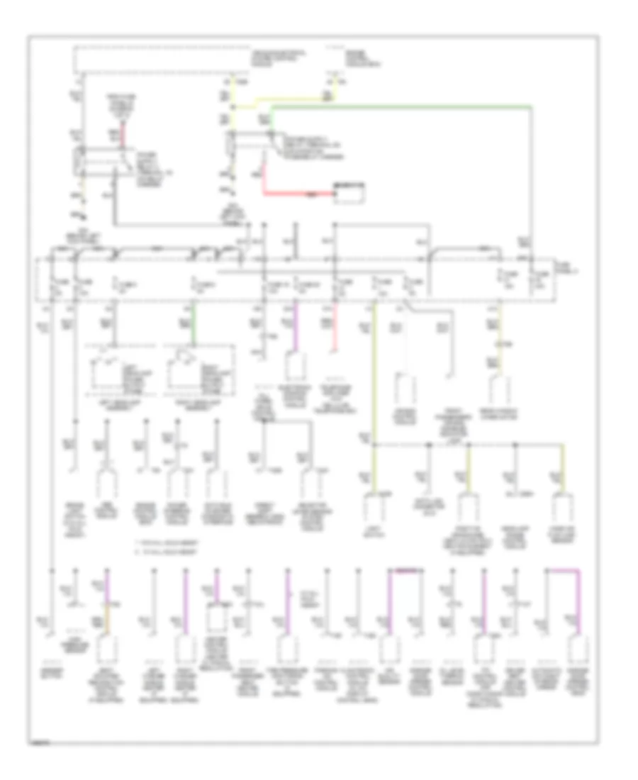
2.0L турбо, Электросхема блока предохранителей и реле (4 из 4) для Audi A3 2.0 TDI 2011
2.0L турбо, Электросхема блока предохранителей и реле (4 из 4) для Audi A3 2.0 TDI 2011 - Список элементов:
- (cbfa)
- (ccta)
- (integrated in engine compartment e-box) fuse panel b
- (not used)
- 10a
- Amplifier
- Amplifier/ woofer
- Battery
- Camshaft adjustment valve 1
- Cbfa
- Ccta
- Coolant circulation pump relay
- Coolant circulation pump relay (cbfa)
- Coolant fan control (fc) module
- Data bus on board diagnostic interface
- Engine control module (ecm)
- Evaprative emission (evap) conister purge regulator valve
- From coolant circulation pump relay (diagram 4 of 4)
- From fuse 15 (diagram 4 of 4)
- From fuse 30 l 4 of 4) (diagram
- From fuse panel b (diagram 4 of 4)
- Fuel pressure regulator valve
- Fuse 10a
- Fuse 12 5a
- Fuse 13 15a
- Fuse 14 20a
- Fuse 15 10a
- Fuse 17 15a
- Fuse 18 30a
- Fuse 19 30a
- Fuse 2 20a (or 5a)
- Fuse 20 20a
- Fuse 21 15a
- Fuse 22 5a
- Fuse 23 5a
- Fuse 24 10a
- Fuse 30 50a
- Fuse 5a
- Fuse 6 5a
- G12 (left side of engine compt)
- Horn relay
- Ignition coil 1 w/ power output stage
- Ignition coil 2 w/ power output stage
- Ignition coil 3 w/ power output stage
- Ignition coil 4 w/ power output stage
- Instrument cluster control module
- Intake manifold runner control (imrc) valve
- Nca
- Oxygen sensor (o2s) (behind three way catalytic converter (twc)) & oxygen sensor (o2s) 1 (behind three way catalytic converter (twc)) heater
- Oxygen sensor (o2s) (behind three way catalytic converter (twc)) & oxygen sensor (o2s) heater (ccta) oxygen sensor (o2s) 3 (behind three way catalytic converter (twc)) & oxygen sensor (o2s) 3 (behind three way catalytic converter (twc)) heater (cbfa)
- Red
- Secondary air injection (air) pump relay
- Secondary air injection (air) solenoid valve (cbfa)
- Starter
- Steering column electronic systems control module
- Steering column electronic systems control module (w/o hill hold assist)
- T14
- T20b
- T40
- T4d
- T52a
- T94
- To brake light/ brake pedal switch (diagram 2 of 4)
- To coolant circulation pump relay (diagram 4 of 4)
- To fuse 14 (diagram 4 of 4)
- To fuse 28 (diagram 2 of 4)
- To fuse 7 (diagram 2 of 4)
- To leak detection pump (ldp) (diagram 3 of 4)
- Turbocharger recirculating valve
- Vehicle electrical system control module
- W/ hill hold assist
- W/o hill hold assist
- Wastegate bypass regulator valve
- Wiper motor control module
2.0L ТУРБО ДИЗЕЛЬ
2.0L турбо дизель, Электросхема блока предохранителей и реле (1 из 4) для Audi A3 2.0 TDI 2011
2.0L турбо дизель, Электросхема блока предохранителей и реле (1 из 4) для Audi A3 2.0 TDI 2011 - Список элементов:
- 19a
- 20a
- 40a
- 41a
- 47a
- A/c control module (air conditioning w/ manual regulation)
- Abs control module
- Air bag control module
- Air quality sensor
- All- wheel drive control module
- Asr/esp button
- Automatic day/night interior mirror
- Brake light switch (w/o hill hold assist)
- Climatronic control module (w/ a/c display control head)
- Data bus on board diagnostic interface
- Data link connector (dlc)
- Direct shift gearbox (dsg) mechatronic
- Driver seat heater control module
- Electronic damping control module
- Engine control module (ecm)
- From fuse panel b (diagram 4 of 4)
- Front passenger seat heater module
- Front passenger's air bag disabled indicator lamp
- Fuse 10a
- Fuse 15a
- Fuse 19 10a
- Fuse 20 5a
- Fuse 40a
- Fuse 5 5a
- Fuse 5a
- Fuse 6 5a
- Fuse panel c
- G44 (behind left kick panel)
- Garage door opener control head
- Garage door opener control module
- Generator
- Headlamp range control module
- Heater control module (heater w/ manual regulation)
- High pressure sensor
- Left headlamp assembly
- Left headlamp power output stage
- Left washer nozzle heater (if equipped)
- Light switch
- Mass air flow (maf) sensor
- Nca
- Oil level thermal sensor
- Parking aid control module
- Positive crankcase ventilation (pcv) heating element (if equipped)
- Power steering control module
- Rear window wiper motor
- Red
- Right headlamp assembly
- Right headlamp power output stage
- Right washer nozzle heater (if equipped)
- Seat occupied recognition control module (if equipped)
- Selector lever sensor system control module
- T10e
- T10k
- T10t
- T10u
- T16d
- T16f
- T20c
- T20e
- T26a
- T3w
- T52b
- T5g
- T6q
- T8b
- T94
- Telephone amplifier (w/o cellular telephone 9zx)
- Tire pressure monitoring button (if equipped)
- Vehicle electrical system control module
- W/ hill hold assist
- W/o hill hold assist
2.0L турбо дизель, Электросхема блока предохранителей и реле (2 из 4) для Audi A3 2.0 TDI 2011
2.0L турбо дизель, Электросхема блока предохранителей и реле (2 из 4) для Audi A3 2.0 TDI 2011 - Список элементов:
- (rns-e)
- 10a
- 30a
- Abs control module
- Alarm horn (if equipped)
- Coolant fan control (fc) module
- Direct shift gearbox (dsg) mechatronic
- Driver power seat switch assembly
- Electronic damping control module
- External audio source connection (rns-e)
- From fuse 3 (diagram 4 of 4)
- From fuse panel c (diagram 3 of 4)
- Front passenger power seat assembly
- Fuse 1 40a
- Fuse 150a 200a
- Fuse 15a
- Fuse 16 30a
- Fuse 25 40a
- Fuse 26 30a
- Fuse 28 40a
- Fuse 29 50a
- Fuse 30a
- Fuse 4 20a
- Fuse 40a
- Fuse 50a
- Fuse 5a
- Fuse 7.5a
- Fuse 80a
- Fuse panel a
- Fuse panel b (integrated in engine compartment e-box)
- Fuse panel c
- Generator
- Instrument cluster control module
- Nca
- Operating electronics, navigation control module
- Power steering control module
- Preheating coolant, high heat output relay
- Preheating coolant, low heat output relay
- Radio (generation 11) radio/navigation display unit control module (rns-low)
- Red
- Safety fuse 1
- Satellite radio (if equipped)
- T16g
- T20e
- T2a
- T2t
- T40
- T4d
- T4w
- T4x
- T52a
- T52c
- T8u
- Telephone transceiver
- To fuse panel c (diagram 3 of 4)
- Vehicle electrical system control module
- Vehicle electrical system control module (w/ anti-theft alarm system)
- W/ generator (140a)
- W/ hill hold assist
- W/o generator (140a)
- W/o hill hold assist
2.0L турбо дизель, Электросхема блока предохранителей и реле (3 из 4) для Audi A3 2.0 TDI 2011
2.0L турбо дизель, Электросхема блока предохранителей и реле (3 из 4) для Audi A3 2.0 TDI 2011 - Список элементов:
- 12a
- 12v socket
- 13a
- 14a
- 15a
- 16a
- 17a
- 22a
- 23a
- 24a
- 25a
- 26a
- 27a
- 28a
- 32a
- 33a
- 36a
- 37a
- 38a
- 43a
- Automatic glow time control module
- Auxiliary fuel pump relay
- Auxillary fuel pump relay
- Cigarette lighter
- Climatronic control module (w/ a/c display control head)
- Data link connector
- Driver door control module
- Driver seat heater control module
- Driver seat lumbar support adjustment switch
- Fresh air blower control module
- From fuse panel a (diagram 2 of 4)
- From fuse panel b (diagram 2 of 4)
- From fuse panel c (diagram 3 of 4)
- From panel b (diagram 4 of 4)
- Front passenger seat heater control module
- Front passenger's door control module
- Front passenger's seat lumbar support adjustment switch
- Fuel pump (fp) relay
- Fuse 10a
- Fuse 15a
- Fuse 20a
- Fuse 30a
- Fuse 40a
- Fuse 5a
- Fuse panel c
- G62 (on right "c" pillar)
- G638 (behind right kick panel)
- Headlamp washer relay
- Interior lights system
- Left rear door control module
- Light switch
- Manual seats
- Nca
- Power seats
- Power sunroof control module
- Preheating coolant, high heat output relay
- Preheating coolant, low heat output relay
- Rain/light recognition sensor (w/ automatic head & taillight control)
- Rear window defogger relay
- Red
- Right rear door control module
- Seats
- Selector lever sensor system control module
- Socket
- T10k
- T10t
- T10u
- T16d
- T20
- T20a
- T20f
- T20g
- T20i
- T20l
- T20m
- T20n
- T20o
- T2bw
- T52b
- T6b
- T8n
- T8o
- Tire pressure monitoring control module
- To alarm horn (diagram 2 of 4)
- To fuse panel c (diagram 3 of 4)
- To safety fuse 1 (diagram 2 of 4)
- Vehicle electrical system control module
- Vehicle electrical system control module (w/ interior lights)
- W/ heated
2.0L турбо дизель, Электросхема блока предохранителей и реле (4 из 4) для Audi A3 2.0 TDI 2011
2.0L турбо дизель, Электросхема блока предохранителей и реле (4 из 4) для Audi A3 2.0 TDI 2011 - Список элементов:
- (integrated in engine compartment e-box) fuse panel b
- (not used)
- Amplifier
- Amplifier/ woofer
- Automatic glow time control module
- Battery
- Brake light/ brake pedal switch
- Bridge connector a2
- Coolant fan control (fc) module
- Data bus on board diagnostic interface
- Engine control module (ecm)
- From fuse 15 (diagram 4 of 4)
- From fuse 30 l (diagram 4 of 4)
- Fuel metering valve
- Fuel pressure regulator valve
- Fuse 13 30a
- Fuse 14 20a
- Fuse 15 5a
- Fuse 17 15a
- Fuse 18 30a
- Fuse 19 30a
- Fuse 2 5a
- Fuse 21 10a
- Fuse 22 5a
- Fuse 23 10a
- Fuse 24 10a
- Fuse 27 50a
- Fuse 3 5a
- Fuse 50a
- Fuse 5a
- Fuse 6 5a
- G12 (left side of engine compt)
- Heated oxygen sensor (ho2s) & oxygen sensor (o2s) heater
- Horn relay
- Instrument cluster control module
- Nca
- Oxygen sensor (o2s) (behind three way catalytic converter (twc)) & oxygen sensor (o2s) 1 (behind three way catalytic converter (twc)) heater
- Red
- Starter
- Steering column electronic systems control module
- T14
- T20b
- T40
- T4d
- T52a
- T94
- Throttle valve control module
- To fuse 14 (diagram 4 of 4)
- To fuse 28 (diagram 2 of 4)
- To fuse 3 (diagram 4 of 4)
- To fuse 7 (diagram 2 of 4)
- To preheating coolant, high heat output relay (diagram 3 of 4)
- Vehicle electrical system control module
- W/ hill hold assist
- W/o hill hold assist
- Wastegate bypass regulator valve
- Wiper motor control module