СИСТЕМА КОНДИЦИОНЕРА
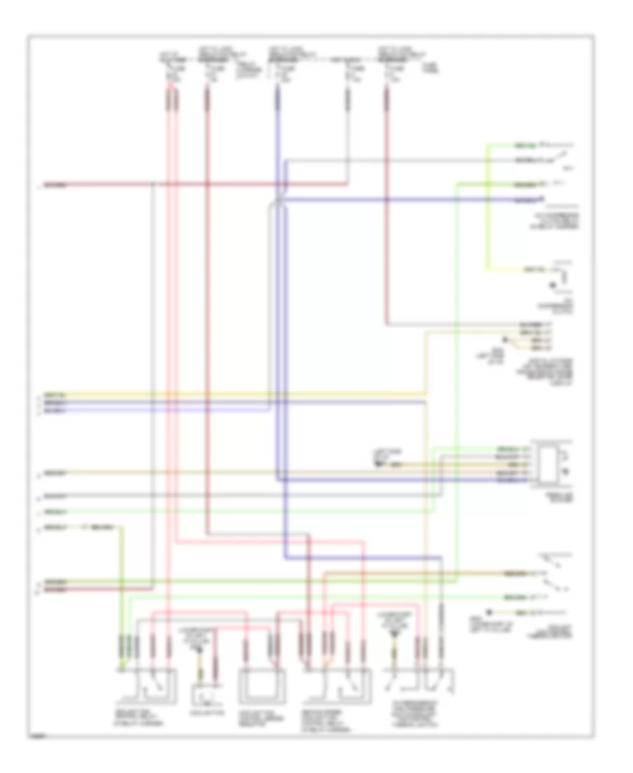
Электросхема кондиционера (1 из 2) для Audi A4 Quattro 1997
 https://portal-diagnostov.com/license.html
Automotive Electricians Portal FZCO
Automotive Electricians Portal FZCO
https://portal-diagnostov.com/license.html
https://portal-diagnostov.com/license.html
Automotive Electricians Portal FZCO
Automotive Electricians Portal FZCO
Электросхема кондиционера (1 из 2) для Audi A4 Quattro 1997 - Список элементов:
- A/c compressor speed sensor
- A/c control head
- Anti-theft system
- Back pressure flap motor and sensor
- Center outlet temperature sender
- Central flap motor and sensor
- Flap motor and sensor
- Floor outlet temperature sender
- Footwell/defroster
- Fresh air intake duct temperature sensor
- Fuse 10a
- Fuse panel
- G202 (left side of i/p)
- Hot at all times
- Instrument cluster
- Interior lights system
- Interior temperature fan & sensor
- Motronic engine control module
- Outside air temperature sensor
- Sunlight photo sensor
- T26
- T26a
- Temperature regulator flap motor and sensor
- Transmission control module
Электросхема кондиционера (2 из 2) для Audi A4 Quattro 1997
Электросхема кондиционера (2 из 2) для Audi A4 Quattro 1997 - Список элементов:
- (in relay carrier)
- (left side of i/p) g202
- (lower part of left "a" pillar) g202
- A/c compressor clutch
- A/c compressor clutch relay (in relay carrier)
- A/c refrigerant
- Coolant fan
- Coolant fan control relay
- Coolant fan control series resistor
- Coolant fan control thermal switch
- Digital outside air temperature/ transmission range selector lever display
- Fan control
- Fresh air blower
- Fuse 10a
- Fuse 30a
- Fuse 40a
- Fuse 5a
- Fuse panel
- G202 (left side of i/p)
- G202 (lower part of left "a" pillar)
- High pressure switch/coolant
- Hot at all times
- Hot in run
- Hot w/ load reduction relay energized
- Relay carrier (8-way)
- Second speed coolant fan control relay
- Thermal switch

 Čeština
 Dansk
Dansk Deutsch
 Ελληνικά
 English
 English
 Español
 Suomi
Suomi Français
 Français
 עברית
עברית Hrvatski
 Magyar
 Italiano
 日本語
日本語 한국어
한국어 Nederlands
 Polski
 Português
 Português
 Română
 Slovenčina
 Slovenščina
 Svenska
 Türkçe
 中文 (中国)