
СИСТЕМА ПЕРЕДАЧИ ДАННЫХ
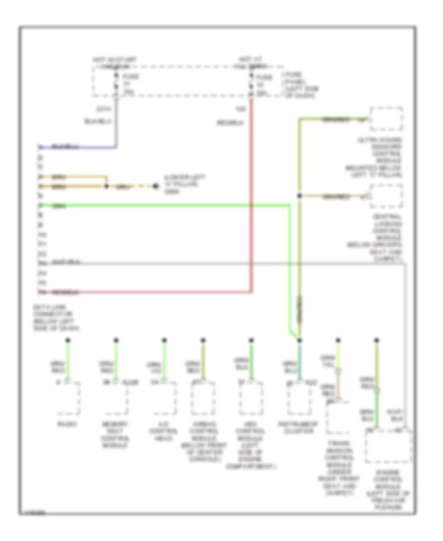
Электросхема линии передачи данных CAN для Audi A6 1999
Электросхема линии передачи данных CAN для Audi A6 1999 - Список элементов:
21
СИСТЕМА КОНДИЦИОНЕРА СИСТЕМА АНТИБЛОКИРОВОЧНОЙ ТОРМОЗНОЙ СИСТЕМЫ ПРОТИВОУГОННАЯ СИСТЕМА СИГНАЛИЗАЦИЯ СИСТЕМА ПЕРЕДАЧИ ДАННЫХ СИСТЕМА ОХЛАЖДЕНИЯ СИСТЕМА КРУИЗКОНТРОЛЯ ПОДОГРЕВ СТЕКОЛ И ЗЕРКАЛ СИСТЕМА УСИЛИТЕЛЯ РУЛЯ СИСТЕМА УПРАВЛЕНИЯ ДВИГАТЕЛЯ ВНЕШНЕЕ ОСВЕЩЕНИЕ ЗАЗЕМЛЕНИЕ ПОДКЛЮЧЕНИЕ МАССЫ СИСТЕМА ФАР ЗВУКОВОЙ СИГНАЛ ГУДОК ПРИБОРНАЯ ПАНЕЛЬ ВНУТРЕННЕЕ ОСВЕЩЕНИЕ СИСТЕМЫ ПАМЯТИ АНТЕННА ПИТАНИЯ БЛОК ПРЕДОХРАНИТЕЛЕЙ И РЕЛЕ ЦЕНТРАЛЬНЫЙ ЗАМОК СИСТЕМЫ СИДЕНИЙ ПРИВОД ЛЮКА И КРЫШИ ПРИВОД СТЕКЛОПОДЪЕМНИКОВ МАГНИТОЛА МУЛЬТИМЕДИЯ БЛОКИРОВКИ СЕЛЕКТОРА СТОЯНОЧНЫЙ ТОРМОЗ СТАРТЕР ГЕНЕРАТОР ПОДУШКИ БЕЗОПАСНОСТИ СИСТЕМА ПРИВОДА БАГАЖНИК ЗАДНЯЯ ДВЕРЬ ЛЮЧОК ТОПЛИВНОГО БАКА ПРЕДУПРЕЖДАЮЩИЕ СИСТЕМЫ СТЕКЛООЧИСТИТЕЛИ И СТЕКЛООМЫВАТЕЛИ ДВОРНИКИ