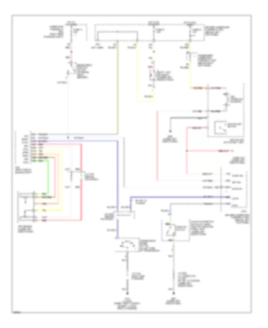
SHIFT INTERLOCK
Shift Interlock Wiring Diagram for Honda Odyssey LX 2010
List of elements for Shift Interlock Wiring Diagram for Honda Odyssey LX 2010:
- (behind glove box)
- (behind left kick panel)
- (not used)
- A16
- A18
- A19
- A24
- A25
- A26
- A27
- App sensor (under left side of dash)
- Apsa
- Apsb
- Atp-p
- Bksw
- Brake pedal position switch (on brake pedal bracket)
- D3 switch/park pin switch/a/t gear position indicator panel light (under left side of dash)
- Driver's under-dash fuse/relay box
- Driver's under-dash fuse/relay box (behind left kick panel)
- E16
- Ex, ex-l & touring
- Fuse 13 20a
- Fuse 21 7.5a
- Fuse 32 10a
- G101 (lx & ex: under throttle body) (except lx & ex: front of engine)
- G501 (under left side of dash)
- G502 (under left side of dash)
- Hot at all times
- Hot in acc or on
- Hot in on or start
- Ig key sw
- Ignition key switch
- Ignition key switch/key light
- Imoes unit (under left side of dash)
- J/c c102 (right side of engine)
- J/c c405 (behind glove box)
- J/c c407
- J/c c502 (lx; canada; dx) j/c c501 (ex, ex-l & touring) (under left side of dash)
- Key interlock solenoid
- Key sol
- Micu
- N26
- N36
- Of engine compt)
- P-pin
- P13
- P29
- P30
- Park pin switch
- Passenger's under-dash fuse/relay box (behind right kick panel)
- Pcm (right side of engine compt)
- Red
- Sg3
- Sg4
- Shift lock solenoid (under left side of dash)
- Sls
- Stop sw
- Transmission range switch (on left side of transmission)
- Under-hood fuse/relay box (right rear
- Vcc3
- Vcc4
- X34
 Čeština
 Dansk
Dansk Deutsch
 Ελληνικά
 English
 English
 Español
 Suomi
Suomi Français
 Français
 עברית
עברית Hrvatski
 Magyar
 Italiano
 日本語
日本語 한국어
한국어 Nederlands
 Polski
 Português
 Português
 Română
 Slovenčina
 Slovenščina
 Svenska
 Türkçe
 中文 (中国)
 Русский