БЛОК ПРЕДОХРАНИТЕЛЕЙ И РЕЛЕ
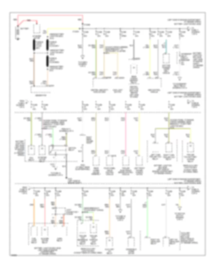
Электросхема блока предохранителей и реле (1 из 4) для Lincoln Aviator 2004
Электросхема блока предохранителей и реле (1 из 4) для Lincoln Aviator 2004 - Список элементов:
74
- (at right rear quarterpanel)
- (in dash panel to engine wiring harness, near breakout to battery junction box) s129
- (in main wiring harness, near breakout to instrument cluster) s213
- (in right rear of cargo area)
- (left side of engine compartment, at fender apron) battery junction box (bjb)
- (near battery junction box) s101
- (near battery junction box) s102
- (near battery junction box) s103
- (near breakout to main body wiring) s419
- Abs control module
- Accessory delay circuit breaker 30a
- Auxiliary a/c relay
- Auxiliary junction box (ajb) (right side of engine compt, at fender apron)
- Battery
- Battery junction box (bjb) (left side of engine compartment, at fender apron)
- Battery junction box (bjb) (left side of engine compt, at fender apron)
- Blower motor relay
- C102a
- C1035a
- C1035b
- C205a
- C270c
- C281b
- C3008e
- Central junction box (cjb) (behind left side of dash)
- Central security module (csm)
- Charge relay
- Daytime running lamps (drl) module
- Four wheel drive control module
- From fuse 19 (diagram 1 of 4)
- From fuse 6 (diagram 1 of 4)
- From s111 (diagram 4 of 4)
- Fuel pump relay
- Fuse 20a
- Fuse 30a
- Fuse 40a
- Fuse 50a
- Fuse 60a
- Fuse open
- G107 (left side of engine compt)
- G402
- Generator
- Horn relay
- Ignition relay
- Joint connector 1 (in bjb)
- Left front power window motor
- Left hid headlamp relay
- Left turn trailer tow relay
- Main light switch
- Pcm relay
- Rear auxiliary junction box
- Rear auxiliary junction box (in right rear of cargo area)
- Rear window defrost relay
- Rear wiper motor assembly
- Red
- Right hid headlamp relay
- Right rear power point
- Right turn
- Starter motor
- Starter motor relay
- To accessory delay relay (diagram 3 of 4)
- To fuse 10 (diagram 3 of 4)
- To fuse 11 (diagram 1 of 4)
- To fuse 15 (diagram 3 of 4)
- To fuse 16 (diagram 4 of 4)
- To fuse 26 (diagram 1 of 4)
- To fuse 5 (diagram 3 of 4)
- To ignition switch (diagram 2 of 4)
- Trailer electronic brake control module
- Trailer tow battery
- Trailer tow parking lamp relay
- Trailer tow relay
- Trailer tow reversing lamps relay
- Windshield wiper motor
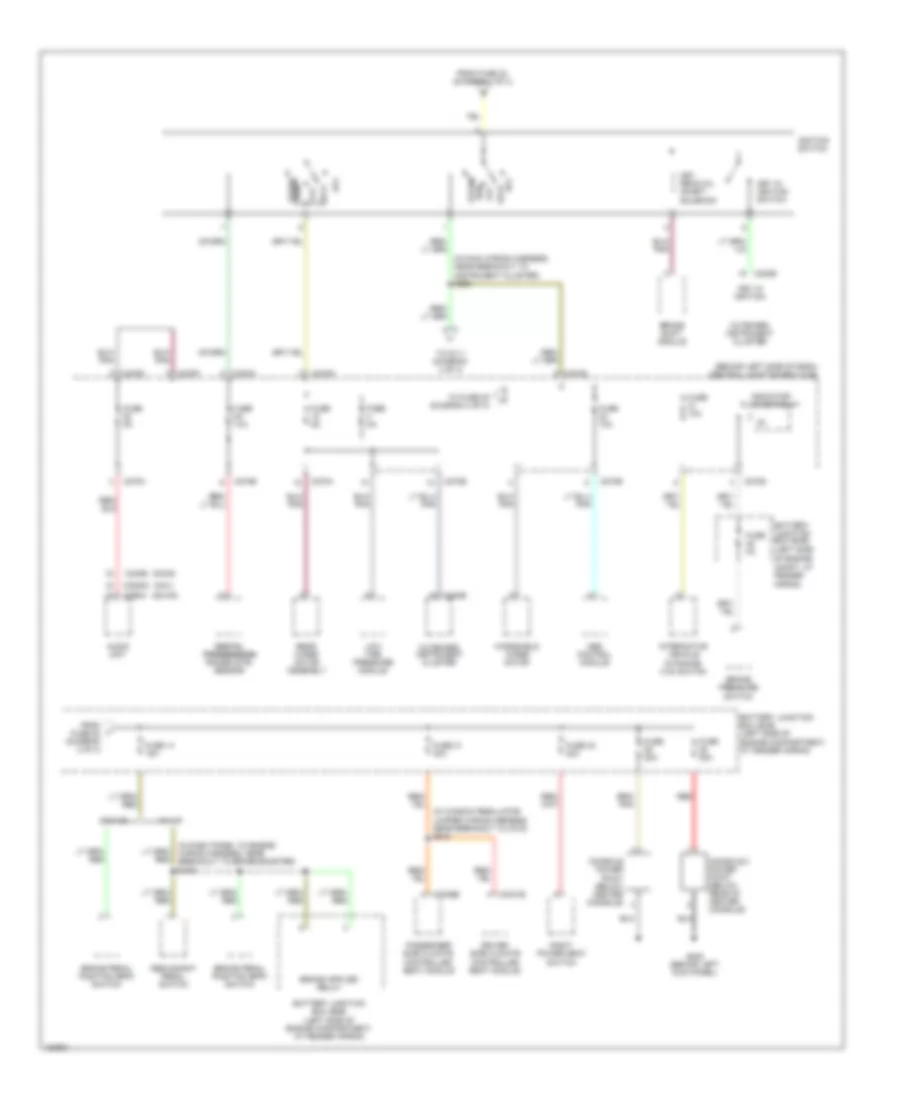
Электросхема блока предохранителей и реле (2 из 4) для Lincoln Aviator 2004
Электросхема блока предохранителей и реле (2 из 4) для Lincoln Aviator 2004 - Список элементов:
67
- (behind left side of dash) central junction box (cjb)
- (cdx6)
- (dm100)
- (in dash panel to engine wiring harness, near breakout to brake booster) s109
- (in main wiring harness, near breakout to instrument cluster) s229
- (in window regulator jumper wiring harness, near breakout to c315) s343
- (left side
- (nav)
- Abs control module
- Acc
- Audio unit
- Battery junction box (bjb)
- Battery junction box (bjb) (left side of engine compartment, at fender apron)
- Brake pedal position (bpp) switch
- Brake pressure switch
- Brake shift module
- C220b
- C2253c
- C240b
- C270a
- C270b
- C270d
- C270e
- C270f
- C270g
- C270h
- C290a
- C3031b
- C3036b
- Console 2 power point (below rear of center console)
- Console power point (below center console)
- Digital digital transmission transmission range (dtr) sensor
- Driver side climate controlled seat module
- Dynamics (ivd) switch
- From fuse 22 (diagram 3 of 4)
- From fuse 23 (diagram 1 of 4)
- Fuse 10a
- Fuse 14 15a
- Fuse 20a
- Fuse 2a
- Fuse 31 30a
- Fuse 32 30a
- Fuse 5a
- G205 (behind left kick panel)
- Ignition switch
- Indicator flasher relay
- Interactive vehicle
- Key in ignition
- Key in ignition switch
- Key removal inhibit solenoid
- Lock
- Low tire pressure module
- Of engine compt, at fender apron)
- Off
- Outboard instrument cluster
- Passenger side climate controlled seat module
- Rear wiper motor assembly
- Red
- Redundant pedal switch
- Right power seat switch
- Run
- Start
- To fuse 25 (diagram 4 of 4)
- To s111 (diagram 4 of 4)
- W/ ivd
- W/o ivd
- Windshield wiper motor
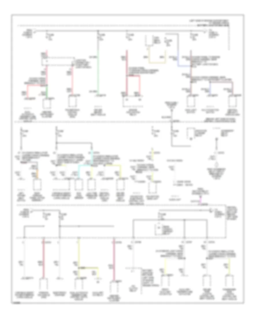
Электросхема блока предохранителей и реле (3 из 4) для Lincoln Aviator 2004
Электросхема блока предохранителей и реле (3 из 4) для Lincoln Aviator 2004 - Список элементов:
78
- (behind left side of dash) central junction box (cjb)
- (cdx6)
- (dm100)
- (in dash panel to engine wiring harness, in engine compartment) s126
- (in interior lamp wiring harness, near breakout to c3047) s306
- (in main wiring harness, near breakout to c219) s219
- (in window regulator jumper wiring harness, near breakout to c315) s337
- (left side
- (left side of engine compartment, at fender apron) battery junction box (bjb)
- A/c clutch relay
- Accessory delay relay
- Audio unit
- Auxiliary a/c relay
- Auxiliary temperature actuator
- Battery junction box (bjb)
- C175b
- C202c
- C205a
- C220a
- C2231a
- C2253c
- C228b
- C240b
- C270a
- C270b
- C270c
- C270d
- C270f
- C270h
- C290a
- C3008e
- C341e
- C341g
- C4209a
- C938a
- Central junction box (cjb) (behind left side of dash)
- Central security module (csm)
- Driver memory seat module
- Driver side climate controlled seat module
- Dual automatic temperature control (datc) module
- Electronic compass
- Engine cooling fan relay
- From accessory delay circuit breaker 401 (diagram 1 of 4)
- From fuse 1 (diagram 1 of 4)
- From fuse 23 (diagram 1 of 4)
- From fuse 26 (diagram 4 of 4)
- From ignition relay (diagram 1 of 4)
- Front auxiliary a/c switch
- Fuse 10a
- Fuse 15a
- Fuse 20a
- Fuse 30a
- Fuse 5a
- High beam relay
- Inboard instrument cluster
- Indicator flasher relay
- Junction connector 1 (in battery junction box)
- Left power seat switch
- Low tire pressure module
- Main body wiring) s335
- Main light switch
- Multi-function switch
- Navigation electronic control unit (ecu) module
- Navigation head unit
- Of engine compt, at fender apron)
- Parking aid module (pam)
- Passenger side climate controlled seat module
- Powertrain control module (pcm)
- Rear window defrost relay
- Roof opening panel motor assembly
- S223
- Sun load sensor
- To fuse 14 (diagram 2 of 4)
- To fuse 8 (diagram 4 of 4)
- Variable assist power steering (vaps) module
- W/ nav radio
- W/o nav radio
- Wiring harness, near breakout to battery junction box) s130
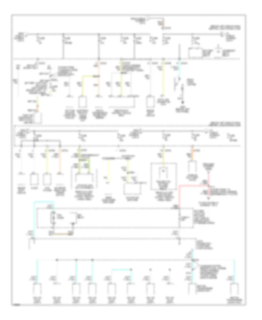
Электросхема блока предохранителей и реле (4 из 4) для Lincoln Aviator 2004
Электросхема блока предохранителей и реле (4 из 4) для Lincoln Aviator 2004 - Список элементов:
71
- (behind left side of dash) central junction box (cjb)
- (in dash panel to engine wiring harness, in engine compt)
- (in engine control sensor & fuel charge wiring harness, near breakout to right rear side of engine)
- (in main
- Accessory delay relay
- Battery junction box (bjb) (left side of engine compt, at fender apron)
- Battery saver relay
- Brake shift module
- C270a
- C270c
- C270e
- C270f
- C270g
- C310a
- C4211a
- Cdx6 radio
- Clock
- Coil on plug (cop) 1
- Coil on plug (cop) 2
- Coil on plug (cop) 3
- Coil on plug (cop) 4
- Coil on plug (cop) 5
- Coil on plug (cop) 6
- Coil on plug (cop) 7
- Coil on plug (cop) 8
- Data link connector (dlc)
- Daytime running lamps (drl) module
- Digital transmission range (dtr) sensor
- Dvd player
- Eletroch- romatic inside mirror unit
- Exterior rear view mirror switch
- From fuse 17 (diagram 4 of 4)
- From fuse 22 (diagram 2 of 4)
- From fuse 29 f (diagram 1 of 4)
- From k fuse 10 (diagram 3 of 4)
- From s229 (diagram 2 of 4)
- Front cigar lighter
- Fuse 10a
- Fuse 15a
- Fuse 20a
- Fuse 30a
- Fuse 41 25a
- Fuse 5a
- Fuse 7.5a
- Fuse open
- Fuse spare
- G205 (behind left kick panel)
- Ignition transformer capacitor 1
- Ignition transformer capacitor 2
- Joint connector 1 (in battery junction box)
- Liftgate lock actuator relay
- Navigation amplifier
- Navigation radio
- Passive anti-theft (pats)
- Pcm diode
- Pcm relay
- Positive crankshaft ventilation heater
- Rear auxiliary junction box (in right rear of cargo area)
- Rear subwoofer amplifier
- Restraints control module (rcm)
- S111 (in dash panel to engine wiring harness, near breakout to c133)
- S138
- S143
- S228
- S232
- To fuse 20 (diagram 4 of 4)
- To fuse 27 (diagram 3 of 4)
- To ignition relay (diagram 1 of 4)
- Trailer tow battery charge relay
- W/ drl
- W/o drl