AIR CONDITIONING
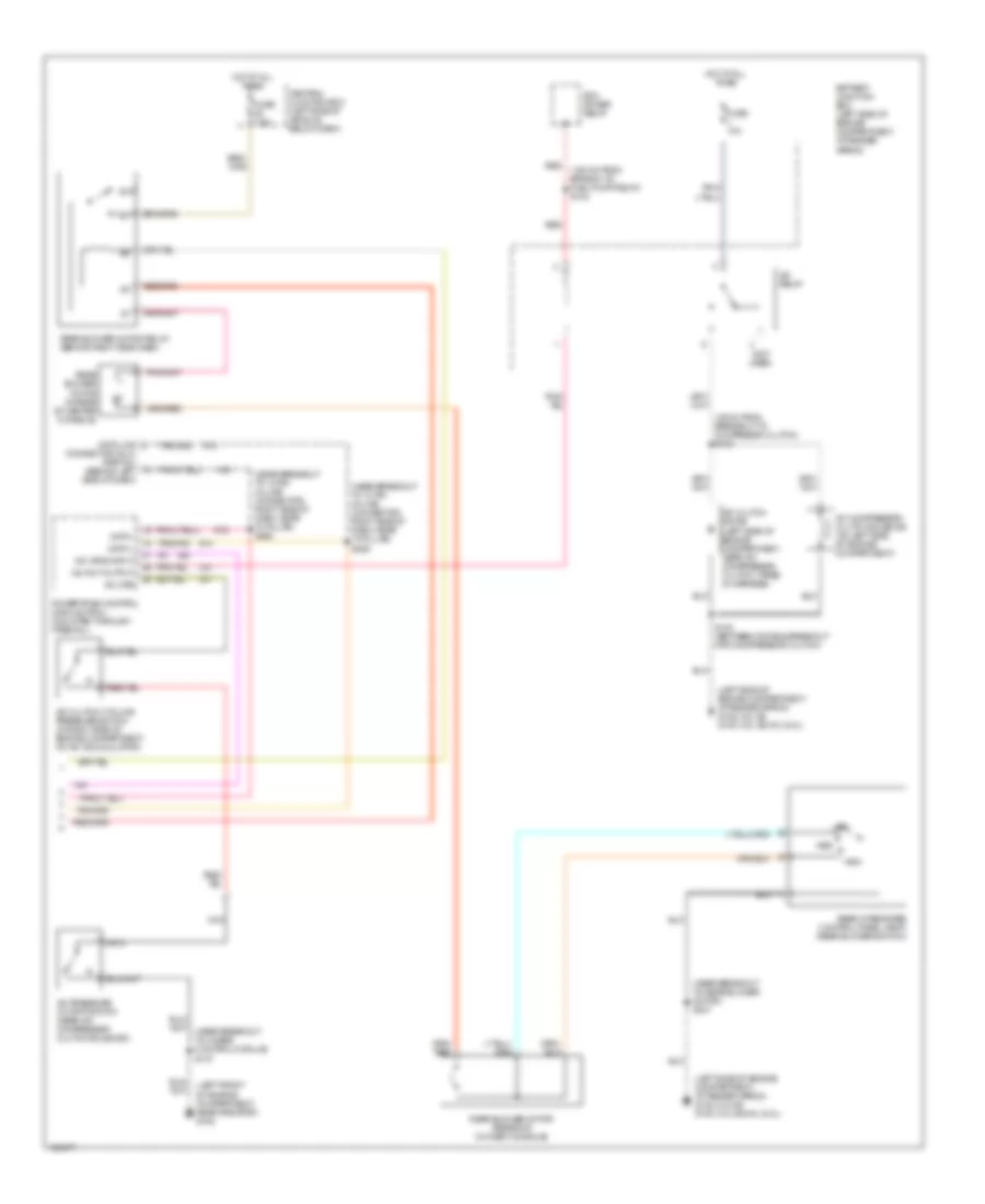
Automatic A/C Wiring Diagram (1 of 2) for Mercury Mountaineer 2001
 https://portal-diagnostov.com/license.html
Automotive Electricians Portal FZCO
Automotive Electricians Portal FZCO
https://portal-diagnostov.com/license.html
https://portal-diagnostov.com/license.html
Automotive Electricians Portal FZCO
Automotive Electricians Portal FZCO
List of elements for Automatic A/C Wiring Diagram (1 of 2) for Mercury Mountaineer 2001:
- (left side of engine compartment, at fender apron) g102 (4.0l ei) g100 (4.0l sohc) (5.0l)
- (near breakout for instrument cluster) s209
- (near breakout to central junction box) s217
- (near breakout to radio) s200
- (near breakout to rear window defrost relay) s263
- (not used)
- (right side of engine compartment, attached to right quarter panel) g101 (4.0l sohc) g103 (4.0l ei, 5.0l)
- 87a
- A/c demand
- Air bag sliding contact
- Amb temp sens input
- Ambient air temperature sensor (left front of engine compartment)
- Audio/climate control switch assembly
- Battery
- Battery junction box (left side of engine compartment, at fender apron)
- Blend door act 5v+
- Blend door act gnd
- Blend door actuator
- Blend door actuator (behind right side of dash, top of a/c plenum)
- Blend door ref
- Blower motor (right side of engine compartment)
- Blower motor relay
- Blower motor speed controller (near blower motor)
- Blower mtr fback
- Blower mtr rly gnd
- Blwr mtr rly out
- Breakout to rear blower motor relay) s210
- C297
- C298
- Central junction box (left side of vehicle, below dash)
- Climate control switch
- Cruise control
- Data (+)
- Data (-)
- Eatc to sliding cont
- Electronic automatic temperature control (eatc) module (behind center of dash)
- English/metric in
- Fan
- Fuse 7.5a
- Fuse 2 40a
- Ground
- Hot at all times
- Hot in run
- Ignition power
- Illumination
- In car temp sens
- In-car temperature sensor (behind top center of dash)
- Input ground
- Instrument illum
- Interior lights system
- Lamp illumination
- Message center
- Nca
- Ohms
- Rear blwr rly gnd
- Red
- Solid state
- Sound systems
- Speed control servo (in right rear of engine compartment)
- Speed ctrl out
- Speed ctrl sw gnd
- Sun load sensor (top right side of dash, above glove box)
- Sunload sens input
- Temp
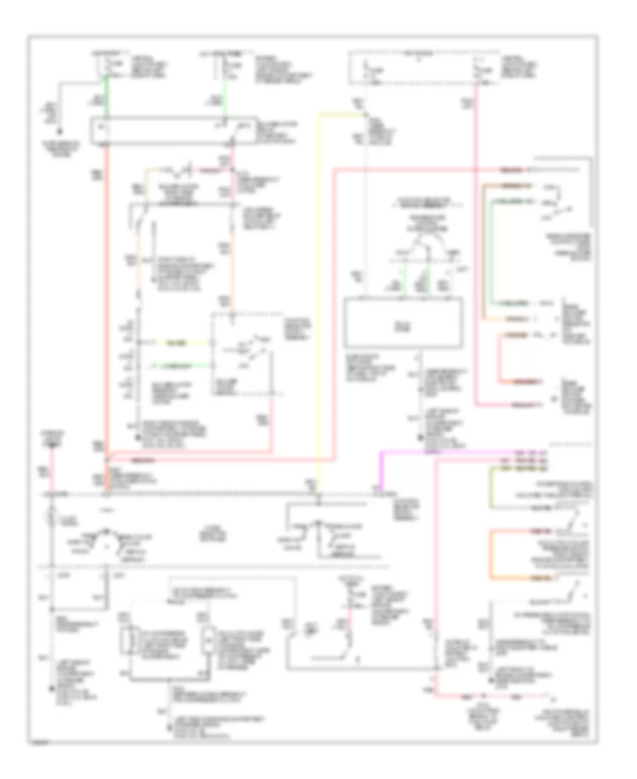
Automatic A/C Wiring Diagram (2 of 2) for Mercury Mountaineer 2001
List of elements for Automatic A/C Wiring Diagram (2 of 2) for Mercury Mountaineer 2001:
- (135 mm from branch to fuel pump relay) s123
- (25 mm from breakout to compresor clutch) s133
- (left front of engine compartment, near radiator) g108
- (left side of engine compartment, at fender apron) g102 (4.0l ei) g100 (4.0l sohc) (5.0l)
- (near breakout to 10 pin in-line connector, right side of dash, near "a" pillar) s205
- (near breakout to 10 pin in-line connector, right side of dash, near "a" pillar) s206
- (near breakout to 4wabs control module) s137
- (near breakout to rear blower motor) s231
- (not used)
- 87a
- A/c clutch cycling pressure switch (in right side of engine compartment, on a/c accumulator)
- A/c clutch diode (left side of engine compartment, near a/c compressor clutch, taped in harness)
- A/c compressor clutch solenoid (on left side of engine compartment)
- A/c cps
- A/c hpcs input
- A/c pressure cutoff switch (near a/c compressor clutch solenoid)
- A/c relay
- A/c wot output
- Battery junction box (left side of engine compartment, at fender apron)
- Central junction box (left side of vehicle, below dash)
- Connector (dlc) (partial) (behind left side of dash)
- Data +
- Data -
- Data link
- Fuse 7.5a
- Fuse 10a
- High
- Hot at all times
- Low
- Med
- Nca
- Pcm power relay
- Powertrain control module (pcm) (mounted through firewall)
- Rear blower motor (in rear of center console)
- Rear blower motor relay (behind right side dash)
- Rear blower motor resistor (in dash console)
- Rear integrated control panel (ricp) (rear blower switch)
- Red
- S100 (between diode & breakout for compressor clutch)
Manual A/C Wiring Diagram for Mercury Mountaineer 2001
List of elements for Manual A/C Wiring Diagram for Mercury Mountaineer 2001:
- (25 mm from breakout to compressor clutch) s133
- (left front of engine compartment, near radiator) g108
- (left side of engine compartment, at fender apron) g102 (4.0l ei) g100 (4.0l sohc & 5.0l)
- (left side of engine compartment, at fender apron) g102 (4.0l ei) g100 (4.ol sohc & 5.0l)
- (near breakout for generic electronic module (gem)) s229
- (near breakout to positive battery cable) s159
- (not used)
- (right side of engine compartment, attached to right quarter panel) g101 (4.0l sohc) g103 (4.0l ei, 5.0l)
- .25 ohms +/- 10%
- .8 ohms +/- 10%
- 2.7 ohms +/- 10%
- 87a
- A/c clutch cycling pressure switch (right side of engine compartment, at a/c accumulator)
- A/c clutch diode (left front side of engine compartment, near a/c compressor clutch, taped in harness)
- A/c compressor clutch solenoid (left front side of engine compartment)
- A/c pressure cutoff switch (near breakout to a/c compressor clutch solenoid)
- A/c relay (mounted in battery junction box)
- Battery junction box (left side of engine compartment, at fender apron)
- Blend door actuator (behind right side of dash, top of a/c plenum)
- Blower motor (right side of engine compartment)
- Blower motor relay (in battery junction box)
- Blower motor resistor (near blower motor)
- Blower motor switch
- C231
- C276
- C277
- Central junction box (behind left side of dash)
- Cold
- Def/flr
- Defrost
- Engine compartment, attached to right quarter panel) g101 (4.0l sohc) g103 (4.0l ei, 5.0l)
- Floor
- Function selector switch assembly
- Fuse 7.5a
- Fuse 10a
- Fuse 40a
- Fuse 7.5a
- High
- High speed blower relay (in auxiliary relay box 1)
- Hot at all times
- Hot in run
- Illumi- nation
- Interior lights system
- Low
- Max a/c
- Med
- Mode selector switches
- Norm a/c
- Off
- Off panel
- Panel
- Panel/floor
- Pcm power relay (mounted in battery junction box at right fender apron)
- Powertrain control module (pcm) (mounted through firewall)
- Rear blower motor (in rear of center console)
- Rear blower motor resistor (in center console)
- Rear integrated control panel (ricp) (rear blower switch)
- Red
- S100 (between diode & breakout for compressor clutch)
- S123 (135 mm from branch to fuel pump relay)
- S170 (near breakout to blower motor)
- S200 (near breakout to radio)
- S244 (near breakout to relay module)
- Solid state
- Temperature control potentiometer
- To blower motor switch)
- Warm

 Čeština
 Dansk
Dansk Deutsch
 Ελληνικά
 English
 English
 Español
 Suomi
Suomi Français
 Français
 עברית
עברית Hrvatski
 Magyar
 Italiano
 日本語
日本語 한국어
한국어 Nederlands
 Polski
 Português
 Português
 Română
 Slovenčina
 Slovenščina
 Svenska
 Türkçe
 中文 (中国)