ANTI-LOCK BRAKES
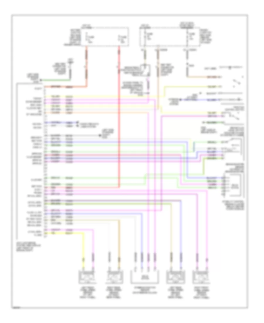
Anti-lock Brakes Wiring Diagram for Ford Explorer Sport Trac 2009
List of elements for Anti-lock Brakes Wiring Diagram for Ford Explorer Sport Trac 2009:
- (in dash panel to engine harness, near breakout to left front of vehicle) s128
- (left side of engine compt) g105
- (not used)
- Abs test connector (left side of engine compt)
- Anti-lock brake system (abs) module (left front of engine compt)
- Battery junction box (bjb) (left side of engine compt, at fender apron)
- Boo logic
- Bpfs nc
- Bpfs no
- Bpfs sig
- Brake booster sensor (on front of brake booster)
- Brake fluid level switch (mounted on side of master cylinder)
- Brake pedal position switch (above brake pedal)
- Bst pwm
- Bst pwr
- C2280c
- C2280e
- Can2 hi
- Can2 lo
- Cbp18
- Cca09
- Cca15
- Cca22
- Cca25
- Cca26
- Cca29
- Ccb08
- Ccs01
- Clus gnd
- Clus sensep
- Cmc19
- Computer data lines system
- Fl gnd
- Fluid lvl sw
- Fluid sw ret
- Fr gnd
- Fuse 10a
- Fuse 15a
- Fuse 30a
- Fuse 40a
- G105 (left side of engine compt)
- G200 (at right kick panel)
- Gd120
- Ground p
- Hot at all times
- Hot w/ run/ start relay energized
- Hs can+
- Hs can-
- Ign
- Interior lights system
- Kl30 p
- Kl30 v
- Left front wheel speed sensor (at left front wheel)
- Left rear wheel speed sensor (at left rear wheel)
- Lf whl spd+
- Lr whl spd+
- Lr whl spd-
- Rca09
- Rca17
- Rca18
- Rca19
- Rca20
- Rcs02
- Red
- Rf whl spd+
- Right front wheel speed sensor (at right front wheel)
- Right rear wheel speed sensor (at right rear wheel)
- Rmc19
- Rr whl spd+
- Rr whl spd-
- S208
- Sbb06
- Sbb33
- Smart junction box (sjb) (behind left side of dash)
- Solid state
- St ang 1(cha)
- St ang 2(chb)
- Stability control sensor cluster (below center floor console)
- Steering position sensor (on steering column)
- Swar gnd
- Swar sensep
- Tcs sw
- Traction control switch
- Vca03
- Vca04
- Vca05
- Vca06
- Vca22
- Vca23
- Vca24
- Vcs06
- Vcs07
- Vdb04
- Vdb05
 Čeština
 Dansk
Dansk Deutsch
 Ελληνικά
 English
 English
 Español
 Suomi
Suomi Français
 Français
 עברית
עברית Hrvatski
 Magyar
 Italiano
 日本語
日本語 한국어
한국어 Nederlands
 Polski
 Português
 Português
 Română
 Slovenčina
 Slovenščina
 Svenska
 Türkçe
 中文 (中国)
 Русский