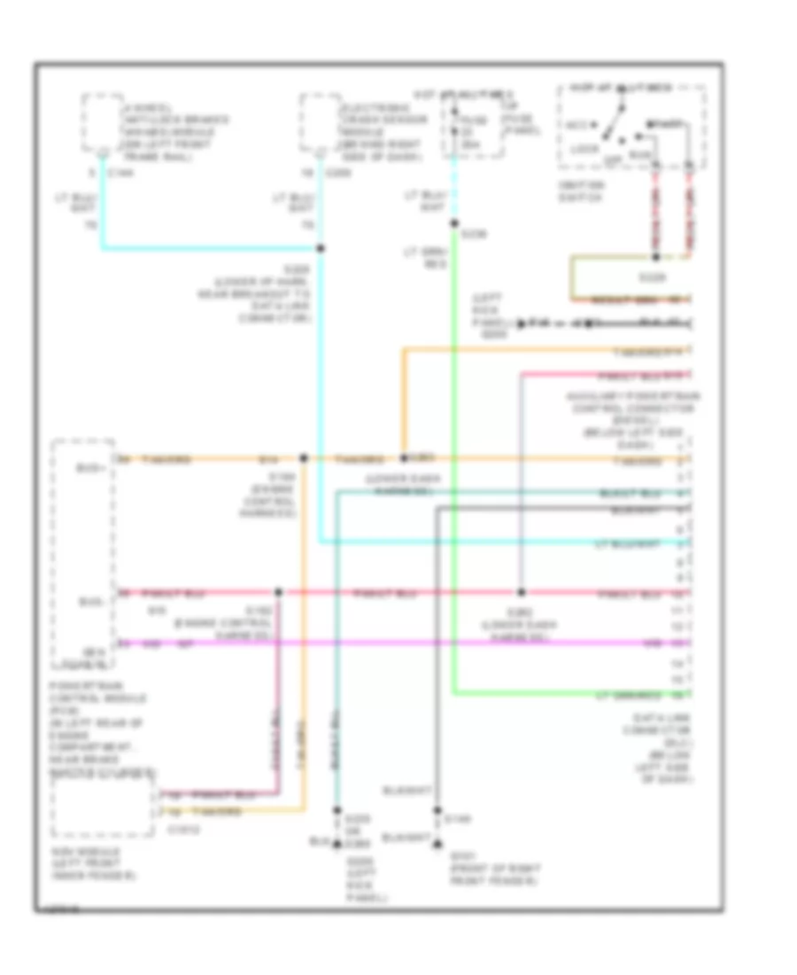
COMPUTER DATA LINES
Computer Data Lines Wiring Diagram for Ford Econoline E250 2001
List of elements for Computer Data Lines Wiring Diagram for Ford Econoline E250 2001:
- (left kick panel)
- (lower dash harness)
- 4 wheel anti-lock brakes (4wabs) module (on left front frame rail)
- Acc
- Auxiliary powertrain control connector (diesel) (below left side dash)
- Bus+
- Bus-
- C1012
- C144
- C200
- Data link connector (dlc) (below left side of dash)
- Electronic crash sensor module (behind right side of dash)
- Fuse 20a
- G101 (front of right front fender)
- G200
- G200 (left kick panel)
- Gen scan in
- Hot at all times
- I/p fuse panel
- Ignition switch
- Lock
- Ngv module (left front inner fender)
- Off
- Powertrain control module (pcm) (in left rear of engine compartment, near brake master cylinder)
- Run
- S140
- S182 (engine control harness)
- S184 (engine control harness)
- S223
- S228 (lower i/p harn, near breakout to data link connector)
- S229
- S230
- S235 or s260
- S262 (lower dash harness)
- S263
- Start
 Čeština
 Dansk
Dansk Deutsch
 Ελληνικά
 English
 English
 Español
 Suomi
Suomi Français
 Français
 עברית
עברית Hrvatski
 Magyar
 Italiano
 日本語
日本語 한국어
한국어 Nederlands
 Polski
 Português
 Português
 Română
 Slovenčina
 Slovenščina
 Svenska
 Türkçe
 中文 (中国)
 Русский