AUTOMOTIVE ELECTRICIANS

Электросхемы СИСТЕМА АНТИБЛОКИРОВОЧНОЙ ТОРМОЗНОЙ СИСТЕМЫ ABS Ford Escape 2004

СИСТЕМА АНТИБЛОКИРОВОЧНОЙ ТОРМОЗНОЙ СИСТЕМЫ ABS

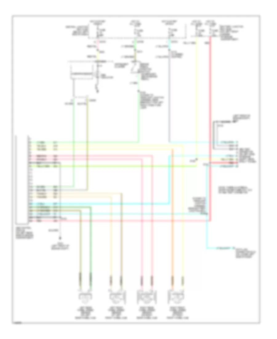
Электросхема антиблокировочной тормозной системы АБС (ABS) для Ford Escape 2004

Электросхема антиблокировочной тормозной системы АБС (ABS) для Ford Escape 2004 - Список элементов:

40

  • (in dash to headlamp junction harness, near battery junction box) s125
  • (left front of engine compt) g104
  • Abs control module (on left rear side of engine compartment)
  • Abs indicator
  • Abs test connector (on left side of engine compt, near
  • Battery junction box (bjb) (on left front corner of engine compartment)
  • Brake pedal position switch (on bracket, above brake pedal)
  • C220b
  • C220c
  • C270a
  • C270c
  • C270e
  • Central junction box (cjb) (below left end of dash)
  • Data link connector (dlc) (on lower left side of dash)
  • Fuse 10a
  • Fuse 15a
  • Fuse 25a
  • Fuse 5a
  • Fuse 60a
  • G104 (left front of engine compt)
  • Hot at all times
  • Hot in start or run
  • Instrument cluster
  • Left front wheel speed sensor (at left front wheel hub)
  • Left rear wheel speed sensor (on left rear wheel hub)
  • Microprocessor
  • Note: there is internal shorting between pin 1 & 5 of abs test connector
  • Red
  • Red/pnk
  • Right front wheel speed sensor (at right front wheel hub)
  • Right rear wheel speed sensor (on right rear wheel hub)
  • S119 (w/ speed control)
  • S123
  • S124
  • S126
  • S132
  • S139 (in dash to headlamp junction harness, near breakout for left front park/turn lamp)
  • S222
  • S314
  • Strut tower)

Не нашел свой автомобиль? смотри здесь -> DiagnostData.com!