AIR CONDITIONING
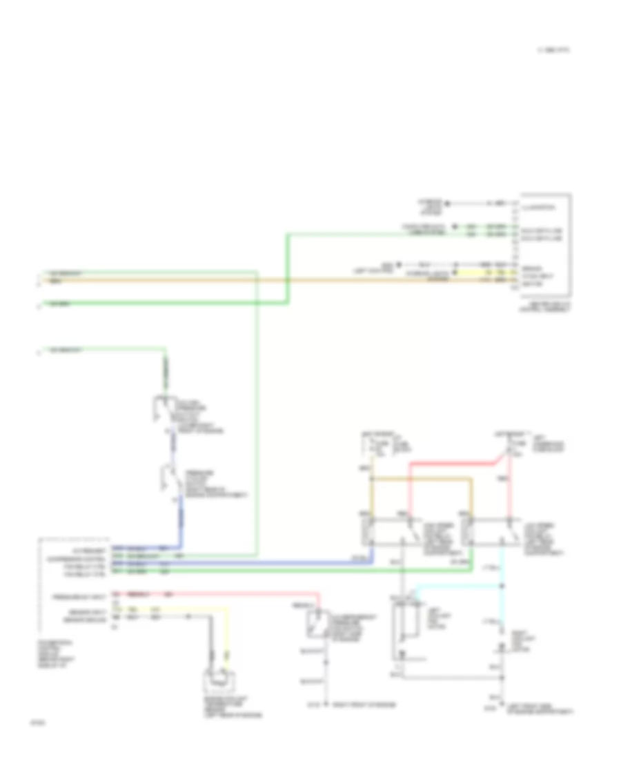
A/C Wiring Diagram, Auto A/C (1 of 2) for Pontiac Bonneville SE 1995
 https://portal-diagnostov.com/license.html
Automotive Electricians Portal FZCO
Automotive Electricians Portal FZCO
https://portal-diagnostov.com/license.html
https://portal-diagnostov.com/license.html
Automotive Electricians Portal FZCO
Automotive Electricians Portal FZCO
List of elements for A/C Wiring Diagram, Auto A/C (1 of 2) for Pontiac Bonneville SE 1995:
- (top left side of i/p)
- +5v
- A/c compres- sor clutch
- A/c compres- sor clutch diode
- A/c compressor control relay (center rear of engine compartment)
- A/c request
- Air mix valve actuator
- Ambient temperature sensor (center front of vehicle)
- Battery
- Blower control module (center rear of engine compartment)
- Blower control output
- Blower feedback
- Blower motor
- C 1995 vftc
- C10
- C11
- C12
- C13
- C14
- C15
- C16
- Computer data lines system
- D10
- D11
- D12
- D13
- D14
- D15
- D16
- Data line
- Data link connector (below left side of i/p)
- E & c data line
- Fuse 10a
- Fuse 15a
- Fuse 30a
- Fuse 5a 10a
- Fuse 9c 10a
- G101 (right front of engine compartment)
- G203 (right kickpad)
- Ground
- Hot at all times
- Hot at run, bulb test, or start
- Hot in run
- Hvac programmer (behind right side of i/p)
- I/p fuse block
- Ignition
- In-vehicle temperature sensor (behind center of i/p)
- Motor control
- Motor ctrl
- Motor feedback
- Nca
- Pnk
- Red
- Relay center
- Right underhood fuse block
- Sensor input
- Sensor return
- Solar sensor
- Tan
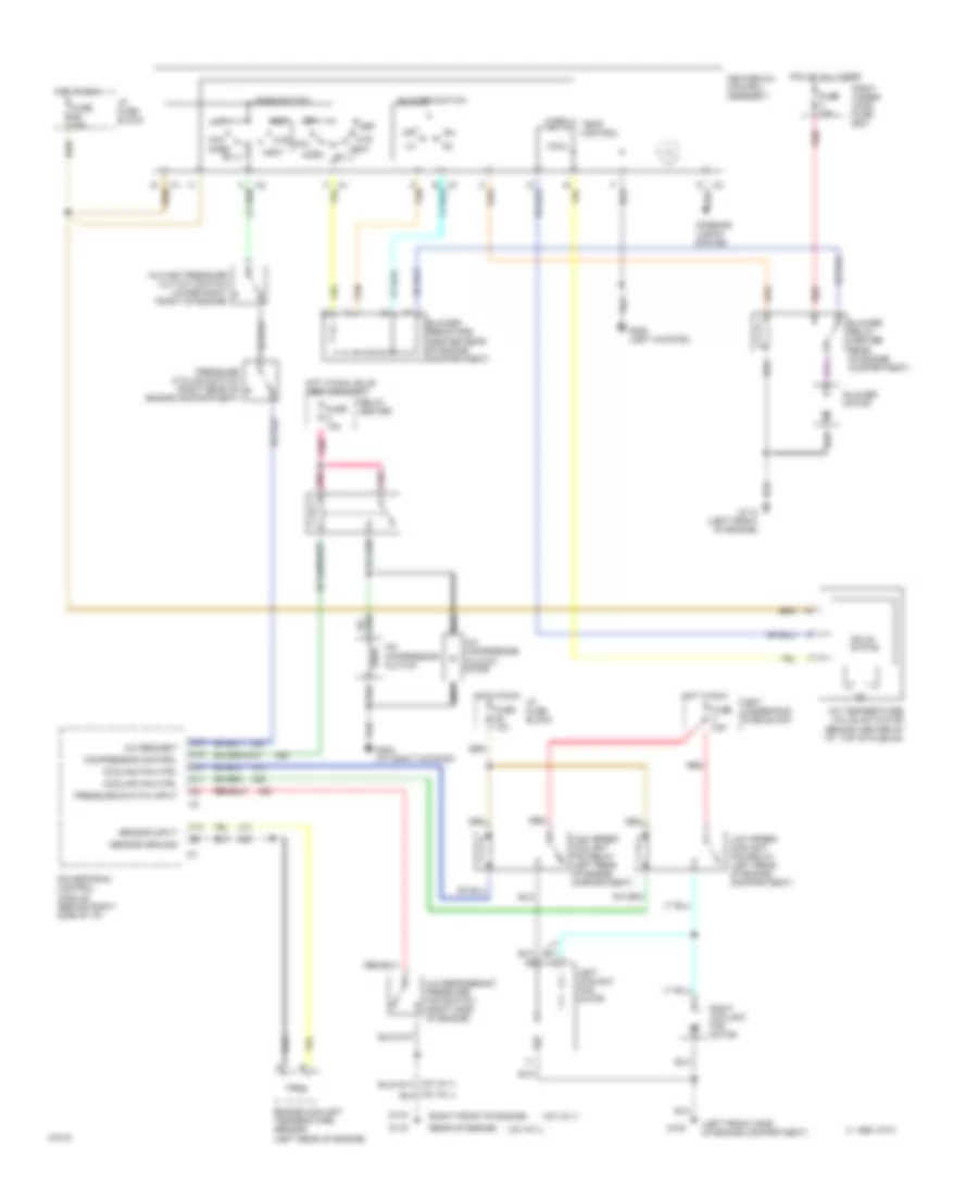
A/C Wiring Diagram, Auto A/C (2 of 2) for Pontiac Bonneville SE 1995
List of elements for A/C Wiring Diagram, Auto A/C (2 of 2) for Pontiac Bonneville SE 1995:
- (left front side of engine compartment)
- (right front of engine)
- A/c high pressure cut-out switch (lower right front of engine)
- A/c refrigerant pressure fan switch (right side of engine)
- A/c request
- C 1995 vftc
- C16
- Compressor control
- Computer data lines system
- D10
- D11
- D12
- E & c data line
- Engine coolant temperature sensor (left rear of engine)
- F13
- Fan relay ctrl
- Fuse 40a
- Fuse 5c 10a
- G100
- G119
- G200 (left kick pad)
- Ground
- Heater and a/c control assembly
- High speed coolant fan relay (left rear of engine compartment)
- Hot in run
- I/p fuse block
- Ignition
- Illumination
- Interior lights system
- Left coolant fan motor
- Left underhood fuse block
- Low speed coolant fan relay (left rear of engine compartment)
- Powertrain control module (behind right side of i/p)
- Pressure cycling switch (right rear of engine compartmnent)
- Pressure sw input
- Red
- Right coolant fan motor
- Sensor ground
- Sensor input
- Vf dim input
A/C Wiring Diagram, Manual A/C for Pontiac Bonneville SE 1995
List of elements for A/C Wiring Diagram, Manual A/C for Pontiac Bonneville SE 1995:
- (left front side of engine compartment)
- (rear of engine)
- (right front of engine)
- (v6 vin 1)
- (v6 vin l)
- A tan
- A/c compressor clutch
- A/c compressor clutch diode
- A/c high pressure cut-out switch (lower right front of engine)
- A/c refrigerant pressure fan switch (right side of engine)
- A/c request
- A/c temperature valve actuator (behind center of i/p, top of plenum)
- Bi-lv
- Blower motor
- Blower relay (center rear of engine compartment)
- Blower resistors (center rear of engine compartment)
- Blower switch
- C 1995 vftc
- C16
- Compressor control
- Cool
- Cooling fan ctrl
- D10
- D11
- D12
- Def
- Engine coolant temperature sensor (left rear of engine)
- F13
- Fuse 15a
- Fuse 30a
- Fuse 40a
- Fuse 5c 10a
- Fuse 5d 25a
- G100
- G110 (left front of engine)
- G115
- G119
- G200 (left kickpad)
- G203 (at right kickpad)
- Heater-a/c control assembly
- High speed coolant fan relay (left rear of engine compartment)
- Hot at all times
- Hot in run
- Hot in run, bulb test or start
- Htr
- I/p fuse block
- Interior lights system
- Left coolant fan motor
- Left underhood fuse block
- Low speed coolant fan relay (left rear of engine compartment)
- Max
- Mode switch
- Nca
- Norm
- Off
- Pnk
- Powertrain control module (behind right side of i/p)
- Pressure cycling switch (right rear of engine compartment)
- Pressure switch input
- Red
- Relay center
- Right coolant fan motor
- Right under- hood fuse box
- Sensor ground
- Sensor input
- Solid state
- Tan
- Temp control
- Vent
- Warm

 Čeština
 Dansk
Dansk Deutsch
 Ελληνικά
 English
 English
 Español
 Suomi
Suomi Français
 Français
 עברית
עברית Hrvatski
 Magyar
 Italiano
 日本語
日本語 한국어
한국어 Nederlands
 Polski
 Português
 Português
 Română
 Slovenčina
 Slovenščina
 Svenska
 Türkçe
 中文 (中国)