СИСТЕМА КОНДИЦИОНЕРА
Электросхема кондиционера для GMC Jimmy 1999

Электросхема кондиционера для GMC Jimmy 1999 - Список элементов:
- (at a/c accumulator) a/c compressor pressure cycling switch
- (body harness, below i/p fuse block) sp201
- (dash harness, between breakout to ground splice & breakout to right courtesy lamp)
- (dome harness between breakouts to inside air temperature sensor & left sunshade mirror lamp, 5 cm from breakout to sensor)
- (engine harness, between breakouts to rear heated oxygen sensors connector & body harness connector, 7 cm from breakout to heated oxygen sensor connector)
- (engine harness, on cathode side of a/c compressor clutch diode, in breakout to a/c compressor & cutoff switch) s104
- (right rear of cylinder head) g117
- 5 volt ref
- 5v ref
- A nca
- A/c
- A/c comp rly ctrl
- A/c compres- sor clutch
- A/c compres- sor clutch diode
- A/c compressor clutch relay
- A/c compressor high pressure switch (on rear of a/c compressor)
- A/c cycling sw sig
- A/c fuse 10a
- A/c request
- A/c request sig
- A10
- Air inlet
- Air temperature valve sensor & motor (on top right side of heater)
- B nca
- B10
- Battery
- Blower motor (on right rear of engine compartment)
- Body relay block (behind left side of dash, near i/p fuse block)
- C10
- C11
- C12
- C13
- C14
- C15
- C16
- C2 underhood fuse block (on top of left front fender)
- Class 2
- Class 2 data
- D10
- D11
- D12
- D13
- D14
- D15
- D16
- Data link connector (dlc) (partial) (under left side of dash)
- Defogger system
- Defrost
- Elec actuator drive
- Elec actuator fbck
- Electric sensor rtn
- Electronic climate control (ecc) module
- G104 (left rear of engine compartment)
- G117 (right rear of cylinder head)
- G201 (right side of dash)
- G202 (left side of dash)
- Gnd
- Ground
- Heater
- Heater/ defrost
- Hot at all times
- Hot in run
- Hot in run & start
- Hvac 1 fuse 21 10a
- Hvac fuse 30a
- Hvac solenoid (behind right side of dash, on hvac assembly)
- I/p fuse block (on left end of dash)
- Ign e fuse 10a
- Ignition
- Illumination
- Inside air temperature sensor (in roof over driver's door)
- Inside temp sens sig
- Interior lights system
- Lower disc temp sens
- Lower discharge air temperature sensor (on left side of floor air outlet)
- Mode 1 drv
- Mode 2 drv
- Mode 3 drv
- Mode 4 drv
- Mode 5 drv
- Nca
- Outside air temperature sensor (on right radiator support bracket)
- Outside temp sens sig
- Power mirrors system (automatic day-night mirrors)
- Pwm signal output
- Rdo batt fuse 19 15a
- Red
- Rr defog
- S106
- S118 (body harness, between breakouts to blower motor & blower motor relay)
- S240 (dash harness, 4 cm from breakout to bcm module connector & breakout to instrument cluster)
- S288
- S302
- Sensor gnd
- Solid state
- Sp200 (on body harness, center front of dash)
- Sp203 (dash harness, in front of ashtray)
- Sun load temp sens
- Sunload sensor (top center of dash)
- Tan
- Underhood fuse block (on top of left front fender)
- Upper disc temp sens
- Upper discharge air temperature sensor (on top front center of dash, behind radio in duct)
- Vehicle control module (vcm) (on right front of engine compartment)
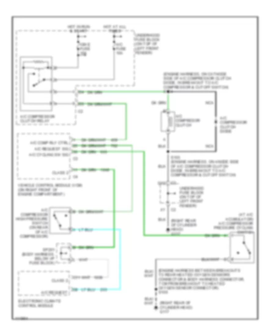
Электросхема компрессора, Авто A/C для GMC Jimmy 1999
Электросхема компрессора, Авто A/C для GMC Jimmy 1999 - Список элементов:
- (at a/c acumulator) a/c compressor pressure cycling switch
- (engine harness between breakouts to rear heated oxygen sensors connector & body harness connector, 7 cm from breakout to heated oxygen sensor connector) s106
- (engine harness, on cathode side of a/c compressor clutch diode, in breakout to a/c compressor & cutoff switch) s104
- (right rear of cylinder head) g117
- A/c comp rly ctrl
- A/c compresor clutch
- A/c compressor clutch diode
- A/c compressor clutch relay
- A/c compressor high pressure switch (on rear of a/c compressor)
- A/c cycling sw sig
- A/c fuse 10a
- A/c request
- A/c request sig
- C11
- Class 2
- D12
- Electronic climate control module
- Hot at all times
- Hot in run & start
- Ign e fuse 10a
- Nca
- S103 (engine harness, on anode side of a/c compressor clutch diode, in breakout to a/c compressor & cutoff switch)
- Sp201 (body harness, below i/p fuse block)
- Underhood fuse block (on top of left front fender)
- Vehicle control module (vcm) (on right front of engine compartment)
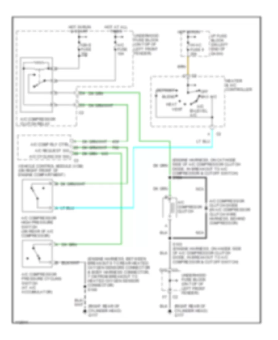
Электросхема компрессора, Ручное управление A/C для GMC Jimmy 1999
Электросхема компрессора, Ручное управление A/C для GMC Jimmy 1999 - Список элементов:
- (engine harness, between breakouts to rear heated oxygen sensors connector & body harness connector, 7 cm from breakout to heated oxygen sensor connector) s106
- (right rear of cylinder head) g117
- A/c
- A/c comp rly ctrl
- A/c compresor clutch
- A/c compressor clutch diode (in a/c compressor clutch wire harness, behind compressor)
- A/c compressor clutch relay
- A/c compressor high pressure switch (on rear of a/c compressor)
- A/c compressor pressure cycling switch (at a/c accumulator)
- A/c cycling sw sig
- A/c fuse 10a
- A/c request sig
- Bi-level a/c
- Blend
- D12
- Defrost
- Diode, in breakout to a/c compressor & cutoff switch) s104
- Heat
- Heater & a/c controller
- Hot at all times
- Hot in run
- Hot in run & start
- Hvac fuse 9 20a
- I/p fuse block (on left end of dash)
- Ign e fuse 10a
- Max a/c
- Nca
- Off
- S103 (engine harness, on anode side of a/c compressor clutch diode, in breakout to a/c compressor & cutoff switch)
- Underhood fuse block (on top of left front fender)
- Vehicle control module (vcm) (on right front of engine compartment)
- Vent
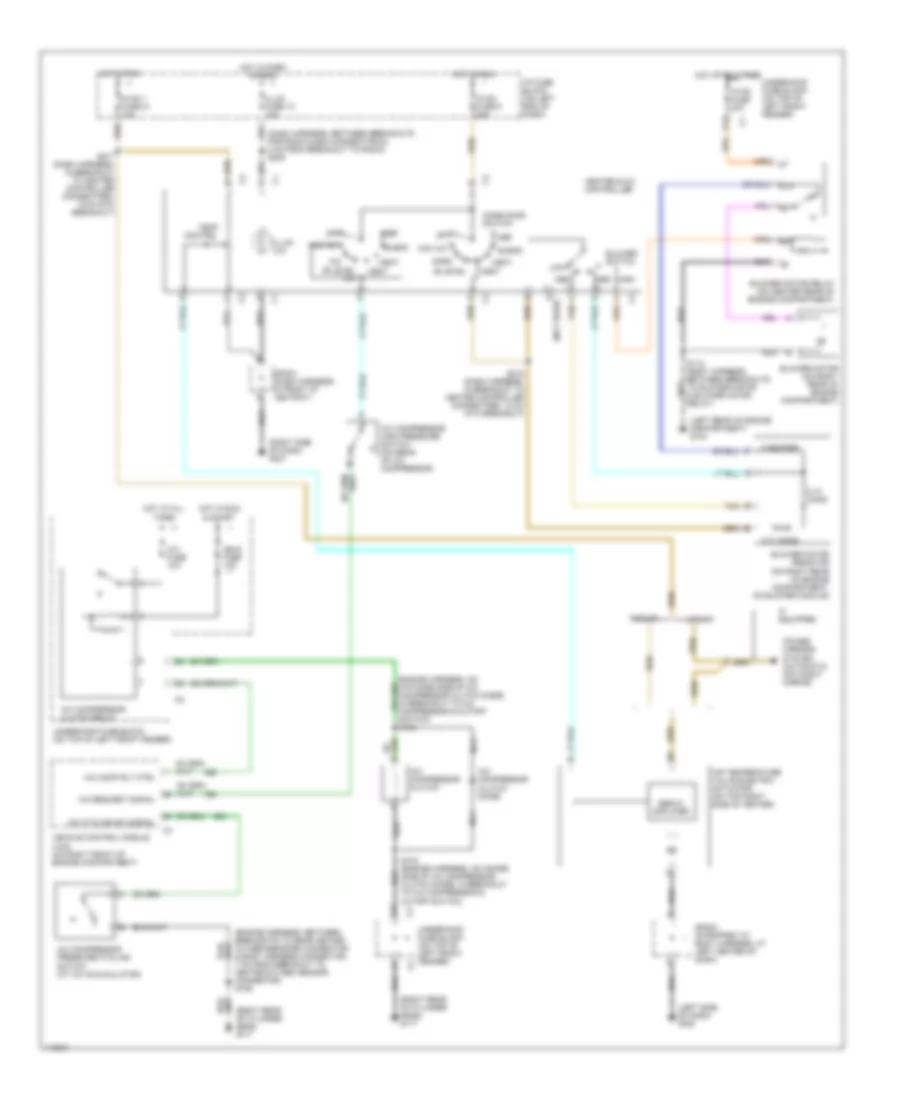
Электросхема кондиционера с ручный управлением для GMC Jimmy 1999
Электросхема кондиционера с ручный управлением для GMC Jimmy 1999 - Список элементов:
- (dash harness, between breakouts for radio & bcm connector c3, 8 cm from breakout to radio) s205
- (engine harness, between breakouts to rear heated oxygen sensors connector & body harness connector, 7 cm from breakout to heated oxygen sensor connector) s106
- (left rear of engine compartment) g104
- (left side of dash) g202
- (right rear of cylinder head) g117
- (right side of dash) g201
- 0.26 ohms
- 0.71 ohms
- 2.10 ohms
- 87a
- A/c
- A/c comp rly ctrl
- A/c compressor clutch
- A/c compressor clutch diode
- A/c compressor clutch relay
- A/c compressor high pressure switch (on rear of a/c compressor)
- A/c compressor pressure cycling switch (at a/c accumulator)
- A/c cycling sw signal
- A/c fuse 10a
- A/c request signal
- Air temperature valve electric actuator (on top right side of heater)
- Bi-level
- Bi-level a/c
- Blend
- Blower motor (on right rear of engine compartment)
- Blower motor relay (on center rear of engine compartment)
- Blower motor resistor (on right rear of engine compartment, on blower module)
- Blower switch
- D (not used)
- D12
- Def
- Heat
- Heater & a/c controller
- High
- Hot at all times
- Hot in park & head
- Hot in run
- Hot in run & start
- Hvac 1 fuse 21 10a
- Hvac fuse 30a
- Hvac fuse 9 20a
- I/p fuse block (on left end of dash)
- If equipped
- Ign e fuse 10a
- Illum (x4)
- Illum fuse 12 10a
- Low
- Max a/c
- Med
- Mode door switch
- Nca
- Norm
- Off
- Pickup
- Power mirrors system (automatic day/night mirror)
- S103 (engine harness, on anode side of a/c compressor clutch diode, in breakout to a/c compressor & cutoff switch)
- S118 (body harness, between breakouts to blower motor & blower motor relay)
- S215 (dash harness, in breakout to heater controller connectors, 10 cm into breakout)
- S217 (dash harness, in breakout to heater controller connectors, 6 cm into breakout)
- Servo amplifier
- Sp202 (strapped to body harness, at left center of dash)
- Sp203 (dash harness, in front of ashtray)
- Switch) s104
- Tan
- Temp control
- Underhood fuse block (on top of left front fender)
- Utility
- Vehicle control module (vcm) (on right front of engine compartment)
- Vent