ANTI-LOCK BRAKES
Anti-lock Brake Wiring Diagrams for Mazda 626 DX 1994
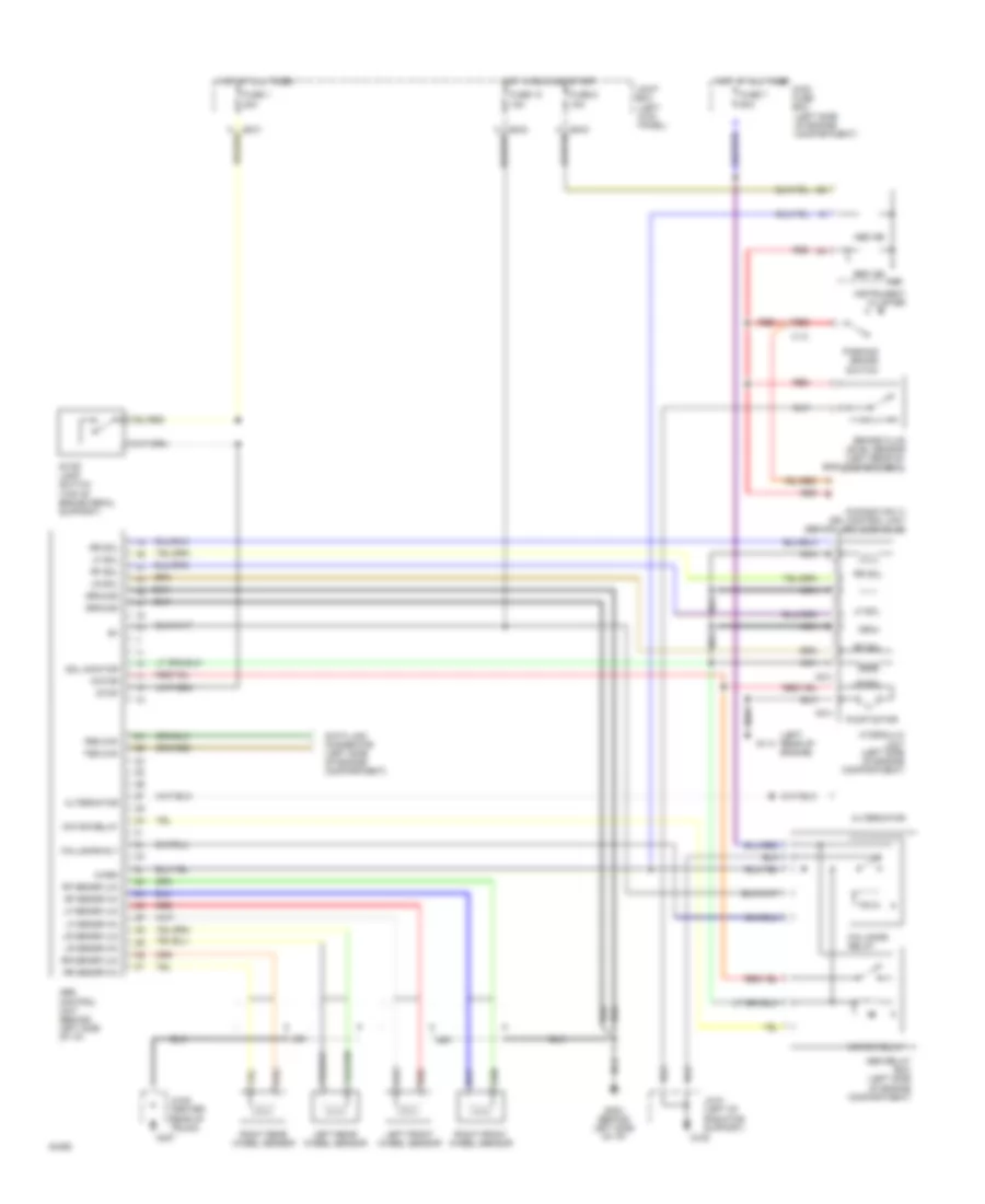
List of elements for Anti-lock Brake Wiring Diagrams for Mazda 626 DX 1994:
- (canada only) drl control unit (behind left side of i/p)
- (left kick panel)
- (left rear of engine)
- (left side of engine compartment)
- (top of brake pedal support)
- 2b
- Abs control unit (behind left side of i/p)
- Abs ind
- Abs relay box (left side of engine compartment)
- Alternator
- Brake fluid level sensor (left rear of eng compartment)
- Brk ind
- Data link connector (left side of engine compartment)
- Fail-safe relay
- Fail-safe rly
- Fbs chk
- Fuse 1 20a
- Fuse 10 15a
- Fuse 7 60a
- Fuse 8 15a
- G108
- G114
- G202 (behind left side of i/p)
- G407
- Ground
- Hot at all times
- Hot at all times main fuse box
- Hot in run and start
- Hydraulic unit (left side of engine compartment)
- Ind
- Instrument cluster
- Jc-01 (left of radiator support)
- Jc-05 (center rear of trunk)
- Joint box
- Left front wheel sensor
- Left rear wheel sensor
- Lf sensr (hi)
- Lf sensr (lo)
- Lf sol
- Lr sensr (hi)
- Lr sensr (lo)
- Lr sol
- Motor
- Motor relay
- Nca
- O-03
- O-04
- Parking brake switch
- Pump motor
- Red
- Rf sensr (hi)
- Rf sensr (lo)
- Rf sol
- Right front wheel sensor
- Right rear wheel sensor
- Rr sensr (hi)
- Rr sensr (lo)
- Rr sol
- Sol monitor
- Stop
- Stop lamp switch
- Tbs chk
- Warn
- X-13
 Čeština
 Dansk
Dansk Deutsch
 Ελληνικά
 English
 English
 Español
 Suomi
Suomi Français
 Français
 עברית
עברית Hrvatski
 Magyar
 Italiano
 日本語
日本語 한국어
한국어 Nederlands
 Polski
 Português
 Português
 Română
 Slovenčina
 Slovenščina
 Svenska
 Türkçe
 中文 (中国)
 Русский