ANTI-LOCK BRAKES
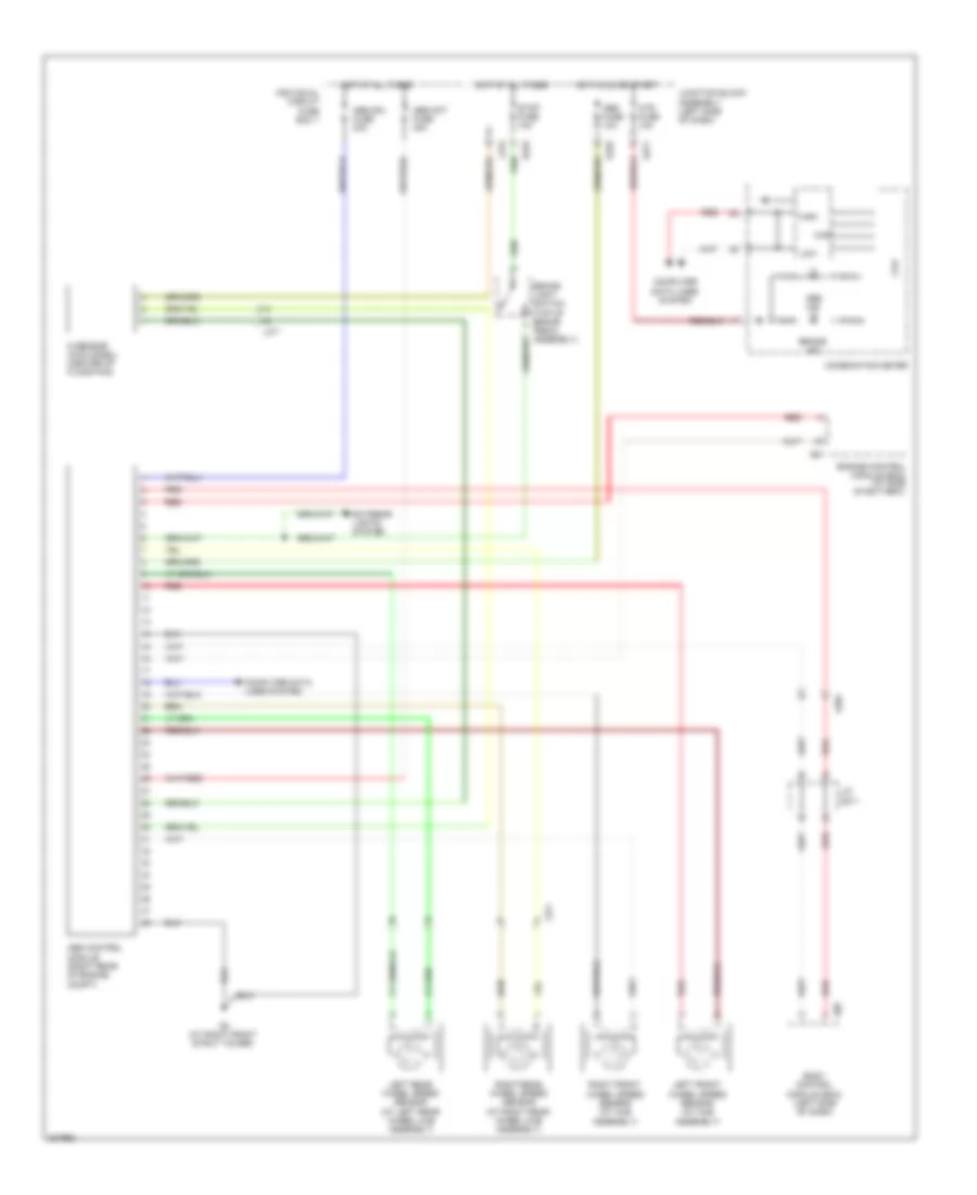
Anti-lock Brakes Wiring Diagram, with ESP for Suzuki SX4 LE 2010
 https://portal-diagnostov.com/license.html
Automotive Electricians Portal FZCO
Automotive Electricians Portal FZCO
https://portal-diagnostov.com/license.html
https://portal-diagnostov.com/license.html
Automotive Electricians Portal FZCO
Automotive Electricians Portal FZCO
List of elements for Anti-lock Brakes Wiring Diagram, with ESP for Suzuki SX4 LE 2010:
- (at right front strut tower) g8
- (in steering column assembly) steering angle sensor
- Abs fuse 10a
- Abs ind
- Abs mot fuse 40a
- Abs sol fuse 30a
- Brake ind
- Brake light switch (top of brake pedal assembly)
- Can
- Combination meter
- Computer data lines system
- Cpu
- Dome fuse 15a
- E01
- E323
- E325
- E381
- Engine control module (ecm) (at side of battery)
- Esp active ind
- Esp control module (right rear of engine compartment)
- Esp ind
- Esp off switch
- Exterior lights system
- G13 (behind left kick panel)
- G16 (under front passenger's seat)
- G17 (under driver's seat)
- G21 (hatch back: base of left "d" pillar) (sedan: at left rear wheel well)
- G271
- G272
- G341
- High
- Hot at all times
- Hot in on or start
- Ig 1 sig fuse 10a
- Individual circuit fuse box 1
- Instrument cluster system
- Interior lights system
- J/c 309
- J/c g308
- J/c g311
- J/c l348
- Junction block assembly (left side of dash)
- L315
- Left front wheel speed sensor (at hub assembly)
- Left rear wheel speed sensor (at left rear wheel hub assembly)
- Low
- Mtr fuse 10a
- Red
- Right front wheel speed sensor (at hub assembly)
- Right rear wheel speed sensor (at right rear wheel hub assembly)
- Stop fuse 15a
- Tcss off ind
- Yaw/g sensor (under center console, below parking brake handle)
Anti-lock Brakes Wiring Diagram, without ESP for Suzuki SX4 LE 2010
List of elements for Anti-lock Brakes Wiring Diagram, without ESP for Suzuki SX4 LE 2010:
- Abs control module (right rear of engine compt)
- Abs fuse 10a
- Abs ind
- Abs mot fuse 40a
- Abs sol fuse 30a
- Body control module (bcm) (left side of dash)
- Brake ind
- Brake light switch (top of brake pedal assembly)
- Can
- Combination meter
- Computer data lines system
- Computer data lines system
- Cpu
- E01
- E323
- E325
- E381
- Engine control module (ecm) (at side of battery)
- Exterior lights system
- G sensor (4wd model) (center of floor pan)
- G05
- G271
- G8 (at right front strut tower)
- High
- Hot at all times
- Hot in on or start
- Individual circuit fuse box 1
- J/c g311
- Junction block assembly (left side of dash)
- L315
- L371
- Left front wheel speed sensor (at hub assembly)
- Left rear wheel speed sensor (at left rear wheel hub assembly)
- Low
- Mtr fuse 10a
- Red
- Right front wheel speed sensor (at hub assembly)
- Right rear wheel speed sensor (at right rear wheel hub assembly)
- Stop fuse 10a

 Čeština
 Dansk
Dansk Deutsch
 Ελληνικά
 English
 English
 Español
 Suomi
Suomi Français
 Français
 עברית
עברית Hrvatski
 Magyar
 Italiano
 日本語
日本語 한국어
한국어 Nederlands
 Polski
 Português
 Português
 Română
 Slovenčina
 Slovenščina
 Svenska
 Türkçe
 中文 (中国)