COOLING FAN
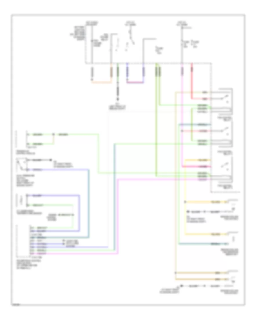
Cooling Fan Wiring Diagram, Except Hybrid for Mazda Tribute i Sport 2008
 https://portal-diagnostov.com/license.html
Automotive Electricians Portal FZCO
Automotive Electricians Portal FZCO
https://portal-diagnostov.com/license.html
https://portal-diagnostov.com/license.html
Automotive Electricians Portal FZCO
Automotive Electricians Portal FZCO
List of elements for Cooling Fan Wiring Diagram, Except Hybrid for Mazda Tribute i Sport 2008:
- (2.3l)
- (3.0l)
- 0140-175b
- 0140-175e
- 0140-275b
- 0140-275e
- 2.3l
- 3.0l
- Battery junction box (bjb) (on left side of engine compt)
- Computer data lines system
- Cooling fan relay
- Cooling fan resistor (2.3l)
- Cylinder head temperature sensor (2.3l) (on right front of cylinder head)
- Dual pressure switch (on lower right front of engine compt)
- Engine control system
- Engine coolant temperature (ect) sensor (3.0l) (at rear of engine)
- Engine cooling fan motor 1
- Engine cooling fan motor 2
- Fuse 40a
- G11 (left front of engine compt)
- G3 (at right front of engine compt)
- G4 (at right front of engine compt)
- High speed fan control relay
- Hot at all times
- Hot in run or start
- Low speed fan control relay
- Pcm power diode
- Pcm power relay
- Powertrain control module (pcm) (at upper center of firewall)
- Red
Cooling Fan Wiring Diagram, Hybrid for Mazda Tribute i Sport 2008
List of elements for Cooling Fan Wiring Diagram, Hybrid for Mazda Tribute i Sport 2008:
- 0140-175b
- 0140-175e
- 0517-101
- Battery junction box (bjb) (on left side of engine compt)
- Computer data lines system
- Cylinder-head temperature sensor
- Dual pressure switch (on lower right front of engine compt)
- Engine control system
- Engine cooling fan dropping resistor 1
- Engine cooling fan motor 1
- Engine cooling fan motor 2
- Fan control relay 1
- Fan control relay 2
- Fan control relay 3
- Fuse 10a
- Fuse 40a
- G11 (left front of engine compt)
- G3 (at right front of engine compt)
- G4 (at right front of engine compt)
- Hot at all times
- Hot in run or start
- Pcm power diode
- Pcm power relay
- Powertrain control module (pcm) (at upper center of firewall)
- Red
- Transaxle control module

 Čeština
 Dansk
Dansk Deutsch
 Ελληνικά
 English
 English
 Español
 Suomi
Suomi Français
 Français
 עברית
עברית Hrvatski
 Magyar
 Italiano
 日本語
日本語 한국어
한국어 Nederlands
 Polski
 Português
 Português
 Română
 Slovenčina
 Slovenščina
 Svenska
 Türkçe
 中文 (中国)