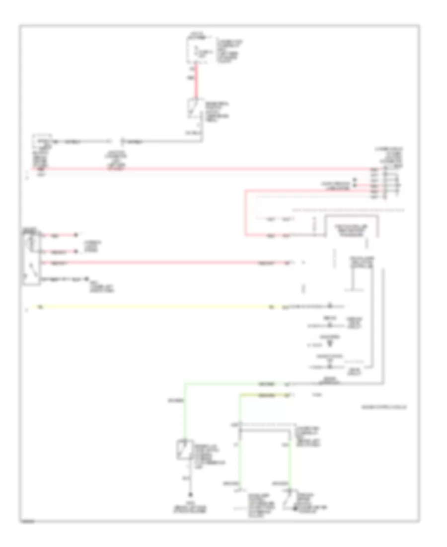
ANTI-LOCK BRAKES
Anti-lock Brakes Wiring Diagram (1 of 2) for Acura TL 2007
 https://portal-diagnostov.com/license.html
Automotive Electricians Portal FZCO
Automotive Electricians Portal FZCO
https://portal-diagnostov.com/license.html
https://portal-diagnostov.com/license.html
Automotive Electricians Portal FZCO
Automotive Electricians Portal FZCO
List of elements for Anti-lock Brakes Wiring Diagram (1 of 2) for Acura TL 2007:
- (under center console) yaw rate-lateral acceleration sensor
- C10
- C12
- Can-h
- Can-l
- Computer data lines system
- E12
- Fl +b
- Fl -gnd
- Fr +b
- Fr -gnd
- Fsr +b
- Fuse 17 30a
- Fuse 18 15a
- Fuse 18 40a
- Fuse 21 7.5a
- G203 (right side of engine compt)
- Glat
- Ground
- Hot at all times
- Hot in on or start
- Ignition in
- Junction connector c506 (left side of dash)
- K-line
- Left front wheel speed sensor (left side of engine compt)
- Left rear wheel speed sensor (under left rear of vehicle)
- Mr +b
- Pnk
- Red
- Right front wheel speed sensor (on right side of engine compt)
- Right rear wheel speed sensor (under right rear of vehicle)
- Rl +b
- Rl -gnd
- Rr +b
- Rr -gnd
- Sgnd
- Steering angle sensor (on side of steering column)
- Str-a
- Str-b
- Str-d
- Svcc
- Under-dash fuse/relay box (behind left end of dash)
- Under-hood fuse/relay box (left rear of engine compt)
- Vsa modulator unit (on right side of engine compt)
- X34
- Yaw
Anti-lock Brakes Wiring Diagram (2 of 2) for Acura TL 2007
List of elements for Anti-lock Brakes Wiring Diagram (2 of 2) for Acura TL 2007:
- (bksw) e8
- (under middle of dash) junction connector c512
- A13
- A14
- Abs ind
- B18
- Brake fluid level switch (integral to brake fluid reservoir cap)
- Brake pedal position switch (near brake pedal)
- Brake system ind
- Computer data lines system
- Cpu/fail safe circuit/can controller
- Drive circuit
- Ecm/pcm (behind center of dash)
- Fast controller area network transceiver
- Fuse 13 20a
- G302 (behind left side of front bumper)
- G501 (under left side of dash)
- Gauge control module
- Hot at all times
- Immobilizer control unit-receiver (on right side of steering column)
- Interior lights system
- Junction connector c507 (left side of dash)
- N30
- N34
- Parking brake switch (under center console)
- Red
- Sw input
- Under-dash fuse/relay box (behind left end of dash)
- Under-hood fuse/relay box (left rear of engine compt)
- Vsa activation ind
- Vsa off switch
- Vsa system ind
- Warning drive circuit

 Čeština
 Dansk
Dansk Deutsch
 Ελληνικά
 English
 English
 Español
 Suomi
Suomi Français
 Français
 עברית
עברית Hrvatski
 Magyar
 Italiano
 日本語
日本語 한국어
한국어 Nederlands
 Polski
 Português
 Português
 Română
 Slovenčina
 Slovenščina
 Svenska
 Türkçe
 中文 (中国)