СИСТЕМА КОНДИЦИОНЕРА
Электросхема кондиционера (1 из 2) для Mercedes-Benz C280 1999

Электросхема кондиционера (1 из 2) для Mercedes-Benz C280 1999 - Список элементов:
- (behind instrument cluster) g202
- (not used)
- 12v
- 15x
- 20b
- 29b
- 30a
- 38a
- A/c compressor
- A/c pushbutton control module
- Aspirator blower
- Auxiliary fan
- Blwr ctrl
- Cmpr cltch
- Coolant circulation pump (in lower right front of engine compartment, on frame rail)
- Data
- Data link connector (dtc readout) (partial) (in module box, on right rear corner of engine compartment)
- Diag
- Driver-side fuse & relay module box
- Duovalve
- Ed b
- Ed m
- Fr b
- Fuse & relay box (on left rear of engine compartment)
- Fuse 10a
- Fuse 15a
- Fuse 30a
- Fuse 38 60a (0r 30a)
- Hot at all times
- Hot in run or start
- In-car temperature sensor
- In-car temperature sensor (in dome light assembly)
- Instrument cluster
- Left-side water valve
- Nca
- Pnk
- Pump
- Refrigerant pressure sensor (on receiver-drier, behind left headlight)
- Refrigerant temperature sensor (on receiver-drier, behind left headlight)
- Right-side water valve
- Suction fan
- Sun
- Switchover valve block
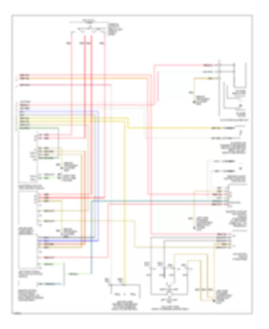
Электросхема кондиционера (2 из 2) для Mercedes-Benz C280 1999
Электросхема кондиционера (2 из 2) для Mercedes-Benz C280 1999 - Список элементов:
- (behind instrument cluster) g202
- (left side of engine compartment, near strut tower) g102
- 15x
- A/c system blower unit
- Air control module (if equipped)
- Auxiliary fans (front of engine compartment)
- B10
- B11
- B12
- Blower motor
- Blower regulator
- Can h
- Can l
- Computer data lines system
- Driver side fuse & relay module box
- Electric cooling fan control module (if equipped) (in left front wheelwell, on frame rail)
- Electronic ignition lock control module
- Engine control module (me-sfi) (in module box, on right rear of engine compartment)
- Engine/climate control electric cooling fan
- Evaporator temperature sensor (above accelerator pedal, on left side of heater box)
- Heater core temperature sensor (in console behind radio, on heater box)
- Hot at all times
- Left auxiliary fan
- Left front signal pickup & activation module
- Nca
- Pwm ctrl
- Red
- Right auxiliary fan
- Terminal block x4 (below left side of dash)