СИСТЕМА КОНДИЦИОНЕРА
Электросхема кондиционера для Mercedes-Benz ML320 1998
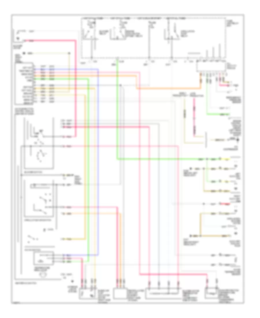
Электросхема кондиционера для Mercedes-Benz ML320 1998 - Список элементов:
- A/c compressor
- A/c on
- A/c on in
- A/c on switch
- A/c pushbutton control module (center of dash)
- A12
- All activity module
- Auxiliary coolant pump
- B12
- Blend air flap actuator motor (right side of dash)
- Blower motor
- Blower motor preresistor group (lower right side of dash)
- Blower relay
- Blower switch
- C/c
- C/g
- Circulating air switch
- Circulation pump relay
- Early production
- Engine control module (me-sfi) (left rear of engine compt)
- Engine cooling fan stage 1 relay
- Fuse 15a
- Fuse 30a
- Fuse and relay box
- G106 (behind left headlight)
- G107 (behind right headlight)
- G203 (right kick panel)
- Ground
- Heater a/c switch
- Hot at all times
- Hot in run or start
- Icing protection temperature sensor (in upper passenger's footwell)
- Ignition
- In-car temperature sensor
- Interior lights system
- Late production
- Left auxiliary fan
- M/a
- Ml/b
- Module box blower motor
- Mot cool
- Mot hot
- Nca
- Off
- Pnk
- Recirculated air flap element (right side of dash)
- Red
- Refrigerant pressure sensor
- Right auxiliary fan
- Sens gnd
- Sens in
- Tan
- Temp reg in
- Temperature regulator
- Vref
 Русский