СИСТЕМА КРУИЗКОНТРОЛЯ
Электросхема системы круизконтроля для Mercedes-Benz CLS500 2006
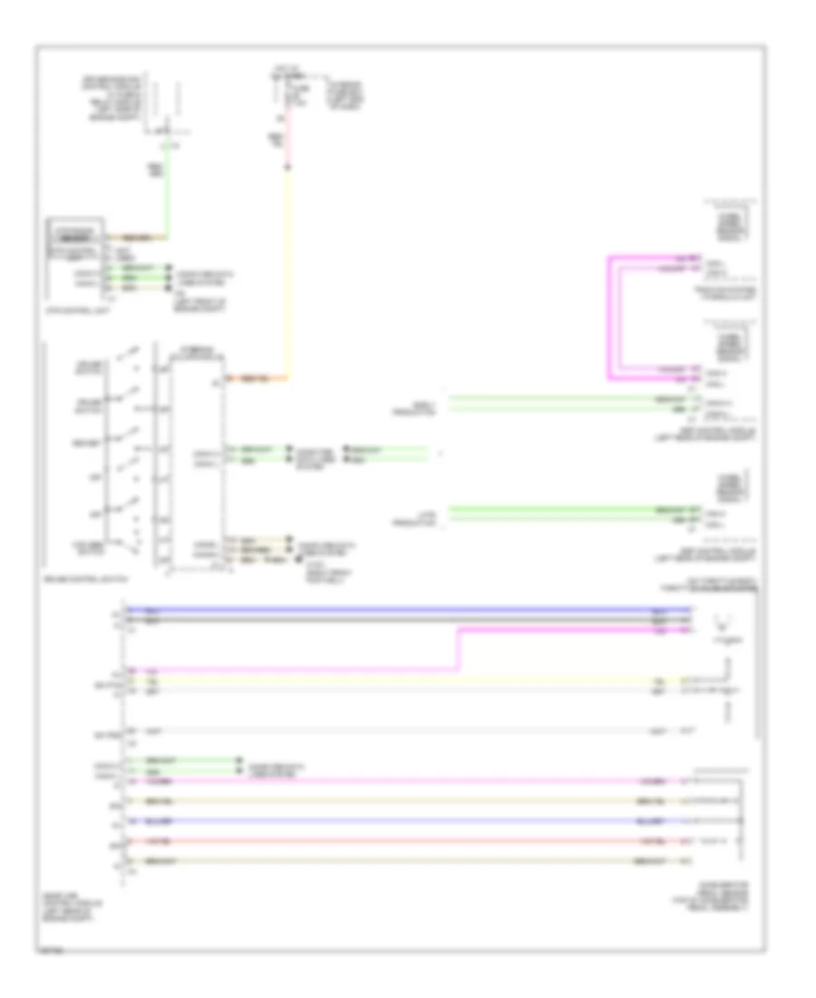
Электросхема системы круизконтроля для Mercedes-Benz CLS500 2006 - Список элементов:
- (not used)
- (on throttle body) throttle valve actuator
- Accelerator pedal sensor (top of accelerator pedal assembly)
- Can h
- Can l
- Can-b h
- Can-b l
- Can-c h
- Can-c l
- Computer data lines system
- Cruise control switch
- Cruise switch
- Dec/set
- Driver-side sam control module w/ fuse & relay module (left side of engine compt)
- Dtr control unit
- Dtr radar sensor
- Ea ip1s
- Ea ip2s
- Early production
- Esp control module (left rear of engine compt)
- Fuse 7.5a
- Hot at all times
- I12
- Interior fuse box (left end of dash)
- Late production
- Me-sfi (me) control module (left rear of engine compt)
- Off
- Sig
- Steering column module
- Traction system hydraulic unit
- Vcs (sbs) switch
- W15/1 (right front footwell)
- W9 (left front of engine compt)
- Wheel speed sensor signal
 Русский